下記の実施形態1~4等において説明する各図は、模式的な図であり、図中の各構成要素の大きさの比が、必ずしも実際の寸法比を反映しているとは限らない。
Each drawing described in Embodiments 1 to 4, etc. below is a schematic drawing, and the size ratio of each component in the drawing does not necessarily reflect the actual size ratio.
(実施形態1)
以下では、実施形態1に係る照明システム10について図1~6に基づいて説明する。
(Embodiment 1)
The illumination system 10 according to the first embodiment will be described below with reference to FIGS. 1 to 6. FIG.
(1)概要
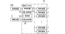
実施形態1に係る照明システム10は、図1に示すように、複数の照明装置1と、制御装置3と、を備える。制御装置3は、複数の照明装置1を制御する。複数の照明装置1は、図2に示すように、施設200内に配置される。施設200としては、ビル、特に、オフィスビルを想定している。以下では、説明の便宜上、施設200内において複数の照明装置1が面する空間を対象空間201という。対象空間201は、施設200内の人P10によって利用される空間である。対象空間201の例としては、会議室、ワーキングスペース、コワーキングスペース、レクリエーションルームが挙げられる。施設200は、オフィスビルに限らず、事務所、工場、病院、ホテル、スタジアム、アミューズメント施設、空港、戸建て住宅、集合住宅等であってもよい。
(1) Overview A lighting system 10 according to Embodiment 1 includes a plurality of lighting devices 1 and a control device 3, as shown in FIG. The control device 3 controls the plurality of lighting devices 1 . A plurality of lighting devices 1 are arranged in a facility 200 as shown in FIG. The facility 200 is assumed to be a building, particularly an office building. Hereinafter, for convenience of explanation, the space facing the plurality of lighting devices 1 in the facility 200 is referred to as a target space 201 . The target space 201 is a space used by the person P10 within the facility 200 . Examples of target space 201 include conference rooms, working spaces, co-working spaces, and recreation rooms. The facilities 200 are not limited to office buildings, but may be offices, factories, hospitals, hotels, stadiums, amusement facilities, airports, detached houses, collective housing, and the like.
制御装置3は、対象事象に関する情報を取得したときに、対象事象に基づくサインを提示するように複数の照明装置1のうち少なくとも1つの照明装置1の照明光を白色とは異なる色のカラー照明光に制御する。これにより、カラー照明光と当該カラー照明光を出力している照明装置1とを情報の媒体として活用することが可能となる。図5では、複数(例えば、12)の照明装置1のうち白色とは異なる色(例えば、赤色)のカラー照明光を照らしている4つの照明装置1の光出射面にドットハッチングを施し、白色の照明光を照らしている照明装置1の光出射面にはドットハッチングを施していない。
When the information on the target event is acquired, the control device 3 changes the illumination light of at least one of the plurality of lighting devices 1 to a color different from white so as to present a sign based on the target event. Control to light. This makes it possible to utilize the color illumination light and the illumination device 1 that outputs the color illumination light as information media. In FIG. 5, the light exit surfaces of four illumination devices 1, among a plurality of (eg, 12) illumination devices 1, which are illuminated with colored illumination light of a color (eg, red) different from white are hatched with dots. Dot hatching is not applied to the light exit surface of the illumination device 1 which illuminates the illumination light of .
(2)詳細
以下、実施形態1に係る照明システム10について、図1~6に基づいて更に詳細に説明する。
(2) Details The lighting system 10 according to the first embodiment will be described in further detail below with reference to FIGS. 1 to 6. FIG.
照明システム10は、上述のように、複数の照明装置1と、制御装置3と、を備える。
The lighting system 10 includes a plurality of lighting devices 1 and a control device 3 as described above.
複数の照明装置1は、例えば、図2に示すように、施設200において対象空間201に面する天井202に配置されている。対象空間201は、天井202下の空間である。施設200内の対象空間201には、人P10が利用可能な什器として、机220、椅子230等が配置されている。複数の照明装置1は、対象空間201から見て正方形状であるが、これに限らず、例えば、長方形状又は円形状であってもよい。複数の照明装置1は、対象空間201から見て2次元アレイ状に配置されている。複数の照明装置1は、天井埋め込み型の照明器具でもよいし、天井直付け型の照明器具でもよいし、システム天井に含まれるグリッド状の支持部材に支持されるパネル状の照明器具でもよいし、天井吊り下げ型の照明器具でもよい。
For example, as shown in FIG. 2, a plurality of lighting devices 1 are arranged on a ceiling 202 facing a target space 201 in a facility 200 . A target space 201 is a space under the ceiling 202 . In the target space 201 in the facility 200, a desk 220, a chair 230, and the like are arranged as fixtures usable by the person P10. The plurality of lighting devices 1 has a square shape when viewed from the target space 201, but is not limited to this, and may have, for example, a rectangular shape or a circular shape. A plurality of lighting devices 1 are arranged in a two-dimensional array when viewed from the target space 201 . The plurality of lighting devices 1 may be ceiling-embedded lighting fixtures, ceiling-mounted lighting fixtures, or panel-shaped lighting fixtures supported by grid-shaped support members included in the system ceiling. , Ceiling-hanging luminaires may also be used.
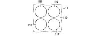
複数の照明装置1の各々は、光源11(図3参照)を備える。光源11は、例えば、図3に示すように、青色LED(Light Emitting Diode)11Bと、緑色LED11Gと、赤色LED11Rと、白色LED11Wと、を有する。
Each of the plurality of lighting devices 1 includes a light source 11 (see FIG. 3). For example, as shown in FIG. 3, the light source 11 has a blue LED (Light Emitting Diode) 11B, a green LED 11G, a red LED 11R, and a white LED 11W.
青色LED11Bは、青色光を放射する。緑色LED11Gは、緑色光を放射する。赤色LED11Rは、赤色光を放射する。白色LED11Wは、白色光を放射する。白色LED11Wから放射される白色光の相関色温度は、例えば、2700K以上6000K以下である。白色LED11Wは、例えば、青色LEDチップと、青色LEDチップから放射された青色光の一部を波長変換して青色光とは異なる波長の光を放射する波長変換要素を含む波長変換部と、を有する。波長変換要素は、蛍光体粒子である。波長変換部は、例えば、透光性材料部と、蛍光体粒子と、を含む。この場合、波長変換部は、透光性材料部と蛍光体粒子との混合体により形成されている。波長変換部では、透光性材料部内に多数の蛍光体粒子が存在している。透光性材料部の材料(透光性材料)は、可視光に対する透過率が高い材料が好ましい。透光性材料は、例えば、シリコーン系樹脂である。蛍光体粒子としては、例えば、黄色の光を放射する黄色蛍光体粒子を採用することができる。黄色蛍光体粒子から放射される光(蛍光)は、例えば、530nm~580nmの波長域に主発光ピーク波長がある発光スペクトルを有するのが好ましい。黄色蛍光体粒子は、例えば、Ceで付活されたY3Al5O12であるが、これに限らない。また、波長変換部は、波長変換要素として、黄色蛍光体粒子のみを含む場合に限らず、例えば、黄色蛍光体粒子と、黄緑色蛍光体粒子と、緑色蛍光体粒子と、赤色蛍光体粒子と、を含んでいてもよい。つまり、波長変換部は、複数種の蛍光体粒子を含んでいてもよい。黄緑色蛍光体粒子は、黄緑色の光を放射する。緑色蛍光体粒子は、緑色の光を放射する。赤色蛍光体粒子は、赤色の光を放射する。
Blue LED 11B emits blue light. The green LED 11G emits green light. The red LED 11R emits red light. The white LED 11W emits white light. The correlated color temperature of the white light emitted from the white LED 11W is, for example, 2700K or more and 6000K or less. The white LED 11W includes, for example, a blue LED chip and a wavelength conversion section including a wavelength conversion element that converts the wavelength of part of the blue light emitted from the blue LED chip and emits light with a wavelength different from that of the blue light. have. The wavelength converting elements are phosphor particles. The wavelength conversion section includes, for example, a translucent material section and phosphor particles. In this case, the wavelength converting portion is formed of a mixture of the translucent material portion and the phosphor particles. In the wavelength conversion section, a large number of phosphor particles are present in the translucent material section. The material of the translucent material portion (translucent material) is preferably a material having high visible light transmittance. The translucent material is, for example, silicone-based resin. As the phosphor particles, for example, yellow phosphor particles that emit yellow light can be used. The light (fluorescence) emitted from the yellow phosphor particles preferably has an emission spectrum with a main emission peak wavelength in the wavelength range of 530 nm to 580 nm, for example. The yellow phosphor particles are, for example, Y 3 Al 5 O 12 activated with Ce, but are not limited thereto. Further, the wavelength conversion part is not limited to the case where only yellow phosphor particles are included as wavelength conversion elements. For example, yellow phosphor particles, yellow-green phosphor particles, green phosphor particles, and red phosphor particles , may be included. In other words, the wavelength conversion section may contain a plurality of types of phosphor particles. Yellow-green phosphor particles emit yellow-green light. Green phosphor particles emit green light. Red phosphor particles emit red light.
また、光源11は、図3に示すように、実装基板110を有している。実装基板110は、例えば、プリント配線板である。青色LED11B、緑色LED11G、赤色LED11R及び白色LED11Wは、実装基板110に実装されている。光源11は、1つの実装基板110上に、青色LED11Bと、緑色LED11Gと、赤色LED11Rと、白色LED11Wとのセットを複数有している。
Also, the light source 11 has a mounting board 110 as shown in FIG. The mounting board 110 is, for example, a printed wiring board. The blue LED 11B, the green LED 11G, the red LED 11R and the white LED 11W are mounted on the mounting board 110. FIG. The light source 11 has a plurality of sets of a blue LED 11B, a green LED 11G, a red LED 11R, and a white LED 11W on one mounting board 110 .
複数の照明装置1の各々は、複数の青色LED11Bを駆動する第1駆動回路と、複数の緑色LED11Gを駆動する第2駆動回路と、複数の赤色LED11Rを駆動する第3駆動回路と、複数の白色LED11Wを駆動する第4駆動回路と、第1~第4駆動回路を制御する制御回路と、を備える。複数の照明装置1の各々では、制御回路が第1~第4駆動回路を制御することにより、照明光として、白色の光、青色の光、緑色の光、赤色の光のいずれか、又は、これらの2つ以上を混色して得られる色の光を出力可能である。要するに、複数の照明装置1の各々は、XYZ表色系のxy色度図において、青色LED11Bから放射される青色の光の色度点と、緑色LED11Gから放射される緑色の光の色度点と、赤色LED11Rから放射される赤色の光の色度点と、を頂点とする三角形の範囲内の任意の色度点に相当する色の光を、カラー照明光又は白色光として出力することが可能である。白色光は、XYZ表色系のxy色度図における黒体軌跡上の色度点に相当する色度の光であるのが好ましい。
Each of the plurality of lighting devices 1 includes a first drive circuit that drives the plurality of blue LEDs 11B, a second drive circuit that drives the plurality of green LEDs 11G, a third drive circuit that drives the plurality of red LEDs 11R, and a plurality of A fourth drive circuit for driving the white LED 11W and a control circuit for controlling the first to fourth drive circuits are provided. In each of the plurality of lighting devices 1, the control circuit controls the first to fourth drive circuits to select any one of white light, blue light, green light, and red light as illumination light, or It is possible to output light of a color obtained by mixing two or more of these colors. In short, each of the plurality of lighting devices 1 has a chromaticity point of blue light emitted from the blue LED 11B and a chromaticity point of green light emitted from the green LED 11G in the xy chromaticity diagram of the XYZ color system. and the chromaticity point of the red light emitted from the red LED 11R, and the light of a color corresponding to an arbitrary chromaticity point within the range of the triangle having the apexes thereof can be output as colored illumination light or white light. It is possible. The white light is preferably light of chromaticity corresponding to a chromaticity point on the black body locus in the xy chromaticity diagram of the XYZ color system.
制御装置3(図1参照)は、例えば、施設200(図2参照)の施設情報を記憶している管理装置330(図1参照)と通信ネットワークを介して接続可能である。管理装置330は、例えば、サーバである。通信ネットワークは、インターネットを含み得る。通信ネットワークは、単一の通信プロトコルに準拠したネットワークだけではなく、異なる通信プロトコルに準拠した複数のネットワークで構成されていてもよい。通信プロトコルは、周知の様々な有線及び無線通信規格から選択され得る。通信ネットワークは、例えば、リピータハブ、スイッチングハブ、ブリッジ、ゲートウェイ、ルータ等のデータ通信機器を含み得る。
For example, the control device 3 (see FIG. 1) can be connected via a communication network to the management device 330 (see FIG. 1) that stores facility information on the facility 200 (see FIG. 2). The management device 330 is, for example, a server. A communication network may include the Internet. The communication network may consist of not only a network conforming to a single communication protocol, but also a plurality of networks conforming to different communication protocols. Communication protocols may be selected from a variety of well-known wired and wireless communication standards. A communication network may include, for example, data communication equipment such as repeater hubs, switching hubs, bridges, gateways, routers, and the like.
施設情報は、例えば、施設200の構造を表す3次元データの一部又は全体である。3次元データは、コンピュータを用いて構築される仮想空間において施設200を表現するデータである。この種の3次元データは、例えば、BIM(Building Information Modeling)データである。以下では、3次元データを、「BIMデータ」という。
The facility information is, for example, part or all of three-dimensional data representing the structure of the facility 200. The three-dimensional data is data representing the facility 200 in a virtual space constructed using a computer. This type of three-dimensional data is, for example, BIM (Building Information Modeling) data. Below, three-dimensional data is called "BIM data."
BIMデータには、施設200の形状及び寸法を表すデータだけではなく、施設200を構成する部材に関するデータ、施設200に配置された設備機器に関するデータのように、施設200に関連する多種類のデータが統合されている。また、BIMデータには、施設200の基準位置の緯度・経度の情報、及び施設200の向きに関する情報が含まれている。つまり、BIMデータは、施設200を建てるためのデータだけではなく、施設200に関連する様々なデータの総体を表している。BIMデータは、例えば3次元CAD(Computer Aided Design)システムを用いて表現された情報であって、施設200の形状及び寸法を表すデータを用いて作成される。BIMデータを用いることで、例えばディスプレイに施設200の全体又は部分を表す図形を表示することが可能である。BIMデータは、施設200に応じて階層化されている。BIMデータは、例えば施設200の全体を正面図若しくは斜視図で表す情報、施設200の複数のフロアそれぞれを平面図若しくは斜視図で表す情報、又は一つのフロアを平面図若しくは斜視図で表す情報を含んでいる。例えば、BIMデータは、施設200である1つの建物全体の斜視図を表すデータ、建物内の1つのフロアの平面図を表すデータ、又は部屋を内側から見た斜視図を表すデータ等を含む。施設情報(BIMデータ)及び位置情報の表示は、いずれも例えばJava(登録商標)等のプログラム言語で記述されたプログラムを実行可能なソフトウェアを用いれば可能である。例えば、WebGL(Web Graphics Library)に対応したウェブブラウザであれば、施設200の3次元データを表示部に表示することが可能である。
BIM data includes not only data representing the shape and dimensions of the facility 200, but also various types of data related to the facility 200, such as data related to the members that make up the facility 200 and data related to equipment installed in the facility 200. are integrated. The BIM data also includes information on the latitude and longitude of the reference position of the facility 200 and information on the orientation of the facility 200 . In other words, the BIM data represents not only the data for building the facility 200 but also various data relating to the facility 200 . BIM data is information expressed using, for example, a three-dimensional CAD (Computer Aided Design) system, and is created using data representing the shape and dimensions of the facility 200 . By using BIM data, for example, it is possible to display a graphic representing the whole or part of the facility 200 on the display. BIM data is hierarchized according to the facility 200 . BIM data includes, for example, information representing the entire facility 200 in a front view or a perspective view, information representing each of a plurality of floors of the facility 200 in a plan view or a perspective view, or information representing one floor in a plan view or a perspective view. contains. For example, BIM data includes data representing a perspective view of an entire building that is the facility 200, data representing a plan view of one floor in the building, or data representing a perspective view of a room viewed from the inside. Both facility information (BIM data) and location information can be displayed using software capable of executing a program written in a programming language such as Java (registered trademark). For example, a web browser compatible with WebGL (Web Graphics Library) can display three-dimensional data of the facility 200 on the display unit.
制御装置3は、図1に示すように、管理装置330からBIMデータを取得する第1取得部31を有する。また、制御装置3は、施設200(図2参照)に関する火災発生情報を取得する第2取得部32を有する。第2取得部32は、例えば、施設200に配置されている煙感知器5(図1参照)又は自動火災報知システムから火災発生信号(発報信号)を取得する。自動火災報知システムは、例えば火災の発生を検知したときに、火災の発生を、防火対象物の在館者に報知することが可能な防災システムである。ここにおいて、防火対象物は、施設200である。煙感知器5は、例えば、自動火災報知システムの構成要素に含まれる場合もある。
The control device 3 has a first acquisition unit 31 that acquires BIM data from the management device 330, as shown in FIG. The control device 3 also has a second acquisition unit 32 that acquires fire outbreak information regarding the facility 200 (see FIG. 2). The second acquisition unit 32 acquires a fire occurrence signal (an alarm signal) from, for example, the smoke sensor 5 (see FIG. 1) installed in the facility 200 or an automatic fire alarm system. An automatic fire alarm system is a disaster prevention system capable of notifying people in a building of a fire prevention target of the outbreak of a fire, for example, when the outbreak of a fire is detected. Here, the fire prevention object is the facility 200 . A smoke detector 5 may be included, for example, as a component of an automatic fire alarm system.
また、制御装置3は、複数の照明装置1を制御する制御部33を有する。制御装置3と複数の照明装置1とは例えば信号線Lsを介して接続されており、制御装置3から複数の照明装置1に制御信号を伝送可能となっている。複数の照明装置1には、それぞれ個別の識別情報(固有アドレス)が設定されている。複数の照明装置1は、それぞれ固有アドレスを記憶している記憶部を有している。制御装置3では、制御部33は、動作モードとして、例えば、複数の照明装置1のうち2以上の照明装置1を一括して同じ制御内容で制御する第1モード(一括制御モード)と、1又は2以上の照明装置1をあらかじめ個々に設定した制御内容で制御する第2モード(パターン制御モード)と、複数の照明装置1を個別に制御する第3モード(個別制御モード)と、を有している。制御部33は、複数の照明装置1それぞれの固有アドレスを記憶しているメモリを含んでいる。また、制御部33は、第1モードのときに利用する一括制御用アドレスと、第2モードのときに利用するグループ制御アドレスと、を上述のメモリに記憶している。この場合、複数の照明装置1の記憶部は、固有アドレスに加えて、グループ制御用アドレス、一括制御用アドレスを記憶している。
The control device 3 also has a control unit 33 that controls the plurality of lighting devices 1 . The control device 3 and the plurality of lighting devices 1 are connected via, for example, signal lines Ls, and control signals can be transmitted from the control device 3 to the plurality of lighting devices 1 . Individual identification information (unique address) is set for each of the plurality of lighting devices 1 . A plurality of lighting devices 1 each have a storage unit that stores a unique address. In the control device 3, the control unit 33 has, as operation modes, for example, a first mode (collective control mode) in which two or more lighting devices 1 out of the plurality of lighting devices 1 are collectively controlled with the same control content; Alternatively, it has a second mode (pattern control mode) in which two or more lighting devices 1 are individually controlled in advance, and a third mode (individual control mode) in which a plurality of lighting devices 1 are individually controlled. is doing. The control unit 33 includes a memory that stores unique addresses for each of the lighting devices 1 . In addition, the control unit 33 stores a collective control address used in the first mode and a group control address used in the second mode in the memory described above. In this case, the storage units of the plurality of lighting devices 1 store group control addresses and batch control addresses in addition to unique addresses.
制御装置3は、第1取得部31において取得したBIMデータに基づいて、施設200内の複数の照明装置1の位置情報(施設200内の照明装置1の位置座標)を特定して、施設200内の複数の照明装置1の位置情報と複数の照明装置1の固有アドレスとを一対一に対応付けて上述のメモリに記憶している。制御部33から各照明装置1への制御信号は、制御対象の照明装置1の固有アドレス、一括制御用アドレス又はグループ制御用アドレスに対応するアドレスデータと、制御対象の照明装置1の制御内容(照明光の色、点灯、消灯、点滅、照度等)を示す制御データと、を含む。照明光の色は、白色又は白色とは異なる色(例えば、赤色、緑色、青色等)である。制御内容は、照明光の色を示す制御内容を含む制御データを含む代わりに、照明光の色度を示す制御内容を含む制御データを含んでいてもよい。
Based on the BIM data acquired by the first acquisition unit 31, the control device 3 identifies the positional information of the plurality of lighting devices 1 in the facility 200 (the positional coordinates of the lighting devices 1 in the facility 200). The positional information of the plurality of lighting devices 1 and the unique addresses of the plurality of lighting devices 1 are associated one-to-one and stored in the above memory. The control signal from the control unit 33 to each lighting device 1 includes address data corresponding to the unique address of the lighting device 1 to be controlled, the collective control address, or the group control address, and the control content of the lighting device 1 to be controlled ( and control data indicating the color of illumination light, lighting, lighting, blinking, illuminance, etc.). The color of the illumination light is white or a color different from white (for example, red, green, blue, etc.). The control content may include control data including control content indicating the chromaticity of the illumination light instead of including control data including the control content indicating the color of the illumination light.
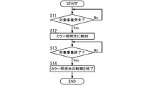
制御部33は、第2取得部32において対象事象(ここでは、火災)に関する情報(ここでは、火災発生情報)を取得したときに、対象事象(火災)に基づくサインを提示するように複数(図5の例では、12)の照明装置1のうち少なくとも1つ(図5の例では、4つ)の照明装置1の照明光を白色とは異なる色のカラー照明光に制御する。より詳細には、制御部33は、図4に示すように、対象事象に関する情報を取得すると(ステップS11:Yes)、対象事象に基づくサインを提示するように少なくとも1つの照明装置1の照明光を白色とは異なる色(例えば、赤色)のカラー照明光に制御する(ステップS12)。その後、対象事象に関する情報が終了すると(ステップS13:Yes)、カラー照明光の制御を終了する(ステップS14)。「カラー照明光の制御を終了する」とは、例えば、照明装置1の照明光を白色に制御すること、又は、照明装置1を消灯させること、を意味する。制御部33は、複数の照明装置1のうち少なくとも1つの照明装置1の照明光を白色とは異なる色のカラー照明光に制御する場合、例えば、上述の第2モードで動作する。対象事象が火災の場合、煙によって視界が悪くなっている可能性があるので、施設200内において発報した煙感知器5が対象空間201に配置されている煙感知器であれば、カラー照明光の色は、例えば、視認性を高める観点から、長波長の色が好ましく、例えば、赤色が好ましい。なお、制御装置3は、BIMデータに基づいて煙感知器5の位置情報も記憶している。
When the second acquiring unit 32 acquires information (here, fire occurrence information) about the target event (here, fire), the control unit 33 presents a plurality of (fire) signs based on the target event (fire). In the example of FIG. 5, the illumination light of at least one (four in the example of FIG. 5) of the illumination devices 1 of 12) is controlled to color illumination light of a color different from white. More specifically, as shown in FIG. 4, when the control unit 33 acquires information about the target event (step S11: Yes), the illumination light of at least one lighting device 1 is turned on to present a sign based on the target event. is controlled to color illumination light of a color different from white (for example, red) (step S12). After that, when the information about the target event is finished (step S13: Yes), the control of the color illumination light is finished (step S14). “Ending the control of the color illumination light” means, for example, controlling the illumination light of the illumination device 1 to be white or turning off the illumination device 1 . When controlling the illumination light of at least one illumination device 1 out of the plurality of illumination devices 1 to color illumination light of a color different from white, the controller 33 operates, for example, in the above-described second mode. If the target event is a fire, there is a possibility that visibility is poor due to smoke. The color of the light is preferably a color with a long wavelength, for example, red, from the viewpoint of improving visibility. The control device 3 also stores position information of the smoke sensor 5 based on the BIM data.
対象事象は、施設200内の人P10を誘導する必要のある事象(ここでは、火災)である。制御装置3は、対象事象に関する情報(火災発生情報)を取得したときに、施設200内の人P10へのサインとして、施設200内において対象空間201に滞在している人P10を誘導する方向D10(例えば、対象空間201から非常口又は出口に向かう方向)を示すサインを提示するように少なくとも1つの照明装置1を制御する。ここで、制御装置3は、例えば、図5に示すように、人P10を誘導する方向D10を示すサインを、カラー照明光のグラデーションで示してもよい。カラー照明光のグラデーションは、例えば、カラー照明光のグラデーションを示すための例えば4つの照明装置1のうち始点となる照明装置1のカラー照明光の色の濃淡度が最も低く、終点となる照明装置1のカラー照明光の色の濃淡度が最も高くなり、始点の照明装置1から離れて終点の照明装置1に近づくにつれてカラー照明光の色の濃淡度が徐々に高くなるようなグラデーションである。図5では、4つの照明装置1の光出射面におけるカラー照明光の濃淡度の高低をドットハッチングの種類によって区別している。
The target event is an event (here, fire) that needs to guide the person P10 in the facility 200. When the information about the target event (fire occurrence information) is acquired, the control device 3 guides the person P10 staying in the target space 201 in the facility 200 in a direction D10 as a sign for the person P10 in the facility 200. At least one lighting device 1 is controlled to present a sign indicating a direction (for example, a direction from the target space 201 to an emergency exit or exit). Here, for example, as shown in FIG. 5, the control device 3 may indicate a sign indicating a direction D10 to guide the person P10 by gradation of color illumination light. For the gradation of color illumination light, for example, among the four illumination devices 1 for indicating the gradation of color illumination light, the color intensity of the color illumination light of the illumination device 1 that is the starting point is the lowest, and the gradation of the color illumination light is the lighting device that is the end point. The gradation is such that the color gradation of the color illumination light of 1 is the highest, and the color gradation of the color illumination light gradually increases as the distance from the illumination device 1 at the starting point approaches the illumination device 1 at the end point. In FIG. 5, the degree of gradation of color illumination light on the light exit surfaces of the four illumination devices 1 is distinguished by the type of dot hatching.
制御装置3は、施設200内において対象空間201に滞在している人P10を誘導する方向を示すサインとして、例えば、図6に示すように、カラー照明光を出力する照明装置1を、人P10を誘導する方向に沿って逐次変化させてもよい。図6では、複数の照明装置1のうちカラー照明光を出力している照明装置1の光出射面にのみにドットハッチングを施してある。
For example, as shown in FIG. may be sequentially changed along the guiding direction. In FIG. 6, among the plurality of lighting devices 1, only the light exit surface of the lighting device 1 that outputs color illumination light is hatched with dots.
制御装置3(図1参照)は、コンピュータシステムを含んでいる。コンピュータシステムは、ハードウェアとしてのプロセッサ及びメモリを主構成とする。コンピュータシステムのメモリに記録されたプログラムをプロセッサが実行することによって、制御装置3としての機能が実現される。プログラムは、コンピュータシステムのメモリに予め記録されてもよく、電気通信回線を通じて提供されてもよく、コンピュータシステムで読み取り可能なメモリカード、光学ディスク、ハードディスクドライブ等の非一時的記録媒体に記録されて提供されてもよい。コンピュータシステムのプロセッサは、半導体集積回路(IC)又は大規模集積回路(LSI)を含む1ないし複数の電子回路で構成される。ここでいうIC又はLSI等の集積回路は、集積の度合いによって呼び方が異なっており、システムLSI、VLSI(Very Large Scale Integration)、又はULSI(Ultra Large Scale Integration)と呼ばれる集積回路を含む。さらに、LSIの製造後にプログラムされる、FPGA(Field-Programmable Gate Array)、又はLSI内部の接合関係の再構成若しくはLSI内部の回路区画の再構成が可能な論理デバイスについても、プロセッサとして採用することができる。複数の電子回路は、1つのチップに集約されていてもよいし、複数のチップに分散して設けられていてもよい。複数のチップは、1つの装置に集約されていてもよいし、複数の装置に分散して設けられていてもよい。ここでいうコンピュータシステムは、1以上のプロセッサ及び1以上のメモリを有するマイクロコントローラを含む。したがって、マイクロコントローラについても、半導体集積回路又は大規模集積回路を含む1ないし複数の電子回路で構成される。
The control device 3 (see FIG. 1) includes a computer system. A computer system is mainly composed of a processor and a memory as hardware. The function of the control device 3 is realized by the processor executing a program recorded in the memory of the computer system. The program may be recorded in advance in the memory of the computer system, may be provided through an electric communication line, or may be recorded in a non-temporary recording medium such as a computer system-readable memory card, optical disk, or hard disk drive. may be provided. A processor in a computer system consists of one or more electronic circuits, including semiconductor integrated circuits (ICs) or large scale integrated circuits (LSIs). Integrated circuits such as ICs or LSIs are called differently depending on the degree of integration, and include integrated circuits called system LSI, VLSI (Very Large Scale Integration), or ULSI (Ultra Large Scale Integration). In addition, FPGAs (Field-Programmable Gate Arrays), which are programmed after the LSI is manufactured, or logic devices capable of reconfiguring the connection relationships inside the LSI or reconfiguring the circuit partitions inside the LSI, shall also be adopted as processors. can be done. A plurality of electronic circuits may be integrated into one chip, or may be distributed over a plurality of chips. A plurality of chips may be integrated in one device, or may be distributed in a plurality of devices. A computer system, as used herein, includes a microcontroller having one or more processors and one or more memories. Accordingly, the microcontroller also consists of one or more electronic circuits including semiconductor integrated circuits or large scale integrated circuits.
(3)制御方法及びプログラム
実施形態1に係る制御方法は、施設200内に配置される複数の照明装置1を制御する制御方法である。実施形態1に係る制御方法では、対象事象に関する情報を取得したときに、対象事象に基づくサインを提示するように複数の照明装置1のうち少なくとも1つの照明装置1の照明光を白色とは異なる色のカラー照明光に制御する。
(3) Control Method and Program The control method according to the first embodiment is a control method for controlling a plurality of lighting devices 1 arranged within the facility 200 . In the control method according to the first embodiment, when the information on the target event is acquired, the illumination light of at least one of the plurality of lighting devices 1 is changed from white to present a sign based on the target event. Control to color color illumination light.
実施形態1に係るプログラムは、コンピュータシステム(制御装置3)に、上述の制御方法を実行させるためのプログラムである。
The program according to the first embodiment is a program for causing the computer system (control device 3) to execute the control method described above.
(4)まとめ
実施形態1に係る照明システム10は、複数の照明装置1と、制御装置3と、を備える。複数の照明装置1は、施設200内に配置される。制御装置3は、複数の照明装置1を制御する。制御装置3は、対象事象に関する情報(火災発生情報)を取得したときに、対象事象に基づくサインを提示するように複数の照明装置1のうち少なくとも1つの照明装置1の照明光を白色とは異なる色のカラー照明光に制御する。これにより、実施形態1に係る照明システム10では、照明装置1を複数の用途に利用することが可能となる。例えば、照明システム10は、制御装置3が対象事象に関する情報を取得していない通常時には、複数の照明装置1を、施設200の対象空間201を照明する主照明の用途として利用でき、制御装置3が対象事象に関する情報を取得したときには、照明装置1を、対象事象に基づくサインを提示するサイネージ用照明の用途として利用することができる。
(4) Summary The lighting system 10 according to the first embodiment includes a plurality of lighting devices 1 and a control device 3 . A plurality of lighting devices 1 are arranged in a facility 200 . The control device 3 controls the plurality of lighting devices 1 . When the control device 3 acquires information on the target event (fire occurrence information), the control device 3 sets the illumination light of at least one of the plurality of lighting devices 1 to be white so as to present a sign based on the target event. Control to color illumination light of different colors. Accordingly, in the lighting system 10 according to the first embodiment, the lighting device 1 can be used for multiple purposes. For example, the lighting system 10 can use the plurality of lighting devices 1 as main lighting for illuminating the target space 201 of the facility 200 when the control device 3 does not acquire information about the target event, and the control device 3 acquires information about the target event, the lighting device 1 can be used as signage lighting for presenting a sign based on the target event.
また、実施形態1に係る照明システム10は、施設200内で火災が発生した場合に、対象空間201内に滞在している人P10を非常口等の避難経路へ誘導するサインを提示することが可能となる。
In addition, the lighting system 10 according to the first embodiment can present a sign that guides the person P10 staying in the target space 201 to an evacuation route such as an emergency exit when a fire breaks out in the facility 200. becomes.
(5)実施形態1に係る照明システムにおける照明装置の変形例
(5.1)変形例1
複数の照明装置1の各々の備える光源11は、例えば、図7に示すように、第1青色LED111と、第2青色LED112と、第1波長変換部121と、第2波長変換部122と、可視光LED13(以下、第1可視光LED13ともいう)と、可視光LED14(以下、第2可視光LED14ともいう)と、を有している。
(5) Modification of lighting device in lighting system according to Embodiment 1 (5.1) Modification 1
For example, as shown in FIG. 7, the light source 11 included in each of the plurality of lighting devices 1 includes a first blue LED 111, a second blue LED 112, a first wavelength conversion section 121, a second wavelength conversion section 122, It has a visible light LED 13 (hereinafter also referred to as a first visible light LED 13) and a visible light LED 14 (hereinafter also referred to as a second visible light LED 14).
第1青色LED111は、第1青色光を放射する。第2青色LED112は、第2青色光を放射する。第1波長変換部121は、第1青色光によって励起されて緑色光を放射する緑色蛍光体粒子を含む。第2波長変換部122は、第2青色光によって励起されて赤色光を放射する赤色蛍光体粒子を含む。第1可視光LED13は、第1青色光及び第2青色光及び白色とは異なる色の可視光(以下、第1可視光ともいう)を放射する。第2可視光LED14は、第1青色光及び第2青色光及び白色とは異なる色の可視光(以下、第2可視光ともいう)を放射する。第2青色光のピーク波長は、第1青色光のピーク波長と同じであってもよいし、異なっていてもよい。第1可視光は、例えば、赤色光である。第2可視光は、例えば、緑色光である。第1可視光と第2可視光とは互いに異なる色の光に限らず、同じ色の光であってもよい。また、光源11は、第1可視光LED13と第2可視光LED14との両方を含んでいる場合に限らず、少なくとも一方を含んでいればよい。
The first blue LED 111 emits first blue light. The second blue LED 112 emits second blue light. The first wavelength converter 121 includes green phosphor particles that are excited by the first blue light to emit green light. The second wavelength converter 122 includes red phosphor particles that are excited by the second blue light to emit red light. The first visible light LED 13 emits visible light of a color different from the first blue light, the second blue light, and white (hereinafter also referred to as the first visible light). The second visible light LED 14 emits visible light of a color different from the first blue light, the second blue light, and white (hereinafter also referred to as the second visible light). The peak wavelength of the second blue light may be the same as or different from the peak wavelength of the first blue light. The first visible light is, for example, red light. The second visible light is, for example, green light. The first visible light and the second visible light are not limited to light of different colors, and may be light of the same color. Moreover, the light source 11 is not limited to including both the first visible light LED 13 and the second visible light LED 14, and may include at least one of them.
第1青色LED111と、第2青色LED112と、第1波長変換部121と、第2波長変換部122と、第1可視光LED13と、第2可視光LED14とは、実装基板110に設けられている。また、光源11は、1つの実装基板110上に、第1青色LED111と、第2青色LED112と、第1波長変換部121と、第2波長変換部122と、第1可視光LED13と、第2可視光LED14とのセットを複数有している。
First blue LED 111 , second blue LED 112 , first wavelength conversion section 121 , second wavelength conversion section 122 , first visible light LED 13 , and second visible light LED 14 are provided on mounting board 110 . there is Further, the light source 11 includes a first blue LED 111, a second blue LED 112, a first wavelength conversion section 121, a second wavelength conversion section 122, a first visible light LED 13, and a second blue LED 112 on one mounting substrate 110. It has a plurality of sets with 2 visible light LEDs 14 .
複数の照明装置1の各々は、複数の第1青色LED111を駆動する駆動回路と、複数の第2青色LED112を駆動する駆動回路と、複数の第1可視光LEDを駆動する駆動回路と、複数の第2可視光LED14を駆動する駆動回路と、各駆動回路を制御する制御回路と、を備える。
Each of the plurality of lighting devices 1 includes a drive circuit that drives the plurality of first blue LEDs 111, a drive circuit that drives the plurality of second blue LEDs 112, a drive circuit that drives the plurality of first visible light LEDs, and a plurality of and a control circuit for controlling each drive circuit.
変形例1では、照明装置1を主照明用途で利用するときに、照明装置1の照明光の演色性を向上させることが可能となる。
In Modified Example 1, it is possible to improve the color rendering properties of the illumination light of the lighting device 1 when the lighting device 1 is used for main lighting purposes.
(5.2)変形例2
複数の照明装置1の各々の備える光源11は、例えば、図8に示すように、第1紫色LED131と、第2紫色LED132と、第3紫色LED133と、第1波長変換部141と、第2波長変換部142と、第3波長変換部143と、を有する。また、光源11は、可視光LED15を更に有する。
(5.2) Modification 2
For example, as shown in FIG. 8, the light source 11 included in each of the plurality of lighting devices 1 includes a first violet LED 131, a second violet LED 132, a third violet LED 133, a first wavelength converter 141, and a second It has a wavelength converter 142 and a third wavelength converter 143 . Moreover, the light source 11 further has a visible light LED 15 .
第1紫色LED131は、第1紫色光を放射する。第2紫色LED132は、第2紫色光を放射する。第3紫色LED133は、第3紫色光を放射する。第1波長変換部141は、第1紫色光によって励起されて青色光を放射する青色蛍光体粒子を含む。第2波長変換部142は、第2紫色光によって励起されて緑色光を放射する緑色蛍光体粒子を含む。第3波長変換部143は、第3紫色光によって励起されて赤色光を放射する赤色蛍光体粒子を含む。可視光LED15は、可視光(例えば、赤色光)を放射する。第1紫色光と、第2紫色光と、第3紫色光とは、互いにピーク波長が同じであってもよいし、互いに異なっていてもよい。可視光LED15から放射される可視光は、赤色光に限らず、例えば、緑色光であってもよい。また、光源11は、可視光LED15を有していない構成であってもよい。
The first violet LED 131 emits first violet light. The second violet LED 132 emits second violet light. The third violet LED 133 emits third violet light. The first wavelength converter 141 includes blue phosphor particles that are excited by the first violet light to emit blue light. The second wavelength converter 142 includes green phosphor particles that are excited by the second violet light to emit green light. The third wavelength converter 143 includes red phosphor particles that are excited by the third violet light to emit red light. Visible light LED 15 emits visible light (eg, red light). The peak wavelengths of the first violet light, the second violet light, and the third violet light may be the same or different. The visible light emitted from the visible light LED 15 is not limited to red light, and may be green light, for example. Further, the light source 11 may be configured without the visible light LED 15 .
第1紫色LED131と、第2紫色LED132と、第3紫色LED133と、第1波長変換部141と、第2波長変換部142と、第3波長変換部143と、可視光LED15とは、実装基板110に設けられている。また、光源11は、1つの実装基板110上に、第1紫色LED131と、第2紫色LED132と、第3紫色LED133と、第1波長変換部141と、第2波長変換部142と、第3波長変換部143と、可視光LED15とのセットを複数有している。
The first violet LED 131, the second violet LED 132, the third violet LED 133, the first wavelength conversion section 141, the second wavelength conversion section 142, the third wavelength conversion section 143, and the visible light LED 15 are mounted on a mounting substrate. 110. Further, the light source 11 includes a first violet LED 131, a second violet LED 132, a third violet LED 133, a first wavelength conversion section 141, a second wavelength conversion section 142, and a third A plurality of sets of the wavelength conversion unit 143 and the visible light LED 15 are provided.
複数の照明装置1の各々は、複数の第1紫色LED131を駆動する駆動回路と、複数の第2紫色LED132を駆動する駆動回路と、複数の第3紫色LED133を駆動する駆動回路と、複数の可視光LED15を駆動する駆動回路と、各駆動回路を制御する制御回路と、を備える。
Each of the plurality of lighting devices 1 includes a drive circuit that drives the plurality of first violet LEDs 131, a drive circuit that drives the plurality of second violet LEDs 132, a drive circuit that drives the plurality of third violet LEDs 133, and a plurality of A drive circuit for driving the visible light LED 15 and a control circuit for controlling each drive circuit are provided.
変形例2では、照明装置1を主照明用途で利用するときに、照明装置1の照明光の演色性を向上させることが可能となる。
In Modified Example 2, it is possible to improve the color rendering properties of the illumination light of the lighting device 1 when the lighting device 1 is used for main lighting purposes.
(実施形態2)
以下、実施形態2に係る照明システム10aについて、図9に基づいて説明する。実施形態2に係る照明システム10aに関し、実施形態1に係る照明システム10と同様の構成要素には同一の符号を付して説明を省略する。
(Embodiment 2)
The lighting system 10a according to the second embodiment will be described below with reference to FIG. Regarding the lighting system 10a according to the second embodiment, the same components as those of the lighting system 10 according to the first embodiment are denoted by the same reference numerals, and description thereof is omitted.
照明システム10aは、複数の照明装置1である複数の第1照明装置1とは別体であり施設200内に配置される複数の第2照明装置2を更に備える。
The lighting system 10 a further includes a plurality of second lighting devices 2 arranged in the facility 200 separately from the plurality of first lighting devices 1 that are the plurality of lighting devices 1 .
複数の第2照明装置2の照明光は、白色光である。ここにおいて、複数の第2照明装置2の照明光は、相関色温度が2700K以上6000K以下の白色光である。
The illumination light from the plurality of second lighting devices 2 is white light. Here, the illumination light from the plurality of second lighting devices 2 is white light with a correlated color temperature of 2700K or more and 6000K or less.
制御装置3は、複数の照明装置1及び複数の第2照明装置2を制御する。制御装置3は、複数の第2照明装置2の識別情報及び位置情報を記憶している。
The control device 3 controls the multiple lighting devices 1 and the multiple second lighting devices 2 . The control device 3 stores identification information and position information of the plurality of second lighting devices 2 .
照明システム10aでは、第2照明装置2は、一方向において第1照明装置1に隣り合うように配置されている。第1照明装置1の光出射面は、長方形状である。第2照明装置2の光出射面は、長方形状である。照明システム10aでは、第1照明装置1の光出射面の面積は、第2照明装置2の光出射面の面積よりも小さい。照明システム10aでは、第1照明装置1の照明エリアは、第2照明装置2の照明エリアよりも狭い。
In the lighting system 10a, the second lighting device 2 is arranged adjacent to the first lighting device 1 in one direction. The light exit surface of the first lighting device 1 is rectangular. The light exit surface of the second lighting device 2 is rectangular. In the illumination system 10 a , the area of the light exit surface of the first lighting device 1 is smaller than the area of the light exit surface of the second lighting device 2 . In the lighting system 10 a , the lighting area of the first lighting device 1 is narrower than the lighting area of the second lighting device 2 .
照明システム10aは、複数の第2照明装置2の照明光を主照明として利用することができる。
The illumination system 10a can use illumination light from the plurality of second illumination devices 2 as main illumination.
照明システム10aでは、制御装置3は、対象事象に関する情報を取得したときに、対象事象に基づくサインを提示するように複数の第1照明装置1のうち少なくとも1つの第1照明装置1の照明光を白色とは異なる色のカラー照明光に制御する。これにより、カラー照明光と当該カラー照明光を出力している第1照明装置1とを情報の媒体として活用することが可能となる。図9では、複数(例えば、9つ)の第1照明装置1のうち白色とは異なる色(例えば、赤色)のカラー照明光を照らしている4つの第1照明装置1の光出射面にドットハッチングを施し、白色の照明光を照らしている又は消灯している第1照明装置1の光出射面にはドットハッチングを施していない。
In the lighting system 10a, when the information on the target event is acquired, the control device 3 controls the illumination light of at least one first lighting device 1 out of the plurality of first lighting devices 1 so as to present a sign based on the target event. is controlled to color illumination light of a color different from white. This makes it possible to utilize the colored illumination light and the first lighting device 1 that outputs the colored illumination light as information media. In FIG. 9 , dots are shown on the light exit surfaces of four first lighting devices 1 that illuminate color illumination light (for example, red) different from white among the plurality (for example, nine) of first lighting devices 1 . Hatching is applied, and dot hatching is not applied to the light exit surface of the first lighting device 1 which is illuminated with white illumination light or is extinguished.
照明システム10aでは、複数の第2照明装置2は、照明光の相関色温度を調整可能であってもよい。
In the lighting system 10a, the plurality of second lighting devices 2 may be capable of adjusting the correlated color temperature of the illumination light.
(実施形態3)
以下、実施形態3に係る照明システム10bについて、図10及び11に基づいて説明する。実施形態3に係る照明システム10bは、実施形態1に係る照明システム10における制御装置3の代わりに制御装置3bを備えている点で実施形態1に係る照明システム10と相違する。実施形態3に係る照明システム10bに関し、実施形態1に係る照明システム10と同様の構成要素には同一の符号を付して説明を省略する。
(Embodiment 3)
The illumination system 10b according to the third embodiment will be described below with reference to FIGS. 10 and 11. FIG. The lighting system 10b according to the third embodiment differs from the lighting system 10 according to the first embodiment in that it includes a control device 3b instead of the control device 3 in the lighting system 10 according to the first embodiment. Regarding the lighting system 10b according to the third embodiment, the same components as those of the lighting system 10 according to the first embodiment are denoted by the same reference numerals, and description thereof is omitted.
照明システム10bでは、制御装置3bは、センサシステム340から、対象事象に関する情報を取得する。
In the lighting system 10b, the control device 3b acquires information about the target event from the sensor system 340.
センサシステム340は、施設200において複数の照明装置1が面している対象空間201を撮像するカメラを含む画像センサを備えている。カメラにおける撮像素子は、CMOS(Complementary MOS)イメージセンサである。撮像素子は、CMOSイメージセンサに限らず、例えば、CCD(Charge Coupled Device)イメージセンサ、赤外線イメージセンサ等でもよい。画像センサは、カメラで撮像して生成した画像に基づいて対象空間201内の人P10等の状態を検出することができる。画像センサは、画像を画像処理することで対象物(人P10等)の特徴量を求めて人P10の状態を検出することができる。センサシステム340は、1つの対象空間201に対して複数の画像センサを備えていてもよい。センサシステム340では、画像センサには、個別の識別情報(アドレス)が設定されている。
The sensor system 340 includes an image sensor including a camera that captures an image of the target space 201 facing the multiple lighting devices 1 in the facility 200 . The imaging element in the camera is a CMOS (Complementary MOS) image sensor. The imaging element is not limited to a CMOS image sensor, and may be, for example, a CCD (Charge Coupled Device) image sensor, an infrared image sensor, or the like. The image sensor can detect the state of the person P10 or the like in the target space 201 based on the image captured by the camera and generated. The image sensor can detect the state of the person P10 by obtaining the feature amount of the target object (person P10 or the like) by performing image processing on the image. Sensor system 340 may include multiple image sensors for one object space 201 . In the sensor system 340, individual identification information (address) is set for each image sensor.
制御装置3bは、センサシステム340から、対象事象に関する情報を取得する取得部31bと、取得部31bにおいて対象事象に関する情報を取得したときに、対象事象に基づくサインを提示するように複数の照明装置1のうち少なくとも1つの照明装置1の照明光を白色とは異なる色のカラー照明光に制御する制御部33bと、を有する。制御装置3bでは、照明装置1の位置情報、照明装置1の照明エリア、画像センサの位置情報、画像センサのカメラの撮像エリア等に基づいて、制御部33bの有するメモリに、1つの画像センサの識別情報を1つの照明装置1の識別情報に対応付けて記憶されていてもよいし、1つの画像センサの識別情報を2以上の照明装置1の識別情報に対応付けて記憶されていてもよい。
The control device 3b includes an acquisition unit 31b that acquires information on a target event from the sensor system 340, and a plurality of lighting devices that present a sign based on the target event when the acquisition unit 31b acquires information on the target event. and a control unit 33b for controlling the illumination light of at least one illumination device 1 out of the 1 to color illumination light of a color different from white. Based on the position information of the lighting device 1, the lighting area of the lighting device 1, the position information of the image sensor, the imaging area of the camera of the image sensor, and the like, the control device 3b stores the information of one image sensor in the memory of the control unit 33b. The identification information may be stored in association with the identification information of one lighting device 1, or the identification information of one image sensor may be stored in association with the identification information of two or more lighting devices 1. .
照明システム10bでは、対象事象は、施設200内の人P10の進行方向において注意を喚起する必要のある事象である。制御装置3bは、対象事象に関する情報を取得したときに、サインとして人P10の進行方向に注意を促すサインを提示するように少なくとも1つの照明装置1を制御する。これにより、照明システム10bでは、制御装置3bが、対象事象に関する情報として施設200内の人P10の進行方向において注意を喚起する必要のある事象に関する情報を取得したときに、照明装置1のカラー照明光によって、人P10の進行方向に注意を促すサインを提示することが可能となる。
In the lighting system 10b, the target event is an event that requires attention in the traveling direction of the person P10 in the facility 200. The control device 3b controls at least one lighting device 1 so as to present, as a sign, a sign calling attention to the traveling direction of the person P10 when the information on the target event is acquired. As a result, in the lighting system 10b, when the control device 3b acquires information about an event requiring attention in the traveling direction of the person P10 in the facility 200 as information about the target event, the color lighting of the lighting device 1 The light makes it possible to present a sign calling attention to the traveling direction of the person P10.
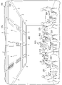
図11の例では、対象事象は、施設200内の人P10の進行方向において床面203が濡れている事象及び人P11が倒れている事象である。図11では、複数(例えば、12)の照明装置1のうち白色とは異なる色(例えば、赤色)のカラー照明光を照らしている2つの照明装置1の光出射面にドットハッチングを施し、白色の照明光を照らしている又は消灯している照明装置1の光出射面にはドットハッチングを施していない。照明システム10bでは、床面203が濡れている事象に注意を促すサインを提示することにより、人P10の転倒防止に役立てることが可能となる。また、照明システム10bでは、人P11が倒れている事象に注意を促すサインを提示することにより、倒れている人P11の存在を知らせることが可能となる。
In the example of FIG. 11, the target events are the event that the floor surface 203 is wet and the event that the person P11 is lying down in the direction in which the person P10 in the facility 200 moves. In FIG. 11, the light exit surfaces of two illumination devices 1, among a plurality of (eg, 12) illumination devices 1, which are illuminated with color illumination light of a color (eg, red) different from white are hatched with dots. Dot hatching is not applied to the light exit surface of the illumination device 1 which is illuminated with the illumination light of , or is extinguished. The illumination system 10b presents a sign calling attention to the fact that the floor surface 203 is wet, which can help prevent the person P10 from falling. Further, in the lighting system 10b, it is possible to notify the presence of the fallen person P11 by presenting a sign calling attention to the event that the person P11 has fallen down.
図12の例では、対象事象は、施設200内の人P10の進行方向において人P10の正面に椅子230が位置している事象である。図12では、複数(例えば、12)の照明装置1のうち白色とは異なる色(例えば、赤色)のカラー照明光を照らしている1つの照明装置1の光出射面にドットハッチングを施し、白色の照明光を照らしている又は消灯している照明装置1の光出射面にはドットハッチングを施していない。照明システム10bでは、人P10の進行方向において人P10の正面に椅子230が位置している事象に注意を促すことにより、人P10が椅子230に衝突することを抑制することが可能となる。
In the example of FIG. 12, the target event is an event in which the chair 230 is positioned in front of the person P10 in the traveling direction of the person P10 in the facility 200. In FIG. 12, the light exit surface of one of the plurality of (for example, 12) lighting devices 1 that illuminates color illumination light of a color (for example, red) different from white is hatched with dots. Dot hatching is not applied to the light exit surface of the illumination device 1 which is illuminated with the illumination light of , or is extinguished. In the lighting system 10b, it is possible to prevent the person P10 from colliding with the chair 230 by drawing attention to the fact that the chair 230 is positioned in front of the person P10 in the traveling direction of the person P10.
図13の例では、対象事象は、施設200内の通路の交差点に第1方向D1から人P10(P11)が接近する事象である。制御装置3bは、対象事象に関する情報を取得したときに、サインとして交差点に第1方向D1とは異なる第2方向D2から接近する人P10(P12)に第1方向D1から近づく人P10(P11)がいることを示すサインを提示するように複数の照明装置1のうち交差点を照明する照明装置1を制御する。図13では、複数(例えば、10)の照明装置1のうち白色とは異なる色(例えば、赤色)のカラー照明光を照らしている2つの照明装置1の光出射面にドットハッチングを施し、白色の照明光を照らしている又は消灯している照明装置1の光出射面にはドットハッチングを施していない。照明システム10bでは、交差点に第1方向D1から近づく人P11と交差点に第2方向D2から近づく人P12とが出合い頭に衝突することを抑制することが可能となる。照明システム10bでは、交差点に近づく人P10(P11)の接近速度に基づいて、カラー照明光の色を変えるように照明装置1を制御してもよい。例えば、接近速度が閾値よりも遅い場合には、カラー照明光の色を黄色として、接近速度が閾値以上の場合には、カラー照明光の色を赤色としてもよい。
In the example of FIG. 13, the target event is an event in which a person P10 (P11) approaches an intersection of passages in the facility 200 from the first direction D1. When the control device 3b acquires the information about the target event, the control device 3b uses the signal as a sign to indicate the person P10 (P12) approaching the intersection from the first direction D1 in the second direction D2, which is different from the first direction D1. A lighting device 1 for lighting an intersection among a plurality of lighting devices 1 is controlled so as to present a sign indicating that there is an intersection. In FIG. 13 , the light exit surfaces of two illumination devices 1 that illuminate color illumination light of a color (eg, red) different from white among a plurality of (eg, 10) illumination devices 1 are hatched with dots. Dot hatching is not applied to the light exit surface of the illumination device 1 which is illuminated with the illumination light of , or is extinguished. In the lighting system 10b, it is possible to prevent the head of the person P11 approaching the intersection from the first direction D1 and the person P12 approaching the intersection from the second direction D2 from colliding with each other. The lighting system 10b may control the lighting device 1 to change the color of the colored illumination light based on the approach speed of the person P10 (P11) approaching the intersection. For example, when the approach speed is slower than the threshold, the color of the colored illumination light may be yellow, and when the approach speed is equal to or higher than the threshold, the color of the colored illumination light may be red.
図13の例では、対象事象は、施設200内をロボットRo1が移動している事象であってもよい。この場合、制御装置3bは、対象事象に関する情報を取得したときに、サインとして施設200内のロボットRo1の移動予定経路を示すサインを提示するように少なくとも1つの照明装置1を制御する。これにより、照明システム10bでは、施設200内の人P10に、ロボットRo1に対する注意を促すことが可能となる。図13の例では、交差点に第2方向D2から近づく人P12に、交差点に第1方向D1からロボットRo1が移動していることを知らせることが可能となる。制御装置3bは、対象事象に関する情報を取得したときに、サインとして施設200内のロボットRo1の移動予定経路をロボットRo1の周囲の人P10に示すサインを提示するように少なくとも1つの照明装置1を制御するように構成されているが、これに限らない。例えば、制御装置3bは、対象事象に関する情報を取得したときに、サインとして施設200内のロボットRo1にロボットRo1の次の移動経路を知らせるサインを提示するように少なくとも1つの照明装置1を制御するように構成されていてもよい。
In the example of FIG. 13, the target event may be an event in which the robot Ro1 is moving within the facility 200. In this case, the control device 3b controls at least one lighting device 1 to present a sign indicating the planned movement route of the robot Ro1 in the facility 200 as a sign when the information on the target event is acquired. Thus, the lighting system 10b can call the person P10 in the facility 200 to pay attention to the robot Ro1. In the example of FIG. 13, it is possible to notify a person P12 approaching the intersection from the second direction D2 that the robot Ro1 is moving to the intersection from the first direction D1. When the information about the target event is acquired, the control device 3b controls at least one lighting device 1 so as to present a sign showing the planned movement route of the robot Ro1 in the facility 200 to the person P10 around the robot Ro1. Although it is configured to control, it is not limited to this. For example, the control device 3b controls at least one lighting device 1 to present, as a sign, to the robot Ro1 in the facility 200 a sign informing the next movement route of the robot Ro1 when the information on the target event is acquired. It may be configured as
図13の例では、対象事象は、施設200内の人P10(P11)が前方不注意で歩行している事象であってもよい。この場合、センサシステム340では、画像センサによって、例えばスマートフォン等を見ながら歩行している人P10を前方不注意で歩行している人P11として検知する。制御装置3bは、対象事象に関する情報を取得したときに、サインとして前方不注意の人P11又は前方不注意の人P11に接近している人P12に注意を促すサインを提示するように少なくとも1つの照明装置1を制御する。図13の例では、前方不注意の人P11及び前方不注意の人P11に接近している人P12に、カラー照明光によって注意を促すことが可能となる。人P10が前方不注意で歩行している事象は、人P10がスマートフォン等を見ながら歩行している事象に限らず、例えば、人P10がスマートフォンで通話しながら歩行している事象、又は、人P10が隣の人と横向きで話しながら歩行している事象であってもよい。
In the example of FIG. 13, the target event may be an event in which the person P10 (P11) in the facility 200 is walking carelessly ahead. In this case, the sensor system 340 detects a person P10 who is walking while looking at a smartphone, for example, as a person P11 who is carelessly walking forward. When the information about the target event is acquired, the control device 3b presents, as a sign, the careless person P11 or the person P12 approaching the careless person P11 with at least one sign. It controls the lighting device 1 . In the example of FIG. 13, it is possible to call attention to the person P11 who is inattentive ahead and the person P12 who is approaching the person P11 who is inattentive ahead by using colored illumination light. The event in which the person P10 is carelessly walking forward is not limited to the event in which the person P10 is walking while looking at a smartphone or the like. P10 may be an event in which the person is walking sideways while talking to the person next to him/her.
(実施形態4)
以下、実施形態4に係る照明システム10cについて、図14及び15に基づいて説明する。実施形態4に係る照明システム10cは、実施形態3に係る照明システム10bにおける制御装置3bの代わりに制御装置3cを備えている点で実施形態3に係る照明システム10bと相違する。実施形態4に係る照明システム10cに関し、実施形態3に係る照明システム10bと同様の構成要素には同一の符号を付して説明を省略する。
(Embodiment 4)
The illumination system 10c according to Embodiment 4 will be described below with reference to FIGS. 14 and 15. FIG. A lighting system 10c according to the fourth embodiment differs from the lighting system 10b according to the third embodiment in that a control device 3c is provided instead of the control device 3b in the lighting system 10b according to the third embodiment. With respect to the lighting system 10c according to the fourth embodiment, the same components as those of the lighting system 10b according to the third embodiment are denoted by the same reference numerals, and description thereof is omitted.
照明システム10cでは、制御装置3cは、施設200のBIMデータを取得する第1取得部31cと、対象事象に関する情報を取得する第2取得部32cと、複数の照明装置1を制御する制御部33cと、を有する。第1取得部31cは、実施形態1に係る照明システム10の制御装置3における第1取得部31と同様、管理装置330から施設200のBIMデータを取得する。第2取得部32cは、実施形態3に係る照明システム10bの制御装置3bにおける取得部31bと同様、センサシステム340から、対象事象に関する情報を取得する。制御部33cは、第2取得部32cにおいて対象事象に関する情報を取得したときに、対象事象に基づくサインを提示するように複数の照明装置1のうち少なくとも1つ(図15の例では、3つ)の照明装置1の照明光を白色とは異なる色のカラー照明光に制御する。
In the lighting system 10c, the control device 3c includes a first acquisition unit 31c that acquires BIM data of the facility 200, a second acquisition unit 32c that acquires information about the target event, and a control unit 33c that controls the plurality of lighting devices 1. and have The first acquisition unit 31c acquires the BIM data of the facility 200 from the management device 330, like the first acquisition unit 31 in the control device 3 of the lighting system 10 according to the first embodiment. The second acquisition unit 32c acquires information about the target event from the sensor system 340, like the acquisition unit 31b in the control device 3b of the lighting system 10b according to the third embodiment. When the second acquisition unit 32c acquires the information on the target event, the control unit 33c selects at least one of the plurality of lighting devices 1 (three in the example of FIG. 15) to present a sign based on the target event. ) is controlled to color illumination light of a color different from white.
照明システム10cでは、対象事象は、例えば図15に示すように、施設200内を人P10が移動している事象である。制御装置3cは、対象事象に関する情報を取得したときに、サインとして施設200内の人P10の動線を示すサインを提示するように少なくとも1つの照明装置1を制御する。これにより、照明システム10cは、人P10の動線を示すサインをカラー照明光で示すことができるので、施設200内を移動している人P10の動線を制御することが可能となる。
In the lighting system 10c, the target event is, for example, an event in which the person P10 is moving within the facility 200, as shown in FIG. The control device 3c controls at least one lighting device 1 to present a sign indicating the flow line of the person P10 in the facility 200 as a sign when the information about the target event is acquired. As a result, the lighting system 10c can indicate the sign indicating the flow line of the person P10 with colored illumination light, so that the flow line of the person P10 moving in the facility 200 can be controlled.
制御装置3cは、例えば、図15に示すように、人P10の動線を示すサインを、白色とは異なる色(例えば、緑色)のカラー照明光のグラデーションで示す。カラー照明光のグラデーションは、例えば、カラー照明光のグラデーションを示すための例えば3つの照明装置1のうち始点となる照明装置1のカラー照明光の色の濃淡度が最も高く、始点から離れた照明装置1ほどカラー照明光の色の濃淡度が低くなるようなグラデーションである。図15では、照明装置1の光出射面におけるカラー照明光の濃淡度の高低をドットハッチングの種類によって区別している。また、図15では、施設200の床面203において、カラー照明光によって照明されるエリアA1を、当該エリアA1に対応する照明装置1の光出射面と同じドットハッチングで示してある。図15の例では、床面203において照明装置1からのカラー照明光が照射されるエリア、つまり、カラー照明光によって照明されるエリアA1の大きさが、照明装置1の光出射面の大きさと同じであるが、実際には、照明装置1の光出射面の面積よりも大きい。
For example, as shown in FIG. 15, the control device 3c indicates the sign indicating the flow line of the person P10 with a gradation of color illumination light of a color different from white (for example, green). For the gradation of color illumination light, for example, among the three illumination devices 1 for indicating the gradation of color illumination light, the color intensity of the color illumination light of the illumination device 1 serving as the starting point is the highest, and the illumination farther from the starting point. The gradation is such that the color gradation of the color illumination light is lower in apparatus 1 . In FIG. 15, the degree of gradation of the color illumination light on the light exit surface of the illumination device 1 is distinguished by the type of dot hatching. Also, in FIG. 15, the area A1 illuminated by the color illumination light on the floor surface 203 of the facility 200 is indicated by the same dot hatching as the light exit surface of the illumination device 1 corresponding to the area A1. In the example of FIG. 15, the size of the area on the floor surface 203 irradiated with the color illumination light from the illumination device 1, that is, the size of the area A1 illuminated by the color illumination light is the size of the light exit surface of the illumination device 1. Identical, but actually larger than the area of the light exit surface of the illumination device 1 .
照明システム10cでは、対象事象は、例えば図16に示すように、施設200内を人P10が掃除する事象であってもよい。制御装置3cは、対象事象に関する情報を取得したときに、サインとして施設200内の掃除未完了のエリアを示すサインを提示するように、複数の照明装置1のうち掃除未完了のエリア(図16の例では、エリアA1~A6のうちエリアA3~A6)を照明する照明装置1を制御する。これにより、照明システム10cは、掃除をしている人P10に掃除未完了のエリアを分かりやすくすることが可能となる。
In the lighting system 10c, the target event may be, for example, an event in which a person P10 cleans the inside of the facility 200, as shown in FIG. When the information about the target event is acquired, the control device 3c presents a sign indicating an uncleaned area in the facility 200 as a sign to identify the uncleaned area (see FIG. 16) among the plurality of lighting devices 1. In the example of 2, the illumination device 1 that illuminates areas A3 to A6 among areas A1 to A6 is controlled. As a result, the lighting system 10c can make it easier for the person P10 who is cleaning to recognize the uncleaned area.
掃除未完了のエリアを照明する照明装置1の照明光は、白色とは異なる色(例えば、赤色)のカラー照明光である。図16では、白色とは異なる色のカラー照明光を出力している照明装置1の光出射面をドットハッチングで示してある。また、図16では、施設200の床面203において、白色とは異なる色のカラー照明光で照明されるエリアA3~A6(掃除未完了のエリアA3~A6)を、当該エリアA3~A6に対応する照明装置1の光出射面と同じドットハッチングで示してある。図16の例では、照明装置1からのカラー照明光が照射されるエリア、つまり、カラー照明光によって照明される4つのエリアA3~A6の大きさが、複数の照明装置1のうち対応する4つの照明装置1の光出射面の大きさと同じであるが、実際には、対応する4つの照明装置1の光出射面の面積よりも大きい。掃除未完了のエリアであるか、掃除完了のエリアであるかは、例えば、画像センサのカメラで撮像して生成した画像に基づいて、対象空間201内の人P10又は掃除機の動きから検出することができる。照明システム10cは、さらに、掃除完了のエリアを、掃除未完了のエリアを照らすカラー照明光とは異なる色(例えば、緑色)のカラー照明光で照らしてもよい。
The illumination light of the lighting device 1 that illuminates the uncleaned area is colored illumination light of a color different from white (for example, red). In FIG. 16, the light emitting surface of the illumination device 1 that outputs color illumination light of a color different from white is indicated by dot hatching. Also, in FIG. 16, areas A3 to A6 (areas A3 to A6 that have not been cleaned) on the floor surface 203 of the facility 200 that are illuminated with color illumination light of a color different from white correspond to the areas A3 to A6. It is indicated by the same dot hatching as that of the light exit surface of the lighting device 1 . In the example of FIG. 16, the areas irradiated with the color illumination light from the illumination device 1, that is, the sizes of the four areas A3 to A6 illuminated with the color illumination light are the corresponding four areas among the plurality of illumination devices 1. It is the same as the size of the light exit surface of one illumination device 1, but is actually larger than the area of the light exit surface of the corresponding four illumination devices 1. Whether the area is an uncleaned area or an area that has been cleaned is detected from the movement of the person P10 or the vacuum cleaner in the target space 201 based on an image captured by the camera of the image sensor and generated, for example. be able to. The lighting system 10c may also illuminate the cleaned areas with colored illumination light that is a different color (eg, green) than the colored illumination light that illuminates the uncleaned areas.
照明システム10cでは、対象事象は、例えば図17に示すように、施設200内の単位エリア内の人P10の数が所定人数(例えば、2人)を超えている事象であってもよい。制御装置3cは、対象事象に関する情報を取得したときに、サインとして人P10の密集の回避を促すサインを提示するように、複数の照明装置1のうち人P10の数が所定人数を超えている単位エリアを照明する照明装置1を制御する。これにより、照明システム10cでは、白色とは異なる色のカラー照明光によって人P10の密集の回避を促すことが可能となる。これにより、照明システム10cでは、施設200を利用している人P10の感染症リスクの低減への貢献を期待できる。
In the lighting system 10c, the target event may be, for example, an event in which the number of people P10 in a unit area within the facility 200 exceeds a predetermined number (eg, two people), as shown in FIG. When the control device 3c acquires the information about the target event, the number of the people P10 out of the plurality of lighting devices 1 exceeds a predetermined number so that a sign urging people P10 to avoid crowding is presented as a sign. It controls the illumination device 1 that illuminates the unit area. As a result, in the lighting system 10c, it is possible to encourage people P10 to avoid crowding with the colored illumination light of a color different from white. As a result, the lighting system 10c can be expected to contribute to reducing the risk of infectious diseases for the person P10 using the facility 200. FIG.
図17の例では、施設200において、複数の机220の各々について同時使用を許可されている人数を所定人数(2人)と想定しており、画像センサは、単位エリア内の1つの机220を利用している人の数が所定人数を超えている事象を取得したときに、サインとして人の密集の回避を促すサインを提示するように、複数の照明装置1のうち人P10の数が所定人数を超えている単位エリアを照明する2つの照明装置1を制御する。
In the example of FIG. 17, it is assumed that a predetermined number of people (two people) are permitted to use each of the plurality of desks 220 at the same time in the facility 200. The number of people P10 among the plurality of lighting devices 1 is set so that a sign urging people to avoid crowding is presented as a sign when an event is obtained in which the number of people using the lighting device exceeds a predetermined number of people. Two lighting devices 1 are controlled to illuminate a unit area where the number of people exceeds a predetermined number.
図17では、白色とは異なる色(例えば、赤錆色)のカラー照明光を出力している照明装置1の光出射面をドットハッチングで示してある。
In FIG. 17, the light emitting surface of the illumination device 1 that outputs colored illumination light of a color different from white (for example, rust color) is indicated by dot hatching.
(変形例)
上記の実施形態1~4は、本開示の様々な実施形態の一つに過ぎない。上記の実施形態1~4は、本開示の目的を達成できれば、設計等に応じて種々の変更が可能であり、構成要素を適宜組み合わせてもよい。
(Modification)
Embodiments 1-4 above are but one of various embodiments of the present disclosure. As long as the objects of the present disclosure can be achieved, the first to fourth embodiments described above can be modified in various ways according to the design, etc., and the constituent elements may be combined as appropriate.
例えば、照明装置1は、施設200において天井202に配置される照明装置に限らず、例えば、壁面又は床面203に配置される照明装置であってもよい。
For example, the lighting device 1 is not limited to the lighting device arranged on the ceiling 202 in the facility 200, and may be a lighting device arranged on the wall surface or the floor surface 203, for example.
また、複数の照明装置1の各々の備える光源11は、例えば、図18に示すように、第1青色LED111と、第2青色LED112と、第3青色LED113と、第1波長変換部121と、第2波長変換部122と、第3波長変換部123と、を有する構成であってもよい。第1青色LED111は、第1青色光を放射する。第2青色LED112は、第2青色光を放射する。第3青色LED113は、第3青色光を放射する。第1波長変換部121は、第1青色光によって励起されて第1青色光よりも長波長の光を放射する蛍光体粒子を含み、青色から白色までの第1中間色の光を発する。第2波長変換部122は、第2青色光によって励起されて第2青色光よりも長波長の光を放射する蛍光体粒子を含み、緑色から白色までの第2中間色の光を発する。第3波長変換部123は、第3青色光によって励起されて第3青色光よりも長波長の光を放射する蛍光体粒子を含み、赤色から白色までの第3中間色の光を発する。第1中間色と第2中間色と第3中間色とは互いに異なる色である。第1青色LED111と、第2青色LED112と、第3青色LED113と、第1波長変換部121と、第2波長変換部122と、第3波長変換部123とは、実装基板110に設けられている。また、光源11は、1つの実装基板110上に、第1青色LED111と、第2青色LED112と、第3青色LED113と、第1波長変換部121と、第2波長変換部122と、第3波長変換部123とのセットを複数有している。複数の照明装置1の各々は、複数の第1青色LED111を駆動する駆動回路と、複数の第2青色LED112を駆動する駆動回路と、複数の第3青色LED113を駆動する駆動回路と、各駆動回路を制御する制御回路と、を備える。
Further, as shown in FIG. 18, for example, the light source 11 included in each of the plurality of lighting devices 1 includes a first blue LED 111, a second blue LED 112, a third blue LED 113, a first wavelength conversion section 121, A configuration including the second wavelength conversion section 122 and the third wavelength conversion section 123 may be employed. The first blue LED 111 emits first blue light. The second blue LED 112 emits second blue light. The third blue LED 113 emits third blue light. The first wavelength converter 121 includes phosphor particles that are excited by the first blue light to emit light with a longer wavelength than the first blue light, and emits light of a first intermediate color from blue to white. The second wavelength converter 122 includes phosphor particles that are excited by the second blue light to emit light with a longer wavelength than the second blue light, and emits second intermediate color light from green to white. The third wavelength converter 123 includes phosphor particles that are excited by the third blue light to emit light with a longer wavelength than the third blue light, and emits light of a third intermediate color from red to white. The first intermediate color, the second intermediate color, and the third intermediate color are colors different from each other. First blue LED 111 , second blue LED 112 , third blue LED 113 , first wavelength conversion section 121 , second wavelength conversion section 122 , and third wavelength conversion section 123 are provided on mounting board 110 . there is In addition, the light source 11 includes the first blue LED 111, the second blue LED 112, the third blue LED 113, the first wavelength conversion section 121, the second wavelength conversion section 122, and the third blue LED 113 on one mounting substrate 110. It has a plurality of sets with the wavelength conversion section 123 . Each of the plurality of lighting devices 1 includes a drive circuit that drives the plurality of first blue LEDs 111, a drive circuit that drives the plurality of second blue LEDs 112, a drive circuit that drives the plurality of third blue LEDs 113, and a drive circuit that drives the plurality of third blue LEDs 113. and a control circuit for controlling the circuit.
また、複数の照明装置1の各々の備える光源11は、例えば、図19に示すように、第1青色LED111と、第2青色LED112と、第3青色LED113と、第4青色LED114と、第1波長変換部121と、第2波長変換部122と、第3波長変換部123と、第4波長変換部124と、を有する構成であってもよい。第1青色LED111は、第1青色光を放射する。第2青色LED112は、第2青色光を放射する。第3青色LED113は、第3青色光を放射する。第4青色LED114は、第4青色光を放射する。第1波長変換部121は、第1青色光によって励起されて第1青色光よりも長波長の光を放射する蛍光体粒子を含み、青色から白色までの第1中間色の光を発する。第2波長変換部122は、第2青色光によって励起されて第2青色光よりも長波長の光を放射する蛍光体粒子を含み、緑色から白色までの第2中間色の光を発する。第3波長変換部123は、第3青色光によって励起されて第3青色光よりも長波長の光を放射する蛍光体粒子を含み、赤色から白色までの第3中間色の光を発する。第4波長変換部124は、第4青色光によって励起されて第4青色光よりも長波長の光を放射する蛍光体粒子を含み、青色、緑色、赤色とは異なる色から白色までの第4中間色の光を発する。第1中間色と第2中間色と第3中間色と第4中間色とは互いに異なる色である。第1青色LED111と、第2青色LED112と、第3青色LED113と、第4青色LED114と、第1波長変換部121と、第2波長変換部122と、第3波長変換部123と、第4波長変換部124とは、実装基板110に設けられている。また、光源11は、1つの実装基板110上に、第1青色LED111と、第2青色LED112と、第3青色LED113と、第4青色LED114と、第1波長変換部121と、第2波長変換部122と、第3波長変換部123と、第4波長変換部124とのセットを複数有している。複数の照明装置1の各々は、複数の第1青色LED111を駆動する駆動回路と、複数の第2青色LED112を駆動する駆動回路と、複数の第3青色LED113を駆動する駆動回路と、複数の第4青色LED114を駆動する駆動回路と、各駆動回路を制御する制御回路と、を備える。
Further, the light source 11 included in each of the plurality of lighting devices 1 includes, for example, a first blue LED 111, a second blue LED 112, a third blue LED 113, a fourth blue LED 114, and a first blue LED 114, as shown in FIG. A configuration including wavelength conversion section 121 , second wavelength conversion section 122 , third wavelength conversion section 123 , and fourth wavelength conversion section 124 may be employed. The first blue LED 111 emits first blue light. The second blue LED 112 emits second blue light. The third blue LED 113 emits third blue light. The fourth blue LED 114 emits fourth blue light. The first wavelength converter 121 includes phosphor particles that are excited by the first blue light to emit light with a longer wavelength than the first blue light, and emits light of a first intermediate color from blue to white. The second wavelength converter 122 includes phosphor particles that are excited by the second blue light to emit light with a longer wavelength than the second blue light, and emits second intermediate color light from green to white. The third wavelength converter 123 includes phosphor particles that are excited by the third blue light to emit light with a longer wavelength than the third blue light, and emits light of a third intermediate color from red to white. The fourth wavelength conversion unit 124 includes phosphor particles that are excited by the fourth blue light to emit light having a longer wavelength than the fourth blue light, and includes fourth wavelengths of colors other than blue, green, and red to white. Emit a neutral light. The first intermediate color, the second intermediate color, the third intermediate color, and the fourth intermediate color are colors different from each other. A first blue LED 111, a second blue LED 112, a third blue LED 113, a fourth blue LED 114, a first wavelength conversion section 121, a second wavelength conversion section 122, a third wavelength conversion section 123, and a fourth blue LED 114. The wavelength conversion section 124 is provided on the mounting board 110 . Further, the light source 11 includes a first blue LED 111, a second blue LED 112, a third blue LED 113, a fourth blue LED 114, a first wavelength converter 121, and a second wavelength converter on one mounting substrate 110. A plurality of sets of the section 122 , the third wavelength conversion section 123 and the fourth wavelength conversion section 124 are provided. Each of the plurality of lighting devices 1 includes a drive circuit that drives the plurality of first blue LEDs 111, a drive circuit that drives the plurality of second blue LEDs 112, a drive circuit that drives the plurality of third blue LEDs 113, and a plurality of A drive circuit for driving the fourth blue LED 114 and a control circuit for controlling each drive circuit are provided.
また、複数の照明装置1の各々の備える光源11は、例えば、図20に示すように、第1青色LED111と、第2青色LED112と、第3青色LED113と、第1波長変換部121と、第2波長変換部122と、第3波長変換部123と、可視光LED16と、を有する構成であってもよい。第1青色LED111は、第1青色光を放射する。第2青色LED112は、第2青色光を放射する。第3青色LED113は、第3青色光を放射する。第1波長変換部121は、第1青色光によって励起されて第1青色光よりも長波長の光を放射する蛍光体粒子を含み、青色から白色までの第1中間色の光を発する。第2波長変換部122は、第2青色光によって励起されて第2青色光よりも長波長の光を放射する蛍光体粒子を含み、緑色から白色までの第2中間色の光を発する。第3波長変換部123は、第3青色光によって励起されて第3青色光よりも長波長の光を放射する蛍光体粒子を含み、赤色から白色までの第3中間色の光を発する。可視光LED16は、第1青色光の色、第2青色光の色、第3青色光の色、第1中間色、第2中間色、第3中間色及び白色とは異なる色の可視光を放射する。第1中間色と第2中間色と第3中間色とは互いに異なる色である。第1青色LED111と、第2青色LED112と、第3青色LED113と、可視光LED16と、第1波長変換部121と、第2波長変換部122と、第3波長変換部123とは、実装基板110に設けられている。また、光源11は、1つの実装基板110上に、第1青色LED111と、第2青色LED112と、第3青色LED113と、可視光LED16と、第1波長変換部121と、第2波長変換部122と、第3波長変換部123とのセットを複数有している。複数の照明装置1の各々は、複数の第1青色LED111を駆動する駆動回路と、複数の第2青色LED112を駆動する駆動回路と、複数の第3青色LED113を駆動する駆動回路と、複数の可視光LED16を駆動する駆動回路と、各駆動回路を制御する制御回路と、を備える。
Moreover, as shown in FIG. 20, for example, the light source 11 included in each of the plurality of lighting devices 1 includes a first blue LED 111, a second blue LED 112, a third blue LED 113, a first wavelength conversion section 121, A configuration including the second wavelength conversion section 122 , the third wavelength conversion section 123 , and the visible light LED 16 may be employed. The first blue LED 111 emits first blue light. The second blue LED 112 emits second blue light. The third blue LED 113 emits third blue light. The first wavelength converter 121 includes phosphor particles that are excited by the first blue light to emit light with a longer wavelength than the first blue light, and emits light of a first intermediate color from blue to white. The second wavelength converter 122 includes phosphor particles that are excited by the second blue light to emit light with a longer wavelength than the second blue light, and emits second intermediate color light from green to white. The third wavelength converter 123 includes phosphor particles that are excited by the third blue light to emit light with a longer wavelength than the third blue light, and emits light of a third intermediate color from red to white. The visible light LED 16 emits visible light of a color different from the first blue light color, the second blue light color, the third blue light color, the first intermediate color, the second intermediate color, the third intermediate color and white. The first intermediate color, the second intermediate color, and the third intermediate color are colors different from each other. The first blue LED 111, the second blue LED 112, the third blue LED 113, the visible light LED 16, the first wavelength conversion section 121, the second wavelength conversion section 122, and the third wavelength conversion section 123 are mounted on a mounting substrate. 110. Further, the light source 11 includes a first blue LED 111, a second blue LED 112, a third blue LED 113, a visible light LED 16, a first wavelength conversion section 121, and a second wavelength conversion section on one mounting substrate 110. 122 and a plurality of sets of the third wavelength conversion section 123 . Each of the plurality of lighting devices 1 includes a drive circuit that drives the plurality of first blue LEDs 111, a drive circuit that drives the plurality of second blue LEDs 112, a drive circuit that drives the plurality of third blue LEDs 113, and a plurality of A drive circuit for driving the visible light LED 16 and a control circuit for controlling each drive circuit are provided.
また、照明システム10b、10cにおいて、照明システム10aにおける第2照明装置2を備えていてもよい。
Also, the lighting systems 10b and 10c may include the second lighting device 2 in the lighting system 10a.
また、照明システム10では、制御装置3は、対象事象に関する情報を取得したときに、施設200のBIMデータに基づいて、複数の照明装置1のうちサインを提示する照明装置1を決定するように構成されていてもよい。
Further, in the lighting system 10, the control device 3 determines the lighting device 1 that presents the sign among the plurality of lighting devices 1 based on the BIM data of the facility 200 when the information about the target event is acquired. may be configured.
また、制御装置3cは、対象事象に関する情報を施設200に設けられたセンサから取得するように構成されていてもよい。この場合、センサは、例えば、人感センサ、又は、発信機から周期的に発信される無線信号を受信する受信機であってもよい。
Also, the control device 3c may be configured to acquire information about the target event from a sensor provided in the facility 200. In this case, the sensor may be, for example, a occupancy sensor or a receiver that receives radio signals periodically emitted by a transmitter.
また、照明装置1は、例えば、ダウンライト、スポットライトであってもよい。照明システム10は、複数の照明装置1が配光特性の異なる複数種類の照明装置を含んでいてもよい。これにより、照明システム10は、照明光をアンビエント照明として出力する照明装置と、照明光をタスク照明として出力する照明装置と、を含むことが可能となり、タスクアンビエント照明を実現することが可能となる。
Also, the illumination device 1 may be, for example, a downlight or a spotlight. The lighting system 10 may include a plurality of types of lighting devices having different light distribution characteristics. As a result, the lighting system 10 can include a lighting device that outputs illumination light as ambient lighting and a lighting device that outputs illumination light as task lighting, thereby realizing task ambient lighting. .
また、照明装置1は、光源と導光板とで照明光の配向を決めるように構成された照明装置であってもよい。
Also, the lighting device 1 may be a lighting device configured to determine the direction of the illumination light by the light source and the light guide plate.
(態様)
以上説明した実施形態1~4等から、本明細書には以下の態様が開示されている。
(mode)
From Embodiments 1 to 4 and the like described above, the following aspects are disclosed in this specification.
第1の態様に係る照明システム(10;10a;10b;10c)は、複数の照明装置(1)と、制御装置(3)と、を備える。複数の照明装置(1)は、施設(200)内に配置される。制御装置(3)は、複数の照明装置(1)を制御する。制御装置(3)は、対象事象に関する情報を取得したときに、対象事象に基づくサインを提示するように複数の照明装置(1)のうち少なくとも1つの照明装置(1)の照明光を白色とは異なる色のカラー照明光に制御する。
A lighting system (10; 10a; 10b; 10c) according to a first aspect includes a plurality of lighting devices (1) and a control device (3). A plurality of lighting devices (1) are arranged in a facility (200). A control device (3) controls a plurality of lighting devices (1). When the information on the target event is acquired, the control device (3) changes the illumination light of at least one lighting device (1) out of the plurality of lighting devices (1) to white so as to present a sign based on the target event. control to color illumination light of different colors.
第1の態様に係る照明システム(10;10a;10b;10c)では、照明装置(1)を複数の用途に利用することが可能となる。
In the lighting system (10; 10a; 10b; 10c) according to the first aspect, the lighting device (1) can be used for multiple purposes.
第2の態様に係る照明システム(10;10a)では、第1の態様において、対象事象は、施設(200)内の人(P10)を誘導する必要のある事象である。制御装置(3)は、対象事象に関する情報を取得したときに、サインとして、施設(200)内の人(P10)を誘導する方向(D10)を示すサインを提示するように少なくとも1つの照明装置(1)を制御する。
In the lighting system (10; 10a) according to the second aspect, in the first aspect, the target event is an event that requires guidance of the person (P10) in the facility (200). The control device (3) provides at least one lighting device to present, as a sign, a sign indicating a direction (D10) to guide a person (P10) in the facility (200) when the information on the target event is acquired. (1) is controlled.
第2の態様に係る照明システム(10;10a)では、施設(200)内において対象事象が発生した場合に、施設(200)内の人(P10)に、施設(200)内の人(P10)を誘導する方向(D10)を示すサインを提示することが可能となる。
In the lighting system (10; 10a) according to the second aspect, when the target event occurs in the facility (200), the person (P10) in the facility (200) ), it is possible to present a sign indicating the direction (D10) to guide the user.
第3の態様に係る照明システム(10b)では、第1の態様において、対象事象は、施設(200)内の人(P10)の進行方向において注意を喚起する必要のある事象である。制御装置(3)は、対象事象に関する情報を取得したときに、サインとして人(P10)の進行方向に注意を促すサインを提示するように少なくとも1つの照明装置(1)を制御する。
In the lighting system (10b) according to the third aspect, in the first aspect, the target event is an event requiring attention in the traveling direction of the person (P10) in the facility (200). A control device (3) controls at least one lighting device (1) to present a sign calling attention to the direction of travel of a person (P10) as a sign when information on a target event is acquired.
第3の態様に係る照明システム(10b)では、制御装置(3b)が、対象事象に関する情報として施設(200)内の人(P10)の進行方向において注意を喚起する必要のある事象に関する情報を取得したときに、照明装置(1)のカラー照明光によって、人(P10)の進行方向に注意を促すサインを提示することが可能となる。
In the lighting system (10b) according to the third aspect, the control device (3b) outputs information about an event that requires attention in the traveling direction of the person (P10) in the facility (200) as the information about the target event. When acquired, the colored illumination light of the illumination device (1) makes it possible to present a sign calling attention to the direction in which the person (P10) is traveling.
第4の態様に係る照明システム(10b)では、第1の態様において、対象事象は、施設(200)内の通路の交差点に第1方向(D1)から人が接近する事象である。制御装置(3)は、対象事象に関する情報を取得したときに、サインとして交差点に第1方向(D1)とは異なる第2方向(D2)から接近する人(P12)に第1方向(D1)から近づく人(P11)がいることを示すサインを提示するように複数の照明装置(1)のうち交差点を照明する照明装置(1)を制御する。
In the lighting system (10b) according to the fourth aspect, in the first aspect, the target event is an event in which a person approaches an intersection of passages in the facility (200) from the first direction (D1). When the control device (3) acquires the information about the target event, the control device (3) directs the person (P12) approaching the intersection from the second direction (D2) different from the first direction (D1) to the first direction (D1) as a sign. A lighting device (1) that illuminates an intersection among a plurality of lighting devices (1) is controlled so as to present a sign indicating that there is a person (P11) approaching.
第4の態様に係る照明システム(10b)では、交差点に第1方向(D1)から近づく人(P11)と交差点に第2方向(D2)から近づく人(P12)とが出合い頭に衝突することを抑制することが可能となる。
In the lighting system (10b) according to the fourth aspect, a person (P11) approaching the intersection from the first direction (D1) and a person (P12) approaching the intersection from the second direction (D2) meet and collide head-on. can be suppressed.
第5の態様に係る照明システム(10b)では、第1の態様において、対象事象は、施設(200)内をロボット(Ro1)が移動している事象である。制御装置(3b)は、対象事象に関する情報を取得したときに、サインとして施設(200)内のロボット(Ro1)の移動予定経路を示すサインを提示するように少なくとも1つの照明装置(1)を制御する。
In the lighting system (10b) according to the fifth aspect, in the first aspect, the target event is an event in which the robot (Ro1) is moving within the facility (200). A control device (3b) controls at least one lighting device (1) so as to present, as a sign, a sign indicating a planned movement route of a robot (Ro1) in a facility (200) when information on a target event is acquired. Control.
第5の態様に係る照明システム(10b)では、施設(200)内の人(P10)にロボット(Ro1)に対する注意を促すことが可能となる。
With the lighting system (10b) according to the fifth aspect, it is possible to call the attention of the person (P10) in the facility (200) to the robot (Ro1).
第6の態様に係る照明システム(10b)では、第1の態様において、対象事象は、施設(200)内の人(P11)が前方不注意で歩行している事象である。制御装置(3b)は、対象事象に関する情報を取得したときに、サインとして前方不注意の人(P11)又は前方不注意の人(P11)に接近している人(P12)に注意喚起を促すサインを提示するように少なくとも1つの照明装置(1)を制御する。
In the lighting system (10b) according to the sixth aspect, in the first aspect, the target event is an event in which the person (P11) in the facility (200) carelessly walks ahead. When the information about the target event is acquired, the control device (3b) uses a sign to alert the person (P11) who is inattentive ahead or the person (P12) who is approaching the person (P11) who is inattentive ahead. At least one lighting device (1) is controlled to present a sign.
第6の態様に係る照明システム(10b)では、前方不注意の人(P11)及び前方不注意の人(P11)に接近している人(P12)に、白色とは異なる色のカラー照明光によって注意を促すことが可能となる。
In the illumination system (10b) according to the sixth aspect, the person (P11) who is inattentive ahead and the person (P12) approaching the person (P11) who is inattentive ahead are illuminated with colored illumination light of a color different from white. It is possible to call attention by
第7の態様に係る照明システム(10c)では、第1の態様において、対象事象は、施設(200)内を人(P10)が移動している事象である。制御装置(3c)は、対象事象に関する情報を取得したときに、サインとして施設(200)内の人(P10)の動線を示すサインを提示するように少なくとも1つの照明装置(1)を制御する。
In the lighting system (10c) according to the seventh aspect, in the first aspect, the target event is an event in which a person (P10) is moving within the facility (200). A control device (3c) controls at least one lighting device (1) to present a sign indicating a flow line of a person (P10) in a facility (200) as a sign when information about a target event is acquired. do.
第7の態様に係る照明システム(10c)では、施設(200)内を移動している人(P10)の動線を制御することが可能となる。
With the lighting system (10c) according to the seventh aspect, it is possible to control the flow line of the person (P10) moving within the facility (200).
第8の態様に係る照明システム(10c)では、第1の態様において、対象事象は、施設(200)内を人(P10)が掃除する事象である。制御装置(3c)は、対象事象に関する情報を取得したときに、サインとして施設(200)内の掃除未完了のエリア(A3~A6)を示すサインを提示するように複数の照明装置(1)のうち掃除未完了のエリア(A3~A6)を照明する照明装置(1)を制御する。
In the lighting system (10c) according to the eighth aspect, in the first aspect, the target event is an event in which the person (P10) cleans the inside of the facility (200). A control device (3c) controls a plurality of lighting devices (1) so as to present a sign indicating an uncleaned area (A3 to A6) in a facility (200) as a sign when information on a target event is acquired. The lighting device (1) that illuminates the uncleaned areas (A3 to A6) is controlled.
第8の態様に係る照明システム(10c)では、掃除をしている人(P10)に掃除未完了のエリア(A3~A6)を分かりやすくすることが可能となる。
With the lighting system (10c) according to the eighth aspect, it is possible to make it easier for the cleaning person (P10) to see the uncleaned areas (A3 to A6).
第9の態様に係る照明システム(10c)では、第1の態様において、対象事象は、施設(200)内の単位エリア内の人の数が所定数を超えている事象である。制御装置(3c)は、対象事象に関する情報を取得したときに、サインとして人(P10)の密集の回避を促すサインを提示するように複数の照明装置(1)のうち人の数が所定数を超えている単位エリアを照明する照明装置(1)を制御する。
In the lighting system (10c) according to the ninth aspect, in the first aspect, the target event is an event in which the number of people in a unit area within the facility (200) exceeds a predetermined number. A control device (3c), when acquiring information on a target event, presents a sign urging people (P10) to avoid crowding together so that the number of people among the plurality of lighting devices (1) is a predetermined number. to control a lighting device (1) that illuminates a unit area exceeding
第9の態様に係る照明システム(10c)では、白色とは異なる色のカラー照明光によって人(P10)の密集の回避を促すことが可能となる。これにより、照明システム(10c)では、施設(200)を利用している人(P10)の感染症リスクの低減への貢献を期待できる。
In the lighting system (10c) according to the ninth aspect, it is possible to encourage people (P10) to avoid crowding with colored illumination light of a color different from white. As a result, the lighting system (10c) can be expected to contribute to reducing the risk of infectious diseases for the person (P10) using the facility (200).
第10の態様に係る照明システム(10;10a;10b;10c)では、第1~9の態様のいずれか一つにおいて、複数の照明装置(1)の各々は、青色光を放射する青色LED(11B)と、緑色光を放射する緑色LED(11G)と、赤色光を放射する赤色LED(11R)と、白色光を放射する白色LED(11W)と、を有する光源(11)を備える。
In the lighting system (10; 10a; 10b; 10c) according to the tenth aspect, in any one of the first to ninth aspects, each of the plurality of lighting devices (1) includes a blue LED that emits blue light (11B), a green LED (11G) emitting green light, a red LED (11R) emitting red light, and a white LED (11W) emitting white light.
第10の態様に係る照明システム(10;10a;10b;10c)では、カラー照明光の色の自由度が高くなる。。
In the lighting system (10; 10a; 10b; 10c) according to the tenth aspect, the degree of freedom of the color of the color illumination light is increased. .
第11の態様に係る照明システム(10;10a;10b;10c)では、第1~9の態様のいずれか一つにおいて、複数の照明装置(1)の各々は、第1青色LED(111)と、第2青色LED(112)と、第1波長変換部(121)と、第2波長変換部(122)と、可視光LED(13、14)と、を有する光源(11)を備える。第1青色LED(111)は、第1青色光を放射する。第2青色LED(112)は、第2青色光を放射する。第1波長変換部(121)は、第1青色光によって励起されて緑色光を放射する緑色蛍光体粒子を含む。第2波長変換部(122)は、第2青色光によって励起されて赤色光を放射する赤色蛍光体粒子を含む。可視光LED(13,14)は、第1青色光及び第2青色光及び白色光とは異なる色の可視光を放射する。
In the lighting system (10; 10a; 10b; 10c) according to the eleventh aspect, in any one of the first to ninth aspects, each of the plurality of lighting devices (1) includes a first blue LED (111) , a second blue LED (112), a first wavelength conversion section (121), a second wavelength conversion section (122), and a visible light LED (13, 14). A first blue LED (111) emits a first blue light. A second blue LED (112) emits a second blue light. The first wavelength conversion part (121) includes green phosphor particles that are excited by the first blue light to emit green light. The second wavelength conversion part (122) includes red phosphor particles that are excited by the second blue light to emit red light. The visible light LEDs (13, 14) emit visible light of a color different from the first blue light, the second blue light and the white light.
第11の態様に係る照明システム(10;10a;10b;10c)では、第10の態様と比べて、照明装置(1)を主照明用途で利用するときの照明装置(1)の照明光の演色性を向上させることが可能となる。
In the lighting system (10; 10a; 10b; 10c) according to the eleventh aspect, compared to the tenth aspect, the illumination light of the lighting device (1) when the lighting device (1) is used for main lighting is It is possible to improve color rendering properties.
第12の態様に係る照明システム(10;10a;10b;10c)では、第1~9の態様のいずれか一つにおいて、複数の照明装置(1)の各々は、第1紫色LED(131)と、第2紫色LED(132)と、第3紫色LED(133)と、第1波長変換部(141)と、第2波長変換部(142)と、第3波長変換部(143)と、を有する光源(11)を備える。第1紫色LED(131)は、第1紫色光を放射する。第2紫色LED(132)は、第2紫色光を放射する。第3紫色LED(133)は、第3紫色光を放射する。第1波長変換部(141)は、第1紫色光によって励起されて青色光を放射する青色蛍光体粒子を含む。第2波長変換部(142)は、第2紫色光によって励起されて緑色光を放射する緑色蛍光体粒子を含む。第3波長変換部(143)は、第3紫色光によって励起されて赤色光を放射する赤色蛍光体粒子を含む。
In the lighting system (10; 10a; 10b; 10c) according to the twelfth aspect, in any one of the first to ninth aspects, each of the plurality of lighting devices (1) includes a first violet LED (131) , a second violet LED (132), a third violet LED (133), a first wavelength converter (141), a second wavelength converter (142), a third wavelength converter (143), a light source (11) having a A first violet LED (131) emits a first violet light. A second violet LED (132) emits a second violet light. A third violet LED (133) emits third violet light. The first wavelength conversion part (141) includes blue phosphor particles that are excited by the first violet light to emit blue light. The second wavelength conversion part (142) includes green phosphor particles that are excited by the second violet light to emit green light. The third wavelength conversion part (143) includes red phosphor particles that are excited by the third violet light to emit red light.
第12の態様に係る照明システム(10;10a;10b;10c)では、第10の態様と比べて、照明装置(1)を主照明用途で利用するときの照明装置(1)の照明光の演色性を向上させることが可能となる。
In the lighting system (10; 10a; 10b; 10c) according to the twelfth aspect, compared to the tenth aspect, the illumination light of the lighting device (1) when the lighting device (1) is used for main lighting is It is possible to improve color rendering properties.
第13の態様に係る照明システム(10;10a;10b;10c)では、第1~9の態様のいずれか一つにおいて、複数の照明装置(1)の各々は、第1青色LED(111)と、第2青色LED(112)と、第3青色LED(113)と、第1波長変換部(121)と、第2波長変換部(122)と、第3波長変換部(123)と、を有する光源(11)を備える。第1青色LED(111)は、第1青色光を放射する。第2青色LED(112)は、第2青色光を放射する。第3青色LED(113)は、第3青色光を放射する。第1波長変換部(121)は、第1青色光によって励起されて第1青色光よりも長波長の光を放射する蛍光体粒子を含み、青色から白色までの第1中間色の光を発する。第2波長変換部(122)は、第2青色光によって励起されて第2青色光よりも長波長の光を放射する蛍光体粒子を含み、緑色から白色までの第2中間色の光を発する。第3波長変換部(123)は、第3青色光によって励起されて第3青色光よりも長波長の光を放射する蛍光体粒子を含み、赤色から白色までの第3中間色の光を発する。
In the lighting system (10; 10a; 10b; 10c) according to the thirteenth aspect, in any one of the first to ninth aspects, each of the plurality of lighting devices (1) includes a first blue LED (111) , a second blue LED (112), a third blue LED (113), a first wavelength converter (121), a second wavelength converter (122), a third wavelength converter (123), a light source (11) having a A first blue LED (111) emits a first blue light. A second blue LED (112) emits a second blue light. A third blue LED (113) emits a third blue light. The first wavelength conversion part (121) includes phosphor particles that are excited by the first blue light to emit light of a longer wavelength than the first blue light, and emits light of a first intermediate color from blue to white. The second wavelength conversion part (122) includes phosphor particles that are excited by the second blue light to emit light of a longer wavelength than the second blue light, and emits light of a second intermediate color from green to white. The third wavelength conversion part (123) includes phosphor particles that are excited by the third blue light to emit light of a longer wavelength than the third blue light, and emits light of a third intermediate color from red to white.
第13の態様に係る照明システム(10;10a;10b;10c)では、第10の態様と比べて、照明装置(1)を主照明用途で利用するときの照明装置(1)の照明光の演色性を向上させることが可能となる。
In the lighting system (10; 10a; 10b; 10c) according to the thirteenth aspect, compared with the tenth aspect, the illumination light of the lighting device (1) when the lighting device (1) is used for main lighting is It is possible to improve color rendering properties.
第14の態様に係る照明システム(10;10a;10b;10c)では、第1~9の態様のいずれか一つにおいて、複数の照明装置(1)の各々は、第1青色LED(111)と、第2青色LED(112)と、第3青色LED(113)と、第4青色LED(114)と、第1波長変換部(121)と、第2波長変換部(122)と、第3波長変換部(123)と、第4波長変換部(124)と、を有する光源(11)を備える。第1青色LED(111)は、第1青色光を放射する。第2青色LED(112)は、第2青色光を放射する。第3青色LED(113)は、第3青色光を放射する。第4青色LED(114)は、第4青色光を放射する。第1波長変換部(121)は、第1青色光によって励起されて第1青色光よりも長波長の光を放射する蛍光体粒子を含み、青色から白色までの第1中間色の光を発する。第2波長変換部(122)は、第2青色光によって励起されて第2青色光よりも長波長の光を放射する蛍光体粒子を含み、緑色から白色までの第2中間色の光を発する。第3波長変換部(123)は、第3青色光によって励起されて第3青色光よりも長波長の光を放射する蛍光体粒子を含み、赤色から白色までの第3中間色の光を発する。第4波長変換部(124)は、第4青色光によって励起されて第4青色光よりも長波長の光を放射する蛍光体粒子を含み、青色、緑色、赤色とは異なる色から白色までの第4中間色の光を発する。
In the lighting system (10; 10a; 10b; 10c) according to the fourteenth aspect, in any one of the first to ninth aspects, each of the plurality of lighting devices (1) includes a first blue LED (111) , a second blue LED (112), a third blue LED (113), a fourth blue LED (114), a first wavelength converter (121), a second wavelength converter (122), and a A light source (11) having a three-wavelength conversion section (123) and a fourth wavelength conversion section (124) is provided. A first blue LED (111) emits a first blue light. A second blue LED (112) emits a second blue light. A third blue LED (113) emits a third blue light. A fourth blue LED (114) emits a fourth blue light. The first wavelength conversion part (121) includes phosphor particles that are excited by the first blue light to emit light of a longer wavelength than the first blue light, and emits light of a first intermediate color from blue to white. The second wavelength conversion part (122) includes phosphor particles that are excited by the second blue light to emit light of a longer wavelength than the second blue light, and emits light of a second intermediate color from green to white. The third wavelength conversion part (123) includes phosphor particles that are excited by the third blue light to emit light of a longer wavelength than the third blue light, and emits light of a third intermediate color from red to white. The fourth wavelength conversion part (124) includes phosphor particles that are excited by the fourth blue light to emit light having a longer wavelength than the fourth blue light, and converts colors from colors other than blue, green, and red to white. It emits light of a fourth intermediate color.
第14の態様に係る照明システム(10;10a;10b;10c)では、第10の態様と比べて、照明装置(1)を主照明用途で利用するときの照明装置(1)の照明光の演色性を向上させることが可能となる。
In the lighting system (10; 10a; 10b; 10c) according to the fourteenth aspect, compared to the tenth aspect, the illumination light of the lighting device (1) when the lighting device (1) is used for main lighting is It is possible to improve color rendering properties.
第15の態様に係る照明システム(10;10a;10b;10c)では、第1~9の態様のいずれか一つにおいて、複数の照明装置(1)の各々は、第1青色LED(111)と、第2青色LED(112)と、第3青色LED(113)と、第1波長変換部(121)と、第2波長変換部(122)と、第3波長変換部(123)と、可視光LED(16)と、を有する光源(11)を備える。第1青色LED(111)は、第1青色光を放射する。第2青色LED(112)は、第2青色光を放射する。第3青色LED(113)は、第3青色光を放射する。第1波長変換部(121)は、第1青色光によって励起されて第1青色光よりも長波長の光を放射する蛍光体粒子を含み、青色から白色までの第1中間色の光を発する。第2波長変換部(122)は、第2青色光によって励起されて第2青色光よりも長波長の光を放射する蛍光体粒子を含み、緑色から白色までの第2中間色の光を発する。第3波長変換部(123)は、第3青色光によって励起されて第3青色光よりも長波長の光を放射する蛍光体粒子を含み、赤色から白色までの第3中間色の光を発する。可視光LED(16)は、第1青色光、第2青色光、第3青色光、第1中間色の光、第2中間色の光、第3中間色の光及び白色光とは異なる色の可視光を放射する。
In the lighting system (10; 10a; 10b; 10c) according to the fifteenth aspect, in any one of the first to ninth aspects, each of the plurality of lighting devices (1) includes a first blue LED (111) , a second blue LED (112), a third blue LED (113), a first wavelength converter (121), a second wavelength converter (122), a third wavelength converter (123), A light source (11) comprising a visible light LED (16). A first blue LED (111) emits a first blue light. A second blue LED (112) emits a second blue light. A third blue LED (113) emits a third blue light. The first wavelength conversion part (121) includes phosphor particles that are excited by the first blue light to emit light of a longer wavelength than the first blue light, and emits light of a first intermediate color from blue to white. The second wavelength conversion part (122) includes phosphor particles that are excited by the second blue light to emit light of a longer wavelength than the second blue light, and emits light of a second intermediate color from green to white. The third wavelength conversion part (123) includes phosphor particles that are excited by the third blue light to emit light of a longer wavelength than the third blue light, and emits light of a third intermediate color from red to white. The visible light LED (16) emits visible light of a color different from the first blue light, the second blue light, the third blue light, the first intermediate color light, the second intermediate color light, the third intermediate color light and the white light. radiate.
第15の態様に係る照明システム(10;10a;10b;10c)では、第10の態様と比べて、照明装置(1)を主照明用途で利用するときの照明装置(1)の照明光の演色性を向上させることが可能となる。
In the lighting system (10; 10a; 10b; 10c) according to the fifteenth aspect, compared to the tenth aspect, the illumination light of the lighting device (1) when the lighting device (1) is used for main lighting is It is possible to improve color rendering properties.
第16の態様に係る照明システム(10;10a;10b;10c)は、第1~15の態様のいずれか一つにおいて、複数の照明装置(1)である複数の第1照明装置(1)とは別体であり施設(200)内に配置される複数の第2照明装置(2)を更に備える。複数の第2照明装置(2)の照明光は、相関色温度が2700K以上6000K以下の白色光である。制御装置(3)は、複数の第2照明装置(2)を制御する。
A lighting system (10; 10a; 10b; 10c) according to a sixteenth aspect, in any one of the first to fifteenth aspects, is a plurality of first lighting devices (1) which are the plurality of lighting devices (1) and a plurality of second lighting devices (2) arranged within the facility (200). The illumination light from the plurality of second lighting devices (2) is white light with a correlated color temperature of 2700K or more and 6000K or less. A control device (3) controls a plurality of second lighting devices (2).
第16の態様に係る照明システム(10;10a;10b;10c)は、第2照明装置(2)を主照明の用途に利用することが可能となる。
The lighting system (10; 10a; 10b; 10c) according to the sixteenth aspect enables the second lighting device (2) to be used for main lighting.
第17の態様に係る制御方法は、施設(200)内に配置される複数の照明装置(1)を制御する制御方法であって、対象事象に関する情報を取得したときに、対象事象に基づくサインを提示するように複数の照明装置(1)のうち少なくとも1つの照明装置(1)の照明光を白色とは異なる色のカラー照明光に制御する。
A control method according to a seventeenth aspect is a control method for controlling a plurality of lighting devices (1) arranged in a facility (200), wherein when information about a target event is acquired, a signature based on the target event The illumination light of at least one illumination device (1) out of the plurality of illumination devices (1) is controlled to color illumination light of a color different from white so as to present the .
第17の態様に係る制御方法は、照明装置(1)を複数の用途に利用することが可能となる。
The control method according to the seventeenth aspect enables the lighting device (1) to be used for multiple purposes.
第18の態様に係るプログラムは、コンピュータシステムに、第17の態様の制御方法を実行させるためのプログラムである。
A program according to the eighteenth aspect is a program for causing a computer system to execute the control method of the seventeenth aspect.
第18の態様に係るプログラムは、照明装置(1)を複数の用途に利用することが可能となる。
The program according to the eighteenth aspect makes it possible to use the lighting device (1) for multiple purposes.
第19の態様に係る照明システム(10;10a;10b;10c)では、第1~9の態様のいずれか一つにおいて、
複数の照明装置(1)の各々は、
青色光を放射する青色LED、
青緑色光を放射する青緑色LED、
緑色光を放射する緑色LED、
黄色光を放射する黄色LED、
橙色光を放射する橙色LED、
赤色光を放射する赤色LED、
青色光を放射する青色LEDと、当該青色光によって励起されて当該青色光よりも長波長の光を放射する蛍光体粒子を含み、青色から白色までの中間色の光を発する波長変換部と、を有する青色光源、
青色光を放射する青色LEDと、当該青色光によって励起されて当該青色光よりも長波長の光を放射する蛍光体粒子を含み、青緑色から白色までの中間色の光を発する波長変換部を有する青緑色光源、
青色光を放射する青色LEDと、当該青色光によって励起されて当該青色光よりも長波長の光を放射する蛍光体粒子を含み、緑色から白色までの中間色の光を発する波長変換部を備える緑色光源、
青色光を放射する青色LEDと、当該青色光によって励起されて当該青色光よりも長波長の光を放射する蛍光体粒子を含み、黄色から白色までの中間色の光を発する波長変換部を備える黄色光源、
青色光を放射する青色LEDと、当該青色光によって励起されて当該青色光よりも長波長の光を放射する蛍光体粒子を含み、橙色から白色までの中間色の光を発する波長変換部を備える橙色光源、
青色光を放射する青色LEDと、当該青色光によって励起されて当該青色光よりも長波長の光を放射する蛍光体粒子を含み、赤色から白色までの中間色の光を発する波長変換部を備える赤色光源、
紫色光より短波長の光を放射するLEDと、当該短波長の光によって励起されて当該短波長の光よりも長波長の光を放射する蛍光体粒子を含み、青色から白色までの中間色の光を発する波長変換部を備える青色光源、
紫色光より短波長の光を放射するLEDと、当該短波長の光によって励起されて当該短波長の光よりも長波長の光を放射する蛍光体粒子を含み、青緑色から白色までの中間色の光を発する波長変換部を備える青緑色光源、
紫色光より短波長の光を放射するLEDと、当該短波長の光によって励起されて当該短波長の光よりも長波長の光を放射する蛍光体粒子を含み、緑色から白色までの中間色の光を発する波長変換部を備える緑色光源、
紫色光より短波長の光を放射するLEDと、当該短波長の光によって励起されて当該短波長の光よりも長波長の光を放射する蛍光体粒子を含み、黄色から白色までの中間色の光を発する波長変換部を備える黄色光源、
紫色光より短波長の光を放射するLEDと、当該短波長の光によって励起されて当該短波長の光よりも長波長の光を放射する蛍光体粒子を含み、橙色から白色までの中間色の光を発する波長変換部を備える橙色光源、
紫色光より短波長の光を放射するLEDと、当該短波長の光によって励起されて当該短波長の光よりも長波長の光を放射する蛍光体粒子を含み、赤色から白色までの中間色の光を発する波長変換部を備える赤色光源、
のうちの少なくとも3種以上を有する。
In the lighting system (10; 10a; 10b; 10c) according to the nineteenth aspect, in any one of the first to ninth aspects,
Each of the plurality of lighting devices (1)
a blue LED emitting blue light,
a blue-green LED that emits blue-green light;
a green LED emitting green light,
a yellow LED emitting yellow light,
an orange LED emitting orange light,
a red LED emitting red light,
a blue LED that emits blue light; and a wavelength conversion unit that includes phosphor particles that are excited by the blue light and emit light of a longer wavelength than the blue light, and that emits light of an intermediate color from blue to white. a blue light source having
It includes a blue LED that emits blue light, phosphor particles that are excited by the blue light and emits light with a longer wavelength than the blue light, and has a wavelength conversion part that emits light of an intermediate color from bluish green to white. blue-green light source,
A green color including a blue LED that emits blue light and phosphor particles that are excited by the blue light and emit light of a longer wavelength than the blue light, and that has a wavelength conversion part that emits light of an intermediate color from green to white. light source,
A yellow light including a blue LED that emits blue light and a phosphor particle that is excited by the blue light and emits light of a longer wavelength than the blue light, and has a wavelength conversion part that emits light of an intermediate color from yellow to white. light source,
An orange color including a blue LED that emits blue light and phosphor particles that are excited by the blue light and emit light of a longer wavelength than the blue light, and that has a wavelength conversion part that emits light of an intermediate color from orange to white. light source,
A red LED that emits blue light, includes a phosphor particle that is excited by the blue light and emits light of a longer wavelength than the blue light, and has a wavelength conversion part that emits light of an intermediate color from red to white. light source,
An LED that emits light of a wavelength shorter than violet light, and a phosphor particle that is excited by the light of the short wavelength and emits light of a wavelength longer than the light of the short wavelength, and light of an intermediate color from blue to white. a blue light source comprising a wavelength converting portion that emits
An LED that emits light with a wavelength shorter than violet light, and phosphor particles that are excited by the light with the short wavelength and emit light with a longer wavelength than the light with the short wavelength, and have an intermediate color from bluish green to white. a blue-green light source comprising a wavelength converting portion that emits light;
Intermediate color light from green to white, including an LED that emits light of a wavelength shorter than violet light, and phosphor particles that are excited by the light of the short wavelength and emit light of a wavelength longer than the light of the short wavelength. a green light source comprising a wavelength converting portion that emits
An LED that emits light of a wavelength shorter than violet light, and a phosphor particle that is excited by the light of the short wavelength and emits light of a wavelength longer than the light of the short wavelength, and light of an intermediate color from yellow to white. a yellow light source comprising a wavelength converting portion that emits
Intermediate color light from orange to white, including an LED that emits light of a wavelength shorter than violet light, and phosphor particles that are excited by the light of the short wavelength and emit light of a wavelength longer than the light of the short wavelength. an orange light source comprising a wavelength converting portion that emits
Intermediate color light from red to white including an LED that emits light of a wavelength shorter than violet light and phosphor particles that are excited by the light of the short wavelength and emit light of a wavelength longer than the light of the short wavelength. a red light source comprising a wavelength converting portion that emits
It has at least three or more of