WO2022162724A1 - 車両の前部構造 - Google Patents
車両の前部構造 Download PDFInfo
- Publication number
- WO2022162724A1 WO2022162724A1 PCT/JP2021/002571 JP2021002571W WO2022162724A1 WO 2022162724 A1 WO2022162724 A1 WO 2022162724A1 JP 2021002571 W JP2021002571 W JP 2021002571W WO 2022162724 A1 WO2022162724 A1 WO 2022162724A1
- Authority
- WO
- WIPO (PCT)
- Prior art keywords
- pillar
- vehicle
- cowl
- width direction
- vehicle width
- Prior art date
- Legal status (The legal status is an assumption and is not a legal conclusion. Google has not performed a legal analysis and makes no representation as to the accuracy of the status listed.)
- Ceased
Links
Images



Classifications
-
- B—PERFORMING OPERATIONS; TRANSPORTING
- B62—LAND VEHICLES FOR TRAVELLING OTHERWISE THAN ON RAILS
- B62D—MOTOR VEHICLES; TRAILERS
- B62D25/00—Superstructure or monocoque structure sub-units; Parts or details thereof not otherwise provided for
- B62D25/04—Door pillars ; windshield pillars
-
- B—PERFORMING OPERATIONS; TRANSPORTING
- B62—LAND VEHICLES FOR TRAVELLING OTHERWISE THAN ON RAILS
- B62D—MOTOR VEHICLES; TRAILERS
- B62D25/00—Superstructure or monocoque structure sub-units; Parts or details thereof not otherwise provided for
- B62D25/08—Front or rear portions
Definitions
- the present invention relates to a vehicle front structure including a cowl member, an instrument panel reinforcement, and a pillar member.
- an instrument panel reinforcement that supports steering is arranged behind a cowl (cowl member) that supports the lower part of the windshield. is set. Further, the ends of the cowl and the instrument panel reinforcement in the vehicle width direction are attached to the front pillar (pillar member).
- a side reinforcement as a reinforcing member is obliquely bridged and fixed between the cowl and the front pillar in plan view from above.
- the reinforcing member installed between the cowl and the front pillar reinforces the cowl and improves the strength against the load applied from the inside in the vehicle width direction of the front pillar. Therefore, when the instrument panel reinforcement sways in the vehicle width direction due to vibrations from the road surface or the like, the load applied from the instrument panel reinforcement is received by the front pillar reinforced with the reinforcing member. By ensuring the strength around the installation location of the instrument panel reinforcement in this way, the instrument panel reinforcement is less likely to move in the vehicle width direction and the like, thereby contributing to ensuring the steering rigidity.
- the impact load applied to the windshield from the front of the vehicle is absorbed by the downward deformation of the cowl that supports the windshield.
- the cowl and the front pillar are reinforced with reinforcing members, but such reinforcement of the cowl (ensuring rigidity) conflicts with ensuring the amount of downward deformation of the cowl. .
- the present invention has been devised in view of the above-mentioned points, and the problem to be solved by the present invention is to ensure the amount of downward deformation of the cowl member while ensuring the strength around the installation location of the instrument panel reinforcement. to do.
- a vehicle front structure of the first invention includes a cowl member supporting a lower portion of a windshield, an instrument panel reinforcement extending in the vehicle width direction at a rear position of the cowl member, a cowl member, and and a pillar member located outside the instrument panel reinforcement in the vehicle width direction.
- a cowl member supporting a lower portion of a windshield
- an instrument panel reinforcement extending in the vehicle width direction at a rear position of the cowl member
- a cowl member and and a pillar member located outside the instrument panel reinforcement in the vehicle width direction.
- the end of the instrument panel reinforcement in the vehicle width direction is attached to and supported by the gusset member provided so as to overlap with the pillar member on the inside in the vehicle width direction.
- the gusset member is provided so as to overlap the inner side of the pillar member in the vehicle width direction to ensure the strength against the load applied from the inner side of the pillar member in the vehicle width direction.
- a vehicle front structure according to a second invention is the vehicle front structure according to the first invention, wherein a mounting wall portion to which the end portion of the instrument panel reinforcement in the vehicle width direction is mounted, and a pillar along the edge of the mounting wall portion. A wall portion extending toward the member and a flange portion of the wall portion fixed to the pillar member are formed.
- the mounting wall portion for mounting the instrument panel reinforcement is arranged on the pillar member while being supported by the wall portion extending toward the pillar member, it contributes to ensuring the strength around the mounting location of the instrument panel reinforcement. configuration.
- a vehicle front structure of a third invention is the vehicle front structure of the first or second invention, wherein the pillar member is formed with a bead extending in a direction connecting the cowl member and the gusset member.
- the bead portion formed between the gusset member and the cowl member reinforces the pillar member, thereby further ensuring the strength around the mounting location of the instrument panel reinforcement.
- the first aspect of the present invention it is possible to secure the amount of downward deformation of the cowl member while securing the strength around the installation location of the instrument panel reinforcement. Further, according to the second invention, it is possible to more reliably secure the strength around the mounting location of the instrument panel reinforcement. Further, according to the third invention, it is possible to further ensure the strength around the mounting location of the instrument panel reinforcement.
- FIG. 2 is a schematic perspective view of the front structure of the vehicle as seen from the compartment side;
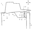
- FIG. 1 is a schematic cross-sectional view of a front structure of a vehicle;
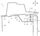
- FIG. 5 is a schematic longitudinal sectional view of the vehicle corresponding to the VI-VI line cross section of FIG. 4; 1 is a schematic cross-sectional view of a vehicle front structure to which a load is applied from the vehicle width direction;
- FIG. 1 A mode for carrying out the present invention will be described below with reference to FIGS. 1 to 7.
- FIG. 1 arrows indicating the front-rear direction, the left-right direction, and the up-down direction of the vehicle are shown as appropriate, and the left-right direction corresponds to the vehicle width direction. 1, 2, 4, 5 and 7, the left side of the vehicle is omitted. 2 to 7 show the main components of the front structure of the vehicle, and the illustration of other members is omitted.
- the front portion of the vehicle 2 is provided with door openings 5 that are opened and closed by front doors 4 on both left and right sides. Pillar members 10 (details will be described later) are erected at the front edges of the left and right door openings 5, respectively, and the left and right pillar members 10 support the front portion of a roof panel (not shown).
- a front glass FG is provided at a position surrounded by the left and right pillar members 10 and the roof panel.
- Each pillar member 10 has a pillar strut portion 11 below the beltline BR of the front door 4 covered by the fender panel 6 .
- An engine hood 7 is provided between the left and right fender panels 6 so that the engine room ER of the vehicle 2 can be opened and closed.
- a dash panel 8 is provided in the form of a vertical wall extending in the vehicle width direction (horizontal direction) to partition them.
- a cowl member 20 is provided on the dash panel 8 so as to extend in the vehicle width direction (horizontal direction). Then, the ends (right end and left end) of the cowl member 20 in the vehicle width direction are fixed to the left and right pillar strut portions 11 located on the outer side in the vehicle width direction and to the upper members (not shown) constituting the left and right side walls of the engine room.
- the cowl member 20 shown in FIG. 3 is formed in a groove shape from an inclined front wall portion 23, a substantially U-shaped water channel portion 24, and an inclined rear wall portion 25, and a dash panel is provided below the inclined front wall portion 23. 8 is joined.
- the water channel portion 24 and the inclined rear wall portion 25 of the cowl member 20 located on the rear side of the dash panel 8 are arranged on the passenger compartment R side.
- the cowl member 20 is provided with a front flange portion 23f on the front side of the upper end of the inclined front wall portion 23.
- the front flange portion 23f supports a cowl louver 28, which is a vehicle body exterior component extending in the vehicle width direction. .
- a rear flange portion 25f is provided on the rear side of the upper end of the inclined rear wall portion 25 of the cowl member 20, and the lower flange portion 27f of the cowl upper panel 27 is connected to the rear flange portion 25f.
- a cowl upper panel 27 forming the upper portion of the cowl member 20 is configured to support the lower portion of the windshield FG by having its upper surface adhered to the lower rear surface of the windshield FG with an adhesive or the like.
- the lower end of the windshield FG is fixed by a fixing member 29 to the glass connection wall 28a at the rear edge of the cowl louver 28. As shown in FIG.
- a pipe-shaped instrument panel reinforcement 30 is provided in the vehicle compartment R shown in FIG. 2 so as to extend in the vehicle width direction.
- the instrument panel reinforcement 30 is arranged at the vehicle rear position of the cowl member 20 described above while being arranged inside the instrument panel (not shown).
- the ends (right end and left end) of the instrument panel reinforcement 30 in the vehicle width direction are attached to the left and right pillar strut portions 11 located outside in the vehicle width direction via brackets 31 which will be described later.
- the instrument panel reinforcement 30 is provided with a beam-like brace 32 that connects a portion that supports the steering (not shown) and the upper part of the dash panel 8 (in FIG. shown).
- the front structure of the vehicle 2 includes the cowl member 20, the instrument panel reinforcement 30, and the pillar member 10 (details will be described later), as described above.
- Each pillar member 10 is provided with a gusset member 40 to which the instrument panel reinforcement 30 is attached.
- the deformation of the cowl member 20 absorbs the impact load applied to the windshield FG from the front of the vehicle, it is desirable to secure the amount of downward deformation of the cowl member 20 .
- the amount of downward deformation of the cowl member 20 is ensured while ensuring the strength around the mounting location of the instrument panel reinforcement 30 by the configuration described later.
- the details of the pillar member 10 and the gusset member 40, and the arrangement relationship among the gusset member 40, the cowl member 20, and the instrument panel reinforcement 30 will be described below.
- the right pillar member 10 shown in FIG. 4 has the above-described pillar support portion 11 and a gusset member 40 provided on the pillar support portion 11 .
- the pillar strut portion 11 is formed in a tubular shape from a pillar inner panel 12 and a pillar outer panel 13.
- the pillar inner panel 12 has a surface on the inner side in the vehicle width direction (the left surface in FIG. 5). ) is configured.
- the pillar strut portion 11 of the pillar member 10 is reinforced on the inner side in the vehicle width direction by a gusset member 40 which will be described later. That is, the pillar inner panel 12 is raised (reinforced) by overlapping the gusset member 40 on the inner side in the vehicle width direction, and the strength against the load applied from the inner side in the vehicle width direction is ensured.
- the gusset member 40 shown in FIG. 4 includes a front wall portion 41 facing forward, a rear wall portion 42 facing rearward, a left wall portion 43 facing left, an upper wall portion 44 facing upward, and a wall portion 44 facing downward. It is formed in the shape of a hollow box from the lower wall portion 45, and the right side is open.
- the front wall portion 41 gradually inclines to the right as it goes forward, and the rear wall portion 42 and the left wall portion 43 are formed in a vertical wall shape that stands up in the vertical direction of the vehicle.
- the upper wall portion 44 and the lower wall portion 45 shown in FIG. 6 are formed in a lateral wall shape extending in the vehicle width direction (horizontal direction).
- the edges on the pillar member 10 side are bent to form a flange portion 46.
- This flange portion It is welded or fastened to the pillar inner panel 12 at 46 .
- the gusset member 40 is fixed to the pillar inner panel 12 and arranged at the vehicle rear position of the cowl member 20 described above. That is, the gusset member 40 has a shorter dimension in the vehicle front-rear direction than the pillar inner panel 12 , and the front end of the gusset member 40 (the front flange portion 46 provided on the front wall portion 41 ) is aligned with the cowl member 20 rearward of the vehicle. It is fixed to the pillar inner panel 12 at the position.
- the gusset member 40 has a rear wall portion 42 facing the rear of the vehicle, which serves as a mounting wall portion 50 for mounting the instrument panel reinforcement 30 thereon.
- the mounting wall portion 50 is positioned on the rear side of the pillar inner panel 12, as shown in FIG. are provided with an opening.
- the mounting wall portion 50 is supported by an upper wall portion 44 and a lower wall portion 45 extending toward the pillar support portion 11 along the upper and lower peripheral edges thereof. , 45 are fixed to the pillar inner panel 12 at the flange portions 46 thereof.
- the gusset member 40 has the mounting wall portion 50, the upper wall portion 44, and the lower wall portion 45 formed in a tower shape, thereby ensuring strength against a load applied from the inside in the vehicle width direction.
- the pillar inner panel 12 of the pillar strut portion 11 has upper and lower bead portions 14 extending in the direction connecting the cowl member 20 and the gusset member 40 (vehicle front-rear direction in each figure). , 15 are formed.
- the upper and lower bead portions 14 and 15 are formed by deforming the pillar inner panel 12 in a direction to locally bulge in the vehicle width direction (for example, the left side, which is the inner side in the vehicle width direction).
- the upper bead portion 14 is formed at a height position that substantially coincides with the height position of the upper fastening hole 51 of the mounting wall portion 50 shown in FIGS. deferred. That is, as shown in FIG.
- the upper bead portion 14 straddles the front end of the gusset member 40 (the front flange portion 46 provided on the front wall portion 41) from the fixing point X of the cowl member 20 to the pillar member 10. It extends behind the vehicle.
- the lower bead portion 15 shown in FIGS. 4 and 6 is formed at a height position substantially matching the height position of the lower fastening hole 52 of the mounting wall portion 50 .
- the lower bead portion 15 extends from the fixing point X of the cowl member 20 to the pillar member 10 across the front end of the gusset member 40 to near the middle of the gusset member 40 in the front-rear direction. Furthermore, by aligning the height positions of the upper and lower bead portions 14, 15 shown in FIG. can be ensured more reliably.
- the vehicle width direction end portion (right end in FIG. 2 ) of the instrument panel reinforcement 30 is fixed to the gusset member 40 of the pillar inner panel 12 of the pillar member 10 .
- a bracket 31 is attached to the end of the instrument panel reinforcement 30 in the vehicle width direction, as shown in FIG. It is fixed by a fastener BT.
- the instrument panel reinforcement 30 is supported by the gusset member 40 at its vehicle width direction end portion, thereby extending in the vehicle width direction at the vehicle rear position of the cowl member 20 .
- the gusset member 40 is fixed to the pillar inner panel 12 at the vehicle rear position of the cowl member 20 as described above.
- a space portion 60 is formed at a position surrounded by the cowl member 20, the pillar member 10, and the gusset member 40, the inner side in the vehicle width direction (the left side in each drawing) being open.
- the dimension of the space 60 in the longitudinal direction of the vehicle is not particularly limited as long as the cowl member 20 can be deformed downward. It should be set.
- another space is formed on the left side of the front part of the vehicle so as to be bilaterally symmetrical with the space 60 .
- the instrument panel reinforcement 30 vibrates in the vehicle width direction due to vibration or the like transmitted from the road surface when the vehicle 2 is running (see white arrow A1 in FIG. 7).
- the load applied from the instrument panel reinforcement 30 is received by the pillar member 10 and the gusset member 40 , that is, the portion raised to reinforce the pillar inner panel 12 .
- the instrument panel reinforcement 30 is less likely to move in the vehicle width direction, thereby contributing to securing the steering rigidity. becomes.
- the gusset member 40 has the mounting wall portion 50, the upper wall portion 44, and the lower wall portion 45 shown in FIG. It is
- the upper and lower bead portions 14 and 15 extend rearward of the vehicle from around the fixing point X of the cowl member 20 across the front flange portion 46 of the gusset member 40 . Therefore, even when a load is applied to the pillar member 10 from the front end (front flange portion 46 ) of the gusset member 40 , the deformation of the pillar member 10 , especially the front end position of the gusset member 40 and the fixing point X of the cowl member 20 . You can suppress the deformation of the per.
- the impact load IL applied to the windshield FG from the front of the vehicle is absorbed by the downward deformation of the cowl member 20 that supports the windshield FG.
- the space 60 at the position surrounded by the cowl member 20, the pillar member 10 and the gusset member 40, it is possible to secure the amount of downward deformation of the cowl member 20. . Furthermore, in the above configuration, since the amount of deformation of the cowl member 20 is secured by the space portion 60, there is no need to change the shape of the cowl member 20 that affects the design of the vehicle 2, and the degree of freedom in selecting the design of the vehicle 2 is ensured. can be done.
- the gusset member 40 is provided so as to overlap the inner side of the pillar member 10 in the vehicle width direction, and the strength against the load applied from the inner side of the pillar member 10 in the vehicle width direction is ensured. It has a configuration that contributes to ensuring the strength around the mounting location.
- a space 60 is provided at a position surrounded by the cowl member 20, the pillar member 10, and the gusset member 40, where there is no member that reinforces the cowl member 20, thereby reducing the amount of downward deformation of the cowl member 20. can be ensured. Therefore, according to the present embodiment, it is possible to secure the amount of downward deformation of the cowl member 20 while securing the strength around the mounting location of the instrument panel reinforcement 30 .
- the mounting wall portion 50 for mounting the instrument panel reinforcement 30 is disposed on the pillar member 10 in a state supported by the wall portions 44 and 45 extending toward the pillar member 10. Therefore, the instrument panel reinforcement 30 It is a configuration that contributes to securing the strength around the mounting location.
- the pillar member 10 is reinforced by the bead portions 14 and 15 formed between the gusset member 40 and the cowl member 20, thereby further ensuring the strength around the mounting location of the instrument panel reinforcement 30. becomes.
- the vehicle front structure of the present embodiment is not limited to the embodiment described above, and may take various other embodiments.
- the gusset member can be box-shaped, column-shaped, or tubular (hollow or dense) with a plurality of walls, any of which walls can serve as mounting walls.
- the mounting wall portion can be set at an appropriate position (wall portion), and in particular, the mounting wall portion can be set at any of the rear wall portion, the upper wall portion, and the lower wall portion. is.
- the gusset member when the gusset member is formed in a turret shape (U-shaped cross section), it is sufficient to have a mounting wall portion and a wall portion for supporting this, and other wall portions can be omitted.
- various methods such as welding can be adopted in addition to fastening.
- the bead portion may extend in the direction connecting the cowl member and the gusset member, and may be generally linear, may be slanted or curved, and may be formed in a grid pattern as necessary. It is also possible to Also, the number of bead portions to be formed may be singular or plural (three or more), and the formation position thereof can be set as appropriate, or may be omitted.
- the bead portion can be formed by raising the pillar inner panel either outwardly or inwardly in the vehicle width direction, or by fixing a separate member to the pillar inner panel.
- the configuration of the cowl member and the instrument panel reinforcement has been illustrated in the present embodiment, the configuration of the cowl member and the instrument panel reinforcement is not intended to be limited. That is, the shape and dimensions of the cowl member can be appropriately set so as to support an appropriate position on the lower portion of the windshield. Also, the shape and dimensions of the instrument panel reinforcement can be appropriately set so as to support the steering wheel. Also, the configuration of the vehicle can be changed as appropriate.
Landscapes
- Engineering & Computer Science (AREA)
- Chemical & Material Sciences (AREA)
- Combustion & Propulsion (AREA)
- Transportation (AREA)
- Mechanical Engineering (AREA)
- Body Structure For Vehicles (AREA)
Priority Applications (2)
| Application Number | Priority Date | Filing Date | Title |
|---|---|---|---|
| JP2022577824A JP7375959B2 (ja) | 2021-01-26 | 2021-01-26 | 車両の前部構造 |
| PCT/JP2021/002571 WO2022162724A1 (ja) | 2021-01-26 | 2021-01-26 | 車両の前部構造 |
Applications Claiming Priority (1)
| Application Number | Priority Date | Filing Date | Title |
|---|---|---|---|
| PCT/JP2021/002571 WO2022162724A1 (ja) | 2021-01-26 | 2021-01-26 | 車両の前部構造 |
Publications (1)
| Publication Number | Publication Date |
|---|---|
| WO2022162724A1 true WO2022162724A1 (ja) | 2022-08-04 |
Family
ID=82654270
Family Applications (1)
| Application Number | Title | Priority Date | Filing Date |
|---|---|---|---|
| PCT/JP2021/002571 Ceased WO2022162724A1 (ja) | 2021-01-26 | 2021-01-26 | 車両の前部構造 |
Country Status (2)
| Country | Link |
|---|---|
| JP (1) | JP7375959B2 (https=) |
| WO (1) | WO2022162724A1 (https=) |
Cited By (1)
| Publication number | Priority date | Publication date | Assignee | Title |
|---|---|---|---|---|
| JP2023077035A (ja) * | 2021-11-24 | 2023-06-05 | 株式会社Subaru | ステアリングビーム支持構造 |
Citations (3)
| Publication number | Priority date | Publication date | Assignee | Title |
|---|---|---|---|---|
| JPH0739271B2 (ja) * | 1986-09-26 | 1995-05-01 | マツダ株式会社 | 自動車の前部車体構造 |
| JP2005335579A (ja) * | 2004-05-27 | 2005-12-08 | Toyota Auto Body Co Ltd | 自動車の車体前部構造 |
| JP2019108026A (ja) * | 2017-12-19 | 2019-07-04 | トヨタ自動車株式会社 | 車両のフロントピラー構造 |
-
2021
- 2021-01-26 WO PCT/JP2021/002571 patent/WO2022162724A1/ja not_active Ceased
- 2021-01-26 JP JP2022577824A patent/JP7375959B2/ja active Active
Patent Citations (3)
| Publication number | Priority date | Publication date | Assignee | Title |
|---|---|---|---|---|
| JPH0739271B2 (ja) * | 1986-09-26 | 1995-05-01 | マツダ株式会社 | 自動車の前部車体構造 |
| JP2005335579A (ja) * | 2004-05-27 | 2005-12-08 | Toyota Auto Body Co Ltd | 自動車の車体前部構造 |
| JP2019108026A (ja) * | 2017-12-19 | 2019-07-04 | トヨタ自動車株式会社 | 車両のフロントピラー構造 |
Cited By (1)
| Publication number | Priority date | Publication date | Assignee | Title |
|---|---|---|---|---|
| JP2023077035A (ja) * | 2021-11-24 | 2023-06-05 | 株式会社Subaru | ステアリングビーム支持構造 |
Also Published As
| Publication number | Publication date |
|---|---|
| JP7375959B2 (ja) | 2023-11-08 |
| JPWO2022162724A1 (https=) | 2022-08-04 |
Similar Documents
| Publication | Publication Date | Title |
|---|---|---|
| JP6973328B2 (ja) | 車両の前部車体構造 | |
| JP7677070B2 (ja) | 車両の側部車体構造 | |
| JPH1045034A (ja) | 車体前部構造 | |
| JP5321334B2 (ja) | 車両のカウル部構造 | |
| JP2006206004A (ja) | ウインドシールドガラスの支持構造 | |
| EP3613655B1 (en) | Front body structure for vehicle and method of providing the same | |
| JP5156729B2 (ja) | サブフレーム構造 | |
| JP2010083187A (ja) | 車体前部構造 | |
| JP2012046131A (ja) | パーティションサイド部の構造 | |
| JP6973327B2 (ja) | 車両の前部車体構造 | |
| JP3776003B2 (ja) | 自動車のフロントピラー部構造 | |
| JP2008260331A (ja) | 自動車の前部構造 | |
| JP2020029163A (ja) | 車両の前部車体構造 | |
| WO2022162724A1 (ja) | 車両の前部構造 | |
| JP5076718B2 (ja) | 自動車の前部車体構造 | |
| JP4214629B2 (ja) | 車両の前部車体構造 | |
| JP3818856B2 (ja) | 車両用ドアのベルトライン補強構造 | |
| JP2009035106A (ja) | 自動車の前部車体構造 | |
| JP3978942B2 (ja) | サスペンションメンバ取付部車体構造 | |
| JP3640240B2 (ja) | 車両用フロントピラーのドアヒンジ部補強構造 | |
| JP2009101956A (ja) | 自動車のカウル構造 | |
| JP4998798B2 (ja) | 側部車体構造 | |
| KR100445876B1 (ko) | 자동차 카울부의 보강구조 | |
| JP2010111257A (ja) | 車両のルーフ構造 | |
| JP3726319B2 (ja) | 自動車の前部車体構造 |
Legal Events
| Date | Code | Title | Description |
|---|---|---|---|
| 121 | Ep: the epo has been informed by wipo that ep was designated in this application |
Ref document number: 21921659 Country of ref document: EP Kind code of ref document: A1 |
|
| ENP | Entry into the national phase |
Ref document number: 2022577824 Country of ref document: JP Kind code of ref document: A |
|
| WWE | Wipo information: entry into national phase |
Ref document number: 202317018151 Country of ref document: IN |
|
| NENP | Non-entry into the national phase |
Ref country code: DE |
|
| 122 | Ep: pct application non-entry in european phase |
Ref document number: 21921659 Country of ref document: EP Kind code of ref document: A1 |