WO2022154120A1 - 印画物の製造方法、印画物及び熱転写シート - Google Patents
印画物の製造方法、印画物及び熱転写シート Download PDFInfo
- Publication number
- WO2022154120A1 WO2022154120A1 PCT/JP2022/001399 JP2022001399W WO2022154120A1 WO 2022154120 A1 WO2022154120 A1 WO 2022154120A1 JP 2022001399 W JP2022001399 W JP 2022001399W WO 2022154120 A1 WO2022154120 A1 WO 2022154120A1
- Authority
- WO
- WIPO (PCT)
- Prior art keywords
- layer
- transfer sheet
- thermal transfer
- base material
- printed matter
- Prior art date
- Legal status (The legal status is an assumption and is not a legal conclusion. Google has not performed a legal analysis and makes no representation as to the accuracy of the status listed.)
- Ceased
Links
Images





Classifications
-
- B—PERFORMING OPERATIONS; TRANSPORTING
- B41—PRINTING; LINING MACHINES; TYPEWRITERS; STAMPS
- B41M—PRINTING, DUPLICATING, MARKING, OR COPYING PROCESSES; COLOUR PRINTING
- B41M5/00—Duplicating or marking methods; Sheet materials for use therein
- B41M5/26—Thermography ; Marking by high energetic means, e.g. laser otherwise than by burning, and characterised by the material used
- B41M5/382—Contact thermal transfer or sublimation processes
- B41M5/38207—Contact thermal transfer or sublimation processes characterised by aspects not provided for in groups B41M5/385 - B41M5/395
-
- B—PERFORMING OPERATIONS; TRANSPORTING
- B41—PRINTING; LINING MACHINES; TYPEWRITERS; STAMPS
- B41M—PRINTING, DUPLICATING, MARKING, OR COPYING PROCESSES; COLOUR PRINTING
- B41M3/00—Printing processes to produce particular kinds of printed work, e.g. patterns
- B41M3/06—Veined printings; Fluorescent printings; Stereoscopic images; Imitated patterns, e.g. tissues, textiles
-
- B—PERFORMING OPERATIONS; TRANSPORTING
- B41—PRINTING; LINING MACHINES; TYPEWRITERS; STAMPS
- B41M—PRINTING, DUPLICATING, MARKING, OR COPYING PROCESSES; COLOUR PRINTING
- B41M5/00—Duplicating or marking methods; Sheet materials for use therein
- B41M5/26—Thermography ; Marking by high energetic means, e.g. laser otherwise than by burning, and characterised by the material used
- B41M5/382—Contact thermal transfer or sublimation processes
-
- B—PERFORMING OPERATIONS; TRANSPORTING
- B41—PRINTING; LINING MACHINES; TYPEWRITERS; STAMPS
- B41M—PRINTING, DUPLICATING, MARKING, OR COPYING PROCESSES; COLOUR PRINTING
- B41M5/00—Duplicating or marking methods; Sheet materials for use therein
- B41M5/26—Thermography ; Marking by high energetic means, e.g. laser otherwise than by burning, and characterised by the material used
- B41M5/40—Thermography ; Marking by high energetic means, e.g. laser otherwise than by burning, and characterised by the material used characterised by the base backcoat, intermediate, or covering layers, e.g. for thermal transfer dye-donor or dye-receiver sheets; Heat, radiation filtering or absorbing means or layers; combined with other image registration layers or compositions; Special originals for reproduction by thermography
-
- B—PERFORMING OPERATIONS; TRANSPORTING
- B41—PRINTING; LINING MACHINES; TYPEWRITERS; STAMPS
- B41M—PRINTING, DUPLICATING, MARKING, OR COPYING PROCESSES; COLOUR PRINTING
- B41M2205/00—Printing methods or features related to printing methods; Location or type of the layers
- B41M2205/30—Thermal donors, e.g. thermal ribbons
-
- B—PERFORMING OPERATIONS; TRANSPORTING
- B41—PRINTING; LINING MACHINES; TYPEWRITERS; STAMPS
- B41M—PRINTING, DUPLICATING, MARKING, OR COPYING PROCESSES; COLOUR PRINTING
- B41M2205/00—Printing methods or features related to printing methods; Location or type of the layers
- B41M2205/32—Thermal receivers
-
- B—PERFORMING OPERATIONS; TRANSPORTING
- B41—PRINTING; LINING MACHINES; TYPEWRITERS; STAMPS
- B41M—PRINTING, DUPLICATING, MARKING, OR COPYING PROCESSES; COLOUR PRINTING
- B41M7/00—After-treatment of prints, e.g. heating, irradiating, setting of the ink, protection of the printed stock
- B41M7/009—After-treatment of prints, e.g. heating, irradiating, setting of the ink, protection of the printed stock using thermal means, e.g. infrared radiation, heat
Definitions
- This disclosure relates to a method for manufacturing a printed matter, a printed matter, and a thermal transfer sheet.
- the printed matter produced by the thermal transfer method has a wide variety of uses, for example, it is used for a card having a face photograph such as an ID card and a credit card, a composite photograph in an amusement facility, a trading card, and the like.
- the method for producing a printed matter of the present disclosure includes a step of preparing a thermal transfer sheet having a substrate and a transfer layer provided on one surface side of the substrate and having a layer containing foamed particles, and the thermal transfer.
- the printed matter of the present disclosure includes a transferred body and a laminated body provided on the transferred body and in which a plurality of transfer layers are laminated, and the plurality of the transfer layers are arranged in order from the transferred body side. It has a laminated adhesive layer and a layer containing foamed particles.
- the thermal transfer sheet of the present disclosure includes a base material and a plurality of transfer layers provided in a surface-sequential manner on one surface of the base material, and the plurality of transfer layers are each one of the base materials. It has a layer containing foam particles and an adhesive layer that are laminated in order from the surface side.
- thermal transfer sheet which concerns on embodiment. It is a process sectional view explaining the manufacturing method of a printed matter. It is a process sectional view explaining the manufacturing method of a printed matter. It is a process sectional view explaining the manufacturing method of a printed matter. It is a process sectional view explaining the manufacturing method of a printed matter. It is a process sectional view explaining the manufacturing method of the printed matter by a comparative example. It is a process sectional view explaining the manufacturing method of the printed matter by a comparative example. It is a process sectional view explaining the manufacturing method of the printed matter which concerns on another embodiment. It is a top view of the thermal transfer sheet. It is a process sectional view explaining the manufacturing method of the printed matter which concerns on another embodiment.
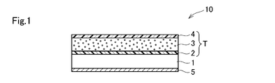
- FIG. 1 is a cross-sectional view of a thermal transfer sheet according to an embodiment of the present invention.
- the thermal transfer sheet 10 is provided with a transfer layer T on one surface of the base material 1 and a back layer 5 on the other surface.
- the transfer layer T has a release layer 2, a foam layer 3, and an adhesive layer 4 that are laminated in order from the base material 1 side.
- the foamed layer 3 is a foamed particle-containing layer containing unfoamed foamed particles.
- the foamed particles have an outer shell made of a thermoplastic resin and a foaming agent contained in the outer shell and vaporized by heating. Therefore, the foamed particles expand by heating.
- the first resin of the release layer 2 and the adhesive layer 4 has a higher glass transition temperature than the first binder resin of the foam layer 3.
- the first resin is the resin having the highest blending ratio among the resins contained in the release layer 2 and the adhesive layer 4.
- the first binder resin is a binder resin having the highest blending ratio among the binder resins contained in the foam layer 3.
- a known thermal transfer printer having a thermal head is used so that the adhesive layer 4 of the thermal transfer sheet 10 and the transferred body 6 (see FIG. 2) face each other with the thermal transfer sheet 10 and the transferred object. Overlay with body 6. Then, the thermal transfer sheet 10 is heated from the back layer 5 side in a predetermined pattern to transfer the first transfer layer T (T1) onto the transferred body 6.
- the transfer layer T transferred from the thermal transfer sheet 10 onto the transfer body 6 includes an adhesive layer 4, a foam layer 3, and a release layer 2, and the release layer 2 does not remain on the base material 1 of the thermal transfer sheet 10. At this time, the thermal energy applied to the thermal transfer sheet 10 is such that the transferred foam layer 3 does not expand in the plane direction.
- the transfer pattern includes a straight line or curved line portion having a line width W0.
- the transfer body 6 is not particularly limited to a plastic card base material, paper, or the like. Further, the shape of the transferred body 6 may be a flat surface or a curved surface.
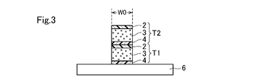
- the same thermal transfer sheet 10 or a different thermal transfer sheet 10 is superposed on the transferred body 6 to which the transfer layer T1 is transferred, and the thermal transfer sheet 10 is heated from the back layer 5 side in the same pattern.
- the second transfer layer T (T2) is transferred onto the first transfer layer T1 to form a laminated body in which the transfer layers T1 and T2 are laminated.
- an image (not shown) is formed on the transferred body 6 provided with the laminated body of the transfer layers T1 and T2.
- the image forming method is not particularly limited, and a sublimation transfer method, a melt transfer method, an inkjet method, or the like can be used.
- the sublimation transfer method and the inkjet method it is preferable to transfer the receiving layer onto the transfer target 6 so as to cover the transfer layers T1 and T2, and then transfer the coloring material to form an image.
- the protective layer may be transferred after image formation.
- an intermediate transfer medium may be used to transfer the layer on which the image is formed onto the transferred body 6 provided with the laminated body.
- the transferred body 6 is heated using a heating device such as a heat roller, an oven, or a thermal head.
- a heating device such as a heat roller, an oven, or a thermal head.
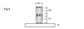
- the foamed particles in the foamed layer 3 of the transfer layers T1 and T2 expand. Due to the expansion of the foamed particles, the foamed layer 3 expands not only in the vertical direction (height direction) but also in the horizontal direction.
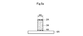
- FIGS. 5a and 5b show a method of manufacturing a printed matter according to a comparative example.
- a transfer layer having an adhesive layer 4A, a foam layer 3A, and a release layer 2A laminated on the transferred body 6A is transferred in a line pattern having a line width W0.
- the thickness of the foam layer 3A is about twice the thickness of the foam layer 3 described above.
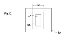
- the foamed particles in the foamed layer 3A expand as shown in FIGS. 5b and 12. Due to the expansion of the foamed particles, the foamed layer 3A also expands in the horizontal direction.
- the foamed layer 3A has a larger thickness (volume) per layer than the above-mentioned foamed layer 3, and the amount of expansion in the horizontal direction is particularly large in the central portion in the thickness direction.
- the line width W2 after expansion is larger than the line width W1 in FIGS. 4 and 11, and it is difficult to express a fine uneven pattern.
- the transfer layer T is transferred twice, and the two foam layers 3 are separated by a resin layer (release layer 2 and / or adhesive layer 4) having a high glass transition temperature, and the foam layer is per layer.
- a resin layer release layer 2 and / or adhesive layer 4 having a high glass transition temperature
- the foam layer is per layer.
- FIG. 6 shows a configuration in which the transfer layer T is transferred three times and the three transfer layers T1 to T3 are laminated.
- the transfer of the transfer layer T and the image formation may be performed by the same printer or may be performed by different printers.
- the thermal transfer sheet for transferring the transfer layer T and the thermal transfer sheet for transferring the coloring material may be integrated or may be separate.
- Transfer layers having different thicknesses of the foamed particle-containing layers may be provided in a surface-sequential manner on one thermal transfer sheet.
- a first thermal transfer sheet for transferring the transfer layer T for example, a first thermal transfer sheet for transferring the transfer layer T, a second thermal transfer sheet for transferring the coloring material, and a third thermal transfer sheet for transferring the receiving layer are prepared. ..
- the transfer layer T is provided on the first base material.
- the second thermal transfer sheet is provided with a coloring material layer on the second base material.
- the third thermal transfer sheet is provided with a receiving layer on the third base material.
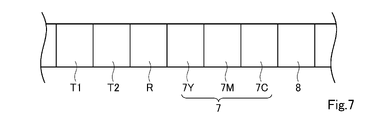
- FIG. 7 is a plan view of the thermal transfer sheet when the thermal transfer sheet for transferring the transfer layer T and the thermal transfer sheet for transferring the coloring material are integrated (a single ribbon). ..
- the thermal transfer sheet has transfer layers T1 and T2, a transfer type receiving layer R, a coloring material layer 7, and a protective layer 8 provided on one surface of the base material in a surface-sequential manner.
- the color material layer 7 includes a yellow color material layer 7Y containing a yellow color material, a magenta color material layer 7M containing a magenta color material, and a cyan color material layer containing a cyan color material, which are sequentially provided on the surface.
- Has 7C The coloring material contained in the yellow color material layer 7Y, the magenta color material layer 7M, and the cyan color material layer 7Y is, for example, a sublimation dye.
- the transfer layers T1 and T2 are heated in the same pattern in order, and the transfer layers T1 and T2 are transferred and laminated on the transferred body. Subsequently, the transcription type receiving layer R is transferred onto the transferred body. Next, the yellow color material layer 7Y, the magenta color material layer 7M, and the cyan color material layer 7Y are transferred in order to form an image on the receiving layer R on the transfer target. Then, the protective layer 8 is heated to transfer the protective layer 8 onto the receiving layer R on which the image is formed.
- the transfer type receiving layer R can be omitted.
- the transfer layer T (foam layer 3) is laminated and the thickness (volume) of the foam layer 3 per layer is reduced to suppress the expansion amount in the horizontal direction
- the transfer layer T may be transferred by a dot pattern (halftone dots) instead of a solid pattern to suppress the width of the foam layer 3 in the horizontal direction.
- W0 be the distance between the transfer layers T at both ends.
- the foamed particles in the foamed layer 3 expand due to the heat treatment, and as shown in FIG. 8b, the foamed layers 3 of the adjacent dot-shaped transfer layers T are bonded to each other to form a line portion having a line width W3.
- the transfer layer T By transferring the transfer layer T in a dot pattern, the volume of each foam layer 3 is reduced, the amount of expansion in the horizontal direction is suppressed, the line width W3 is slightly larger than W0, and a high-definition uneven pattern is formed. Can be expressed.
- the transfer layers T (T1, T2) may be transferred so as to have a dot pattern and two layers are laminated.
- the heat treatment as shown in FIG. 9b, the foam layers 3 of the adjacent dot-shaped transfer layers T1 are bonded to each other, and the foam layers 3 of the transfer layer T2 are bonded to each other.
- a higher-definition uneven pattern can be expressed.
- the positions of the dot pattern of the first transfer layer T1 and the dot pattern of the second transfer layer T2 may be shifted, or the size (width) may be changed.
- the foamed particles are expanded after the image is formed, but the image may be formed after the expanded particles are expanded.
- the transfer layers T1 and T2 may be transferred onto the transferred body 6 (receptive layer) to form a laminate.
- a release layer may be provided between 1 and the transfer layer T. That is, the release layer, the release layer, the foam layer, and the adhesive layer may be laminated in this order on one surface of the base material 1 of the thermal transfer sheet 10.
- the release layer may be omitted from the transfer layer T, and the release layer, the foam layer, and the adhesive layer may be laminated in this order on one surface of the base material 1 of the thermal transfer sheet 10. After the transfer layer T is transferred onto the transfer target 6, the release layer remains on the base material 1.
- the base material 1 of the thermal transfer sheet 10 is not limited in any way, and conventionally known ones in the field of thermal transfer sheets can be appropriately selected and used. Examples include polyester, polyphenylene sulfide, polyether ketone, polyether sulfone, polypropylene, polycarbonate, cellulose acetate, polyethylene derivatives, polyvinyl chloride, polyvinylidene chloride, polystyrene, polyamide, polyimide, polymethylpentene or ionomer, etc. Examples include stretched or unstretched films of plastic.
- the polyester preferably has high heat resistance, and examples thereof include polyethylene terephthalate, polyethylene naphthalate, and polybutylene terephthalate. Further, a composite film in which two or more kinds of these materials are laminated can also be used.
- the thickness of the base material 1 is not particularly limited, but is preferably in the range of 2 ⁇ m or more and 10 ⁇ m or less.
- the release layer 2 is provided at a position closest to the base material 1 of the transfer layer T.
- the binder resin constituting the release layer include cellulose derivatives such as ethyl cellulose, nitrocellulose and cellulose acetate, acrylic resins such as polymethylmethacrylate, ethylpolymethacrylate and butylpolyacrylate, polyvinyl chloride and vinyl chloride.
- Thermoplastic resins such as vinyl acetate copolymers and vinyl resins such as polyvinyl butyral, saturated or unsaturated polyesters, polyurethane resins, thermosetting epoxy-amino copolymers, and thermosetting alkyd-amino copolymers.
- thermosetting resins silicone waxes, silicone resins, silicone-modified resins, fluororesins, fluorine-modified resins, polyvinyl alcohols, and the like, which are exemplified by (thermosetting aminoalkyd resins).
- the glass transition temperature (Tg) of the first resin of the release layer is preferably higher than the glass transition temperature of the first binder resin of the foam layer, which will be described later.
- Tg is a value obtained by differential scanning calorimetry (DSC) in accordance with JIS K7121.
- the foamed layer 3 contains foamed particles and a binder resin.
- the foamed particles are heat-expandable microspheres composed of an outer shell (shell) made of a thermoplastic resin and a foaming agent (core) contained therein.
- the foamed particles have a core-shell structure and exhibit thermal expansion properties (the property that the entire microspheres expand by heating) as the whole microspheres.
- the thermoplastic resin is a polymer of polymerizable components.
- the polymerizable component means a monomer having at least one polymerizable group in the molecule, and is a component that becomes a thermoplastic resin that forms an outer shell of foamed particles by polymerization.
- the polymerizable component includes a non-crosslinkable monomer having one reactive carbon-carbon double bond (hereinafter, simply referred to as a non-crosslinkable monomer), and two or more reactive carbon-carbon double bonds. Examples thereof include crosslinkable monomers having (hereinafter, simply referred to as crosslinkable monomers).
- the crosslinkable monomer allows the bridging structure to be introduced into the polymer.
- the reactive carbon-carbon double bond here means a carbon-carbon double bond exhibiting radical reactivity, and is not a carbon-carbon double bond in an aromatic ring such as a benzene ring or a naphthalene ring, but a vinyl.
- Examples thereof include carbon-carbon double bonds contained in a group, a (meth) acryloyl group, an allyl group, a vinylene group and the like.
- the (meth) acryloyl group shall mean an acryloyl group or a methacryloyl group.
- the foaming agent is a component that vaporizes when heated.
- the foaming agent is not particularly limited, but for example, propane, (iso) butane, (iso) pentane, (iso) hexane, (iso) heptane, (iso) octane, (iso) nonane, (iso) decane, ( Hydrocarbons having 3 to 13 carbon atoms such as iso) undecane, (iso) dodecane, and (iso) tridecane, hydrocarbons having more than 13 carbon atoms and 20 or less carbon atoms such as (iso) hexadecane and (iso) eikosan, pseudocumene, petroleum ether , Initial distilling point 150 ° C or higher and 260 ° C or lower and / or distillation range 70 ° C or higher and 360 ° C or lower, hydrocarbons such as petroleum distillates such as normal paraffin and isoparaffin, methyl chloride,
- Hydrocarbon halides having 1 to 12 carbon atoms fluorine-containing compounds such as hydrofluoroether, alkyl groups having 1 to 5 carbon atoms such as tetramethylsilane, trimethylethylsilane, trimethylisopropylsilane, and trimethyl-n-propylsilane.
- fluorine-containing compounds such as hydrofluoroether
- alkyl groups having 1 to 5 carbon atoms such as tetramethylsilane, trimethylethylsilane, trimethylisopropylsilane, and trimethyl-n-propylsilane.
- Examples thereof include silanes having silanes, azodicarboxylic amides, N, N'-dinitrosopentamethylenetetramine, 4,4'-oxybis (benzenesulfonylhydrazide) and other compounds that generate gas by thermal decomposition by heating.
- the foaming agent may be composed of one kind of compound or a mixture of two or more kinds of compounds.
- the foaming agent may be linear, branched or alicyclic, and is preferably an aliphatic one.
- the encapsulation rate of the foaming agent of the foamed particles is defined as a percentage of the weight of the enclosed foaming agent with respect to the weight of the foamed particles.
- the encapsulation rate of the foaming agent is not particularly limited, but is preferably 2% by weight or more and 50% by weight or less, and more preferably 10% by weight or more and 20% by weight or less with respect to the weight of the foamed particles.
- the expansion start temperature of the foamed particles is not particularly limited, but is preferably 70 ° C. or higher.
- the average particle size (D50) of the foamed particles is 5 ⁇ m or more and 30 ⁇ m or less.
- the average particle size (D50) can be measured by laser diffraction / scattering particle size distribution measurement.
- first binder resin contained in the foam layer examples include cellulose resin, vinyl resin, acrylic resin, polyester and the like, and polyester is particularly preferable.
- the glass transition temperature of the first binder resin is preferably lower than the glass transition temperature of the first resin of the release layer described above.
- the first binder resin contained in the foamed layer preferably has a high glass transition temperature, and preferably has a low ratio of the foaming agent in the foamed layer.
- the glass transition temperature of the first binder resin is preferably 40 ° C. or higher and 80 ° C. or lower, and the ratio of the foaming agent in the foam layer is preferably about 2: 8 to 4: 6.
- the first binder resin contained in the foamed layer preferably has a low glass transition temperature.
- the glass transition temperature of the first binder resin is preferably ⁇ 20 ° C. or higher and 20 ° C. or lower.
- the first binder resin is determined according to the shape required for the uneven pattern.
- the thickness of the foamed layer before the expanded particles expand is preferably 5 ⁇ m or more and 50 ⁇ m or less.
- the thickness of the foamed layer (the total thickness of the plurality of foamed layers) after the expanded particles are expanded is preferably 250 ⁇ m or more and 600 ⁇ m or less.
- An adhesive layer 4 is provided on the foam layer 3 in order to improve the adhesion between the transfer material and the transfer layer T.
- the material of the adhesive layer include cellulose derivatives such as ethyl cellulose and cellulose vinegar butyrate, styrene copolymers such as polystyrene and poly ⁇ -methyl styrene, acrylic resins such as polymethyl methacrylate, polyethyl methacrylate and polyethyl acrylate, and poly.
- examples thereof include vinyl chloride, polyvinyl acetate, vinyl chloride-vinyl acetate copolymer, vinyl resin such as polyvinyl butyral, polyester, nylon resin, epoxy resin and polyurethane. It is preferable that the glass transition temperature of the first resin of the adhesive layer is higher than the glass transition temperature of the first binder resin of the foamed layer.
- the material of the back layer 5 is not limited, and for example, a cellulose resin such as cellulose acetate butyrate or cellulose acetate propionate, a vinyl resin such as polyvinyl butyral or polyvinyl acetal, polymethyl methacrylate, ethyl polyacrylate, polyacrylamide, etc.
- a cellulose resin such as cellulose acetate butyrate or cellulose acetate propionate
- a vinyl resin such as polyvinyl butyral or polyvinyl acetal
- polymethyl methacrylate ethyl polyacrylate
- polyacrylamide etc.
- acrylic resins such as acrylonitrile-styrene copolymers
- natural or synthetic resins such as polyamide resins, polyamideimides, polyesters, polyurethanes, silicone-modified or fluorine-modified urethanes.
- the back layer may contain one of these resins alone or may contain two or more of these resins.
- the transfer-type receiving layer R shown in FIG. 7 has a receiving layer and an adhesive layer that are laminated in order from the base material side.
- the material of the receiving layer is not particularly limited, but it is preferable to use a binder resin in which the sublimation dye contained in the coloring material layer is easily dyed.
- binder resins include polyolefins such as polypropylene, halogenated resins such as polyvinyl chloride and vinylidene chloride, vinyl resins such as polyvinyl acetate and polyacrylic ester, polyesters such as polyethylene terephthalate and polybutylene terephthalate, and polystyrene. Examples thereof include polyamide, ionomer, and cellulose resin.
- the receiving layer may contain one of these binder resins alone, or may contain two or more of these binder resins.
- the thickness of the receiving layer is generally 1.0 ⁇ m or more and 10 ⁇ m or less, preferably 1.0 ⁇ m or more and 5.0 ⁇ m or less.
- the binder resin constituting the protective layer 8 examples include polyester, polyester urethane resin, polycarbonate, acrylic resin, epoxy resin, acrylic urethane resin, a resin obtained by silicone-modifying each of these resins, and a mixture of these resins. Can be mentioned.
- the protective layer may contain an ultraviolet absorbing resin or an active photocurable resin.
- the active light means a light that chemically acts on the active photocurable resin to promote polymerization, and specifically, visible light, ultraviolet rays, X-rays, electron beams, ⁇ rays, and ⁇ rays. It means line, ⁇ -ray, etc.
- a release layer may be provided between the base material and the protective layer in order to improve the transferability of the protective layer.
- thermo transfer sheet 1 A PET film having a thickness of 5 ⁇ m was used as a base material, and a coating liquid for a back layer having the following composition was applied to one surface of the base material and dried to form a back layer having a thickness of 1 ⁇ m. Further, a release layer having the following composition was applied to the other surface of the base material and dried to form a release layer having a thickness of 0.5 ⁇ m. Next, a foaming layer coating liquid 1 having the following composition was applied onto the peeling layer and dried to form a foaming layer having a thickness of 30 ⁇ m. Next, an adhesive layer coating liquid 1 having the following composition is applied onto the foam layer and dried to form an adhesive layer having a thickness of 2.5 ⁇ m. A thermal transfer sheet 1 in which the adhesive layers were laminated in this order was obtained.
- ⁇ Coating liquid for foam layer 1 5 parts by mass of foamed particles A (Matsumoto Microsphere (registered trademark) HF30D, Matsumoto Yushi Pharmaceutical Co., Ltd., foaming temperature: 115 ° C., average particle size: 14 ⁇ m) 5 parts by mass of polyester (Byronal (registered trademark) MD1930, Toyobo Co., Ltd., glass transition temperature: -10 ° C) ⁇ 23 parts by mass of water
- ⁇ Coating liquid for adhesive layer 1 5 parts by mass of polyester (Byronal (registered trademark) MD1930, Toyobo Co., Ltd., glass transition temperature: -10 ° C) ⁇ 15 parts by mass of water
- thermal transfer sheet 2 was produced in the same manner as the thermal transfer sheet 1 except that a foam layer having a thickness of 40 ⁇ m was formed by applying the foaming layer coating liquid 1 having the above composition on the release layer and drying it. did.
- thermal transfer sheet 3 is produced in the same manner as the thermal transfer sheet 1 except that a foam layer having a thickness of 20 ⁇ m is formed by applying the foaming layer coating liquid 1 having the above composition on the release layer and drying it. did.
- thermal transfer sheet 4 is the same as the thermal transfer sheet 1 except that an adhesive layer having a thickness of 2.5 ⁇ m is formed by applying the adhesive layer coating liquid 2 having the following composition on the foam layer and drying it. Was produced.
- thermal transfer sheet 5 is produced in the same manner as the thermal transfer sheet 4 except that a foam layer having a thickness of 30 ⁇ m is formed by applying the foaming layer coating liquid 2 having the following composition on the release layer and drying it. did.
- ⁇ Coating liquid for foam layer 2 > 5 parts by mass of foamed particles B (Matsumoto Microsphere (registered trademark) FN80GSD, Matsumoto Yushi Pharmaceutical Co., Ltd., foaming temperature 115 ° C., average particle size: 13 ⁇ m) ⁇ 5 parts by mass of polyester (Byronal (registered trademark) MD1930, Toyobo Co., Ltd.) ⁇ 23 parts by mass of water
- thermal transfer sheet 6 is produced in the same manner as the thermal transfer sheet 4 except that a foam layer having a thickness of 30 ⁇ m is formed by applying a foam layer coating liquid 3 having the following composition on the release layer and drying the layer. did.
- ⁇ Coating liquid for foam layer 3 5 parts by mass of foamed particles C (Matsumoto Microsphere (registered trademark) HF36D, Matsumoto Yushi Pharmaceutical Co., Ltd., foaming temperature 115 ° C., average particle size: 13 ⁇ m) ⁇ 5 parts by mass of polyester (Byronal (registered trademark) MD1930, Toyobo Co., Ltd.) ⁇ 23 parts by mass of water
- thermal transfer sheet 7 was produced in the same manner as the thermal transfer sheet 4 except that a foam layer having a thickness of 30 ⁇ m was formed by applying a foam layer coating liquid 4 having the following composition on the release layer and drying the layer. did.
- ⁇ Coating liquid for foam layer 4 5 parts by mass of foamed particles D (Matsumoto Microsphere (registered trademark) HF48D, Matsumoto Yushi Pharmaceutical Co., Ltd., foaming temperature 130 ° C., average particle size: 12 ⁇ m) ⁇ 5 parts by mass of polyester (Byronal (registered trademark) MD1930, Toyobo Co., Ltd.) ⁇ 23 parts by mass of water
- thermal transfer sheet 8 is produced in the same manner as the thermal transfer sheet 4 except that a foam layer having a thickness of 30 ⁇ m is formed by applying a foam layer coating liquid 5 having the following composition on the release layer and drying the layer. did.
- ⁇ Coating liquid for foam layer 5 Effervescent particles E 5 parts by mass (Matsumoto Microsphere (registered trademark) F36LVD, Matsumoto Yushi Pharmaceutical Co., Ltd., foaming temperature 115 ° C., average particle size: 16 ⁇ m) ⁇ 5 parts by mass of polyester (Byronal (registered trademark) MD1930, Toyobo Co., Ltd.) ⁇ 23 parts by mass of water
- thermal transfer sheet 9 is the same as the thermal transfer sheet 1 except that an adhesive layer having a thickness of 2.5 ⁇ m is formed by applying the adhesive layer coating liquid 3 having the following composition on the foam layer and drying it. Was produced.
- thermo transfer sheet 10 is produced in the same manner as the thermal transfer sheet 1 except that a foam layer having a thickness of 60 ⁇ m is formed by applying the foaming layer coating liquid 1 having the above composition on the release layer and drying it. did.
- a coated paper having a thickness of 225 ⁇ m was prepared as a transfer material.
- the adhesive layers of the thermal transfer sheets 1 to 9 produced above and the transferred body are opposed to each other, and a transfer layer composed of a release layer, a foam layer, and an adhesive layer is laminated on the transferred body a plurality of times using the following thermal transfer printer. And transferred.
- the transfer pattern of the transfer layer was a square of 10 mm ⁇ 10 mm (the size in the x direction and the y direction was 10 mm) in a plan view.
- Thermal head F3589 (manufactured by Toshiba Hokuto Electronics Corporation) -Average resistance value of heating element: 5015 ⁇ -Printing voltage: 15V (18V only in Comparative Example 2) -Main scanning direction resolution: 300 dpi (dot per inch) -Secondary scanning direction resolution: 300 dpi -Line speed: 6.0 msec. / Line -Printing start temperature: 35 ° C -Pulse duty ratio: 85% ⁇ Gradation value: 255/255 (maximum energy gradation)
- the adhesive layer coating liquid 1 having the above composition is applied onto the foam layer and dried to form an adhesive layer having a thickness of 2 ⁇ m, and the back layer, the base material, the release layer, the foam layer, and the adhesive layer are formed. Obtained a thermal transfer sheet 11 laminated in this order.
- thermo transfer sheet 12 A thermal transfer sheet 11 except that a foam layer having a thickness of 15 ⁇ m was formed by applying a foam layer coating liquid 7 having the following composition instead of the foam layer coating liquid 6 and drying the release layer.
- the thermal transfer sheet 12 was produced in the same manner as in the above.
- thermo transfer sheet 13 (Preparation of Thermal Transfer Sheet 13) A thermal transfer sheet 11 except that a foam layer having a thickness of 15 ⁇ m was formed by applying a foam layer coating liquid 8 having the following composition instead of the foam layer coating liquid 6 and drying the release layer.
- the thermal transfer sheet 13 was produced in the same manner as in the above.
- thermo transfer sheet 14 (Preparation of thermal transfer sheet 14) A thermal transfer sheet 11 except that a foam layer having a thickness of 15 ⁇ m was formed by applying a foam layer coating liquid 9 having the following composition instead of the foam layer coating liquid 6 and drying the release layer. The thermal transfer sheet 14 was produced in the same manner as in the above.
- a PET film having a thickness of 100 ⁇ m was prepared as a transfer body.
- the adhesive layers of the thermal transfer sheets 11 to 14 produced above and the transferred body are opposed to each other, and the transfer layer composed of the release layer, the foam layer, and the adhesive layer is laminated twice on the transferred body by using the thermal transfer printer. And transferred.
- the transfer pattern of the transfer layer was a square of 10 mm ⁇ 10 mm (the size in the x direction and the y direction was 10 mm) in a plan view.
- An image is formed on the transferred body to which the transfer layer is transferred using heat-meltable ink, and the image is heated with a heat roll (Lamipacker Meister6 LPD3226, manufactured by Fujipla) to expand the foamed particles of the foamed layer, and Reference Example 1 to 1 to The printed matter of 4 was prepared.
- the heat roll was set at a set temperature of 150 ° C. and a speed of 0.4 m / min.
- Table 2 shows the types of thermal transfer sheets used to prepare the printed materials of Reference Examples 1 to 4.
Landscapes
- Physics & Mathematics (AREA)
- Optics & Photonics (AREA)
- Health & Medical Sciences (AREA)
- Engineering & Computer Science (AREA)
- General Health & Medical Sciences (AREA)
- Textile Engineering (AREA)
- Vascular Medicine (AREA)
- Thermal Transfer Or Thermal Recording In General (AREA)
- Printing Methods (AREA)
- Laminated Bodies (AREA)
Priority Applications (4)
| Application Number | Priority Date | Filing Date | Title |
|---|---|---|---|
| US18/258,843 US20240109360A1 (en) | 2021-01-18 | 2022-01-17 | Method for manufacturing printed material, printed material, and thermal transfer sheet |
| EP22739525.8A EP4279286A4 (en) | 2021-01-18 | 2022-01-17 | Method for manufacturing printed matter, printed matter, and heat transfer sheet |
| JP2022554174A JP7218838B2 (ja) | 2021-01-18 | 2022-01-17 | 印画物の製造方法、印画物及び熱転写シート |
| CN202280009984.2A CN116802061B (zh) | 2021-01-18 | 2022-01-17 | 印刷物的制造方法、印刷物以及热转印片 |
Applications Claiming Priority (2)
| Application Number | Priority Date | Filing Date | Title |
|---|---|---|---|
| JP2021005867 | 2021-01-18 | ||
| JP2021-005867 | 2021-01-18 |
Publications (1)
| Publication Number | Publication Date |
|---|---|
| WO2022154120A1 true WO2022154120A1 (ja) | 2022-07-21 |
Family
ID=82448190
Family Applications (1)
| Application Number | Title | Priority Date | Filing Date |
|---|---|---|---|
| PCT/JP2022/001399 Ceased WO2022154120A1 (ja) | 2021-01-18 | 2022-01-17 | 印画物の製造方法、印画物及び熱転写シート |
Country Status (5)
| Country | Link |
|---|---|
| US (1) | US20240109360A1 (https=) |
| EP (1) | EP4279286A4 (https=) |
| JP (1) | JP7218838B2 (https=) |
| CN (1) | CN116802061B (https=) |
| WO (1) | WO2022154120A1 (https=) |
Citations (6)
| Publication number | Priority date | Publication date | Assignee | Title |
|---|---|---|---|---|
| JPH08282135A (ja) * | 1995-04-20 | 1996-10-29 | Toppan Printing Co Ltd | 昇華転写記録用受像体 |
| JPH09156226A (ja) * | 1995-12-12 | 1997-06-17 | Dainippon Printing Co Ltd | 盛り上げ画像形成用熱転写シートおよびそれを用いた画像形成方法 |
| JPH10138639A (ja) * | 1996-11-12 | 1998-05-26 | Dainippon Printing Co Ltd | 盛り上げ画像形成装置、および盛り上げ画像形成方法 |
| JPH10151870A (ja) * | 1996-11-22 | 1998-06-09 | Dainippon Printing Co Ltd | 盛り上げ画像形成用熱転写シート、盛り上げ画像形成方法および盛り上げ画像形成物 |
| JP2017196739A (ja) * | 2016-04-25 | 2017-11-02 | 凸版印刷株式会社 | 画像形成体、画像形成用媒体及び画像形成体の製造方法 |
| JP2021005867A (ja) | 2019-06-25 | 2021-01-14 | 日本放送協会 | 符号化装置、復号装置、及びプログラム |
Family Cites Families (10)
| Publication number | Priority date | Publication date | Assignee | Title |
|---|---|---|---|---|
| US5158926A (en) * | 1990-08-30 | 1992-10-27 | Ricoh Company, Ltd. | Reversible thermosensitive recording material |
| JPH0952450A (ja) * | 1995-08-10 | 1997-02-25 | Dainippon Printing Co Ltd | 盛り上げ画像形成用熱転写シートおよびそれを用いた画像形成方法 |
| CN1106289C (zh) * | 1998-08-26 | 2003-04-23 | 凸版印刷株式会社 | 图像形成装置、方法及图像形成体 |
| JP2001039043A (ja) * | 1999-05-25 | 2001-02-13 | Ricoh Co Ltd | 熱転写受像体及びそれを用いた記録方法 |
| CN100496994C (zh) * | 2003-08-05 | 2009-06-10 | 王子制纸株式会社 | 热转印接受片材、其制备方法及采用该片材的图像形成方法 |
| JP2007237652A (ja) | 2006-03-10 | 2007-09-20 | Fujifilm Corp | 感熱転写受像シート |
| JP2010194786A (ja) * | 2009-02-24 | 2010-09-09 | Oji Paper Co Ltd | 熱転写受容シート |
| EP3424742A4 (en) * | 2016-03-18 | 2019-08-21 | Dai Nippon Printing Co., Ltd. | METHOD FOR PRODUCING A PRINTED PRODUCT, THERMAL TRANSFER LAYER AND COMBINATION FROM THERMAL TRANSFER LAYER AND INTERMEDIATE MEDIUM MEDIUM |
| JP6930346B2 (ja) * | 2017-09-29 | 2021-09-01 | 大日本印刷株式会社 | 熱転写シート及びこれを用いた印画物の製造方法 |
| JP2020019268A (ja) | 2018-08-03 | 2020-02-06 | カシオ計算機株式会社 | 熱膨張性シート |
-
2022
- 2022-01-17 EP EP22739525.8A patent/EP4279286A4/en active Pending
- 2022-01-17 CN CN202280009984.2A patent/CN116802061B/zh active Active
- 2022-01-17 JP JP2022554174A patent/JP7218838B2/ja active Active
- 2022-01-17 US US18/258,843 patent/US20240109360A1/en not_active Abandoned
- 2022-01-17 WO PCT/JP2022/001399 patent/WO2022154120A1/ja not_active Ceased
Patent Citations (6)
| Publication number | Priority date | Publication date | Assignee | Title |
|---|---|---|---|---|
| JPH08282135A (ja) * | 1995-04-20 | 1996-10-29 | Toppan Printing Co Ltd | 昇華転写記録用受像体 |
| JPH09156226A (ja) * | 1995-12-12 | 1997-06-17 | Dainippon Printing Co Ltd | 盛り上げ画像形成用熱転写シートおよびそれを用いた画像形成方法 |
| JPH10138639A (ja) * | 1996-11-12 | 1998-05-26 | Dainippon Printing Co Ltd | 盛り上げ画像形成装置、および盛り上げ画像形成方法 |
| JPH10151870A (ja) * | 1996-11-22 | 1998-06-09 | Dainippon Printing Co Ltd | 盛り上げ画像形成用熱転写シート、盛り上げ画像形成方法および盛り上げ画像形成物 |
| JP2017196739A (ja) * | 2016-04-25 | 2017-11-02 | 凸版印刷株式会社 | 画像形成体、画像形成用媒体及び画像形成体の製造方法 |
| JP2021005867A (ja) | 2019-06-25 | 2021-01-14 | 日本放送協会 | 符号化装置、復号装置、及びプログラム |
Non-Patent Citations (1)
| Title |
|---|
| See also references of EP4279286A4 |
Also Published As
| Publication number | Publication date |
|---|---|
| CN116802061A (zh) | 2023-09-22 |
| US20240109360A1 (en) | 2024-04-04 |
| EP4279286A1 (en) | 2023-11-22 |
| JPWO2022154120A1 (https=) | 2022-07-21 |
| EP4279286A4 (en) | 2025-01-01 |
| JP7218838B2 (ja) | 2023-02-07 |
| CN116802061B (zh) | 2025-08-26 |
Similar Documents
| Publication | Publication Date | Title |
|---|---|---|
| EP3698981B1 (en) | Heat transfer sheet and combination of heat transfer sheet and intermediate transfer medium | |
| JP7248095B2 (ja) | 熱転写シート、印画物、印画物の製造方法、及び熱転写シートと受像シートとの組合せ | |
| JP2017196739A (ja) | 画像形成体、画像形成用媒体及び画像形成体の製造方法 | |
| JP7355196B2 (ja) | 転写箔 | |
| JP7622447B2 (ja) | 印画物の製造方法及び熱転写プリンタ | |
| EP1293357B1 (en) | Thermal transfer film, process for producing the same and method for image formation using said thermal transfer film | |
| JP2025170058A (ja) | 加飾シート | |
| WO2022154120A1 (ja) | 印画物の製造方法、印画物及び熱転写シート | |
| JP7739890B2 (ja) | 加飾シート及び加飾成形品の製造方法 | |
| JP7508960B2 (ja) | 印画物の製造方法 | |
| JP7800215B2 (ja) | 印画物の製造方法 | |
| JP2023039721A (ja) | 熱転写システム、印画物の製造方法及び加飾成形品の製造方法 | |
| JP2026060382A (ja) | 印画物の製造方法、印画物及び発泡性転写シート | |
| CN114728530B (zh) | 热转印图像接受片、印相物的制造方法和印相物 | |
| JP2022010954A (ja) | 印画物の製造方法、熱転写印画装置及び印画物 | |
| JP7375642B2 (ja) | 印画物の製造方法及び熱転写印画装置 | |
| JP7127314B2 (ja) | 熱転写シート、及び印画物の製造方法 | |
| JP2009113269A (ja) | 情報記録体及びその製造方法 | |
| JP2021154636A (ja) | 印画物の製造方法及び熱転写印画装置 | |
| JP2021133578A (ja) | 熱転写シートと被転写体との組合せ、印画物の製造方法、及び印画物 | |
| JP2023034918A (ja) | 印画物の製造方法、印画物製造システム及び印画物 | |
| JP2014065247A (ja) | 熱転写受像シート |
Legal Events
| Date | Code | Title | Description |
|---|---|---|---|
| ENP | Entry into the national phase |
Ref document number: 2022554174 Country of ref document: JP Kind code of ref document: A |
|
| 121 | Ep: the epo has been informed by wipo that ep was designated in this application |
Ref document number: 22739525 Country of ref document: EP Kind code of ref document: A1 |
|
| WWE | Wipo information: entry into national phase |
Ref document number: 18258843 Country of ref document: US |
|
| WWE | Wipo information: entry into national phase |
Ref document number: 202280009984.2 Country of ref document: CN |
|
| NENP | Non-entry into the national phase |
Ref country code: DE |
|
| ENP | Entry into the national phase |
Ref document number: 2022739525 Country of ref document: EP Effective date: 20230818 |
|
| WWG | Wipo information: grant in national office |
Ref document number: 202280009984.2 Country of ref document: CN |