WO2022154112A1 - 電池及びその製造方法 - Google Patents
電池及びその製造方法 Download PDFInfo
- Publication number
- WO2022154112A1 WO2022154112A1 PCT/JP2022/001265 JP2022001265W WO2022154112A1 WO 2022154112 A1 WO2022154112 A1 WO 2022154112A1 JP 2022001265 W JP2022001265 W JP 2022001265W WO 2022154112 A1 WO2022154112 A1 WO 2022154112A1
- Authority
- WO
- WIPO (PCT)
- Prior art keywords
- solid electrolyte
- positive electrode
- negative electrode
- current collector
- active material
- Prior art date
- Legal status (The legal status is an assumption and is not a legal conclusion. Google has not performed a legal analysis and makes no representation as to the accuracy of the status listed.)
- Ceased
Links
Images
Classifications
-
- H—ELECTRICITY
- H01—ELECTRIC ELEMENTS
- H01B—CABLES; CONDUCTORS; INSULATORS; SELECTION OF MATERIALS FOR THEIR CONDUCTIVE, INSULATING OR DIELECTRIC PROPERTIES
- H01B1/00—Conductors or conductive bodies characterised by the conductive materials; Selection of materials as conductors
- H01B1/06—Conductors or conductive bodies characterised by the conductive materials; Selection of materials as conductors mainly consisting of other non-metallic substances
-
- H—ELECTRICITY
- H01—ELECTRIC ELEMENTS
- H01M—PROCESSES OR MEANS, e.g. BATTERIES, FOR THE DIRECT CONVERSION OF CHEMICAL ENERGY INTO ELECTRICAL ENERGY
- H01M10/00—Secondary cells; Manufacture thereof
- H01M10/05—Accumulators with non-aqueous electrolyte
- H01M10/056—Accumulators with non-aqueous electrolyte characterised by the materials used as electrolytes, e.g. mixed inorganic/organic electrolytes
- H01M10/0561—Accumulators with non-aqueous electrolyte characterised by the materials used as electrolytes, e.g. mixed inorganic/organic electrolytes the electrolyte being constituted of inorganic materials only
- H01M10/0562—Solid materials
-
- H—ELECTRICITY
- H01—ELECTRIC ELEMENTS
- H01M—PROCESSES OR MEANS, e.g. BATTERIES, FOR THE DIRECT CONVERSION OF CHEMICAL ENERGY INTO ELECTRICAL ENERGY
- H01M10/00—Secondary cells; Manufacture thereof
- H01M10/05—Accumulators with non-aqueous electrolyte
- H01M10/052—Li-accumulators
-
- H—ELECTRICITY
- H01—ELECTRIC ELEMENTS
- H01M—PROCESSES OR MEANS, e.g. BATTERIES, FOR THE DIRECT CONVERSION OF CHEMICAL ENERGY INTO ELECTRICAL ENERGY
- H01M10/00—Secondary cells; Manufacture thereof
- H01M10/05—Accumulators with non-aqueous electrolyte
- H01M10/058—Construction or manufacture
- H01M10/0585—Construction or manufacture of accumulators having only flat construction elements, i.e. flat positive electrodes, flat negative electrodes and flat separators
-
- H—ELECTRICITY
- H01—ELECTRIC ELEMENTS
- H01M—PROCESSES OR MEANS, e.g. BATTERIES, FOR THE DIRECT CONVERSION OF CHEMICAL ENERGY INTO ELECTRICAL ENERGY
- H01M4/00—Electrodes
- H01M4/02—Electrodes composed of, or comprising, active material
- H01M4/62—Selection of inactive substances as ingredients for active masses, e.g. binders, fillers
-
- H—ELECTRICITY
- H01—ELECTRIC ELEMENTS
- H01M—PROCESSES OR MEANS, e.g. BATTERIES, FOR THE DIRECT CONVERSION OF CHEMICAL ENERGY INTO ELECTRICAL ENERGY
- H01M50/00—Constructional details or processes of manufacture of the non-active parts of electrochemical cells other than fuel cells, e.g. hybrid cells
- H01M50/60—Arrangements or processes for filling or topping-up with liquids; Arrangements or processes for draining liquids from casings
- H01M50/609—Arrangements or processes for filling with liquid, e.g. electrolytes
- H01M50/618—Pressure control
-
- H—ELECTRICITY
- H01—ELECTRIC ELEMENTS
- H01M—PROCESSES OR MEANS, e.g. BATTERIES, FOR THE DIRECT CONVERSION OF CHEMICAL ENERGY INTO ELECTRICAL ENERGY
- H01M2300/00—Electrolytes
- H01M2300/0017—Non-aqueous electrolytes
- H01M2300/0065—Solid electrolytes
- H01M2300/0068—Solid electrolytes inorganic
- H01M2300/008—Halides
-
- Y—GENERAL TAGGING OF NEW TECHNOLOGICAL DEVELOPMENTS; GENERAL TAGGING OF CROSS-SECTIONAL TECHNOLOGIES SPANNING OVER SEVERAL SECTIONS OF THE IPC; TECHNICAL SUBJECTS COVERED BY FORMER USPC CROSS-REFERENCE ART COLLECTIONS [XRACs] AND DIGESTS
- Y02—TECHNOLOGIES OR APPLICATIONS FOR MITIGATION OR ADAPTATION AGAINST CLIMATE CHANGE
- Y02E—REDUCTION OF GREENHOUSE GAS [GHG] EMISSIONS, RELATED TO ENERGY GENERATION, TRANSMISSION OR DISTRIBUTION
- Y02E60/00—Enabling technologies; Technologies with a potential or indirect contribution to GHG emissions mitigation
- Y02E60/10—Energy storage using batteries
-
- Y—GENERAL TAGGING OF NEW TECHNOLOGICAL DEVELOPMENTS; GENERAL TAGGING OF CROSS-SECTIONAL TECHNOLOGIES SPANNING OVER SEVERAL SECTIONS OF THE IPC; TECHNICAL SUBJECTS COVERED BY FORMER USPC CROSS-REFERENCE ART COLLECTIONS [XRACs] AND DIGESTS
- Y02—TECHNOLOGIES OR APPLICATIONS FOR MITIGATION OR ADAPTATION AGAINST CLIMATE CHANGE
- Y02P—CLIMATE CHANGE MITIGATION TECHNOLOGIES IN THE PRODUCTION OR PROCESSING OF GOODS
- Y02P70/00—Climate change mitigation technologies in the production process for final industrial or consumer products
- Y02P70/50—Manufacturing or production processes characterised by the final manufactured product
Definitions
- the present invention relates to a battery and a method for manufacturing the same.
- the present application claims priority based on Japanese Patent Application No. 2021-005776 filed in Japan on January 18, 2021, and the contents thereof are incorporated herein by reference.
- a method for manufacturing an all-solid-state battery there are a sintering method and a powder molding method.
- a negative electrode, a solid electrolyte layer, and a positive electrode are laminated and then sintered to form an all-solid-state battery.
- a powder molding method a negative electrode, a solid electrolyte layer, and a positive electrode are laminated and then pressure is applied to form an all-solid-state battery.
- the materials that can be used for the solid electrolyte layer differ depending on the production method.
- the solid electrolyte an oxide-based solid electrolyte, a sulfide-based solid electrolyte, a complex hydride-based solid electrolyte (LiBH 4 , etc.) and the like are known.
- Patent Document 1 discloses a solid electrolyte secondary battery having a solid electrolyte composed of a positive electrode, a negative electrode, and a compound represented by the general formula Li 3-2X MX In 1-Y M'Y L 6-Z L' Z . Has been done.
- X, Y and Z independently satisfy 0 ⁇ X ⁇ 1.5, 0 ⁇ Y ⁇ 1, 0 ⁇ Z ⁇ 6.
- the positive electrode includes a positive electrode layer containing a positive electrode active material containing a Li element and a positive electrode current collector.
- the negative electrode includes a negative electrode layer containing a negative electrode active material and a negative electrode current collector.
- Patent Document 2 discloses a solid electrolyte material represented by the following composition formula (1). Li 6-3Z YZ X 6 ... Equation (1) Here, 0 ⁇ Z ⁇ 2 is satisfied, and X is Cl or Br. Further, Patent Document 2 describes a battery containing the solid electrolyte material as at least one of a negative electrode and a positive electrode.
- Patent Document 3 describes an all-solid-state battery including an electrode active material layer having a first solid electrolyte material and a second solid electrolyte material.
- the first solid electrolyte material is a single-phase electron-ion mixed conductor, which is a material that comes into contact with the active material and has an anionic component different from the anionic component of the active material.
- the second solid electrolyte material is an ionic conductor that comes into contact with the first solid electrolyte material, has the same anionic component as the first solid electrolyte material, and does not have electron conductivity.
- the first solid electrolyte material is Li 2 ZrS 3 .
- Patent Documents 1 to 3 may not have sufficient cycle characteristics.
- the present invention has been made in view of the above problems, and an object of the present invention is to provide a battery having high cycle characteristics.
- the present inventor has made extensive studies in order to solve the above problems. As a result, it has been found that if the power storage element is left in the atmosphere, the metal such as the current collector contained in the power storage element is corroded and the performance of the power storage element is deteriorated. That is, in order to solve the above problems, the following means are provided.
- the battery according to the first aspect includes a power storage element including a positive electrode, a negative electrode, a solid electrolyte layer between the positive electrode and the negative electrode, and an exterior body covering the power storage element.
- the positive electrode, the negative electrode, and the solid electrolyte layer include a solid electrolyte represented by the following formula (1). Li 3 + a-e E 1-b G b D c X de ...
- E is at least one element selected from the group consisting of Al, Sc, Y, Zr, Hf, and lanthanoid
- G is Na, K, Rb, Cs, Mg, Ca
- D is at least one element selected from the group consisting of CO 3 , SO 4 , BO 3 , PO 4 , NO 3 , SiO 3 , OH, O 2
- X is F, Cl, Br.
- the internal pressure may be smaller than the external pressure applied to the exterior body, and the pressure difference between the external pressure and the internal pressure may be 30 kPa or more and 100 kPa or less.
- the method for manufacturing a battery according to the second aspect includes an element manufacturing step in which a solid electrolyte layer is sandwiched between a positive electrode and a negative electrode, and these are pressure-molded to manufacture a power storage element.
- the process of preparing an exterior body with an opening The step of accommodating the power storage element in the exterior body and It has a step of evacuating the inside of the exterior body so that the internal pressure in the accommodation space is less than 101.3 kPa and sealing the opening of the exterior body.
- At least one of the positive electrode, the negative electrode, and the solid electrolyte layer contains a solid electrolyte represented by the following formula (1). Li 3 + a-e E 1-b G b D c X de ...
- E is at least one element selected from the group consisting of Al, Sc, Y, Zr, Hf and lanthanoids.
- G is Na, K, Rb, Cs, Mg, Ca, Sr, Ba, B, Si, Al, Ti, Cu, Sc, Y, Zr, Nb, Ag, In, Sn, Sb, Hf, Ta, W. , Au, Bi, at least one element selected from the group, D is at least one selected from the group consisting of CO 3 , SO 4 , BO 3 , PO 4 , NO 3 , SiO 3 , OH, O 2 .
- the battery according to the above aspect has excellent cycle characteristics.
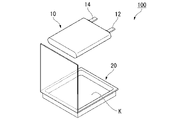
- FIG. 1 is a perspective view of the all-solid-state battery 100 according to the present embodiment.
- the all-solid-state battery 100 shown in FIG. 1 includes a power storage element 10 and an exterior body 20.
- the power storage element 10 is housed in the storage space K in the exterior body 20.
- FIG. 1 illustrates a state immediately before the power storage element 10 is housed in the exterior body 20 for easy understanding.
- the power storage element 10 has external terminals 12 and 14 that are electrically connected to the outside.
- the exterior body 20 has, for example, a metal foil 22 and a resin layer 24 laminated on both sides of the metal foil 22 (see FIG. 2).
- the exterior body 20 is a metal laminate film in which a metal foil 22 is coated with a polymer film (resin layer 24) from both sides.
- the metal foil 22 is, for example, an aluminum foil.
- the resin layer 24 is, for example, a polymer film such as polypropylene.
- the resin layer 24 may be the same or different on the inside and the outside.
- a polymer having a high melting point such as polyethylene terephthalate (PET) or polyamide (PA) is used as the outer resin layer, and polyethylene (PE), polypropylene (PP), or polyvinyl chloride (polyvinyl chloride) is used as the inner resin layer.
- PVC polyethylene tetrafluoride resin
- FEP ethylene fluoride propylene resin
- CFE ethylene trifluoride chloride resin
- PVF polyvinyl chloride
- a resin layer obtained by molding two or more types of resins into a matrix or a resin layer having a multi-layer structure of two or more layers is used. You may use it.
- the internal pressure of the accommodation space K surrounded by the exterior body 20 is less than 101.3 kPa.
- the internal pressure of the containment space K is less than atmospheric pressure.
- the internal pressure means the pressure inside the accommodation space K.
- the internal pressure of the exterior body 20 is lower than the external pressure applied to the exterior body 20.
- the external pressure applied to the exterior body 20 is, for example, atmospheric pressure.
- the difference between the external pressure and the internal pressure applied to the exterior body 20 is, for example, 30 kPa or more and 100 kPa or less, preferably 50 kPa or more and 100 kPa or less.
- the internal pressure of the exterior body 20 is, for example, 30 kPa lower than the external pressure, preferably 50 kPa lower than the external pressure, and 100 kPa lower than the external pressure.
- the adhesion between the positive electrode current collector 11A and the positive electrode active material layer 11B, or the negative electrode current collector 13A and the negative electrode active material 13B is improved. Further, the generation of a non-uniform current flow that bypasses the space is suppressed. As a result, the electrochemical reaction becomes uniform, and the cycle characteristics (maintenance rate) of the all-solid-state battery 100 are improved.
- the internal pressure inside the exterior body 20 can be measured by accommodating the all-solid-state battery 100 in the vacuum container and lowering the pressure inside the vacuum container. When the pressure inside the vacuum vessel drops by a certain value or more, the internal pressure of the exterior body 20 becomes larger than the external pressure, and the exterior body 20 begins to swell. The pressure when the exterior body 20 starts to swell is defined as the internal pressure inside the exterior body 20.
- the halogenated gas causes corrosion in the metal parts (positive electrode current collector 11A, negative electrode current collector 13A, etc., which will be described later) in the power storage element 10, and is one of the causes of lowering the current collection function. That is, by reducing the amount of gas and water existing in the exterior body 20 by creating a vacuum inside the exterior body 20, corrosion of the positive electrode current collector 11A or the negative electrode current collector 13A in the all-solid-state battery 100 is suppressed. The cycle characteristics (maintenance rate) of the all-solid-state battery 100 are improved.
- a solid electrolyte side reaction is a reaction that accompanies the decomposition of a solid electrolyte and uses some of the energy used for charging or discharging. Suppressing the side reactions of the solid electrolyte improves the electrochemical stability of the solid electrolyte. Further, a part of the energy used for charging or discharging is suppressed from being used for decomposing the solid electrolyte, and the cycle characteristics (maintenance rate) of the all-solid-state battery 100 is improved.
- the gas contained in the exterior body 20 is at least one selected from, for example, argon, nitrogen, oxygen, carbonic acid, neon, helium, and hydrogen. By controlling the gas contained in the exterior body 20, the generation of halogenated gas can be further suppressed.
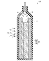
- FIG. 2 is a cross-sectional view of the all-solid-state battery 100 according to the present embodiment.
- the all-solid-state battery 100 has a positive electrode 11, a negative electrode 13, a solid electrolyte layer 15, external terminals 12, 14, and an accommodation space K.
- the positive electrode 11 has a positive electrode current collector 11A and a positive electrode active material layer 11B.
- the negative electrode 13 has a negative electrode current collector 13A and a negative electrode active material layer 13B.
- the solid electrolyte layer 15 is located between, for example, the positive electrode active material layer 11B and the negative electrode active material layer 13B.
- the all-solid-state battery 100 is charged or discharged by the transfer of electrons via the positive electrode current collector 11A and the negative electrode current collector 13A, and the transfer of lithium ions via the solid electrolyte layer 15.
- the all-solid-state battery 100 may be a laminated body in which a positive electrode 11, a negative electrode 13, and a solid electrolyte layer 15 are laminated, or a wound body thereof.
- the all-solid-state battery 100 is used, for example, as a laminated battery, a square battery, a cylindrical battery, a coin battery, a button battery, or the like.
- the amount of water contained in the power storage element 10 is preferably 0.01 mg / g or more and 1 mg / g or less, and more preferably 0.01 mg / g or more and 0.5 mg / g or less per unit mass.
- the amount of water per unit mass contained in the power storage element 10 is obtained by dividing the weight of the water contained in the power storage element 10 by the weight of the power storage element 10.
- the amount of water contained in the power storage element 10 can be measured by using, for example, the Karl Fischer method.
- the amount of water contained in the power storage element 10 is 0.01 mg / g or more and 1 mg / g or less per unit mass, the particles constituting the power storage element 10 flow during pressure molding, and cracks occur in the power storage element 10. Can be suppressed.
- the cycle characteristics (maintenance rate) of the all-solid-state battery 100 are improved. This is because the current and the flow of lithium ions that bypass the cracks are unlikely to occur, and the charging and discharging reactions can be suppressed from becoming locally non-uniform.
- the jig and the power storage element 10 may be in strong contact with each other during pressure molding. Therefore, cracks are likely to occur when the power storage element 10 is removed from the jig. As described above, cracks in the power storage element 10 can cause locally uneven charging and discharging reactions.
- the particles constituting the power storage element 10 become difficult to flow during pressure molding, and the particles adhere to each other become non-uniform, resulting in the power storage element 10. Cracks are likely to occur. As described above, the crack in the power storage element 10 causes a locally non-uniform charge / discharge reaction, and causes a decrease in the cycle characteristics (maintenance rate) of the all-solid-state battery 100.
- the amount of water in the accommodation space K is, for example, 1100 ppmv or less.
- the amount of water in the storage space K is preferably, for example, 0.5 ppmv or more and 600 ppmv or less.
- the halogenated gas is one of the causes of causing corrosion in the metal portion (current collector, conductive auxiliary agent, storage container, etc.) of the power storage element 10 and deteriorating the current collecting function.
- the generation of the halogenated gas is suppressed, it is possible to suppress the locally non-uniformity of the electrochemical reaction, and the cycle characteristics (maintenance rate) of the all-solid-state battery 100 are further improved.
- Solid electrolyte layer 15 contains a solid electrolyte.
- the solid electrolyte layer 15 contains, for example, a solid electrolyte represented by the following formula (1). Li 3 + a-e E 1-b G b D c X de ... (1)
- E is a trivalent or tetravalent element.
- E is, for example, at least one element selected from the group consisting of Al, Sc, Y, Zr, Hf and lanthanoids.
- Lanthanoids are La, Ce, Pr, Nd, Pm, Sm, Eu, Gd, Tb, Dy, Ho, Er, Tm, Yb, Lu.
- E preferably contains Sc or Zr, and is particularly preferably Zr.
- E contains Sc or Zr, the ionic conductivity of the solid electrolyte is increased.
- G is an element contained as necessary.
- G is Na, K, Rb, Cs, Mg, Ca, Sr, Ba, B, Si, Al, Ti, Cu, Sc, Y, Zr, Nb, Ag, In, Sn, Sb, Hf, Ta, W. , Au, and Bi, at least one element selected from the group.
- the solid electrolyte contains an element of G, the amount of lithium ions, which are carrier ions, increases or decreases, and the ionic conductivity increases.
- G in the formula (1) may be a monovalent element selected from Na, K, Rb, Cs, and Ag among the above.
- G When G is a monovalent element, it becomes a solid electrolyte having high ionic conductivity and a wide potential window on the reduction side.
- G is particularly preferably Na and / or Cs.
- G in the formula (1) may be a divalent element selected from Mg, Ca, Ba, Sr, Cu, and Sn among the above.
- G is a divalent element, carrier ions increase, resulting in a solid electrolyte having high ionic conductivity and a wide potential window on the reduction side.
- G is particularly preferably Mg and / or Ca.
- G in the formula (1) may be a trivalent selected from Al, Y, In, Au, and Bi among the above.
- G is a trivalent element, carrier ions increase and the solid electrolyte has high ionic conductivity.
- G is particularly preferably any one selected from the group consisting of In, Au and Bi.
- G in the formula (1) may be Zr, Hf, Sn, which are tetravalent elements among the above. When G is a tetravalent element, it becomes a solid electrolyte having high ionic conductivity. G preferably contains Hf and / or Zr in particular.
- G in the formula (1) may be a pentavalent element selected from Nb, Sb, and Ta among the above.
- G is a pentavalent element, holes are formed and carrier ions easily move, so that the solid electrolyte has high ionic conductivity.
- G preferably contains Sb and / or Ta in particular.
- G in the formula (1) may be W, which is a hexavalent element among the above.
- G When G is a hexavalent element, it becomes a solid electrolyte having high ionic conductivity.
- D in the formula (1) is contained as needed.
- D is at least one selected from the group consisting of CO 3 , SO 4 , BO 3 , PO 4 , NO 3 , SiO 3 , OH, and O 2 .
- the potential window on the reduction side of the solid electrolyte becomes wide.
- D is preferably at least one selected from the group consisting of SO 4 , CO 3 , PO 4 , and O 2 , and is particularly preferably SO 4 .
- the covalent bond between D and E is strong, the ionic bond between E and X is also strong. Therefore, it is presumed that E in the compound is difficult to be reduced and the compound has a wide potential window on the reduction side.
- X in the formula (1) is an essential element.
- X is at least one selected from the group consisting of F, Cl, Br, and I.
- X has a large ionic radius per valence.
- the conductivity of lithium ions in the solid electrolyte is increased.
- X preferably contains Cl.
- F In order to improve the balance between the oxidation resistance and the reduction resistance of the solid electrolyte, it is preferable that X contains F.
- X preferably contains I.
- a 0.
- a the above-mentioned numerical value determined according to the valence of G.
- b is 0 or more and less than 0.5.
- the solid electrolyte represented by the formula (1) contains E as an essential element, but does not have to contain G.
- b is 0.1 or more, the effect obtained by containing G in the solid electrolyte can be sufficiently obtained.
- b is preferably less than 0.5 from the viewpoint of suppressing a decrease in ionic conductivity of the solid electrolyte.
- b is more preferably 0.45 or less.
- c is 0 or more and 5 or less. Therefore, D does not have to be contained in the solid electrolyte.
- c is preferably 0.1 or more.
- c is 0.1 or more, the effect of widening the potential window on the reduction side of the solid electrolyte due to the inclusion of D can be sufficiently obtained. If the content of D is too large, there is a concern that the ionic conductivity of the solid electrolyte may decrease due to the narrowing of the space for carrier ions to move, and from the viewpoint of suppressing this, c is 5 or less, 2.5. The following is preferable.
- d is greater than 0 and less than or equal to 7.1.
- d is 7.1 or less, the binding force to carrier ions due to the excessive content of X can be suppressed, and the decrease in ionic conductivity of the solid electrolyte can be suppressed, which is preferable.
- e is 0 or more and 2 or less. Further, 0 ⁇ de.
- the formula (1) satisfies 0 ⁇ e ⁇ 2, 0 ⁇ de, the Li content and the X content contained in the compound represented by the formula (1) become appropriate, and the ionic conductivity of the solid electrolyte becomes appropriate. Increase.
- the solid electrolyte represented by the formula (1) is preferably E in Zr and X in Cl.
- the compound represented by the formula (1) is preferably Li 2 ZrCl 6 , Li 2 ZrCl 4 SO 4 , or Li 2 ZrOCl 4 as a solid electrolyte having a good balance between ionic conductivity and a potential window. ..
- the solid electrolyte layer 15 may contain other substances together with the solid electrolyte represented by the formula (1).
- Other substances are, for example, Li 2 O, Li 2 CO 3 , LiX (X is at least one selected from the group consisting of F, Cl, Br, I), Sc 2 O 3 , Sc 2 O 3, Sc X 3 .
- (X is at least one element selected from the group consisting of F, Cl, Br, I.)
- the ionic conductivity of the solid electrolyte layer 15 increases.
- the above-mentioned other substances have a function of assisting ionic connection between particles composed of the solid electrolyte represented by the formula (1). It is presumed that this reduces the grain boundary resistance between the particles of the solid electrolyte represented by the formula (1) and increases the ionic conductivity of the solid electrolyte layer 15 as a whole.
- the content of other substances in the solid electrolyte layer 15 is, for example, 0.1% by mass or more and 1.0% by mass or less from the viewpoint of obtaining the effect of reducing the intergranular resistance between particles. On the other hand, if the content of the other substance is more than 1.0% by mass, the solid electrolyte layer 15 is likely to be cracked, and the ionic connection between the particles is hindered.
- the solid electrolyte layer 15 may contain a binder.
- the solid electrolyte layer 15 is, for example, a fluororesin such as polyvinylidene fluoride (PVDF) or polytetrafluoroethylene (PTFE), or an imide-based resin such as cellulose, styrene / butadiene rubber, ethylene / propylene rubber, polyimide resin, or polyamideimide resin. It may contain a resin, an ion conductive polymer and the like.
- PVDF polyvinylidene fluoride
- PTFE polytetrafluoroethylene
- imide-based resin such as cellulose, styrene / butadiene rubber, ethylene / propylene rubber, polyimide resin, or polyamideimide resin. It may contain a resin, an ion conductive polymer and the like.
- the ionic conductive polymer is, for example, a monomer of a polymer compound (polyether-based polymer compound such as polyethylene oxide or polypropylene oxide, polyphosphazene, etc.) and a lithium salt such as LiCl 4 , LiBF 4 , LiPF 6 , LiTFSI, etc. Alternatively, it is a compound obtained by combining an alkali metal salt mainly composed of lithium.
- the content of the binder is preferably 0.1% by volume or more and 30% by volume or less of the entire solid electrolyte layer 15. The binder helps maintain good bonding between the solid electrolytes of the solid electrolyte layer 15, prevents the occurrence of cracks between the solid electrolytes, and suppresses a decrease in ionic conductivity and an increase in grain boundary resistance. ..
- the positive electrode 11 has, for example, a positive electrode current collector 11A and a positive electrode active material layer 11B containing a positive electrode active material.
- the positive electrode current collector 11A preferably has high conductivity.
- metals such as silver, palladium, gold, platinum, aluminum, copper, nickel, titanium and stainless steel and alloys thereof, or conductive resins can be used.
- the positive electrode current collector 11A may be in the form of powder, foil, punching, or expand. From the viewpoint of not deteriorating the current collecting function of the positive electrode current collector 11A, dehydration is performed by heating and vacuum drying in a glove box in which argon gas is circulated, and then using a glass bottle, an aluminum laminate bag, or the like, the positive electrode current collector 11A is used. It is preferable to store.
- the dew point in the glove box is, for example, ⁇ 30 ° C. or lower and ⁇ 90 ° C. or higher.
- the positive electrode active material layer 11B is formed on one side or both sides of the positive electrode current collector 11A.
- the positive electrode active material layer 11B contains a positive electrode active material.
- the positive electrode active material layer 11B may contain, for example, the solid electrolyte represented by the above formula (1). Further, the positive electrode active material layer 11B may contain a conductive auxiliary agent and a binder.
- the positive electrode mixture used for the positive electrode active material layer 11B is produced by mixing, for example, in a glove box in which argon gas is circulated, using an agate mortar, a pot mill, a blender, a hybrid mixer, or the like. From the viewpoint of satisfactorily press-molding the power storage element 10, the dew point in the glove box is preferably ⁇ 30 ° C. or lower and ⁇ 90 ° C. or higher.
- the oxygen concentration in the glove box is, for example, 1 ppm or less.
- the positive electrode active material contained in the positive electrode active material layer 11B is, for example, a lithium-containing transition metal oxide, a transition metal fluoride, a polyanion, a transition metal sulfide, a transition metal oxyfluoride, a transition metal oxysulfide, or a transition metal oxynitride. Is.
- the positive electrode active material is not particularly limited as a positive electrode active material as long as it can reversibly proceed with the release and storage of lithium ions and the desorption and insertion of lithium ions, and is used in known lithium ion secondary batteries.
- the positive electrode active material that has been used can be used.
- the positive electrode active material is, for example, lithium cobaltate (LiCoO 2 ), lithium nickelate (LiNiO 2 ), lithium manganese spinel (LiMn 2 O 4 ), and general formula: LiNi x Coy Mn z Ma O 2 ( x + y + z + a).
- M is one or more elements selected from Al, Mg, Nb, Ti, Cu, Zn, Cr. ), Lithium vanadium compound (LiV 2 O 5 , Li 3 V 2 (PO 4 ) 3 , LiVOPO 4), olivine type LiMPO 4 (where M is Co, Ni, Mn, Fe, Indicates one or more elements selected from Mg, V, Nb, Ti, Al, and Zr), lithium titanate (Li 4 Ti 5 O 12 ), LiNi x Coy Al z O 2 (0.9 ⁇ x + y + z ⁇ 1.1) and other composite metal oxides.
- the positive electrode active material used for the positive electrode active material layer 11B is dehydrated by heating and vacuum drying in a glove box in which argon gas is circulated from the viewpoint of good pressure molding, and then a glass bottle or an aluminum laminated bag is used. It is preferable to store it.
- the dew point in the glove box is preferably ⁇ 30 ° C. or lower and ⁇ 90 ° C. or higher.
- a positive electrode active material containing no lithium can be used by starting the battery from discharging.
- positive electrode active materials include lithium-free metal oxides (MnO 2 , V 2 O 5 , etc.), lithium-free metal sulfides (MoS 2 , etc.), lithium-free fluorides (FeF 3 , VF 3 , etc.). ) And so on.
- the negative electrode 13 has, for example, a negative electrode current collector 13A and a negative electrode active material layer 13B containing a negative electrode active material.
- the negative electrode current collector 13A preferably has high conductivity. For example, it is preferable to use metals such as silver, palladium, gold, platinum, aluminum, copper, nickel, stainless steel and iron and alloys thereof, or conductive resins.
- the negative electrode current collector 13A may be in the form of powder, foil, punching, or expand. Further, from the viewpoint of not deteriorating the current collecting function of the negative electrode current collector 13A, dehydration is performed by heating and vacuum drying in a glove box in which argon gas is circulated, and then a glass bottle or an aluminum laminated bag is used to perform dehydration of the negative electrode current collector. It is preferable to store 13A.
- the dew point in the glove box is, for example, ⁇ 30 ° C. or lower and ⁇ 90 ° C. or higher.
- the negative electrode active material layer 13B is formed on one side or both sides of the negative electrode current collector 13A.
- the negative electrode active material layer 13B contains a negative electrode active material.
- the negative electrode active material layer 13B may contain, for example, the solid electrolyte represented by the above formula (1). Further, the negative electrode active material layer 13B may contain a conductive auxiliary agent and a binder.
- the negative electrode mixture used for the negative electrode active material layer 13B is produced by mixing, for example, in a glove box in which argon gas is circulated, using an agate mortar, a pot mill, a blender, a hybrid mixer, or the like. From the viewpoint of performing pressure molding of the power storage element 10, the dew point in the glove box is preferably ⁇ 30 ° C. or lower and ⁇ 90 ° C. or higher.
- the oxygen concentration in the glove box is, for example, 1 ppm or less.
- the negative electrode active material contained in the negative electrode active material layer 13B may be any compound capable of storing and releasing movable ions, and a known negative electrode active material used in a lithium ion secondary battery can be used.
- Negative negative active materials include, for example, alkali metal simple substances, alkali metal alloys, graphite (natural graphite, artificial graphite), carbon nanotubes, non-graphitizable carbon, easily graphitized carbon, carbon materials such as low-temperature calcined carbon, aluminum, silicon, etc.
- the negative electrode active material used for the negative electrode active material layer 13B is dehydrated by heating and vacuum drying in a glove box in which argon gas is circulated from the viewpoint of good pressure molding, and then using a glass bottle, an aluminum laminate bag, or the like. Good to keep.
- the dew point in the glove box is preferably ⁇ 30 ° C. or lower and ⁇ 90 ° C. or higher.
- the conductive auxiliary agent is not particularly limited as long as it improves the electron conductivity of the positive electrode active material layer 11B and the negative electrode active material layer 13B, and known conductive auxiliary agents can be used.
- Conductive auxiliaries include, for example, carbon-based materials such as graphite, carbon black, graphene, and carbon nanotubes, metals such as gold, platinum, silver, palladium, aluminum, copper, nickel, stainless steel, and iron, and conductive oxidation of ITO. Things, or mixtures thereof, may be mentioned.
- the conductive auxiliary agent may be in the form of powder or fiber.
- the conductive auxiliary agent it is advisable to perform dehydration by heating and vacuum drying in a glove box in which argon gas is circulated, and then store the conductive auxiliary agent in a glass bottle or an aluminum laminate bag. ..
- the dew point in the glove box is preferably ⁇ 30 ° C. or lower and ⁇ 90 ° C. or higher.
- the binders are the positive electrode current collector 11A and the positive electrode active material layer 11B, the negative electrode current collector 13A and the negative electrode active material layer 13B, the positive electrode active material layer 11B, the negative electrode active material layer 13B and the solid electrolyte layer 15, and the positive electrode active material.
- Various materials constituting the layer 11B and various materials constituting the negative electrode active material layer 13B are joined.
- the binder is preferably used within a range that does not lose the functions of the positive electrode active material layer 11B and the negative electrode active material layer 13B.
- the binder may be any as long as it can be bonded as described above, and examples thereof include fluororesins such as polyvinylidene fluoride (PVDF) and polytetrafluoroethylene (PTFE).
- PVDF polyvinylidene fluoride
- PTFE polytetrafluoroethylene
- the binder for example, cellulose, styrene / butadiene rubber, ethylene / propylene rubber, polyimide resin, polyamide-imide resin and the like may be used.
- a conductive polymer having electron conductivity or an ion conductive polymer having ion conductivity may be used as the binder.
- the conductive polymer having electron conductivity examples include polyacetylene and the like. In this case, since the binder also exerts the function of the conductive auxiliary agent particles, it is not necessary to add the conductive auxiliary agent.
- the ionic conductive polymer having ionic conductivity for example, one that conducts lithium ions or the like can be used, and polymer compounds (polyether-based polymer compounds such as polyethylene oxide and polypropylene oxide, polyphosphazene) can be used. Etc.), and a composite of a lithium salt such as LiClO 4 , LiBF 4 , LiPF 6, LiTFSI, LiFSI, or an alkali metal salt mainly composed of lithium can be mentioned.
- Examples of the polymerization initiator used for the complexing include a photopolymerization initiator or a thermal polymerization initiator compatible with the above-mentioned monomers.
- the properties required for the binder include oxidation / reduction resistance and good adhesiveness.
- the content of the binder in the positive electrode active material layer 11B is not particularly limited, but 0.5 to 30% by volume of the positive electrode active material layer is preferable from the viewpoint of reducing the resistance of the positive electrode active material layer 11B. Further, from the viewpoint of improving the energy density, the content of the binder in the positive electrode active material layer 11B is preferably 0% by volume.
- the content of the binder in the negative electrode active material layer 13B is not particularly limited, but 0.5 to 30% by volume of the negative electrode active material layer is preferable from the viewpoint of reducing the resistance of the negative electrode active material layer 13B. Further, from the viewpoint of improving the energy density, the content of the binder in the negative electrode active material layer 13B is preferably 0% by volume.
- At least one of the positive electrode active material layer 11B, the negative electrode active material layer 13B, and the solid electrolyte layer 15 is provided with a non-aqueous electrolyte solution, an ionic liquid, and a gel electrolyte for the purpose of improving the rate characteristic, which is one of the battery characteristics. It may be mixed.
- the solid electrolyte is obtained by mixing and reacting the raw material powders at a predetermined molar ratio so as to obtain the desired composition.
- the reaction method is not limited, but a mechanochemical milling method, a sintering method, a melting method, a liquid phase method, a solid phase method, or the like can be used.
- the solid electrolyte can be produced by, for example, the mechanochemical milling method.
- a planetary ball mill device is prepared.
- a planetary ball mill device is a device that puts media (hard balls for promoting crushing or mechanochemical reaction) and materials into a special container, rotates and revolves, crushes the materials, or causes a mechanochemical reaction between materials. be.
- the solid electrolyte is produced, for example, in a glove box in which argon gas is circulated.
- the dew point in the glove box is, for example, ⁇ 20 ° C. or lower and ⁇ 90 ° C. or higher, preferably ⁇ 30 ° C. or lower and ⁇ 80 ° C. or higher.
- the oxygen concentration in the glove box is, for example, 1 ppm or less.
- a predetermined raw material is prepared in a container made of zirconia at a predetermined molar ratio so as to have a desired composition, and the container is sealed with a lid made of zirconia.
- a predetermined amount of zirconia balls are prepared in a zirconia container.
- the raw material may be powder or liquid.
- titanium chloride (TiCl 4 ) and tin chloride (SnCl 4 ) are liquids at room temperature.
- a mechanochemical reaction is caused by performing mechanochemical milling at a predetermined rotation speed and revolution speed for a predetermined time. By this method, a powdery solid electrolyte composed of a compound having a desired composition can be obtained.
- the all-solid-state battery according to this embodiment is manufactured by using, for example, a powder molding method.
- the powder molding method is also produced in the glove box.
- the dew point in the glove box is preferably ⁇ 20 ° C. or lower and ⁇ 90 ° C. or higher, for example.
- the oxygen concentration in the glove box is, for example, 1 ppm or less.
- a resin holder having a through hole in the center, a lower punch, and an upper punch are prepared.
- a metal holder made of die steel may be used instead of the resin holder in order to improve the moldability.
- the diameter of the through hole of the resin holder is, for example, 10 mm, and the diameter of the lower punch and the upper punch is, for example, 9.99 mm.
- the lower punch is inserted from under the through hole of the resin holder, and the powdered solid electrolyte is charged from the opening side of the resin holder.
- the upper punch is inserted on the powdered solid electrolyte charged, placed on a press machine, and pressed.
- the press pressure is, for example, 373 MPa.
- the powdered solid electrolyte is pressed by the upper punch and the lower punch in the resin holder to form the solid electrolyte layer 15.
- the upper punch is temporarily removed, and the material of the positive electrode active material layer is put into the upper punch side of the solid electrolyte layer 15. After that, the upper punch is inserted again and pressed.
- the press pressure is, for example, 373 MPa.
- the material of the positive electrode active material layer becomes the positive electrode active material layer 11B by pressing.
- the lower punch is temporarily removed, and the material of the negative electrode active material layer is put into the lower punch side of the solid electrolyte layer 15.
- the sample is turned upside down and the material of the negative electrode active material layer is charged onto the solid electrolyte layer 15 so as to face the positive electrode active material layer 11B.
- the lower punch is inserted again and pressed.
- the press pressure is, for example, 373 MPa.
- the material of the negative electrode active material layer becomes the negative electrode active material layer 13B by pressing.
- the upper punch is removed once, and the positive electrode current collector 11A and the upper punch are inserted in this order on the positive electrode active material layer 11B.
- the lower punch is removed once, and the negative electrode current collector 13A and the lower punch are inserted in this order on the negative electrode active material layer 13B.
- the positive electrode current collector 11A and the negative electrode current collector 13A are, for example, aluminum foil or copper foil having a diameter of 10 mm.
- the power storage element 10 is a stainless steel disk and a bakelite disk having four screw holes as needed, and is a stainless steel disk / bakelite disk / upper punch / power storage element 10 / lower punch / bakelite.
- the discs may be loaded in the order of discs made of stainless steel / discs made of stainless steel, and the screws may be tightened at four places.
- the upper punch and the positive electrode current collector 11A, the positive electrode current collector 11A and the positive electrode active material 11B, the lower punch and the negative electrode current collector 13A, and the negative electrode current collector 13A and the negative electrode active material 13B respectively. Improves bondability.
- the power storage element 10 may have a similar mechanism having a shape-retaining function.
- the exterior body 20 improves the weather resistance of the all-solid-state battery 100.
- the remaining opening is heat-sealed.
- the internal pressure in the accommodation space K of the exterior body 20 is set to less than 101.3 kPa, and the opening of the exterior body 20 is sealed while maintaining this state.
- a space is formed between the positive electrode current collector 11A and the positive electrode active material layer 11B, or between the negative electrode current collector 13A and the negative electrode active material 13B. It can be sealed in a state where it is suppressed. Further, the exterior body 20 can be sealed in a state where the amount of gas and water existing in the accommodation space K is small.
- the method for manufacturing the power storage element 10 described above has been described by taking the powder molding method as an example, but it may be manufactured by a sheet molding method containing a resin.
- the sheet molding method is also produced in the glove box.
- the glove box is preferably performed in an environment where the dew point is ⁇ 20 ° C. or lower and ⁇ 90 ° C. or higher.
- a solid electrolyte paste containing a powdered solid electrolyte is prepared.
- the solid electrolyte layer 15 is prepared by applying the prepared solid electrolyte paste to a PET film, a fluororesin film, or the like, drying, temporary molding, and peeling.
- the positive electrode 11 is produced by applying a positive electrode active material paste containing a positive electrode active material on the positive electrode current collector 11A, drying and temporarily molding the positive electrode active material layer 11B.
- the negative electrode 13 is manufactured by applying a paste containing the negative electrode active material on the negative electrode current collector 13A, drying and temporarily molding the negative electrode current collector 13A to form the negative electrode active material layer 13B.
- the positive electrode 11, the negative electrode 13, and the solid electrolyte layer 15 can be punched into a required size and shape.
- the solid electrolyte layer 15 is sandwiched between the positive electrode 11 and the negative electrode 13 so that the positive electrode active material layer 11B and the negative electrode active material layer 13B face each other, and the whole is pressurized and adhered.
- the power storage element 10 of the present embodiment is obtained.
- the positive electrode current collector 11A or the negative electrode current collector 13AA is collected by corrosion due to halogenated gas. Since the deterioration of the electric function is suppressed and a uniform electrochemical reaction is possible, the cycle characteristics (maintenance rate) of the all-solid-state battery 100 are improved.
- Example 1 Synthesis of solid electrolyte- Dew point of circulating argon gas-90 ° C, oxygen concentration 1 ppm, synthesis of solid electrolyte in a glove box in atmospheric pressure environment, mixing of positive electrode active material layer material, mixing of negative electrode active material layer material, and all-solid-state battery It was made.
- Li 2 SO 4 and ZrCl 4 were weighed as raw material powders so as to have a molar ratio of 1: 1.
- the weighed raw material powder was placed in a Zr container together with a Zr ball having a diameter of 5 mm, and a mechanochemical milling treatment was performed using a planetary ball mill.
- the treatment was carried out under the condition of a rotation speed of 500 rpm, mixed for 50 hours, and then sieved to a 200 ⁇ m mesh. As a result, a powder of Li 2 ZrSO 4 Cl 4 was obtained as a solid electrolyte.
- a power storage element composed of a positive electrode current collector / positive electrode mixture layer / electrolyte layer / negative electrode mixture layer / negative electrode current collector was produced by a powder molding method. ..
- the power storage element was manufactured in a glove box having a dew point of ⁇ 90 ° C. and an oxygen concentration of 1 ppm in which argon gas was circulated.
- a resin holder having a through hole with a diameter of 10 mm in the center, a lower punch with a diameter of 9.99 mm made of SKD11 material, and an upper punch were prepared.
- a lower punch was inserted from under the through hole of the resin holder, and 110 mg of solid electrolyte was charged from the opening side of the resin holder.
- the upper punch was then inserted over the solid electrolyte.
- This first unit was placed on a press machine and pressed at a pressure of 373 MPa to form a solid electrolyte layer. The first unit was taken out of the press and the upper punch was removed.
- the upper punch was removed once, and the positive electrode current collector (aluminum foil, diameter 10 mm, thickness 20 um) and the upper punch were inserted in this order on the positive electrode active material layer.
- the lower punch was once removed, and the negative electrode current collector (copper foil, diameter 10 mm, thickness 10 um) and the lower punch were inserted in this order on the negative electrode active material layer to obtain a fourth unit.
- a power storage element composed of a positive electrode current collector, a positive electrode active material layer, a solid electrolyte layer, a negative electrode active material layer, and a negative electrode current collector was produced.
- a stainless steel disk with a diameter of 50 mm and a thickness of 5 mm and a Bakelite disk having screw holes at four locations were prepared, and the battery elements were set as follows.
- the stainless steel disk / bakelite disk / 4th unit / bakelite disk / stainless steel disk were loaded in this order, and the 5th unit was manufactured by tightening the screws at 4 places. Screws for connecting external terminals were inserted into the screw holes on the sides of the upper punch and lower punch.
- the obtained power storage element was housed in the exterior body.
- the storage element was housed in a dry room with a dew point of ⁇ 50 ° C.
- An A4 size aluminum laminated bag was prepared as an exterior body to enclose the 5th unit.
- Aluminum foil width 4 mm, length 40 mm, thickness 100 ⁇ m
- nickel foil width 4 mm, length
- PP polypropylene
- 40 mm thick and 100 ⁇ m thick were heat-bonded at intervals so as not to cause a short circuit.
- the inside of the exterior body was evacuated to a degree of vacuum of -50 kPa (atmospheric pressure was converted to 0 kPa), and the opening was heat-sealed to form an all-solid-state battery.
- the internal pressure inside the exterior body was 51.3 kPa.
- the difference between the external pressure and the internal pressure was 50 kPa.
- the positive electrode current collector and the negative electrode current collector are taken out, and the surface of the surface in contact with the positive electrode active material layer or the negative electrode active material layer using an optical microscope (objective lens 50 times). The area of the portion having a different contrast from the unused positive electrode current collector or the negative electrode current collector was determined. It is assumed that the contrast change is accompanied by cracks.
- a charge / discharge test was conducted on the manufactured all-solid-state battery.
- the charge / discharge test was performed in a constant temperature bath at 25 ° C. Charging was performed at 0.05 C and up to 2.8 V at a constant current and constant voltage (referred to as CCCV). Charging was completed until the current became 1 / 40C. The discharge was a constant current discharge at 0.05 C to 1.3 V. Charging and discharging were performed for 50 cycles under the above conditions, and the maintenance rate after 50 cycles was calculated from the following formula (2).
- Example 1 The results of Example 1 are summarized in Tables 1 to 5 described later.
- Example 2 to 10 differ from Example 1 in that the degree of vacuum inside the exterior body is changed. Other conditions were the same as in Example 1, and the positive electrode current collector, the negative electrode current collector were observed for discoloration, and the maintenance rate of the all-solid-state battery was measured. The results of Examples 2 to 10 are summarized in Table 1 below.
- Comparative Example 1 is different from Example 1 in that the inside of the exterior body was not evacuated when the opening of the exterior body was heat-sealed.
- the internal pressure was 101.3 kPa.
- the difference between the external pressure and the internal pressure was 0 kPa.
- discoloration observation of the positive electrode current collector and the negative electrode current collector and the maintenance rate of the all-solid-state battery were measured in the same manner as in Example 1.
- the results of Comparative Example 1 are summarized in Table 1 below.
- Example 11 In Example 11, the composition of the solid electrolyte was changed.
- LiCl and ZrCl 4 were weighed as raw material powders so as to have a molar ratio of 2: 1 and a solid electrolyte Li 2 ZrCl 6 synthesized by mechanochemical milling treatment was used. Different from. As for other conditions, discoloration observation of the positive electrode current collector and the negative electrode current collector, and the maintenance rate of the all-solid-state battery were measured in the same manner as in Example 1. The results of Example 11 are summarized in Table 1 below.
- Examples 12 to 20 differ from Example 11 in that the degree of vacuum inside the exterior body is changed. Other conditions were the same as in Example 11, and the positive electrode current collector, the negative electrode current collector were observed for discoloration, and the maintenance rate of the all-solid-state battery was measured. The results of Examples 12 to 20 are summarized in Table 1 below.
- Comparative Example 2 is different from Example 11 in that the inside of the exterior body was not evacuated when the opening of the exterior body was heat-sealed.
- the internal pressure was 101.3 kPa.
- the difference between the external pressure and the internal pressure was 0 kPa.
- Other conditions were the observation of discoloration of the positive electrode current collector and the negative electrode current collector, and the retention rate of the all-solid-state battery was measured in the same manner as in Example 11.
- the results of Comparative Example 2 are summarized in Table 1 below.
- Example 21 In Example 21, the composition of the solid electrolyte was changed. In Example 21, Li 2 O and ZrCl 4 were weighed as raw material powders so as to have a molar ratio of 1: 1 and a solid electrolyte Li 2 ZrOCl 4 synthesized by mechanochemical milling treatment was used. Different from Example 1. As for other conditions, discoloration observation of the positive electrode current collector and the negative electrode current collector, and the maintenance rate of the all-solid-state battery were measured in the same manner as in Example 1. The results of Example 21 are summarized in Table 2 below.
- Examples 22 to 30 differ from Example 21 in that the degree of vacuum inside the exterior body is changed. Other conditions were the same as in Example 21, and the positive electrode current collector, the negative electrode current collector were observed for discoloration, and the maintenance rate of the all-solid-state battery was measured. The results of Examples 22 to 30 are summarized in Table 2 below.
- Comparative Example 3 is different from Example 21 in that the inside of the exterior body was not evacuated when the opening of the exterior body was heat-sealed.
- the internal pressure was 101.3 kPa.
- the difference between the external pressure and the internal pressure was 0 kPa.
- Other conditions were the observation of discoloration of the positive electrode current collector and the negative electrode current collector, and the retention rate of the all-solid-state battery was measured in the same manner as in Example 21.
- the results of Comparative Example 3 are summarized in Table 2 below.
- Example 31 In Example 31, the composition of the solid electrolyte was changed.
- Li 3 PO 4 and ZrCl 4 as raw material powders were weighed so as to have a molar ratio of 1: 3, and a solid electrolyte LiZr (PO 4 ) 0.33 Cl synthesized by mechanochemical milling treatment. The point that 4 was used is different from Example 1.
- discoloration observation of the positive electrode current collector and the negative electrode current collector, and the maintenance rate of the all-solid-state battery were measured in the same manner as in Example 1.
- the results of Example 31 are summarized in Table 2 below.
- Examples 32 to 40 differ from Example 31 in that the degree of vacuum inside the exterior body is changed. Other conditions were the same as in Example 31, and the discoloration observation of the positive electrode current collector and the negative electrode current collector and the maintenance rate of the all-solid-state battery were measured. The results of Examples 32 to 40 are summarized in Table 2 below.
- Comparative Example 4 is different from Example 31 in that the inside of the exterior body was not evacuated when the opening of the exterior body was heat-sealed.
- the internal pressure was 101.3 kPa.
- the difference between the external pressure and the internal pressure was 0 kPa.
- Other conditions were the observation of discoloration of the positive electrode current collector and the negative electrode current collector, and the retention rate of the all-solid-state battery was measured in the same manner as in Example 31.
- the results of Comparative Example 4 are summarized in Table 2 below.
- Example 41 In Example 41, the composition of the solid electrolyte was changed.
- Li 3 PO 4 and Y Cl 3 as raw material powders were weighed so as to have a molar ratio of 1: 3, and a solid electrolyte LiY (PO 4 ) 0.33 Cl synthesized by mechanochemical milling treatment. The point that 3 was used is different from Example 1.
- discoloration observation of the positive electrode current collector and the negative electrode current collector, and the maintenance rate of the all-solid-state battery were measured in the same manner as in Example 1.
- the results of Example 41 are summarized in Table 3 below.
- Examples 42 to 50 are different from Examples 41 in that the degree of vacuum inside the exterior body is changed. Other conditions were the same as in Example 41, and the discoloration observation of the positive electrode current collector and the negative electrode current collector and the maintenance rate of the all-solid-state battery were measured. The results of Examples 42 to 50 are summarized in Table 3 below.
- Comparative Example 5 is different from Example 41 in that the inside of the exterior body was not evacuated when the opening of the exterior body was heat-sealed.
- the internal pressure was 101.3 kPa.
- the difference between the external pressure and the internal pressure was 0 kPa.
- Other conditions were the observation of discoloration of the positive electrode current collector and the negative electrode current collector, and the retention rate of the all-solid-state battery was measured in the same manner as in Example 41.
- the results of Comparative Example 5 are summarized in Table 3 below.
- Example 51 In Example 51, the composition of the solid electrolyte was changed.
- Li 3 PO 4 , ZrCl 4 and AlCl 3 were weighed as raw material powders so as to have a molar ratio of 4.3: 7: 3, and the solid electrolyte Li 1 was synthesized by mechanochemical milling treatment. .3 Al 0.3 Zr 0.7 (PO 4 ) 0.43 Cl 3.7 is used, which is different from Example 1.
- discoloration observation of the positive electrode current collector and the negative electrode current collector, and the maintenance rate of the all-solid-state battery were measured in the same manner as in Example 1.
- the results of Example 51 are summarized in Table 3 below.
- Examples 52 to 60 are different from Examples 51 in that the degree of vacuum inside the exterior body is changed. Other conditions were the same as in Example 51, and the discoloration observation of the positive electrode current collector and the negative electrode current collector and the maintenance rate of the all-solid-state battery were measured. The results of Examples 52 to 60 are summarized in Table 3 below.
- Comparative Example 6 is different from Example 51 in that the inside of the exterior body was not evacuated when the opening of the exterior body was heat-sealed.
- the internal pressure was 101.3 kPa.
- the difference between the external pressure and the internal pressure was 0 kPa.
- Other conditions were the observation of discoloration of the positive electrode current collector and the negative electrode current collector, and the retention rate of the all-solid-state battery was measured in the same manner as in Example 51.
- the results of Comparative Example 6 are summarized in Table 3 below.
- Example 61 In Example 61, the composition of the solid electrolyte was changed. In Example 61, Li 2 SO 4 and ZrCl 4 as raw material powders were weighed so as to have a molar ratio of 0.9: 1, and a solid electrolyte Li 1.8 Zr (SO) synthesized by mechanochemical milling treatment was performed. 4 ) The point that 0.9 Cl 4 was used is different from Example 1. As for other conditions, discoloration observation of the positive electrode current collector and the negative electrode current collector, and the maintenance rate of the all-solid-state battery were measured in the same manner as in Example 1. The results of Example 61 are summarized in Table 4 below.
- Examples 62 to 70 are different from Examples 61 in that the degree of vacuum inside the exterior body is changed. Other conditions were the same as in Example 61, and the discoloration observation of the positive electrode current collector and the negative electrode current collector and the maintenance rate of the all-solid-state battery were measured. The results of Examples 62 to 70 are summarized in Table 4 below.
- Comparative Example 7 is different from Example 61 in that the inside of the exterior body was not evacuated when the opening of the exterior body was heat-sealed. The internal pressure was 101.3 kPa. The difference between the external pressure and the internal pressure was 0 kPa. Other conditions were the observation of discoloration of the positive electrode current collector and the negative electrode current collector, and the retention rate of the all-solid-state battery was measured in the same manner as in Example 61. The results of Comparative Example 7 are summarized in Table 4 below.
- Example 71 In Example 71, the composition of the solid electrolyte was changed. In Example 71, Li 2 SO 4 and ZrCl 4 as raw material powders were weighed so as to have a molar ratio of 1.1: 1, and a solid electrolyte Li 2.2 Zr (SO) synthesized by mechanochemical milling treatment was performed. 4 ) 1.1 The point that Cl 4 is used is different from Example 1. As for other conditions, discoloration observation of the positive electrode current collector and the negative electrode current collector, and the maintenance rate of the all-solid-state battery were measured in the same manner as in Example 1. The results of Example 71 are summarized in Table 4 below.
- Examples 72 to 80 are different from Examples 71 in that the degree of vacuum inside the exterior body is changed. Other conditions were the same as in Example 71, and the discoloration observation of the positive electrode current collector and the negative electrode current collector and the maintenance rate of the all-solid-state battery were measured. The results of Examples 72-80 are summarized in Table 4 below.
- Comparative Example 8 is different from Example 71 in that the inside of the exterior body was not evacuated when the opening of the exterior body was heat-sealed. The internal pressure was 101.3 kPa. The difference between the external pressure and the internal pressure was 0 kPa. Other conditions were the observation of discoloration of the positive electrode current collector and the negative electrode current collector, and the retention rate of the all-solid-state battery was measured in the same manner as in Example 71. The results of Comparative Example 8 are summarized in Table 4 below.
- Example 81 In Example 81, the composition of the solid electrolyte was changed. In Example 81, Li 2 SO 4 and ZrCl 4 are weighed as raw material powders so as to have a molar ratio of 1.5: 1, and a solid electrolyte Li 3 Zr (SO 4 ) synthesized by mechanochemical milling treatment is performed. It differs from Example 1 in that 1.5 Cl 4 is used. As for other conditions, discoloration observation of the positive electrode current collector and the negative electrode current collector, and the maintenance rate of the all-solid-state battery were measured in the same manner as in Example 1. The results of Example 81 are summarized in Table 5 below.
- Examples 82 to 90 are different from Examples 81 in that the degree of vacuum inside the exterior body is changed. Other conditions were the same as in Example 81, and the discoloration observation of the positive electrode current collector and the negative electrode current collector and the maintenance rate of the all-solid-state battery were measured. The results of Examples 82-90 are summarized in Table 5 below.
- Comparative Example 9 is different from Example 81 in that the inside of the exterior body was not evacuated when the opening of the exterior body was heat-sealed.
- the internal pressure was 101.3 kPa.
- the difference between the external pressure and the internal pressure was 0 kPa.
- Other conditions were the observation of discoloration of the positive electrode current collector and the negative electrode current collector, and the retention rate of the all-solid-state battery was measured in the same manner as in Example 81.
- the results of Comparative Example 9 are summarized in Table 5 below.
- the degree of vacuum inside the exterior body is the degree of vacuum when the atmospheric pressure is converted to 0 kPa.
- the internal pressure in the accommodation space K is less than 101.3 kPa, discoloration of the positive electrode current collector and the negative electrode current collector is suppressed, and the all-solid-state batteries according to Comparative Examples 1 to 9 are suppressed.
- the maintenance rate after 50 cycles was better than that of the all-solid-state battery.
- Solid electrolytes include Li 2 ZrSO 4 Cl 4 , Li 2 ZrOCl 4 , Li 1.8 Zr (SO 4 ) 0.9 Cl 4 , Li 2.2 Zr (SO 4 ) 1.1 Cl 4 , Li 3 Zr (SO) 4 )
- the maintenance rate was as good as 80% or more at 30 kPa or more.
- the maintenance rate was as good as 80% or more at 40 kPa or more.
- the battery of this embodiment has excellent cycle characteristics, and is suitably applied as a power source for portable electronic devices, which are strongly desired to be compact, lightweight, thin, and improved in reliability.
Landscapes
- Chemical & Material Sciences (AREA)
- Chemical Kinetics & Catalysis (AREA)
- Electrochemistry (AREA)
- General Chemical & Material Sciences (AREA)
- Engineering & Computer Science (AREA)
- Manufacturing & Machinery (AREA)
- Physics & Mathematics (AREA)
- Condensed Matter Physics & Semiconductors (AREA)
- General Physics & Mathematics (AREA)
- Inorganic Chemistry (AREA)
- Secondary Cells (AREA)
Priority Applications (4)
| Application Number | Priority Date | Filing Date | Title |
|---|---|---|---|
| US18/272,458 US20240413385A1 (en) | 2021-01-18 | 2022-01-17 | Battery and method for producing same |
| CN202280008077.6A CN116583974A (zh) | 2021-01-18 | 2022-01-17 | 电池及其制造方法 |
| DE112022000673.0T DE112022000673T5 (de) | 2021-01-18 | 2022-01-17 | Batterie und verfahren zur herstellung derselben |
| JP2022575659A JPWO2022154112A1 (https=) | 2021-01-18 | 2022-01-17 |
Applications Claiming Priority (2)
| Application Number | Priority Date | Filing Date | Title |
|---|---|---|---|
| JP2021005776 | 2021-01-18 | ||
| JP2021-005776 | 2021-01-18 |
Publications (1)
| Publication Number | Publication Date |
|---|---|
| WO2022154112A1 true WO2022154112A1 (ja) | 2022-07-21 |
Family
ID=82448189
Family Applications (1)
| Application Number | Title | Priority Date | Filing Date |
|---|---|---|---|
| PCT/JP2022/001265 Ceased WO2022154112A1 (ja) | 2021-01-18 | 2022-01-17 | 電池及びその製造方法 |
Country Status (5)
| Country | Link |
|---|---|
| US (1) | US20240413385A1 (https=) |
| JP (1) | JPWO2022154112A1 (https=) |
| CN (1) | CN116583974A (https=) |
| DE (1) | DE112022000673T5 (https=) |
| WO (1) | WO2022154112A1 (https=) |
Cited By (3)
| Publication number | Priority date | Publication date | Assignee | Title |
|---|---|---|---|---|
| EP4318646A1 (en) * | 2022-08-02 | 2024-02-07 | Samsung SDI Co., Ltd. | Solid ion conductor compound, electrochemical cell, and method of preparing the solid ion conductor compound |
| WO2024135845A1 (ja) * | 2022-12-22 | 2024-06-27 | Tdk株式会社 | 正極活物質層、正極および全固体二次電池 |
| WO2024204182A1 (ja) * | 2023-03-31 | 2024-10-03 | Tdk株式会社 | 電極及び全固体電池 |
Families Citing this family (4)
| Publication number | Priority date | Publication date | Assignee | Title |
|---|---|---|---|---|
| CN114402470A (zh) | 2019-09-13 | 2022-04-26 | Tdk株式会社 | 固体电解质层、全固体二次电池和它们的制造方法 |
| WO2021131716A1 (ja) * | 2019-12-27 | 2021-07-01 | パナソニックIpマネジメント株式会社 | 固体電解質組成物、固体電解質組成物の製造方法、および固体電解質部材の製造方法 |
| DE112021003367T5 (de) * | 2020-06-24 | 2023-05-04 | TDK Corporation | Festelektrolyt und festelektrolyt-akkumulator |
| CN117423895A (zh) * | 2023-12-04 | 2024-01-19 | 宁波市东方理工高等研究院 | 一种固态电解质材料及其制备方法和固态电池 |
Citations (4)
| Publication number | Priority date | Publication date | Assignee | Title |
|---|---|---|---|---|
| WO2020070955A1 (ja) * | 2018-10-01 | 2020-04-09 | パナソニックIpマネジメント株式会社 | ハロゲン化物固体電解質材料およびこれを用いた電池 |
| CN111509222A (zh) * | 2020-04-15 | 2020-08-07 | 国联汽车动力电池研究院有限责任公司 | 一种卤化物固态电解质材料及其制备方法和应用 |
| JP2021096950A (ja) * | 2019-12-17 | 2021-06-24 | 本田技研工業株式会社 | 固体電池および固体電池の製造方法 |
| WO2021261361A1 (ja) * | 2020-06-23 | 2021-12-30 | パナソニックIpマネジメント株式会社 | 固体電解質組成物、固体電解質シートの製造方法、および電池の製造方法 |
Family Cites Families (6)
| Publication number | Priority date | Publication date | Assignee | Title |
|---|---|---|---|---|
| JP5108205B2 (ja) | 2005-02-28 | 2012-12-26 | 国立大学法人静岡大学 | 全固体型リチウム二次電池 |
| JP5660079B2 (ja) | 2012-06-11 | 2015-01-28 | トヨタ自動車株式会社 | 全固体電池および全固体電池の製造方法 |
| JP6613647B2 (ja) * | 2015-06-19 | 2019-12-04 | 日本電気株式会社 | 蓄電デバイス用電極の製造方法および前記電極の製造装置 |
| TWI658635B (zh) * | 2016-01-22 | 2019-05-01 | 日商旭化成股份有限公司 | Lithium ion secondary battery |
| CN115036565B (zh) | 2016-08-04 | 2025-02-28 | 松下知识产权经营株式会社 | 固体电解质材料和电池 |
| JP7078018B2 (ja) | 2019-06-26 | 2022-05-31 | 株式会社Jvcケンウッド | 受信装置及び受信処理プログラム |
-
2022
- 2022-01-17 US US18/272,458 patent/US20240413385A1/en active Pending
- 2022-01-17 WO PCT/JP2022/001265 patent/WO2022154112A1/ja not_active Ceased
- 2022-01-17 CN CN202280008077.6A patent/CN116583974A/zh active Pending
- 2022-01-17 DE DE112022000673.0T patent/DE112022000673T5/de active Pending
- 2022-01-17 JP JP2022575659A patent/JPWO2022154112A1/ja active Pending
Patent Citations (4)
| Publication number | Priority date | Publication date | Assignee | Title |
|---|---|---|---|---|
| WO2020070955A1 (ja) * | 2018-10-01 | 2020-04-09 | パナソニックIpマネジメント株式会社 | ハロゲン化物固体電解質材料およびこれを用いた電池 |
| JP2021096950A (ja) * | 2019-12-17 | 2021-06-24 | 本田技研工業株式会社 | 固体電池および固体電池の製造方法 |
| CN111509222A (zh) * | 2020-04-15 | 2020-08-07 | 国联汽车动力电池研究院有限责任公司 | 一种卤化物固态电解质材料及其制备方法和应用 |
| WO2021261361A1 (ja) * | 2020-06-23 | 2021-12-30 | パナソニックIpマネジメント株式会社 | 固体電解質組成物、固体電解質シートの製造方法、および電池の製造方法 |
Cited By (3)
| Publication number | Priority date | Publication date | Assignee | Title |
|---|---|---|---|---|
| EP4318646A1 (en) * | 2022-08-02 | 2024-02-07 | Samsung SDI Co., Ltd. | Solid ion conductor compound, electrochemical cell, and method of preparing the solid ion conductor compound |
| WO2024135845A1 (ja) * | 2022-12-22 | 2024-06-27 | Tdk株式会社 | 正極活物質層、正極および全固体二次電池 |
| WO2024204182A1 (ja) * | 2023-03-31 | 2024-10-03 | Tdk株式会社 | 電極及び全固体電池 |
Also Published As
| Publication number | Publication date |
|---|---|
| CN116583974A (zh) | 2023-08-11 |
| US20240413385A1 (en) | 2024-12-12 |
| DE112022000673T5 (de) | 2023-11-09 |
| JPWO2022154112A1 (https=) | 2022-07-21 |
Similar Documents
| Publication | Publication Date | Title |
|---|---|---|
| JP6947321B1 (ja) | 電池及び電池の製造方法 | |
| JP7608340B2 (ja) | 固体電解質、固体電解質層および固体電解質電池 | |
| CN114207897B (zh) | 固体电解质、固体电解质层和固体电解质电池 | |
| CN114207896B (zh) | 固体电解质、固体电解质层以及固体电解质电池 | |
| JP6892492B2 (ja) | 二次電池、電池パック及び車両 | |
| US12609349B2 (en) | Solid electrolyte and solid electrolyte battery | |
| WO2022154112A1 (ja) | 電池及びその製造方法 | |
| US20250183360A1 (en) | Solid electrolyte, solid electrolyte layer, and solid electrolyte battery | |
| US20210135292A1 (en) | All sulfide electrochemical cell | |
| CN112335076A (zh) | 电极、电池及电池包 | |
| JP2021163522A (ja) | 固体電解質、固体電解質層および固体電解質電池 | |
| US20250038174A1 (en) | Negative electrode for solid electrolyte battery and solid electrolyte battery | |
| JP2023161502A (ja) | 固体電解質層及び全固体電池 | |
| JP7692271B2 (ja) | 活物質層、負極及び全固体電池 | |
| JP7752951B2 (ja) | 正極活物質層及び全固体電池 | |
| JP2023127961A (ja) | 全固体電池 | |
| JP2022122849A (ja) | 全固体電池 | |
| WO2022172945A1 (ja) | 電池及び電池の製造方法 | |
| WO2022203014A1 (ja) | 電池 | |
| JP2023161442A (ja) | 電極及び全固体電池 | |
| JP2025054919A (ja) | 固体電解質材料及び全固体電池 | |
| CN110265628B (zh) | 正极及锂离子二次电池 | |
| WO2023153394A1 (ja) | 固体電解質電池用負極及び固体電解質電池 | |
| JP2024140240A (ja) | 全固体電池 | |
| WO2023042640A1 (ja) | 電池およびその使用方法、並びに電池のシステム |
Legal Events
| Date | Code | Title | Description |
|---|---|---|---|
| 121 | Ep: the epo has been informed by wipo that ep was designated in this application |
Ref document number: 22739517 Country of ref document: EP Kind code of ref document: A1 |
|
| ENP | Entry into the national phase |
Ref document number: 2022575659 Country of ref document: JP Kind code of ref document: A |
|
| WWE | Wipo information: entry into national phase |
Ref document number: 202280008077.6 Country of ref document: CN |
|
| WWE | Wipo information: entry into national phase |
Ref document number: 112022000673 Country of ref document: DE |
|
| 122 | Ep: pct application non-entry in european phase |
Ref document number: 22739517 Country of ref document: EP Kind code of ref document: A1 |