WO2022149208A1 - 電力変換装置、モータ駆動装置及び冷凍サイクル適用機器 - Google Patents
電力変換装置、モータ駆動装置及び冷凍サイクル適用機器 Download PDFInfo
- Publication number
- WO2022149208A1 WO2022149208A1 PCT/JP2021/000194 JP2021000194W WO2022149208A1 WO 2022149208 A1 WO2022149208 A1 WO 2022149208A1 JP 2021000194 W JP2021000194 W JP 2021000194W WO 2022149208 A1 WO2022149208 A1 WO 2022149208A1
- Authority
- WO
- WIPO (PCT)
- Prior art keywords
- converter
- current
- power
- conversion device
- power conversion
- Prior art date
- Legal status (The legal status is an assumption and is not a legal conclusion. Google has not performed a legal analysis and makes no representation as to the accuracy of the status listed.)
- Ceased
Links
Images


Classifications
-
- H—ELECTRICITY
- H02—GENERATION; CONVERSION OR DISTRIBUTION OF ELECTRIC POWER
- H02M—APPARATUS FOR CONVERSION BETWEEN AC AND AC, BETWEEN AC AND DC, OR BETWEEN DC AND DC, AND FOR USE WITH MAINS OR SIMILAR POWER SUPPLY SYSTEMS; CONVERSION OF DC OR AC INPUT POWER INTO SURGE OUTPUT POWER; CONTROL OR REGULATION THEREOF
- H02M7/00—Conversion of AC power input into DC power output; Conversion of DC power input into AC power output
- H02M7/42—Conversion of DC power input into AC power output without possibility of reversal
- H02M7/44—Conversion of DC power input into AC power output without possibility of reversal by static converters
- H02M7/48—Conversion of DC power input into AC power output without possibility of reversal by static converters using discharge tubes with control electrode or semiconductor devices with control electrode
Definitions
- the present disclosure relates to a power conversion device, a motor drive device, and a refrigeration cycle applicable device for converting AC power into desired power.
- the power converter has a converter that converts the AC voltage output from the AC power supply into a DC voltage, a smoothing section that smoothes the output voltage of the converter, and a smoothing section that converts the DC voltage output through the smoothing section into an AC voltage. It is equipped with an inverter that applies to the load. That is, the power converter has a smoothing capacitor between the converter and the inverter that smoothes the output voltage of the converter.
- Patent Document 1 describes a power conversion device for driving a compressor.
- This power conversion device detects the voltage across the smoothing capacitor by the voltage detecting means, calculates the ripple current from the pulsating voltage of the detected voltage across, and controls the operation of the inverter based on the calculated ripple current.
- the detection accuracy of the ripple current can be improved, so that the power supply to the load can be supplied without unnecessarily limiting the power supply to the load.
- Patent Document 1 does not describe control in consideration of the state of the smoothing capacitor. If the deterioration of the smoothing capacitor exceeds the permissible limit, the operation of the power converter has to be stopped. Therefore, in order to extend the continuous use period of the power conversion device, it is important to properly grasp the state of the smoothing capacitor and deal with it.
- the present disclosure has been made in view of the above, and an object thereof is to obtain a power conversion device capable of appropriately grasping the state of a smoothing capacitor and extending the continuous use period.
- the power conversion device includes a converter, a smoothing unit, an inverter, a voltage detector and a control unit.
- the converter rectifies the first AC power supplied from the AC power source and boosts the voltage of the first AC power.
- the smoothing portion has a smoothing capacitor and is connected to the output end of the converter.
- the inverter is connected to both ends of the smoothing portion, converts the power output from the converter and the smoothing portion into the second AC power, and supplies the second AC power to the load having the motor.
- the voltage detector detects the voltage across the smooth portion.
- the control unit has a calculation unit and an estimation unit.
- the calculation unit calculates a physical quantity determined based on the voltage across the end and the first current flowing in and out of the smoothing unit.
- the estimation unit estimates the amount of change in the physical quantity from the reference time based on the temperature of the smooth portion, the reference value of the physical quantity, and the calculated value of the physical quantity.
- the control unit controls the operation of at least one of the converter and the inverter based on the amount of change.
- the power conversion device According to the power conversion device according to the present disclosure, it is possible to appropriately grasp the state of the smoothing capacitor and extend the continuous use period.
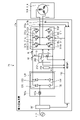
- FIG. 1 is a diagram showing a configuration example of the power conversion device 1 according to the first embodiment.
- the power converter 1 is connected to the commercial power supply 110 and the compressor 315.
- the commercial power supply 110 is an example of an AC power supply
- the compressor 315 is an example of a load.
- the power conversion device 1 converts the first AC power supplied from the commercial power source 110 into the second AC power having a desired amplitude and phase and supplies the first AC power to the compressor 315.
- the power conversion device 1 includes a voltage / current detection unit 501, a converter 700, a smoothing unit 200, an inverter 310, current detectors 313a and 313b, a temperature detector 250, and a control unit 420.
- the motor drive device 2 is configured by the power conversion device 1 and the motor 314 included in the compressor 315.
- the voltage / current detection unit 501 detects the voltage and current of the first AC power supplied from the commercial power supply 110. Each detection value by the voltage / current detection unit 501 is input to the control unit 420.
- the converter 700 includes a rectifying unit 130 and a boosting unit 600.
- the converter 700 rectifies the first AC power supplied from the commercial power source 110 and boosts the voltage of the first AC power.
- the rectifying unit 130 has a bridge circuit composed of rectifying elements 131 to 134.
- the rectifying unit 130 rectifies the voltage of the first AC power supplied from the commercial power supply 110 and outputs it to the boosting unit 600.
- the booster unit 600 has a reactor 120, a switching element 611, and a rectifying element 621.
- the booster unit 600 is connected to the output end of the rectifying unit 130.
- the booster unit 600 boosts the rectified voltage output from the rectifying unit 130, and applies the boosted boosted voltage to the smoothing unit 200.
- the switching element 611 is controlled to be turned on or off by the control signal output from the control unit 420.
- the rectified voltage is shorted via the reactor 120. This operation is called “power short circuit operation”.
- the switching element 611 is controlled off, the rectified voltage is applied to the smoothing section 200 via the reactor 120 and the rectifying element 621. This operation is a normal rectification operation. At this time, if energy is stored in the reactor 120, the rectified voltage and the voltage generated in the reactor 120 are added and applied to the smoothing portion 200.
- the booster unit 600 boosts the rectified voltage by alternately repeating the power short circuit operation and the rectified operation. This operation is called "boost operation".
- boost operation By the boosting operation, the voltage across the smoothing portion 200 is boosted to a voltage higher than the power supply voltage. Further, the boosting operation improves the power factor of the current flowing between the commercial power supply 110 and the converter 700.
- the smoothing portion 200 has a smoothing capacitor 210.
- the smoothing portion 200 is connected to the output end of the converter 700.
- the smoothing capacitor 210 smoothes the voltage applied from the converter 700. Examples of the smoothing capacitor 210 include an electric field capacitor and a film capacitor.
- the smoothing portion 200 is provided with a voltage detector 212 and a current detector 214.
- the voltage detector 212 detects the capacitor voltage Vc, which is the voltage of the smoothing capacitor 210.
- the capacitor voltage Vc is equivalent to the voltage across the smoothing portion 200. Therefore, the voltage across the smoothing portion 200 may be detected by the voltage detector 212 provided outside the smoothing portion 200.
- the current detector 214 detects the first current I1 flowing in and out of the smoothing portion 200. Each detection value of the voltage detector 212 and the current detector 214 is input to the control unit 420.
- the first current I1 defines the direction shown in the figure, that is, the direction in which the discharge current flows in the smoothing capacitor 210 as positive. In this paper, the first current I1 may be referred to as "capacitor current”. Further, in this paper, the current detector 214 may be referred to as a "first current detector”.
- the current flowing out from the converter 700 is further referred to as "I2", and the current flowing into the inverter 310 is referred to as "I3".
- the current I2 is referred to as a "second current” and the current I3 is referred to as a "third current”.
- the orientation shown in the figure is defined as "positive”.
- the inverter 310 is connected to both ends of the smoothing portion 200.
- the inverter 310 has switching elements 311a to 311f and freewheeling diodes 312a to 312f.
- the inverter 310 turns on and off the switching elements 311a to 311f under the control of the control unit 420, converts the power output from the converter 700 and the smoothing unit 200 into a second AC power having a desired amplitude and phase, and compresses the compressor. Output to 315.
- Current detectors 313a and 313b are provided in the electrical wiring connecting the inverter 310 and the motor 314.
- the current detectors 313a and 313b each detect the current of one of the three phases output from the inverter 310.
- Each detected value of the current detectors 313a and 313b is input to the control unit 420.
- the control unit 420 calculates the current of the remaining one phase based on the detected value of the current of any two phases detected by the current detectors 313a and 313b.
- the temperature detector 250 detects the ambient temperature K1, which is the ambient temperature of the smooth portion 200.
- the detection value of the temperature detector 250 is input to the control unit 420.
- a temperature detector is provided on the control board or the circuit board. Therefore, the detection value of the temperature detector provided on the substrate may be used without providing a special temperature detector.
- the compressor 315 is a load having a motor 314 for driving the compressor.
- the motor 314 rotates according to the amplitude and phase of the second AC power supplied from the inverter 310, and performs a compression operation.
- the load torque of the compressor 315 can often be regarded as a constant torque load.
- the control unit 420 controls the operation of the booster unit 600 of the converter 700, specifically, the on / off of the switching element 611 of the booster unit 600, using the detection value detected by each detector. Further, the control unit 420 controls the operation of the inverter 310, specifically, the on / off of the switching elements 311a to 311f of the inverter 310 by using the detection value detected by each detector.
- the control unit 420 controls the operation of the converter 700 and the inverter 310. By controlling the operation of the converter 700, the control unit 420 controls the power factor improvement of the first AC power supplied from the commercial power supply 110 and controls the average voltage of the smoothing capacitor 210 of the smoothing unit 200.
- control unit 420 controls the operation of the inverter 310 so that the power pulsation component contained in the second current I2 flowing out of the converter 700 is included in the third current I3 flowing into the inverter 310.
- the power supply pulsation component is a pulsation component that fluctuates at a frequency twice the commercial power supply frequency. This control reduces the power pulsation component that can occur in the first current I1.
- control unit 420 controls the operation of the converter 700 so that the motor pulsation component contained in the third current I3 flowing into the inverter 310 is included in the second current I2 flowing out of the converter 700.
- the motor pulsation component is a pulsation component that can be generated by fluctuations in load torque. This control reduces the motor pulsation component that can occur in the first current I1.
- control unit 420 does not have to use all the detected values acquired from each detector, and may perform control using some of the detected values.
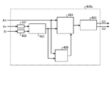
- FIG. 2 is a block diagram showing a configuration example of the control unit 420 according to the first embodiment.
- FIG. 3 is a flowchart showing a processing flow in the control unit 420 of the first embodiment.
- the control unit 420 includes a bandpass filter unit 421 and 422, an ESR calculation unit 423, an ESR change amount estimation unit 424, and a power control unit 425.
- ESR is an abbreviation for Equivalent Series Resistance.
- the input signals to the control unit 420 are the ambient temperature K1, the capacitor voltage Vc, and the first current I1. More specifically, the ambient temperature K1 is input to the ESR change amount estimation unit 424, the capacitor voltage Vc is input to the bandpass filter unit 421, and the first current I1 is input to the bandpass filter unit 422.
- the control unit 420 generates control signals G1 and G2 based on the ambient temperature K1, the capacitor voltage Vc, and the first current I1.
- the control signal G1 is a signal for controlling the switching element 611 of the booster unit 600.
- the control signal G2 is a signal for controlling the switching elements 311a to 311f of the inverter 310.
- the bandpass filter unit 421 extracts a specific frequency component included in the capacitor voltage Vc and outputs it to the ESR calculation unit 423.
- the bandpass filter unit 422 extracts a specific frequency component included in the first current I1 and outputs it to the ESR calculation unit 423.
- the frequency components extracted by the bandpass filter units 421 and 422 are not particularly limited and may be freely set by the user or the designer.
- the specific frequency component may be a switching frequency component for controlling each switching element of the switching element 611 of the booster 600 or the inverter 310. When set in this way, these switching frequency components are surely included in the specific frequency components extracted by the bandpass filter units 421 and 422, so that the effect of increasing the ESR detection accuracy can be obtained.
- the ESR calculation unit 423 performs a complex operation according to Ohm's law based on the outputs of the bandpass filter units 421 and 422, and calculates the ESR of a specific frequency component.
- ESR is an example of a physical quantity determined based on the capacitor voltage Vc and the first current I1.
- the effective value of the physical quantity in the specific frequency component extracted by the bandpass filter units 421 and 422 may be used.
- the calculation result of the ESR calculation unit 423 is output to the ESR change amount estimation unit 424.
- the control unit 420 calculates and acquires the ESR at the time of starting the power conversion device 1 as the initial value of the ESR of the specific frequency component. This calculated value is called “start-up ESR”. Further, the calculated value at the time when the ESR arithmetic processing is performed is referred to as "current ESR”.
- the ESR change amount estimation unit 424 calculates the ESR ratio based on the ambient temperature K1 and the calculation result of the ESR calculation unit 423.
- the ESR ratio is the ratio of the current ESR to the startup ESR, and represents the amount of change in the ESR from the reference time. That is, the ESR change amount estimation unit 424 estimates the change amount of the ESR from the reference time based on the capacitor voltage Vc and the ESR ratio.
- the power control unit 425 controls the operation of at least one of the converter 700 and the inverter 310 based on the amount of change of the ESR from the reference time.
- the power control unit 425 controls to reduce the operating power of at least one of the converter 700 and the inverter 310.
- the power control unit 425 controls to stop the operation of at least one of the converter 700 and the inverter 310. By these controls, the deterioration progress rate of the smoothing capacitor 210 can be slowed down.
- the above-mentioned operation is shown in a flowchart as shown in FIG.
- the control unit 420 calculates the ESR based on the capacitor voltage Vc and the first current I1 (step S11). Next, the control unit 420 estimates the amount of change in the ESR from the reference time based on the reference value of the ESR and the calculated value of the ESR (step S12). Then, the control unit 420 controls the operation of at least one of the inverter and the converter based on the amount of change of the ESR from the reference time (step S13).
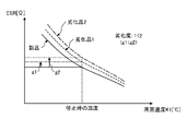
- FIG. 4 is a diagram for explaining the operating principle of the control unit 420 of the first embodiment.
- FIG. 4 shows an example of the characteristics of the electrolytic capacitor exemplified as the smoothing capacitor 210 of the first embodiment.
- FIG. 4 is also a diagram showing an image of a table constructed in the ESR change amount estimation unit 424 of the control unit 420.
- the horizontal axis of FIG. 4 shows the ESR ratio obtained by the ESR calculation unit 423, and the vertical axis shows the capacitor temperature.
- the electrolytic capacitor uniformly has the characteristics as shown in FIG.
- the curve L1 representing the characteristics of the electrolytic capacitor is shown by a solid line.
- the control operation start line L2 is drawn from the position where the capacitor temperature is T1 by a alternate long and short dash line parallel to the horizontal axis. Further, the value on the horizontal axis at the intersection of the curve L1 and the control operation start line L2 is shown as " ⁇ ".
- T1 is the temperature corresponding to the above-mentioned determination value
- ⁇ is the ESR ratio corresponding to the above-mentioned threshold value. Therefore, when the capacitor temperature is higher than the determination value T1, it can be determined that the electrolytic capacitor is likely to deteriorate. Therefore, in the first embodiment, control is performed to delay the progress of deterioration of the electrolytic capacitor when the ESR ratio calculated by the ESR change amount estimation unit 424 is less than the threshold value ⁇ corresponding to the determination value T1.
- the content of the control is as described above.
- the above control is supplemented.
- the threshold value ⁇ to be compared with the ESR ratio corresponds to the determination value T1 for determining the magnitude of the capacitor temperature. Further, determining the threshold value by obtaining the ESR ratio is equivalent to estimating the capacitor temperature and determining the threshold value. Therefore, if the method of the first embodiment is used, the state of the smoothing capacitor 210 can be determined from the estimated capacitor temperature without providing a sensor for detecting the capacitor temperature. That is, if the method of the first embodiment is used, a sensor for detecting the capacitor temperature becomes unnecessary, so that it is possible to reduce the size and cost of the device.
- the initial value of ESR does not have to be at the time of startup, and may be a value acquired at the reference time after startup. That is, the initial value of ESR may be any reference value for evaluating ESR, and any acquired value may be used as long as it is a reference value.
- the method of the first embodiment can be applied as long as the characteristics as shown in FIG. 4 can be grasped. Therefore, the method of the first embodiment can be applied to a capacitor other than the electrolytic capacitor.
- ESR is exemplified as an example of a physical quantity determined based on the capacitor voltage Vc and the capacitor current, but the present invention is not limited to this.
- the impedance of the smoothing capacitor 210 may be used.
- the impedance includes not only the resistance component but also the reactance component, but if the reactance component is known, it is possible to estimate the ESR using the information on the impedance.
- the capacitor capacity of the smoothing capacitor 210 may be used.
- the capacitor capacity is a physical quantity indicating a deterioration state of the capacitor, and can be used in place of ESR.
- a known method can be used to estimate the capacitor capacity.
- the calculation unit provided in the control unit is determined based on the temperature of the smoothing unit, the voltage across the smoothing unit, and the first current flowing in and out of the smoothing unit. Calculate the physical quantity to be calculated. Further, the first estimation unit provided in the control unit estimates the amount of change of the physical quantity from the reference time based on the reference value of the physical quantity and the calculated value of the physical quantity. This makes it possible to appropriately grasp the state of the smoothing capacitor provided in the power conversion device. Further, the control unit controls the operation of at least one of the converter and the inverter based on the amount of change of the physical quantity from the reference time. As a result, the continuous use period of the power conversion device can be extended.
- control unit controls to reduce the operating power of at least one of the converter and the inverter when the amount of change exceeds the threshold value, or the converter and the inverter. Control is performed to stop at least one of these operations. This makes it possible to prevent the smoothing capacitor from failing due to excessive heat generation of the smoothing capacitor.
- FIG. 5 is a block diagram showing an example of a hardware configuration that realizes the function of the control unit 420 according to the first embodiment.
- FIG. 6 is a block diagram showing another example of the hardware configuration that realizes the function of the control unit 420 according to the first embodiment.
- the processor 800 that performs the calculation, the memory 802 in which the program read by the processor 800 is stored,
- the configuration may include an interface 804 for inputting / outputting signals and a display 805 for displaying the processing result of the processor 800.
- the processor 800 may be an arithmetic unit such as an arithmetic unit, a microprocessor, a microcomputer, a CPU (Central Processing Unit), or a DSP (Digital Signal Processor).
- the memory 802 includes a non-volatile or volatile semiconductor such as a RAM (Random Access Memory), a ROM (Read Only Memory), a flash memory, an EPROM (Erasable Project ROM), and an EEPROM (registered trademark) (Electrically EPROM). Examples thereof include magnetic discs, flexible discs, optical discs, compact discs, mini discs, and DVDs (Digital Whatever Disc).
- the memory 802 stores a program that executes the function of the control unit 420 according to the first embodiment.
- the processor 800 sends and receives necessary information via the interface 804, the processor 800 executes a program stored in the memory 802, and the processor 800 refers to a table stored in the memory 802 to perform the above-mentioned processing. It can be carried out.
- the processing result by the processor 800 can be displayed on the display 805. Further, the processing result by the processor 800 can be stored in the memory 802.
- the processing circuit 803 shown in FIG. 6 can also be used.
- the processing circuit 803 corresponds to a single circuit, a composite circuit, an ASIC (Application Specific Integrated Circuit), an FPGA (Field-Programmable Gate Array), or a combination thereof.
- the information input to the processing circuit 803 and the information output from the processing circuit 803 can be obtained via the interface 804.
- the ESR ratio calculated by the ESR change amount estimation unit 424 can be displayed on the display 805. Further, if the calculated ESR ratio is recorded in the memory 802, the past record can be displayed on the display 805 at the time of inspection at a later date. Further, when the control unit 420 has the display 805, it is possible to output an alert to the user or the administrator when the ESR ratio exceeds the threshold value. As a result, maintenance and inspection can be performed only with the power conversion device 1, and there is an advantage that maintenance work becomes easy.
- the threshold value for determining the output of the alert may be different from the threshold value ⁇ to be compared with the ESR ratio described above.
- control unit 420 may be performed by the processing circuit 803, and processing not performed by the processing circuit 803 may be performed by the processor 800 and the memory 802.
- FIG. 7 is a diagram showing a configuration example of the power conversion device 1a according to the first modification of the first embodiment.
- the converter 700 shown in FIG. 1 is replaced with the converter 700a.
- the booster unit 600 is deleted, the reactor 120 of the booster unit 600 is replaced with the reactor 120a, and is arranged between the commercial power supply 110 and the rectifying unit 130.
- the motor drive device 2a is configured by the power conversion device 1a and the motor 314 included in the compressor 315.
- Other configurations are the same as or equivalent to the power conversion device 1 shown in FIG. 1, and the same or equivalent components are designated by the same reference numerals.
- FIG. 8 is a diagram showing a configuration example of the power conversion device 1b according to the second modification of the first embodiment.
- the converter 700 shown in FIG. 1 is replaced with the converter 701.
- the converter 701 is a component having both a rectifying function and a boosting function, similar to the converter 700 shown in FIG.
- the motor drive device 2b is configured by the power conversion device 1b and the motor 314 included in the compressor 315.
- the converter 701 has a reactor 120a, switching elements 611 to 614, and rectifying elements 621 to 624, each of which is connected in parallel to one of the switching elements 611 to 614.
- Other configurations are the same as or equivalent to the power conversion device 1 shown in FIG. 1, and the same or equivalent components are designated by the same reference numerals.
- the switching elements 611 to 614 are controlled to be turned on or off by the control signal output from the control unit 420.
- the converter 701 alternately repeats the power supply short-circuit operation and the rectification operation.
- the converter 701 rectifies and boosts the first AC power output from the commercial power supply 110, and outputs the boosted power to the smoothing unit 200.
- the boosting operation improves the power factor of the current flowing between the commercial power supply 110 and the converter 701.
- FIG. 9 is a diagram showing a configuration example of the power conversion device 1c according to the third modification of the first embodiment.
- the converter 700 shown in FIG. 1 is replaced with the converter 702.
- the booster unit 600 is replaced with the booster unit 601 and the reactor 120a.
- the reactor 120a is arranged between the commercial power supply 110 and the rectifying unit 130.
- the converter 702 is a component having both a rectifying function and a boosting function, similar to the converter 700 shown in FIG.
- the motor drive device 2c is configured by the power conversion device 1c and the motor 314 included in the compressor 315.
- the booster unit 601 has a rectifying element 621 to 624 and a switching element 615.
- the booster unit 601 is connected in parallel with the rectifying unit 130.
- Other configurations are the same as or equivalent to the power conversion device 1 shown in FIG. 1, and the same or equivalent components are designated by the same reference numerals.
- the switching element 615 is controlled to be turned on or off by the control signal output from the control unit 420.
- the booster unit 601 performs a power short-circuit operation.
- the rectifying unit 130 performs a rectifying operation.
- the converter 702 alternately repeats the power supply short-circuit operation and the rectification operation. As a result, the converter 702 rectifies and boosts the first AC power output from the commercial power supply 110, and outputs the boosted power to the smoothing unit 200.
- the boosting operation the voltage across the smoothing portion 200 is boosted to a voltage higher than the power supply voltage. Further, the boosting operation improves the power factor of the current flowing between the commercial power supply 110 and the converter 702.
- FIG. 10 is a block diagram showing a configuration example of the control unit 420a according to the second embodiment.
- a deterioration degree estimation unit 426 is added as compared with the configuration shown in FIG.
- Other configurations are the same as or equivalent to those in FIG. 2, and the same or equivalent components are indicated by the same reference numerals, and duplicate explanations are omitted.
- the control unit 420a according to the second embodiment can be applied to any of the power conversion devices having the configurations shown in FIGS. 1 and 7 to 9.
- the control unit 420a operates the inverter 310 to pass a current through the smoothing unit 200 when the operation of the compressor 315, which is a load, is stopped.
- the ESR calculation unit 423 calculates the ESR based on the capacitor voltage Vc and the first current I1 when a current is passed through the smoothing unit 200.
- the deterioration degree estimation unit 426 estimates the deterioration degree of the smoothing capacitor 210 based on the calculated ESR and the ambient temperature K1. The deterioration degree information estimated by the deterioration degree estimation unit 426 is transmitted to the ESR change amount estimation unit 424.
- the ESR change amount estimation unit 424 calculates the ESR ratio based on the ambient temperature K1, the calculation result of the ESR calculation unit 423, and the degree of deterioration of the smoothing capacitor 210. Subsequent operations are the same as those in the first embodiment.
- FIG. 11 is a diagram for explaining the operating principle of the control unit 420a of the second embodiment.
- FIG. 11 shows characteristics different from those of FIG. 4 of the electrolytic capacitor exemplified as the smoothing capacitor 210 of the first embodiment.
- FIG. 11 is also a diagram showing an image of a table constructed in the deterioration degree estimation unit 426 of the control unit 420a.
- the horizontal axis of FIG. 11 shows the ambient temperature K1, and the vertical axis shows the ESR.
- the solid line represents the characteristics of the new electrolytic capacitor
- the broken line represents the characteristics of the electrolytic capacitor of the deteriorated product 1
- the alternate long and short dash line represents the characteristics of the electrolytic capacitor of the deteriorated product 2.
- the deteriorated product 1 and the deteriorated product 2 it is shown that the deteriorated product 2 is in a more deteriorated state than the deteriorated product 1.
- the value of ESR fluctuates with respect to the ambient temperature K1. Therefore, in the second embodiment, the inverter 310 is operated with the load operation stopped, and a current is passed through the smoothing portion 200. By stopping the operation of the load, fluctuations in the capacitor temperature are suppressed. If the ESR is calculated in this state, the calculation accuracy of the ESR can be improved.
- the deterioration coefficient g is calculated as an example of the degree of deterioration.
- the deterioration coefficient g is a ratio between the ESR of the smoothing capacitor 210 calculated in a state where the operation of the load is stopped and the ESR when the smoothing capacitor 210 is new.
- the deterioration coefficient g is a real value of 1 or more, and is a coefficient representing an increase in ESR.
- FIG. 11 the deterioration coefficient g1 of the deteriorated product 1 and the deterioration coefficient g2 of the deteriorated product 2 are shown.
- the deteriorated product 2 is in a more deteriorated state than the deteriorated product 1, there is a relationship of g1 ⁇ g2 between the deterioration coefficients g1 and g2.
- the ESR change amount estimation unit 424 receives the information of the deterioration coefficient g and corrects the characteristics of the curve L1 shown in FIG. 4 based on the deterioration coefficient g. Correcting the characteristics of the curve L1 is equivalent to correcting the table constructed in the ESR change amount estimation unit 424. As a result, the accuracy of estimating the amount of change in ESR can be improved.
- the ESR is calculated by operating the inverter 310 and passing a current through the smoothing portion 200 when the operation of the compressor 315 is stopped, but the present invention is not limited to this.
- the converter 700 may be operated and a current may be passed from the converter 700 to the smoothing portion 200 to calculate the ESR.
- the ESR may be calculated by passing a power supply current from the commercial power supply 110 to the smoothing portion 200 via the converter 700.
- the reference value for calculating the deterioration coefficient g is ESR when the smoothing capacitor 210 is new
- the present invention is not limited to this.
- the ESR calculated or measured at the time of the first use of the product equipped with the power conversion device 1 may be set as the reference value.
- the control unit is detected when the operation of the load is stopped and the inverter is operated to pass a current through the smooth unit.
- the amount of increase in ESR is calculated based on the voltage across the ends and the first current.
- the degree of deterioration of the smoothing capacitor is estimated based on the calculated increase in ESR.
- the control unit operates the capacitor to operate the capacitor to pass a current from the converter to the smoothing unit when the load operation is stopped, and the voltage across the control unit is detected.
- the amount of increase in ESR is calculated based on one current.
- the degree of deterioration of the smoothing capacitor is estimated based on the calculated increase in ESR.
- the control unit detects the voltage across the cable and the voltage across the control unit when the power supply current is passed from the AC power supply to the smooth unit via the converter when the operation of the load is stopped.
- the amount of increase in ESR is calculated based on the first current.
- the degree of deterioration of the smoothing capacitor is estimated based on the calculated increase in ESR.
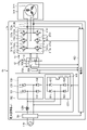
- FIG. 12 is a diagram showing a configuration example of the power conversion device 1d according to the third embodiment.
- the smooth portion 200 shown in FIG. 1 is replaced with the smooth portion 200d.
- the current detector 214 shown in FIG. 1 is deleted.
- the control unit 420 shown in FIG. 1 is replaced with the control unit 420b.
- a current detector 222 for detecting the second current I2 and a current detector 224 for detecting the third current I3 are added.
- the motor drive device 2d is configured by the power conversion device 1d and the motor 314 included in the compressor 315. Other configurations are the same as or equivalent to those of the power conversion device 1 shown in FIG.
- the current detector 222 may be referred to as a "second current detector”
- the current detector 224 may be referred to as a "third current detector”.
- FIG. 13 is a block diagram showing a configuration example of the control unit 420b according to the third embodiment.
- an adder / subtractor 427 is added as compared with the configuration shown in FIG.
- Other configurations are the same as or equivalent to those in FIG. 2, and the same or equivalent components are indicated by the same reference numerals, and duplicate explanations are omitted.
- the input signals to the control unit 420b are the ambient temperature K1, the capacitor voltage Vc, the second current I2, and the third current I3.
- the control unit 420b generates the first current I1 by calculating the difference value between the third current I3 and the second current I2 with the adder / subtractor 427. Subsequent operations are the same as those in the first embodiment.
- the current detector 214 can be omitted from the configuration of FIG.
- a general power conversion device includes a current detector 222 for detecting the second current I2 and a current detector 224 for detecting the third current I3. Therefore, as compared with the power conversion device 1 shown in FIG. 1, the effect that the manufacturing cost can be reduced can be obtained.
- the configuration in which the current detector 214 is omitted and the current detectors 222 and 224 are added is applied to the power conversion device 1 shown in FIG. 1, but the present invention is not limited to this. These configurations may be applied to the power conversion devices 1a to 1c shown in FIGS. 7 to 9.
- the configuration in which the adder / subtractor 427 is added is applied to the control unit 420 shown in FIG. 2, but it may be applied to the control unit 420a shown in FIG.
- FIG. 14 is a diagram showing a configuration example of the refrigeration cycle application device 900 according to the fourth embodiment.
- the refrigeration cycle application device 900 according to the fourth embodiment includes the power conversion device 1 described in the first embodiment.
- the refrigeration cycle application device 900 may include the power conversion devices 1a to 1c described in the modified example of the first embodiment instead of the power conversion device 1.
- the power conversion device 1d described in the third embodiment may be provided.
- the refrigeration cycle application device 900 according to the fourth embodiment can be applied to products including a refrigeration cycle such as an air conditioner, a refrigerator, a freezer, and a heat pump water heater.
- the components having the same functions as those of the first embodiment are designated by the same reference numerals as those of the first embodiment.
- the compressor 315 having a built-in motor 314, the four-way valve 902, the indoor heat exchanger 906, the expansion valve 908, and the outdoor heat exchanger 910 form the refrigerant pipe 912 according to the first embodiment. It is attached via.
- a compression mechanism 904 for compressing the refrigerant and a motor 314 for operating the compression mechanism 904 are provided inside the compressor 315.
- the refrigeration cycle applicable device 900 can perform heating operation or cooling operation by switching operation of the four-way valve 902.
- the compression mechanism 904 is driven by a variable speed controlled motor 314.
- the refrigerant is pressurized by the compression mechanism 904 and sent out, and passes through the four-way valve 902, the indoor heat exchanger 906, the expansion valve 908, the outdoor heat exchanger 910 and the four-way valve 902. Return to the compression mechanism 904.
- the refrigerant is pressurized by the compression mechanism 904 and sent out, and passes through the four-way valve 902, the outdoor heat exchanger 910, the expansion valve 908, the indoor heat exchanger 906 and the four-way valve 902. Return to the compression mechanism 904.
- the indoor heat exchanger 906 acts as a condenser to release heat, and the outdoor heat exchanger 910 acts as an evaporator to absorb heat.
- the outdoor heat exchanger 910 acts as a condenser to release heat, and the indoor heat exchanger 906 acts as an evaporator to absorb heat.
- the expansion valve 908 depressurizes the refrigerant and expands it.
- the configuration shown in the above embodiments is an example, and can be combined with another known technique, can be combined with each other, and does not deviate from the gist. It is also possible to omit or change a part of the configuration.
Landscapes
- Engineering & Computer Science (AREA)
- Power Engineering (AREA)
- Inverter Devices (AREA)
Priority Applications (2)
| Application Number | Priority Date | Filing Date | Title |
|---|---|---|---|
| JP2022573834A JP7499886B2 (ja) | 2021-01-06 | 2021-01-06 | 電力変換装置、モータ駆動装置及び冷凍サイクル適用機器 |
| PCT/JP2021/000194 WO2022149208A1 (ja) | 2021-01-06 | 2021-01-06 | 電力変換装置、モータ駆動装置及び冷凍サイクル適用機器 |
Applications Claiming Priority (1)
| Application Number | Priority Date | Filing Date | Title |
|---|---|---|---|
| PCT/JP2021/000194 WO2022149208A1 (ja) | 2021-01-06 | 2021-01-06 | 電力変換装置、モータ駆動装置及び冷凍サイクル適用機器 |
Publications (1)
| Publication Number | Publication Date |
|---|---|
| WO2022149208A1 true WO2022149208A1 (ja) | 2022-07-14 |
Family
ID=82358182
Family Applications (1)
| Application Number | Title | Priority Date | Filing Date |
|---|---|---|---|
| PCT/JP2021/000194 Ceased WO2022149208A1 (ja) | 2021-01-06 | 2021-01-06 | 電力変換装置、モータ駆動装置及び冷凍サイクル適用機器 |
Country Status (2)
| Country | Link |
|---|---|
| JP (1) | JP7499886B2 (https=) |
| WO (1) | WO2022149208A1 (https=) |
Cited By (1)
| Publication number | Priority date | Publication date | Assignee | Title |
|---|---|---|---|---|
| WO2025182075A1 (ja) * | 2024-03-01 | 2025-09-04 | 三菱電機株式会社 | 電力変換装置、モータ駆動装置及び空気調和装置 |
Citations (10)
| Publication number | Priority date | Publication date | Assignee | Title |
|---|---|---|---|---|
| JPH1014097A (ja) * | 1996-06-18 | 1998-01-16 | Hitachi Ltd | 電力変換器のコンデンサ容量判定装置 |
| JP2001309561A (ja) * | 2000-04-24 | 2001-11-02 | Mitsubishi Electric Corp | 連系装置 |
| JP2007318838A (ja) * | 2006-05-23 | 2007-12-06 | Daikin Ind Ltd | 制御装置 |
| JP2015106961A (ja) * | 2013-11-29 | 2015-06-08 | ダイキン工業株式会社 | 電力変換装置 |
| JP2016027774A (ja) * | 2014-06-23 | 2016-02-18 | 東芝キヤリア株式会社 | 電力変換装置及び電力変換システム |
| JP2016178823A (ja) * | 2015-03-20 | 2016-10-06 | ファナック株式会社 | 直流コンデンサの寿命判定手段を有するモータ駆動装置 |
| JP2017108562A (ja) * | 2015-12-10 | 2017-06-15 | 株式会社東芝 | 車両用制御装置 |
| JP2018102082A (ja) * | 2016-12-21 | 2018-06-28 | ファナック株式会社 | モータ駆動装置 |
| JP2019161757A (ja) * | 2018-03-08 | 2019-09-19 | ナブテスコ株式会社 | Ac−ac電力変換装置 |
| JP2020527024A (ja) * | 2017-10-24 | 2020-08-31 | ミツビシ・エレクトリック・アールアンドディー・センター・ヨーロッパ・ビーヴィMitsubishi Electric R&D Centre Europe B.V. | Dcバスコンデンサをオンラインモニタリングする方法及び装置 |
-
2021
- 2021-01-06 WO PCT/JP2021/000194 patent/WO2022149208A1/ja not_active Ceased
- 2021-01-06 JP JP2022573834A patent/JP7499886B2/ja active Active
Patent Citations (10)
| Publication number | Priority date | Publication date | Assignee | Title |
|---|---|---|---|---|
| JPH1014097A (ja) * | 1996-06-18 | 1998-01-16 | Hitachi Ltd | 電力変換器のコンデンサ容量判定装置 |
| JP2001309561A (ja) * | 2000-04-24 | 2001-11-02 | Mitsubishi Electric Corp | 連系装置 |
| JP2007318838A (ja) * | 2006-05-23 | 2007-12-06 | Daikin Ind Ltd | 制御装置 |
| JP2015106961A (ja) * | 2013-11-29 | 2015-06-08 | ダイキン工業株式会社 | 電力変換装置 |
| JP2016027774A (ja) * | 2014-06-23 | 2016-02-18 | 東芝キヤリア株式会社 | 電力変換装置及び電力変換システム |
| JP2016178823A (ja) * | 2015-03-20 | 2016-10-06 | ファナック株式会社 | 直流コンデンサの寿命判定手段を有するモータ駆動装置 |
| JP2017108562A (ja) * | 2015-12-10 | 2017-06-15 | 株式会社東芝 | 車両用制御装置 |
| JP2018102082A (ja) * | 2016-12-21 | 2018-06-28 | ファナック株式会社 | モータ駆動装置 |
| JP2020527024A (ja) * | 2017-10-24 | 2020-08-31 | ミツビシ・エレクトリック・アールアンドディー・センター・ヨーロッパ・ビーヴィMitsubishi Electric R&D Centre Europe B.V. | Dcバスコンデンサをオンラインモニタリングする方法及び装置 |
| JP2019161757A (ja) * | 2018-03-08 | 2019-09-19 | ナブテスコ株式会社 | Ac−ac電力変換装置 |
Cited By (1)
| Publication number | Priority date | Publication date | Assignee | Title |
|---|---|---|---|---|
| WO2025182075A1 (ja) * | 2024-03-01 | 2025-09-04 | 三菱電機株式会社 | 電力変換装置、モータ駆動装置及び空気調和装置 |
Also Published As
| Publication number | Publication date |
|---|---|
| JPWO2022149208A1 (https=) | 2022-07-14 |
| JP7499886B2 (ja) | 2024-06-14 |
Similar Documents
| Publication | Publication Date | Title |
|---|---|---|
| US9625190B2 (en) | Motor driving device and air conditioner including the same | |
| US9534823B2 (en) | Motor driving device and air conditioner including the same | |
| JP7345674B2 (ja) | 電力変換装置、モータ駆動装置および冷凍サイクル適用機器 | |
| JP7345673B2 (ja) | 電力変換装置、モータ駆動装置および冷凍サイクル適用機器 | |
| WO2017056298A1 (ja) | 電力変換装置及びこれを用いた空気調和装置 | |
| JP4416486B2 (ja) | モータ制御装置 | |
| JP7387038B2 (ja) | 電力変換装置、モータ駆動装置および空気調和機 | |
| WO2022091186A1 (ja) | 電力変換装置、モータ駆動装置および冷凍サイクル適用機器 | |
| KR20140112297A (ko) | 전력변환장치, 및 이를 구비하는 공기조화기 | |
| JP7378651B2 (ja) | 電力変換装置、モータ駆動装置及び冷凍サイクル適用機器 | |
| JP2018182939A (ja) | 電源装置 | |
| WO2022149208A1 (ja) | 電力変換装置、モータ駆動装置及び冷凍サイクル適用機器 | |
| JP2017208979A (ja) | 電源装置 | |
| KR20140108956A (ko) | 전력변환장치 및 이를 포함하는 공기조화기 | |
| WO2022172418A1 (ja) | 電力変換装置、モータ駆動装置および冷凍サイクル適用機器 | |
| WO2023100359A1 (ja) | 電力変換装置、モータ駆動装置および冷凍サイクル適用機器 | |
| WO2023100360A1 (ja) | 電力変換装置、モータ駆動装置および冷凍サイクル適用機器 | |
| WO2023095264A1 (ja) | 電力変換装置、モータ駆動装置及び冷凍サイクル適用機器 | |
| JP6505264B2 (ja) | 電力変換装置およびこれを用いた空気調和装置 | |
| KR20140112298A (ko) | 전력변환장치, 및 이를 구비하는 공기조화기 | |
| KR20090081914A (ko) | 공기조화기의 전동기 제어장치 | |
| KR102302240B1 (ko) | 전력 변환 장치 및 제어 방법, 이를 이용한 공기조화기 | |
| WO2024176332A1 (ja) | 電力変換装置、モータ駆動装置及び冷凍サイクル適用機器 | |
| JP7345690B2 (ja) | 電力変換装置、モータ駆動装置及び冷凍サイクル適用機器 | |
| WO2023238229A1 (ja) | 電力変換装置、モータ駆動装置及び冷凍サイクル適用機器 |
Legal Events
| Date | Code | Title | Description |
|---|---|---|---|
| 121 | Ep: the epo has been informed by wipo that ep was designated in this application |
Ref document number: 21917436 Country of ref document: EP Kind code of ref document: A1 |
|
| ENP | Entry into the national phase |
Ref document number: 2022573834 Country of ref document: JP Kind code of ref document: A |
|
| NENP | Non-entry into the national phase |
Ref country code: DE |
|
| 122 | Ep: pct application non-entry in european phase |
Ref document number: 21917436 Country of ref document: EP Kind code of ref document: A1 |