WO2022131201A1 - 車両用ディスクブレーキのキャリパボディ - Google Patents
車両用ディスクブレーキのキャリパボディ Download PDFInfo
- Publication number
- WO2022131201A1 WO2022131201A1 PCT/JP2021/045787 JP2021045787W WO2022131201A1 WO 2022131201 A1 WO2022131201 A1 WO 2022131201A1 JP 2021045787 W JP2021045787 W JP 2021045787W WO 2022131201 A1 WO2022131201 A1 WO 2022131201A1
- Authority
- WO
- WIPO (PCT)
- Prior art keywords
- vehicle
- mount type
- caliper
- caliper half
- vehicle body
- Prior art date
- Legal status (The legal status is an assumption and is not a legal conclusion. Google has not performed a legal analysis and makes no representation as to the accuracy of the status listed.)
- Ceased
Links
Images






Classifications
-
- F—MECHANICAL ENGINEERING; LIGHTING; HEATING; WEAPONS; BLASTING
- F16—ENGINEERING ELEMENTS AND UNITS; GENERAL MEASURES FOR PRODUCING AND MAINTAINING EFFECTIVE FUNCTIONING OF MACHINES OR INSTALLATIONS; THERMAL INSULATION IN GENERAL
- F16D—COUPLINGS FOR TRANSMITTING ROTATION; CLUTCHES; BRAKES
- F16D55/00—Brakes with substantially-radial braking surfaces pressed together in axial direction, e.g. disc brakes
- F16D55/02—Brakes with substantially-radial braking surfaces pressed together in axial direction, e.g. disc brakes with axially-movable discs or pads pressed against axially-located rotating members
- F16D55/22—Brakes with substantially-radial braking surfaces pressed together in axial direction, e.g. disc brakes with axially-movable discs or pads pressed against axially-located rotating members by clamping an axially-located rotating disc between movable braking members, e.g. movable brake discs or brake pads
- F16D55/228—Brakes with substantially-radial braking surfaces pressed together in axial direction, e.g. disc brakes with axially-movable discs or pads pressed against axially-located rotating members by clamping an axially-located rotating disc between movable braking members, e.g. movable brake discs or brake pads with a separate actuating member for each side
-
- B—PERFORMING OPERATIONS; TRANSPORTING
- B60—VEHICLES IN GENERAL
- B60T—VEHICLE BRAKE CONTROL SYSTEMS OR PARTS THEREOF; BRAKE CONTROL SYSTEMS OR PARTS THEREOF, IN GENERAL; ARRANGEMENT OF BRAKING ELEMENTS ON VEHICLES IN GENERAL; PORTABLE DEVICES FOR PREVENTING UNWANTED MOVEMENT OF VEHICLES; VEHICLE MODIFICATIONS TO FACILITATE COOLING OF BRAKES
- B60T17/00—Component parts, details, or accessories of power brake systems not covered by groups B60T8/00, B60T13/00 or B60T15/00, or presenting other characteristic features
- B60T17/04—Arrangements of piping, valves in the piping, e.g. cut-off valves, couplings or air hoses
-
- F—MECHANICAL ENGINEERING; LIGHTING; HEATING; WEAPONS; BLASTING
- F16—ENGINEERING ELEMENTS AND UNITS; GENERAL MEASURES FOR PRODUCING AND MAINTAINING EFFECTIVE FUNCTIONING OF MACHINES OR INSTALLATIONS; THERMAL INSULATION IN GENERAL
- F16D—COUPLINGS FOR TRANSMITTING ROTATION; CLUTCHES; BRAKES
- F16D65/00—Parts or details
- F16D65/005—Components of axially engaging brakes not otherwise provided for
- F16D65/0068—Brake calipers
-
- F—MECHANICAL ENGINEERING; LIGHTING; HEATING; WEAPONS; BLASTING
- F16—ENGINEERING ELEMENTS AND UNITS; GENERAL MEASURES FOR PRODUCING AND MAINTAINING EFFECTIVE FUNCTIONING OF MACHINES OR INSTALLATIONS; THERMAL INSULATION IN GENERAL
- F16D—COUPLINGS FOR TRANSMITTING ROTATION; CLUTCHES; BRAKES
- F16D65/00—Parts or details
- F16D65/02—Braking members; Mounting thereof
-
- F—MECHANICAL ENGINEERING; LIGHTING; HEATING; WEAPONS; BLASTING
- F16—ENGINEERING ELEMENTS AND UNITS; GENERAL MEASURES FOR PRODUCING AND MAINTAINING EFFECTIVE FUNCTIONING OF MACHINES OR INSTALLATIONS; THERMAL INSULATION IN GENERAL
- F16D—COUPLINGS FOR TRANSMITTING ROTATION; CLUTCHES; BRAKES
- F16D55/00—Brakes with substantially-radial braking surfaces pressed together in axial direction, e.g. disc brakes
- F16D2055/0004—Parts or details of disc brakes
- F16D2055/0016—Brake calipers
-
- F—MECHANICAL ENGINEERING; LIGHTING; HEATING; WEAPONS; BLASTING
- F16—ENGINEERING ELEMENTS AND UNITS; GENERAL MEASURES FOR PRODUCING AND MAINTAINING EFFECTIVE FUNCTIONING OF MACHINES OR INSTALLATIONS; THERMAL INSULATION IN GENERAL
- F16D—COUPLINGS FOR TRANSMITTING ROTATION; CLUTCHES; BRAKES
- F16D55/00—Brakes with substantially-radial braking surfaces pressed together in axial direction, e.g. disc brakes
- F16D2055/0004—Parts or details of disc brakes
- F16D2055/0016—Brake calipers
- F16D2055/002—Brake calipers assembled from a plurality of parts
-
- F—MECHANICAL ENGINEERING; LIGHTING; HEATING; WEAPONS; BLASTING
- F16—ENGINEERING ELEMENTS AND UNITS; GENERAL MEASURES FOR PRODUCING AND MAINTAINING EFFECTIVE FUNCTIONING OF MACHINES OR INSTALLATIONS; THERMAL INSULATION IN GENERAL
- F16D—COUPLINGS FOR TRANSMITTING ROTATION; CLUTCHES; BRAKES
- F16D2125/00—Components of actuators
- F16D2125/02—Fluid-pressure mechanisms
- F16D2125/08—Seals, e.g. piston seals
Definitions
- the present invention relates to a caliper body of a vehicle disc brake, and more particularly to a split type caliper body formed by connecting a pair of caliper halves arranged on both sides of a disc rotor at a bridge portion.
- a split type caliper body formed by connecting a pair of caliper halves arranged on both sides of a disc rotor at a bridge portion, the caliper halves arranged on the opposite side of the disc rotor are formed in the radial direction of the disc.
- a radial mount type vehicle body mounting portion having an insertion hole for a vehicle body mounting bolt see, for example, Patent Document 1
- an axial mount type vehicle body mounting portion having an insertion hole for a vehicle body mounting bolt in the disc axial direction for example, see Patent Document 2.
- each caliper body is designed and manufactured. Was there.
- the present invention is a radial mount type anti-vehicle body side caliper half body having a radial mount type vehicle body mounting portion on the vehicle body side caliper half body, or an axial mount type anti-vehicle body side caliper having an axial mount type vehicle body mounting portion. It is an object of the present invention to provide a caliper body of a disc brake for a vehicle in which either one of the halves can be selectively assembled.
- the caliper body of the disc brake for a vehicle of the present invention is a radial mount type vehicle body on the opposite vehicle body side of the disc rotor with respect to the vehicle body side caliper half body arranged on the vehicle body side of the disc rotor.
- Either the radial mount type anti-body side caliper half body with the mounting part or the axial mount type anti-body side caliper half body with the axial mount type body mounting part is joined via their respective joint surfaces.
- a caliper body of a vehicle disc brake that can be selectively assembled by fastening with a connecting bolt, the body side caliper half body, the radial mount type anti-body side caliper half body, and the axial mount.
- the type anti-vehicle body side caliper half body is a radial mount type anti-vehicle body side caliper in which introduction holes for the hydraulic fluid for introducing the hydraulic fluid into the cylinder hole are formed from the joint surface toward the bottom side of the cylinder hole.
- the introduction hole formed in the half body and the introduction hole formed in the axially mounted anti-vehicle body side caliper half body are the introduction holes formed in the vehicle body side caliper half body at the joint surface, respectively. It is characterized by being formed so as to communicate with each other.
- the radial mount type anti-vehicle body side caliper half body and the axial mount type anti-vehicle body side caliper half body have a seal groove provided on the outer periphery of the opening of the introduction hole opened in the joint surface and a hydraulic fluid. It is preferable to have either one of the union hole introduced into the introduction hole or the bleeder hole for discharging the air in the hydraulic fluid, and the female screw hole for fastening the connecting bolt.
- the body side caliper half body, the radial mount type anti-body side caliper half body, and the axial mount type anti-body side caliper half body are the joint surfaces of the caliper half body.
- an introduction hole for the hydraulic fluid that introduces the hydraulic fluid into the cylinder hole is formed, and an introduction hole formed in the radial mount type anti-vehicle body side caliper half body and an axial mount type anti-vehicle body.
- the introduction hole formed in the side caliper half body is formed so as to communicate with the introduction hole formed in the vehicle body side caliper half body at the joint surface, it is a radial mount type on the vehicle body side caliper half body. Regardless of whether the anti-body side caliper half body or the axial mount type anti-body side caliper half body is joined, the introduction holes communicate with each other and the hydraulic fluid can be supplied to each cylinder hole.
- either the radial mount type anti-body side caliper half body or the axial mount type anti-body side caliper half body can be selectively assembled to the vehicle body side caliper half body, so that the mounting type to the vehicle body is Even if the caliper bodies are different, the same caliper half body on the vehicle body side can be used, and the cost can be reduced.
- the radial mount type anti-vehicle body side caliper half body and the axial mount type anti-vehicle body side caliper half body are provided with a seal groove provided on the outer periphery of the opening of the introduction hole opened on the joint surface, and the hydraulic fluid is introduced into the introduction hole.
- the shape of the caliper half on the vehicle body side should be as simple as possible by having either one of the union hole or the bleeder hole for discharging the air in the hydraulic fluid and the female screw hole for fastening the connecting bolt. It is possible to further reduce costs.
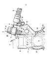
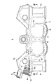
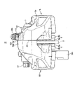
- FIG. 6 is a sectional view taken along line VV of FIG.
- FIG. 1 is a sectional view taken along line VI-VI of FIG.
- FIG. 2 is a cross-sectional view taken along the line VII-VII of FIG. It is a front view of the main part in the state where the union bolt and the hose banjo are attached to the union hole.
- FIG. 8 is a cross-sectional view taken along the line XX of FIG. It is a front view of the caliper body which shows the 1st Embodiment example of this invention. It is a rear view of the caliper half body on the anti-body side. 11 is a cross-sectional view taken along the line XIII-XIII of FIG. It is a front view of the caliper body on the vehicle body side. It is a rear view of the caliper half body on the vehicle body side.
- FIG. 15 is a cross-sectional view taken along the line XVI-XVI of FIG.
- FIGS. 1 to 16 show a vehicle disc brake using a radial mount type anti-body side caliper half body for the caliper body.
- 17 and 18 show a disc brake for a vehicle using a caliper body in which a radial mount type anti-body side caliper half body is recombined with an axial mount type anti-body side caliper half body.
- the arrow A indicates the rotation direction of the disc rotor that rotates integrally with the wheel when the vehicle is moving forward, and the disc turning side and the disc turning side described below are assumed to be when the vehicle is moving forward.
- the vehicle disc brake 1 includes a disc rotor 2 that rotates integrally with a wheel (not shown) in the direction of arrow A, and a caliper body that is attached to the vehicle body by one side of the disc rotor 2. 3 and a pair of friction pads 4 and 4 arranged inside the caliper body 3 so as to face each other with the disc rotor 2 interposed therebetween.
- the vehicle body side caliper half body 5 divided by the bridge portion 3a straddling the outer peripheral side of the disc rotor 2 and the radial mount type anti-vehicle body side caliper half body 6 are integrally formed by two connecting bolts 7 and 7. It is formed by connecting.
- the vehicle body side caliper half body 5 has an action portion 5b having cylinder holes 5a and 5a arranged side by side in the disk circumferential direction, and a bridge portion half body 5c constituting substantially half of the bridge portion 3a, and is a radial mount.
- the anti-vehicle body side caliper half body 6 also has an action portion 6b having cylinder holes 6a and 6a arranged side by side in the disk circumferential direction, and a bridge constituting substantially half of the bridge portion 3a. It has a half body 6c.
- the length of the bridge portion half body 6c of the radial mount type anti-body side caliper half body 6 in the disk axial direction is formed longer than the length of the bridge portion half body 5c of the vehicle body side caliper half body 5 in the disk axial direction.
- the pistons 9 and 9 are inserted into the cylinder holes 5a and 5a, and the hydraulic fluid is introduced between the bottom side of the cylinder holes 5a and 5a and the pistons 9 and 9. , 10 are defined.
- the first hydraulic fluid introduction hole 11 is directed toward the hydraulic chamber 10 of the cylinder hole 5a on the disk rotation side from the split surface which is the joint surface 8 on the disk rotation side of the bridge portion half body 5c. A hole) is drilled.
- first contouring processing section 5d that connects the hydraulic chamber 10 on the disk ejection side and the first hydraulic fluid introduction hole 11 by contouring, and the disk insertion. It has a second contouring processing portion 5e that is contouring toward the hydraulic chamber 10 on the side. Further, at the bottom of the cylinder hole 5a on the disk entry side, a third contouring processing portion 5f to be contoured is formed toward the second contouring processing portion 5e, and the second contouring processing portion 5e and the second contouring processing portion 5e are formed. By communicating with the third contouring processing portion 5f, the first hydraulic fluid introduction hole 11 communicates with the hydraulic pressure chamber 10 on the disk feeding side and the hydraulic pressure chamber 10 on the disc feeding side.
- a bleeder hole 12 that opens to the outer end surface 5g in the radial direction of the disk and communicates with the first hydraulic fluid introduction hole 11 is provided. It is provided.
- the bleeder hole 12 is formed with a female screw portion 12a for screwing the bleeder screw 13 on the opening side, and a mounting seat surface 5h of the bleeder screw 13 is formed on the outer end surface 5g in the radial direction of the disk on the outer periphery of the opening.
- the bleeder screw 13 is provided with an air discharge hole on the inner peripheral portion and a male screw portion 13a screwed on the female screw portion 12a on the outer peripheral portion, and a rubber bleeder cap 13b is attached to the tip head.
- the radial mount type anti-vehicle body side caliper half body 6 has pistons 14 and 14 inserted into the cylinder holes 6a and 6a, and the bottom side of the cylinder holes 6a and 6a and the pistons 14 and 14
- the hydraulic chambers 15 and 15 are defined between the two.
- a second hydraulic fluid introduction hole 16 is formed from the divided surface of the bridge portion half body 6c, which is the joint surface 8 on the disk ejection side, toward the hydraulic chamber 15 on the disk ejection side.
- the first hydraulic fluid introduction hole 11 and the second hydraulic fluid introduction hole 16 communicate with each other at the joint surface 8.
- a seal groove 17a is provided on the outer periphery of the opening where the second hydraulic fluid introduction hole 16 opens to the joint surface 8, and the seal member 17 is mounted in the seal groove 17a.
- a fourth contouring processing section 6d that allows the hydraulic chamber 15 on the disk ejection side and the second hydraulic fluid introduction hole 16 to communicate with each other by contouring, and the disk insertion. It has a fifth contouring processing portion 6e that is contouring toward the hydraulic chamber 15 on the side.
- a sixth contouring processing portion 6f to be contoured is formed toward the fifth contouring processing portion 6e, and the fifth contouring processing portion 6e and the fifth contouring processing portion 6e are formed.
- the second hydraulic fluid introduction hole 16 communicates with the hydraulic pressure chamber 15 on the disk feeding side and the hydraulic pressure chamber 15 on the disc feeding side.
- the disk ejection side end portion of the bridge portion half body 6c is provided with a union hole 18 that opens to the disk ejection side end surface 6g and communicates with the second hydraulic fluid introduction hole 16.
- the union hole 18 is formed with a female screw portion 18a for screwing the union bolt 19 on the opening side, and a mounting seat surface 6h of the union bolt 19 is formed on the disc rotation side end surface 6g on the outer periphery of the opening.
- a hose banjo 21 fixed to the end of the brake hose 20 is attached to the union bolt 19, and a detent portion 6i of the hose banjo 21 is formed on the outer periphery of the mounting seat surface 6h.
- the detent portion 6i protrudes from the outer peripheral side of the mounting seat surface 6h, cuts out a wall portion 6j for protecting the connection between the union bolt 19 and the hose banjo 21, and a part of the wall portion 6j, and cuts out a hose.
- a hose banjo 21 is provided with an engaging portion 6k for preventing the banjo 21 from rotating, and the hose banjo 21 does not rotate together when the union bolt 19 is screwed into the union hole 18 by sandwiching the hose banjo 21 in the engaging portion 6k. I am doing it.
- the union bolt 19 includes a male screw portion 19a to be screwed into the female screw portion 18a and a hexagonal head 19b.
- a liquid passage hole 19c is formed inside the male screw portion 19a, and the brake hose 20 is provided via the union bolt 19. It communicates with the union hole 18.
- radial mount type vehicle body mounting portions 6n and 6n provided with mounting bolt insertion holes 6m and 6m in the radial direction of the disk are provided.
- the caliper body 3 is attached to the vehicle body by screwing the mounting bolts formed and inserted into the mounting bolt insertion holes 6 m and 6 m into the caliper mounting portion provided on the vehicle body side.
- the caliper body 3 has a bolt insertion hole 7a formed in the vehicle body side caliper half body 5 by joining the vehicle body side caliper half body 5 and the radial mount type anti-vehicle body side caliper half body 6 formed in this way at a bridge portion 3a.
- the connecting bolts 7, 7 inserted through 7a to the female screw holes 7b, 7b formed in the radial mount type anti-vehicle body side caliper half body 6, the first hydraulic fluid introduction hole 11 and the second hydraulic fluid introduction hole 11 are fastened.
- Each friction pad 4 is composed of a lining 4a that is in sliding contact with the side surface of the disc rotor 2 and a metal back plate 4b to which the lining 4a is attached.
- a hanging piece 4c is extended in the center of the upper part of the back plate 4b, and a hanger pin 22 is inserted through the hanging piece 4c.
- the hanger pin 22 is erected in the disc axial direction on both acting portions 5b and 6b through the ceiling opening 3b formed in the bridge portion 3a of the caliper body 3, and the vehicle body side caliper half body 5 and the radial mount type anti-vehicle body side caliper.
- a pad spring 23 is provided over the back plate 4b, the bridge portion 3a, and the hanger pin 22, and presses the friction pads 4 and 4 toward the disk rotation side and the inside in the disk radial direction.
- the vehicle disc brake 31 shown in FIGS. 17 and 18 uses a caliper body 33 formed by replacing the above-mentioned radial mount type anti-body side caliper half body 6 with an axial mount type anti-body side caliper half body 32. There is.
- a hydraulic chamber (shown) is provided between the bottom side of the cylinder holes 32a and 32a and the pistons 34 and 34.
- Z is defined.
- a second hydraulic fluid introduction hole 36 (introduction hole of the present invention) is formed from the split surface of the bridge portion half body 32b, which is the joint surface 35 on the disk ejection side, toward the hydraulic chamber on the disk ejection side.
- the first hydraulic fluid introduction hole 11 and the second hydraulic fluid introduction hole 36 formed in the vehicle body side caliper half body 5 communicate with each other at the joint surface 35.
- a seal groove (not shown) is provided on the outer periphery of the opening where the second hydraulic fluid introduction hole 36 opens to the joint surface 35, and a seal member (not shown) is mounted in the seal groove. ..
- a seventh contouring processing section 32c that allows the hydraulic chamber on the disk feeding side and the second hydraulic fluid introduction hole 36 to communicate with each other by contouring, and the disk turning side. It has an eighth contouring processing portion 32d that is contouring toward the hydraulic chamber of the above. Further, at the bottom of the cylinder hole on the disk entry side, a ninth contouring processing portion 32e to be contoured is formed toward the eighth contouring processing portion 32d, and the eighth contouring processing portion 32d and the second contouring processing portion 32d are formed. By communicating with the 9 contouring processing portion 32e, the second hydraulic fluid introduction hole 36, the hydraulic pressure chamber on the disk feeding side, and the hydraulic pressure chamber on the disc feeding side communicate with each other.
- the disk ejection side end portion of the bridge portion half body 32b is provided with a union hole 37 that opens to the disk ejection side end surface 32f and communicates with the second hydraulic fluid introduction hole 36.
- the union hole 37 includes a female screw portion 37a and a mounting seat surface 37b provided on the disk ejection side end surface 32f on the outer periphery of the opening, and a hose banjo detent portion 37c is formed on the outer periphery of the mounting seat surface 37b. ..
- the vehicle body mounting arms 32h and 32h provided with mounting bolt insertion holes 32g and 32g in the disk axial direction on the disk rotation side and the inside of the disk radial direction of the axial mount type anti-body side caliper half body 32 (the vehicle body of the present invention).
- the mounting portion) is extended, and the caliper body 33 is mounted on the vehicle body by screwing the mounting bolts inserted into the mounting bolt insertion holes 32g and 32g into the caliper mounting portion provided on the vehicle body side.
- the caliper body 33 is connected by joining the vehicle body side caliper half body 5 and the axial mount type anti-vehicle body side caliper half body 32 at the bridge portion 33a and inserting them into the bolt insertion holes 7a and 7a formed in the vehicle body side caliper half body 5.
- the first hydraulic fluid introduction hole 11 and the second hydraulic fluid introduction hole 36 are communicated with each other.
- the first hydraulic fluid introduction hole 11, the second hydraulic fluid introduction hole 36, and each hydraulic chamber communicate with each other.
- the union hole 37 communicates with the second hydraulic fluid introduction hole 36, the hydraulic fluid is supplied to each hydraulic chamber via the union bolt, the first hydraulic fluid introduction hole 11, and the second hydraulic fluid introduction hole 36. Since the bleeder hole 12 is supplied and communicates with the first hydraulic fluid introduction hole 11, the hydraulic fluid introduced into the first hydraulic fluid introduction hole 11, the second hydraulic fluid introduction hole 36, and each hydraulic chamber. The air mixed in is discharged to the outside through the bleeder screw 13.
- the first hydraulic fluid introduction hole 16 or the second hydraulic fluid introduction hole 36 communicates with the hydraulic fluid introduction hole 11, and the hydraulic fluid can be supplied to the cylinder holes 5a and 32a.
- the caliper body has a different mounting type to the vehicle body, it can be manufactured by using the same vehicle body side caliper half body 5, and the cost can be reduced.
- the radial mount type anti-body side caliper half body 6 and the axial mount type anti-body side caliper half body 32 have a seal groove 17a, union holes 18, 37, and female screw holes 7b, 7b for fastening the connecting bolt 7.
- the present invention is not limited to the above-mentioned embodiment, and the communication between the cylinder hole and the hydraulic fluid introduction hole and the communication between the adjacent cylinder holes are not limited to the communication by the contouring process, but also the communication by the plunge process. , It may be communicated by casting. Further, a union hole may be provided in the vehicle body side caliper half body, and a bleeder hole may be provided in the radial mount type anti-vehicle body side caliper half body and the axial mount type anti-vehicle body side caliper half body. Further, the number of cylinder holes formed in each caliper half body is arbitrary.
- Radial mount type anti-vehicle body side caliper half body 6a ... Cylinder hole, 6b ... Acting part, 6c ... Bridge part half body, 6d ... 4th contouring processing part, 6e ... 5th contouring processing part, 6f ... 6th contouring processing part, 6g ... disc feeding side end surface, 6h ... mounting seat surface, 6i ... detent part, 6j ... wall part , 6k ... engaging part, 6m ... mounting bolt insertion hole, 6n ... vehicle body mounting part, 6p ... torque receiving part, 7 ... connecting bolt, 7a ... bolt insertion hole, 7b ... female screw hole, 8 ... joint surface, 9 ... piston 10, ... Hydraulic chamber, 11 ...
Landscapes
- Engineering & Computer Science (AREA)
- General Engineering & Computer Science (AREA)
- Mechanical Engineering (AREA)
- Transportation (AREA)
- Braking Arrangements (AREA)
Priority Applications (5)
| Application Number | Priority Date | Filing Date | Title |
|---|---|---|---|
| EP21906563.8A EP4265935B1 (en) | 2020-12-17 | 2021-12-13 | Caliper body for vehicular disc brake |
| JP2022569978A JP7620031B2 (ja) | 2020-12-17 | 2021-12-13 | 車両用ディスクブレーキのキャリパボディ |
| EP25221859.9A EP4682394A3 (en) | 2020-12-17 | 2021-12-13 | Caliper body for vehicular disc brake |
| CN202180085483.8A CN116648570B (zh) | 2020-12-17 | 2021-12-13 | 车辆用盘式制动器的制动钳体 |
| JP2025003218A JP2025039747A (ja) | 2020-12-17 | 2025-01-09 | 車両用ディスクブレーキのキャリパボディ |
Applications Claiming Priority (2)
| Application Number | Priority Date | Filing Date | Title |
|---|---|---|---|
| JP2020-209305 | 2020-12-17 | ||
| JP2020209305 | 2020-12-17 |
Publications (1)
| Publication Number | Publication Date |
|---|---|
| WO2022131201A1 true WO2022131201A1 (ja) | 2022-06-23 |
Family
ID=82059163
Family Applications (1)
| Application Number | Title | Priority Date | Filing Date |
|---|---|---|---|
| PCT/JP2021/045787 Ceased WO2022131201A1 (ja) | 2020-12-17 | 2021-12-13 | 車両用ディスクブレーキのキャリパボディ |
Country Status (4)
| Country | Link |
|---|---|
| EP (2) | EP4265935B1 (https=) |
| JP (2) | JP7620031B2 (https=) |
| CN (1) | CN116648570B (https=) |
| WO (1) | WO2022131201A1 (https=) |
Citations (3)
| Publication number | Priority date | Publication date | Assignee | Title |
|---|---|---|---|---|
| JPH05288228A (ja) * | 1992-04-09 | 1993-11-02 | Sumitomo Electric Ind Ltd | ディスクブレーキ |
| JPH0747626Y2 (ja) * | 1990-12-14 | 1995-11-01 | 日信工業株式会社 | 車両用ディスクブレーキの分割型キャリパボディ |
| JP2000337408A (ja) * | 1999-05-27 | 2000-12-05 | Nissin Kogyo Co Ltd | 車両用ディスクブレーキのキャリパボディ |
Family Cites Families (8)
| Publication number | Priority date | Publication date | Assignee | Title |
|---|---|---|---|---|
| JPH0712149A (ja) | 1993-06-28 | 1995-01-17 | Nissin Kogyo Kk | 車両用ディスクブレーキのキャリパボディ取付け構造 |
| JP3507973B2 (ja) * | 1997-02-19 | 2004-03-15 | 日信工業株式会社 | 車両用ディスクブレーキの分割型キャリパボディ |
| JP3863870B2 (ja) * | 2003-08-22 | 2006-12-27 | 日信工業株式会社 | 車両用ディスクブレーキの分割型キャリパボディ |
| JP2006105326A (ja) * | 2004-10-07 | 2006-04-20 | Nissin Kogyo Co Ltd | 車両用ディスクブレーキ |
| JP2011163401A (ja) | 2010-02-08 | 2011-08-25 | Nissin Kogyo Co Ltd | 車両用ディスクブレーキのキャリパボディ |
| JP2011163444A (ja) | 2010-02-09 | 2011-08-25 | Nissin Kogyo Co Ltd | 車両用ディスクブレーキ |
| ITTO20120140A1 (it) * | 2012-02-16 | 2013-08-17 | Freni Brembo Spa | Corpo pinza per freni a disco |
| JP7545493B2 (ja) * | 2020-12-14 | 2024-09-04 | 日立Astemo株式会社 | ディスクブレーキ用キャリパボディのキャリパ半体製造方法及びディスクブレーキ用キャリパボディのキャリパ半体並びにディスクブレーキ用キャリパボディの提供方法 |
-
2021
- 2021-12-13 JP JP2022569978A patent/JP7620031B2/ja active Active
- 2021-12-13 EP EP21906563.8A patent/EP4265935B1/en active Active
- 2021-12-13 EP EP25221859.9A patent/EP4682394A3/en active Pending
- 2021-12-13 WO PCT/JP2021/045787 patent/WO2022131201A1/ja not_active Ceased
- 2021-12-13 CN CN202180085483.8A patent/CN116648570B/zh active Active
-
2025
- 2025-01-09 JP JP2025003218A patent/JP2025039747A/ja active Pending
Patent Citations (3)
| Publication number | Priority date | Publication date | Assignee | Title |
|---|---|---|---|---|
| JPH0747626Y2 (ja) * | 1990-12-14 | 1995-11-01 | 日信工業株式会社 | 車両用ディスクブレーキの分割型キャリパボディ |
| JPH05288228A (ja) * | 1992-04-09 | 1993-11-02 | Sumitomo Electric Ind Ltd | ディスクブレーキ |
| JP2000337408A (ja) * | 1999-05-27 | 2000-12-05 | Nissin Kogyo Co Ltd | 車両用ディスクブレーキのキャリパボディ |
Non-Patent Citations (1)
| Title |
|---|
| See also references of EP4265935A4 * |
Also Published As
| Publication number | Publication date |
|---|---|
| CN116648570B (zh) | 2026-04-24 |
| EP4682394A3 (en) | 2026-03-11 |
| EP4265935B1 (en) | 2026-01-21 |
| CN116648570A (zh) | 2023-08-25 |
| EP4682394A2 (en) | 2026-01-21 |
| EP4265935A4 (en) | 2024-12-04 |
| JP2025039747A (ja) | 2025-03-21 |
| JPWO2022131201A1 (https=) | 2022-06-23 |
| EP4265935A1 (en) | 2023-10-25 |
| JP7620031B2 (ja) | 2025-01-22 |
Similar Documents
| Publication | Publication Date | Title |
|---|---|---|
| CN102317641B (zh) | 车辆用盘式制动器的钳体 | |
| JP7595086B2 (ja) | 車両用ディスクブレーキのキャリパボディ | |
| JP4067689B2 (ja) | 対向ピストン型ディスクブレーキ | |
| JPH0676725U (ja) | ディスクブレーキの圧油導入部 | |
| JPH1030660A (ja) | 液圧式車両用ディスクブレーキのピストン対向型キャリパボディ | |
| US4603761A (en) | Floating caliper type disc brake | |
| WO2022131201A1 (ja) | 車両用ディスクブレーキのキャリパボディ | |
| JP7545493B2 (ja) | ディスクブレーキ用キャリパボディのキャリパ半体製造方法及びディスクブレーキ用キャリパボディのキャリパ半体並びにディスクブレーキ用キャリパボディの提供方法 | |
| JP3094200B2 (ja) | 車両用ディスクブレーキのブラケットシム一体型パッドリテーナ | |
| JP4169685B2 (ja) | 車両用ディスクブレーキのキャリパボディ | |
| JP3863870B2 (ja) | 車両用ディスクブレーキの分割型キャリパボディ | |
| JPH11230205A (ja) | オポーズド型ディスクブレーキキャリパ | |
| JP4293708B2 (ja) | 車両用ディスクブレーキの取付け構造 | |
| JP2572188Y2 (ja) | 車両用ディスクブレーキのキャリパボディ取付け構造 | |
| GB2225396A (en) | Disc brake mounting structure | |
| JP2001280377A (ja) | 車両用ディスクブレーキのキャリパボディ取付け構造 | |
| JP4726918B2 (ja) | 車両用ディスクブレーキのキャリパボディ | |
| JP4139039B2 (ja) | 車両用ディスクブレーキのキャリパボディ取付け構造 | |
| CN223178022U (zh) | 固定式液压盘式制动钳 | |
| US4265339A (en) | Disc brake | |
| JP3507972B2 (ja) | 車両用ディスクブレーキの分割型キャリパボディ | |
| JPH1130252A (ja) | 車両用ディスクブレーキの分割型キャリパ | |
| JP2025066206A (ja) | ディスクブレーキ | |
| JP4295890B2 (ja) | 車両用ディスクブレーキのキャリパボディ | |
| JP2023035252A (ja) | 車両用ディスクブレーキのキャリパボディ |
Legal Events
| Date | Code | Title | Description |
|---|---|---|---|
| 121 | Ep: the epo has been informed by wipo that ep was designated in this application |
Ref document number: 21906563 Country of ref document: EP Kind code of ref document: A1 |
|
| ENP | Entry into the national phase |
Ref document number: 2022569978 Country of ref document: JP Kind code of ref document: A |
|
| WWE | Wipo information: entry into national phase |
Ref document number: 202180085483.8 Country of ref document: CN |
|
| WWE | Wipo information: entry into national phase |
Ref document number: 202317046258 Country of ref document: IN |
|
| NENP | Non-entry into the national phase |
Ref country code: DE |
|
| ENP | Entry into the national phase |
Ref document number: 2021906563 Country of ref document: EP Effective date: 20230717 |
|
| WWG | Wipo information: grant in national office |
Ref document number: 2021906563 Country of ref document: EP |