WO2022124304A1 - 音響部材用ゴム発泡体、環状振動吸収材、スピーカー、マイク、及び、ゴム発泡体の製造方法 - Google Patents
音響部材用ゴム発泡体、環状振動吸収材、スピーカー、マイク、及び、ゴム発泡体の製造方法 Download PDFInfo
- Publication number
- WO2022124304A1 WO2022124304A1 PCT/JP2021/044918 JP2021044918W WO2022124304A1 WO 2022124304 A1 WO2022124304 A1 WO 2022124304A1 JP 2021044918 W JP2021044918 W JP 2021044918W WO 2022124304 A1 WO2022124304 A1 WO 2022124304A1
- Authority
- WO
- WIPO (PCT)
- Prior art keywords
- rubber
- foam
- mass
- thermoplastic resin
- rubber foam
- Prior art date
- Legal status (The legal status is an assumption and is not a legal conclusion. Google has not performed a legal analysis and makes no representation as to the accuracy of the status listed.)
- Ceased
Links
Images



Classifications
-
- C—CHEMISTRY; METALLURGY
- C08—ORGANIC MACROMOLECULAR COMPOUNDS; THEIR PREPARATION OR CHEMICAL WORKING-UP; COMPOSITIONS BASED THEREON
- C08J—WORKING-UP; GENERAL PROCESSES OF COMPOUNDING; AFTER-TREATMENT NOT COVERED BY SUBCLASSES C08B, C08C, C08F, C08G or C08H
- C08J9/00—Working-up of macromolecular substances to porous or cellular articles or materials; After-treatment thereof
- C08J9/04—Working-up of macromolecular substances to porous or cellular articles or materials; After-treatment thereof using blowing gases generated by a previously added blowing agent
-
- H—ELECTRICITY
- H04—ELECTRIC COMMUNICATION TECHNIQUE
- H04R—LOUDSPEAKERS, MICROPHONES, GRAMOPHONE PICK-UPS OR LIKE ACOUSTIC ELECTROMECHANICAL TRANSDUCERS; ELECTRIC HEARING AIDS; PUBLIC ADDRESS SYSTEMS
- H04R7/00—Diaphragms for electromechanical transducers; Cones
- H04R7/26—Damping by means acting directly on free portion of diaphragm or cone
Definitions
- the present invention relates to a rubber foam for an acoustic member, an annular vibration absorber, a speaker, a microphone, and a method for manufacturing the rubber foam.
- the members that improve the sound quality by absorbing the excess vibration of the diaphragm such as the edge member (also called the surround member) that supports the outer peripheral edge of the diaphragm of the speaker. ..
- Patent Document 1 discloses a member for a speaker (edge member) made of a viscoelastic foam obtained by vulcanizing and foaming a viscoelastic rubber admixture containing rubber, a softener, an organic foaming agent, and a vulcanizing agent.
- the tensile strength of the elastic foam is set in the range of 0.1 to 100 kg / cm 2
- the specific gravity is set in the range of 0.07 to 1.2.
- non-diene butyl rubber also called isobutylene-isoprene rubber (IIR)
- IIR is also exemplified as the rubber material of the viscoelastic foam in Patent Document 1
- SBR styrene-butadiene rubber
- NBR acrylonitrile-butadiene rubber
- EPT ethylene-propylene-terpolymer rubber
- a foam of a rubber material well known as foamed rubber such as (EPT) is shown.
- EPT foamed rubber
- foam foam rubber
- a phenomenon was observed in which its hardness (storage elastic modulus) was significantly reduced.
- the present inventors have found that the improvement in sound quality as in the case of using solid rubber cannot be maintained, and the characteristics as an acoustic member are impaired.
- the present invention provides a lightweight rubber foam suitable for an acoustic member based on butyl rubber, an annular vibration absorber using the rubber foam, a speaker, a microphone, and a method for manufacturing the rubber foam.
- the purpose is to do.
- a rubber in which a decrease in hardness (elastic modulus) is suppressed despite a moderately high foaming ratio by blending a thermoplastic resin with butyl rubber. It was found that a foam was obtained.
- the butyl rubber constitutes a matrix (continuous phase) of the rubber phase, and the thermoplastic resin is dispersed or compatible with the matrix.
- one aspect of the present invention is a rubber foam for an acoustic member, which has a rubber phase containing butyl rubber and a thermoplastic resin, and a pore portion contained in the rubber phase.
- the phase is a rubber foam in which the butyl rubber is crosslinked and the thermoplastic resin is dispersed or compatible with the matrix of the butyl rubber.
- annular vibration absorber containing the above-mentioned rubber foam.
- another aspect of the present invention is a speaker in which a diaphragm is supported by a speaker frame via the above-mentioned rubber foam.
- another aspect of the present invention is a microphone in which a microphone capsule is supported by a microphone body via the above-mentioned rubber foam.
- thermoplastic resin (B) is 10 to 60 mass with respect to 100 parts by mass of the butyl rubber (A) and one or more thermoplastic resins (B) satisfying any of the following requirements.
- Requirement 2 Melt flow rate is 5 to 70 g / 10 min (230 ° C / 2.16 kg).
- thermoplastic resin compatible with butyl rubber by adding a thermoplastic resin compatible with butyl rubber, it is possible to provide a rubber foam suitable for an acoustic member by reducing the weight due to foaming and suppressing a decrease in elastic modulus. Further, according to the present invention, it is possible to provide an annular vibration absorber and a speaker having excellent acoustic characteristics. Further, according to the present invention, it is possible to provide a method for producing a rubber foam suitable for an acoustic member.
- FIG. 3 is a schematic cross-sectional view of a speaker including a rubber foam according to an embodiment of the present invention as a surround member, and is a sectional view taken along line III-III of FIG. It is an enlarged sectional view of the surround member shown in FIG. It is a front view of the microphone which contains the rubber foam which concerns on one Embodiment of this invention as an insulator.
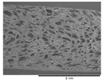
- FIG. 6 It is an enlarged sectional view of the microphone which contains the rubber foam which concerns on one Embodiment of this invention as an insulator, and is the sectional view of the sound collecting part of FIG. It is a perspective view of the insulator shown in FIG. 6 is a cross-sectional SEM photograph of the rubber foam sheet obtained in Example 1.
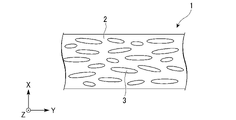
- FIG. 1 is a conceptual diagram of a rubber foam according to an embodiment of the present invention. As shown in FIG. 1, the rubber foam 1 has a rubber phase 2 and a pore portion 3 contained in the rubber phase 2.
- the rubber foam 1 is a plate-like body having a flatly crushed shape in the thickness direction (X direction).
- the rubber phase 2 contains butyl rubber and a thermoplastic resin. Butyl rubber is crosslinked. The thermoplastic resin is dispersed or compatible with the matrix of butyl rubber.
- the rubber phase 2 may contain components other than butyl rubber and the thermoplastic resin.
- the content of the butyl rubber and the thermoplastic resin in the rubber phase 2 may be, for example, in the range of 45% by mass or more and 80% by mass or less. The components other than the butyl rubber and the thermoplastic resin contained in the rubber phase 2 will be described later.
- the pore portion 3 has a shape that expands in the directions (Y direction and Z direction) along the surface of the rubber foam 1.
- the pores 3 may form continuous pores connected in a direction along the surface. Further, the pores 3 may be arranged in layers in the thickness direction (X direction) of the rubber foam 1, or may be partially communicated with each other. It is preferable that at least a part of the pores 3 (pores) is independent pores.
- the rubber foam 1 having independent pores has a reduced amount of air permeation as compared with the rubber foam 1 having only continuous pores. Therefore, by using the rubber foam 1 having independent pores as the surround member of the speaker, it is possible to suppress the change in the acoustic characteristics due to the air leaking from the back surface of the diaphragm from the speaker.
- the rubber foam 1 according to this embodiment is used as an acoustic member.
- the acoustic member include a surround member of a speaker.
- the surround member is provided between the diaphragm of the speaker and the speaker frame, and supports the diaphragm without hindering the front-back movement (vibration) of the diaphragm.
- vibration absorbers that absorb / eliminate unnecessary vibrations in musical instruments and acoustic devices can be mentioned.
- the vibration absorber include a microphone insulator that absorbs and eliminates vibration from the microphone housing to the sound collecting member (microphone capsule).
- the rubber foam 1 used as the acoustic member preferably has a storage elastic modulus of 7 MPa or more, and more preferably 9 MPa or more.
- the density is not particularly limited as long as it is smaller due to foaming than the non-foamed solid rubber, but is preferably 0.8 g / cm 3 or less, and more preferably 0.7 g / cm 3 or less.
- the relative density of the rubber foam 1 to the lithod rubber (density of the rubber foam 1 / density of the lithod rubber) is preferably 0.64 or less. Further, from the viewpoint of the strength of the rubber foam 1, the relative density of the rubber foam 1 with respect to the lithod rubber is preferably 0.40 or more.
- the rubber composition used as a raw material for the rubber foam contains butyl rubber (A) and a thermoplastic resin (B). Further, the rubber composition is a vulcanizing agent (D) that stabilizes the shape of the rubber foam 1 by vulcanizing a chemical foaming agent (C) for forming the pores 3 by foaming and butyl rubber (A). ) And.
- butyl rubber is known as a non-diene rubber.
- Butyl rubber is a synthetic rubber having a low degree of unsaturation in which a small amount of isoprene is copolymerized with isobutylene, and is a rubber material having excellent environmental resistance.
- Types include regular butyl rubber and halogenated butyl rubber. It is graded according to the degree of unsaturation and halogen content. As the halogenated butyl rubber, chlorinated butyl rubber and brominated butyl rubber are typical. Butyl rubber can be used alone in one type or grade, or in combination of multiple types or grades.
- thermoplastic resin any thermoplastic resin that can be uniformly mixed with the butyl rubber (uncrosslinked state) to be used can be used without particular limitation.
- a thermoplastic resin that is compatible with uncrosslinked butyl rubber is preferable. Therefore, a thermoplastic resin having no polar group is preferable, and a resin that does not affect the cross-linking of the butyl rubber, that is, has no unsaturated group such as a double bond is preferable.
- the melt softening temperature (melting point or glass transition temperature) is sufficiently higher than normal temperature, 40 ° C. or higher, preferably 60 ° C.
- melt softening temperature is foam vulcanization. It is preferably lower than the temperature, for example, 120 ° C. or lower.
- styrene-based resins and polyolefin-based resins are preferable.
- a polyolefin wax such as low molecular weight polyethylene may be added.
- Polyolefin-based resins and low-molecular-weight polyolefin waxes are mainly distinguished by their weight average molecular weight (Mw).
- Polyolefin-based resins with Mw of 50,000 or more are called polyolefin resins, and polyolefin waxes with Mw of less than 50,000 are called polyolefin waxes. Sometimes. Therefore, in a broad sense, all of them are included in the range of polyolefin-based resins.
- styrene-based resin examples include homopolymers of styrene and copolymers with monomers having no polar group.
- a styrene-based resin containing an isobutylene unit similar to that of butyl rubber has excellent compatibility with uncrosslinked butyl rubber.
- the polyolefin resin examples include polyethylene, polypropylene, and an ethylene-propylene copolymer. In particular, polyethylene and ethylene-propylene copolymers having a low melting point are preferable.
- the thermoplastic resin preferably has a melt flow rate of 1 to 100 g / 10 min (230 ° C./2.16 kg) or a melt viscosity of 10 to 10000 mPa ⁇ s (140 ° C.). Above all, it is more preferable that it is at least one that satisfies any of the following requirements 1 to 3. It is preferable that the thermoplastic resin satisfies the requirement 1, and it is particularly preferable that the thermoplastic resin satisfies the two requirements of the requirement 1 and the requirement 2, or the two requirements of the requirement 1 and the requirement 3.
- the melt softening temperature can be determined by DSC measurement or the like.
- Melt flow rate (MFR) can be measured by a method according to JIS K 7210 or ASTM D1238.
- the melt viscosity can be measured by a method according to JIS K 7199. In each case, the manufacturer catalog value can be referred to.
- thermoplastic resins preferably have the effect of lowering the viscosity of the composition at the molding temperature of the rubber foam, and include the foaming agent (including when combined with the optional softening agent (E) described later). It is preferable that the viscosity (Moony viscosity) of the rubber composition excluding the foaming aid (including the foaming aid) and the vulcanizing agent (including the vulcanizing aid) can be in the range of 10 to 60 [ML1 + 4, 100 ° C.].
- the blending amount of the thermoplastic resin in the rubber composition is 10 to 60 parts by mass, preferably 20 to 45 parts by mass with respect to 100 parts by mass of the butyl rubber (A).
- the amount of the thermoplastic resin is more than 60 parts by mass, the high loss coefficient due to butyl rubber is impaired, and it may not be suitable as an acoustic member. If the amount of the thermoplastic resin is less than 10 parts by mass, the effect of lowering the viscosity of the composition may be reduced.
- Chemical foaming agent a chemical foaming agent generally used for foam molding can be used.
- organic foaming agents can be preferably used.
- ADCA azodicarbosoamide
- azobisisobutylnitrile diazoaminobenzene and the like.
- examples thereof include sulfonyl hydrazide compounds such as azo compounds, benzenesulfonyl hydrazides and toluenesulfonyl hydrazides.
- foaming agents such as p-toluenesulfonyl azide, 4,4'-diphenylsulfonyl azide, and 4,4'-oxybisbenzososulfonyl hydrazide (OBSH) can also be mentioned. These may be used alone or in combination of two or more. Particularly preferred is the use of, for example, ADCA in terms of heating rise and the amount of gas generated by temperature. Further, when two or more kinds are used together, it is preferable to use, for example, ADCA and OBSH in combination from the viewpoint of adjusting the foaming decomposition temperature.
- the blending ratio of the foaming agent is preferably 1 to 20 parts by mass, more preferably 3 to 10 parts by mass with respect to 100 parts by mass of butyl rubber.
- Effervescence aids are used as appropriate to adjust the timing of effervescence.
- an optimum foaming aid may be appropriately combined according to the type of the chemical foaming agent.
- ADCA and its derivatives are used as the foaming agent, it is preferable to use urea as the foaming aid.
- the foaming aid can be used in an amount of 4 parts by mass to 22.5 parts by mass with respect to 10 parts by mass of the foaming agent.
- a heat-expandable microballoon or a physical foaming agent such as carbon dioxide gas (supercritical CO 2 ) can be used instead of the chemical foaming agent.
- the vulcanizing agent (including a vulcanization accelerator) is not particularly limited, and is, for example, a sulfur-based vulcanizing agent such as sulfur or tetraalkylthiraum-disulfide, a metal oxide, an organic peroxide, a resin vulcanizing agent, or the like. Can be mentioned. These may be used alone or in combination of two or more. In particular, it is preferable to contain a metal oxide together with sulfur.
- the metal oxide is not particularly limited, and examples thereof include zinc oxide and magnesium oxide, and zinc oxide is preferable.
- the blending amount of the vulcanizing agent is preferably 1 part by mass or more and 30 parts by mass or less, and more preferably 5 parts by mass or more and 15 parts by mass or less with respect to 100 parts by mass of butyl rubber.
- Softener It is preferable to add a softening agent to the composition of the present invention in order to appropriately adjust the viscosity of the composition at the time of foam molding.
- the softening agent include phthalic acid ester-based plasticizers such as dioctylphthalate and dibutylphthalate, polymer plasticizers having a molecular weight of 1000 to 8000 such as polyester plasticizers, and lubricating oils such as spindle oils, machine oils and cylinder oils.
- Paraffin-based process oils Paraffin-based process oils, process oils such as naphthen-based process oils, petroleum-based softeners such as paraffins such as liquid paraffin and vaseline, coal tar-based softeners such as coal tar and coal tar pitch, castor oil, cottonseed oil, etc.
- Examples thereof include aliphatic softeners, waxes such as beeswax and paraffin, resins that are liquid or solid at room temperature, and liquid polymers such as polybutene.
- vegetable oil vulcanized with sulfur such as factice can also be used.
- paraffinic process oil, liquid polymer and factice are more preferable. These can be used alone or in combination of two or more.
- the liquid polymer is also called a liquid polymer or a liquid rubber, and is a polymer that is liquid (including a semi-solid state) at room temperature.
- a liquid polymer or a liquid rubber There are various grades from low molecular weight to high molecular weight, but in the present invention, those having a weight average molecular weight (Mw) of 1,000 or more and 120,000 or less are used.
- Mw weight average molecular weight
- Mw weight average molecular weight
- the foam molded product for an acoustic member according to the present invention does not soften more than necessary, and a non-sticky product can be obtained.
- Mw is 120,000 or less
- the liquid polymer can be uniformly dispersed in the composition, and a homogeneous foam molded product can be obtained.
- the Mw of the liquid polymer is preferably 2,000 or more.
- the liquid polymer examples include polybutene, polyisobutylene, polyisoprene, polybutadiene and the like.
- the liquid polymer is preferably polyisobutylene having an isobutylene unit which is a constituent unit of butyl rubber.
- SP value solubility parameter
- the solubility parameter (SP value) can be adopted as an index at that time, and if it is within ⁇ 0.5 with respect to the SP value (7.3 to 8.1) of butyl rubber, it can be said that the compatibility is excellent.
- Polyisobutylene is also within this SP value range. Even if the SP value range is not satisfied by itself, it may be usable when the SP value range is satisfied by mixing. Therefore, the liquid polymer can be used alone or in combination of two or more.
- the weight average molecular weight (Mw) as the mixture is adopted as the molecular weight, but it is preferable to combine those having a similar Mw.
- the "SP value" in the present invention is a value as a Hildebrand parameter. As the SP value, a value published as a theoretical value can be adopted. It can also be obtained by a known calculation method. Furthermore, it can be actually measured by the dakuten titration method.
- the weight average molecular weight (Mw) is a standard polystyrene-equivalent value measured by gel permeation chromatography (GPC).
- the optimum blending ratio can be appropriately selected within a range satisfying the characteristics suitable for an acoustic member.
- the softening agent can be blended with respect to 100 parts by mass of butyl rubber, preferably 1 to 100 parts by mass, more preferably 10 to 60 parts by mass.
- additives known in the art such as fillers and processing aids can be appropriately added to the rubber foam 1 according to the present embodiment as long as the effects of the present invention are not impaired.
- other rubber (elastomer) components and resin components may be added as long as the effects of the present invention are not impaired.
- the hardness of the rubber foam 1 can be increased by adding a filler.
- the filler is not particularly limited, and examples thereof include carbon black, silica, calcium carbonate, talc, clay, and titanium white. These may be used alone or may be a mixture of two or more. In particular, it may be preferable to add carbon black in terms of adjusting the color of the diaphragm when applied to a speaker or the like.
- the blending amount of carbon black is preferably in the range of 10 to 100 parts by mass, more preferably in the range of 50 to 100 parts by mass, and in the range of 50 to 90 parts by mass with respect to 100 parts by mass of butyl rubber. It is more preferable to have. Further, the blending amount of carbon black with respect to 100 parts by mass of butyl rubber may be in the range of 10 to 70 parts by mass, or may be in the range of 30 to 50 parts by mass.
- the processing aid is not particularly limited as long as it is a material that improves processability, and examples thereof include compounds having a fatty acid skeleton such as stearic acid and amines. These may be used alone, or two or more kinds may be mixed and used.
- the rubber foam 1 of the present embodiment having the above configuration has the rubber phase 2 and the pores 3 contained in the rubber phase 2, the weight is reduced as compared with the lithod rubber. .. Further, since the rubber phase 2 contains butyl rubber, the loss coefficient is high. Further, since the rubber phase 2 contains butyl rubber, the loss coefficient becomes higher. Further, since the butyl rubber contained in the rubber phase 2 is crosslinked and the thermoplastic resin is dispersed or compatible with the matrix of the butyl rubber, the storage elastic modulus of the rubber foam 1 is improved. Therefore, the rubber foam 1 is useful as an acoustic member.
- the method for producing a rubber foam includes a step of preparing a rubber composition and a step of foam cross-linking.
- Step of preparing rubber composition In the step of preparing the rubber composition, the rubber composition which is the raw material of the rubber foam is prepared.
- the rubber composition is preferably prepared by kneading the raw materials in two stages of a first kneading step and a second kneading step.
- the thermoplasticity of the butyl rubber (A) and the thermoplastic resin (B) is such that the amount of the thermoplastic resin (B) is 10 to 60 parts by mass with respect to 100 parts by mass of the butyl rubber (A).
- the base rubber composition is obtained by heating and kneading at a temperature higher than the temperature at which the resin (B) melts.
- a material other than the cross-linking component and the foaming component such as a softener and a filler, may be blended together with the raw material rubber (butyl rubber) and the thermoplastic resin.
- This first kneading step is also called an A kneading step.
- the base rubber composition obtained in this first kneading step is a composition containing a material constituting the rubber foam, and is a vulcanization component for cross-linking the raw rubber and a foaming component for foaming the rubber composition. It is a composition which does not contain.
- the viscosity of the base rubber composition is preferably adjusted to the Mooney viscosity range of about 10 to 60 [ML1 + 4, 100 ° C.].
- the base rubber composition preferably has a low viscosity in order to increase the foaming ratio in the foaming crosslinking step described later.
- the first kneading step (A kneading step) does not contain a vulcanizing component or a foaming component
- kneading can be carried out by heating to some extent or kneading with heat generation, for example, by increasing the shearing force.
- the heating temperature or heat generation temperature in the first kneading step is preferably + 1 ° C. or higher with respect to the melt softening temperature of the thermoplastic resin. This gives a uniform base rubber composition.
- the Mooney viscosity of the obtained rubber composition for foam cross-linking is preferably in the range of 10 to 60 [ML1 + 4, 100 ° C.].
- a kneading method in which the temperature does not rise is selected and used. For example, an open roll or a kneader with a cooling mechanism can be used.
- Foam cross-linking process In foam crosslinking, a rubber composition for foam crosslinking (rubber compound) is heated and pressed to foam a chemical foaming agent (C), and butyl rubber (A) is crosslinked with a vulcanizing agent (D) to form a rubber foam. (Acoustic member) is obtained.
- the rubber composition for foam cross-linking (rubber compound) is formed into a sheet shape (thickness 1 to 10 mm) or a film shape (thickness 0.1 to 1 mm).
- the obtained molded product may be placed in a molding die having a predetermined shape and heated and pressurized under appropriate heating and pressurizing conditions.
- the molded product molded into the sheet or film shape may be punched into a predetermined shape, and then the obtained punched product may be heated and pressed in a molding die.
- a predetermined amount of the rubber composition for foam cross-linking (rubber compound) may be directly placed in a molding die having a predetermined shape and heated and pressed.
- the heating and pressurizing conditions in the molding die are appropriately set depending on the type and blending ratio of each component constituting the foam cross-linking rubber composition (rubber compound), and the heating temperature is, for example, 130 to 200. It is preferable to set the temperature and pressure to 0.5 to 100 MPa and the heating and pressurizing time to be 0.02 to 60 minutes.
- the thermoplastic resin added to the butyl rubber crosslinked product as the matrix is dispersed, or the dispersed state cannot be confirmed. Therefore, in the present specification, "compatible” means not only the case where they are completely mixed at the molecular level, but also all the cases where the dispersed state (incompatible) cannot be confirmed. Specifically, the film state is maintained even if a non-foamed film or an additive-free film such as a filler is pulled by hand, and if the dispersion cannot be visually confirmed, it can be regarded as a compatible state.
- the thermoplastic resin (B) is heated and kneaded at a temperature higher than the melting temperature in the first kneading step, so that the base rubber composition has a uniform composition. You can get things. Further, in the second kneading step, the thermoplastic resin (B) is kneaded at a low temperature equal to or lower than the melting temperature, so that the chemical foaming agent (C) and the vulcanizing agent (D) are reacted with the thermoplastic resin (B). It can be kneaded without kneading, and a rubber composition for foam cross-linking having a uniform composition can be obtained.
- the rubber composition for foam cross-linking is heated and pressurized, so that a rubber foam in which the butyl rubber is uniformly cross-linked and the thermoplastic resin is dispersed or compatible with the butyl rubber matrix can be obtained. ..
- the gas generated by the foaming agent tends to diffuse in the direction perpendicular to the pressurizing direction. Therefore, the obtained rubber foam has a shape in which the pores contained in the rubber phase expand in the direction along the surface (pressurized surface) of the rubber foam, and follows the surface of the pores. It becomes easy to form continuous pores connected in the direction.
- the annular vibration absorber of the present embodiment includes the rubber foam of the present embodiment described above.
- the annular vibration absorber is made by molding a rubber foam into an annular shape.
- the annular vibration absorber may be formed only from the rubber foam of the present embodiment.
- the annular vibration absorber may be an annular shape, an elliptical ring shape, or a polygonal annular shape having a plurality of corners.
- the annular vibration absorber can be used, for example, as a surround member for a speaker or an insulator for a microphone. Examples of the surround member (edge member) of the speaker include a corrugation edge, a roll edge, a flat edge, an accordion edge, and a gathered edge.
- the annular vibration absorber can be produced, for example, by placing the above-mentioned rubber composition for foam cross-linking in a molding die having a predetermined shape and heating and pressurizing it.
- FIG. 2 is a front view of a speaker including a rubber foam according to an embodiment of the present invention as a surround member.
- 3 is a sectional view taken along line III-III of FIG. 2
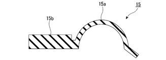
- FIG. 4 is an enlarged sectional view of the surround member shown in FIG.
- the speaker 10 shown in FIGS. 2 to 4 includes a diaphragm 11, a coil 12, and a magnetic circuit 13 attached to a speaker frame 14.
- the diaphragm 11 is attached to the speaker frame 14 by a surround member 15 formed of the rubber foam described above.
- the surround member 15 has a ring shape, as is understood in the art.
- the surround member 15 is attached to the diaphragm 11 by any suitable type of glue, paste, adhesive or fastener, or any suitable method understood in the art. It has one end and a second end attached to the speaker frame 14.
- the coil 12 may be referred to as a voice coil and may be attached to the speaker frame 14 by a flexible suspension 16.
- the flexible suspension 16 is commonly referred to as a "spider" and is made of a flexible material such as corrugated fabric or any suitable method understood in the art.
- the coil 12 has a wire winding (not shown) wound around an outer portion of the coil, similar to a conventional coil, and is connected to, for example, a terminal board (not shown) as understood in the art. Has been done.
- the magnetic circuit 13 is attached to the speaker frame 14 by any suitable type of attachment structure understood in the art.
- a center cap 17 is attached to the center of the diaphragm 11.
- the surround member 15 may have a significantly different wall thickness between the first end portion 15a connected to the diaphragm 11 and the second end portion 15b fixed to the speaker frame 14.
- the second end portion 15b may be formed into a thick portion having a thickness of about 2 mm
- the first end portion 15a may be formed into a thin portion having a thickness of about 0.4 to 0.5 mm.
- the size (thickness, length, etc.) of the surround member 15 is not particularly limited, and the surround member 15 can be appropriately formed into an optimum size according to the size of the speaker and the output power.
- the surround member 15 contains a rubber foam.
- the surround member 15 may be composed of only the rubber foam.
- the surround member 15 may have a structure in which the surface thereof has a dense surface called a skin layer and a rubber foam layer containing foamed pores (cells) inside the surround member 15.
- the diaphragm 11 is supported by the speaker frame 14, and the surround member 15 having a high loss coefficient sufficiently attenuates the excess vibration of the diaphragm 11, so that the acoustic characteristics are improved.
- FIG. 5 is a front view of a microphone containing a rubber foam according to an embodiment of the present invention as an insulator.
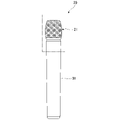
- 6 is a cross-sectional view of the sound collecting portion of FIG. 5
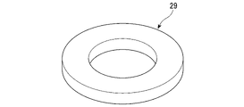
- FIG. 7 is a perspective view of the insulator shown in FIG.
- the microphone 20 shown in FIGS. 5 to 7 has a sound collecting unit 21 and a housing unit 31.
- the sound collecting unit 21 includes a sound collecting unit carver 22, a windshield 23 to which the inside of the sound collecting unit carver 22 is attached, a diaphragm 24 arranged inside the windshield 23, a voice coil 25, a yoke 26 with a magnet, and a microphone. It has a capsule (microphone cartridge) 27, a microphone capsule case 28, an insulator 29, and a microphone body 30.
- the insulator 29 has an annular shape.
- the insulator 29 is arranged between the microphone capsule 27 and the microphone body 30.
- the insulator 29 absorbs and eliminates the vibration generated in the housing portion 31.
- the insulator 29 contains a rubber foam.
- the insulator 29 may be composed of only the rubber foam.
- the insulator 29 may have a structure in which the surface thereof has a dense surface called a skin layer and a rubber foam layer containing foamed pores (cells) inside the insulator 29.
- the shape of the insulator 29 is not limited to a simple annular shape, but may be appropriately changed according to the shapes of the microphone capsule 27 and the microphone body 30.
- the insulator 29 may be lightened for weight reduction.
- the microphone capsule 27 is supported by the insulator 29, and the vibration generated in the housing portion 31 is attenuated by the insulator 29, so that noise is less likely to enter and the acoustic characteristics are improved.
- Example 1 ⁇ 1st kneading process (A kneading process)>
- TMTD Tetramethylthiumum disulfide
- MBT 2-mercaptobenzothiazole
- MBT 2-mercaptobenzothiazole
- the rubber composition for foam cross-linking obtained in the second kneading step was formed into a sheet having a thickness of 2 mm by hot-cooling press molding.
- the obtained sheet-shaped rubber composition for foaming and cross-linking was placed in a mold and heated at a foaming vulcanization temperature (160 ° C.) for 30 minutes while pressurizing to prepare a rubber foam sheet.
- the Mooney viscosity of the base rubber composition and the rubber composition for foam cross-linking, the density and relative density of the rubber foam sheet, and the storage elastic modulus E'as the viscoelastic property were measured. The measurement results are shown in Table 1 below. The measurement conditions and evaluation of each physical property are as follows.
- the Mooney viscosity at 100 ° C. was measured using a rubber vulcanization tester (Curebase) manufactured by M & K Co., Ltd. in accordance with JIS K 6300.
- Examples 2 to 3 Comparative Examples 1 to 2
- a rubber sheet was formed by performing a first kneading step, a second kneading step, and a foam cross-linking step in the same manner as in Example 1 except that the composition was changed to the composition shown in Table 1.
- the evaluation results of the physical properties are shown in Table 1.
- the rubber foam sheets obtained in Examples 1 to 3 to which the thermoplastic resin was added have a higher storage elastic modulus than the rubber foam sheets obtained in Comparative Examples 1 and 2 to which the thermoplastic resin was not added.
- the base rubber composition obtained in the first kneading step and the rubber composition for foam crosslinking obtained in the second kneading step were used. It was possible to obtain a rubber foam sheet having an excellent Mooney viscosity, a good skin condition, and an excellent storage elastic modulus.
- the rubber foam sheet obtained in Example 1 was cut in the thickness direction, and the cross section thereof was observed using an SEM (scanning electron microscope). The result is shown in FIG. From the SEM photograph of FIG. 8, the rubber foam sheet obtained in Example 1 has pores expanding in the direction along the surface, and continuous pores in which some of the pores are connected in the direction along the surface are formed. It can be seen that it is formed.
- the rubber foam of the present embodiment is useful as an acoustic member because it is lightweight, has a high loss coefficient, and has an excellent storage elastic modulus. Since the speaker and the microphone using the annular vibration absorber containing the rubber foam of the present embodiment attenuates excess vibration, the acoustic characteristics are improved.
Landscapes
- Chemical & Material Sciences (AREA)
- Engineering & Computer Science (AREA)
- Materials Engineering (AREA)
- Health & Medical Sciences (AREA)
- Chemical Kinetics & Catalysis (AREA)
- Medicinal Chemistry (AREA)
- Polymers & Plastics (AREA)
- Organic Chemistry (AREA)
- Multimedia (AREA)
- Physics & Mathematics (AREA)
- Acoustics & Sound (AREA)
- Signal Processing (AREA)
- Manufacture Of Porous Articles, And Recovery And Treatment Of Waste Products (AREA)
- Diaphragms For Electromechanical Transducers (AREA)
Abstract
このゴム発泡体は、音響部材用のゴム発泡体であって、ブチルゴムと、熱可塑性樹脂とを含むゴム相と、該ゴム相層に内包される空孔部とを有し、前記ゴム相層は、前記ブチルゴムが架橋されており、前記ブチルゴムのマトリックス中に前記熱可塑性樹脂が分散或いは相溶していることを特徴とする。
Description
本発明は、音響部材用ゴム発泡体、環状振動吸収材、スピーカー、マイク、及び、ゴム発泡体の製造方法に関する。
本願は、2020年12月7日に、日本に出願された特願2020-202822号に基づき優先権を主張し、その内容をここに援用する。
本願は、2020年12月7日に、日本に出願された特願2020-202822号に基づき優先権を主張し、その内容をここに援用する。
スピーカーの振動板の外周端部を支えるエッジ部材(サラウンド部材ともいう)など、振動板の余分な振動を吸収して発生させる音質を向上させる部材には、各種ゴムの弾性材料が使用されている。
振動板の余分な振動を効果的に吸収し、音響特性に優れた材料を提供するために、損失係数の高い材料を軽量化することが提案されている。
特許文献1にはゴム、軟化剤、有機発泡剤、加硫剤を含有する粘性ゴム混和物を加硫発泡した粘弾性発泡体からなるスピーカー用部材(エッジ部材)が開示されており、その粘弾性発泡体の引張強度が0.1~100kg/cm2、比重が0.07~1.2の範囲に設定されている。
一方で損失係数の高い材料として非ジエン系のブチルゴム(イソブチレン-イソプレンゴム(IIR)ともいう)がある。特許文献1における粘弾性発泡体のゴム材料としてブチルゴム(IIR)も例示されているものの、実施例にはスチレン-ブタジエンゴム(SBR)、アクリロニトリル-ブタジエンゴム(NBR)及びエチレン-プロピレン-ターポリマーゴム(EPT)などの発泡ゴムとしてよく知られたゴム材料の発泡体が示されている。しかしながら、ブチルゴムの加硫発泡した発泡体は製造されておらず、その他、従来技術を見てもほとんど知られていない。
材料の軽量化という点では、特許文献1のように発泡体(発泡ゴム)を使用するという選択肢がある。しかしながら、損失係数の高い非ジエン系のブチルゴムを発泡すると、その硬さ(貯蔵弾性率)が著しく低下する現象が見られた。その結果、ソリッドゴムを使用した場合のような音質の向上が維持できず、音響部材としての特性が損なわれることを本発明者らは見出した。
そこで、本発明は、ブチルゴムをベースとして、音響部材に適した軽量なゴム発泡体と、そのゴム発泡体を用いた環状振動吸収材、スピーカー、マイク、及び、そのゴム発泡体の製造方法を提供することを目的とする。
本発明者ら上記課題を解決するため、鋭意検討した結果、ブチルゴムに熱可塑性樹脂を配合することで適度に高い発泡倍率であるにも拘わらず、硬度(弾性率)の低下が抑えられたゴム発泡体が得られることを見出した。ここで、ブチルゴムはゴム相のマトリックス(連続相)を構成し、熱可塑性樹脂はこのマトリックス中に分散しているか相溶している。
すなわち、本発明の一態様は、音響部材用のゴム発泡体であって、ブチルゴムと、熱可塑性樹脂とを含むゴム相と、該ゴム相に内包される空孔部とを有し、前記ゴム相は、前記ブチルゴムが架橋されており、前記ブチルゴムのマトリックス中に前記熱可塑性樹脂が分散或いは相溶していることを特徴とするゴム発泡体である。
又、本発明の他の態様は、上記のゴム発泡体を含む環状振動吸収材である。
又、本発明の他の態様は、上記のゴム発泡体を介して、振動板がスピーカーフレームに支持されているスピーカーである。
又、本発明の他の態様は、上記のゴム発泡体を介して、マイクカプセルがマイクボディに支持されているマイクである。
又、本発明の他の態様は、下記の工程を含むゴム発泡体の製造方法である。
ブチルゴム(A)と、下記の要件のいずれかを満たす1種以上の熱可塑性樹脂(B)とを、前記ブチルゴム(A)100質量部に対する前記熱可塑性樹脂(B)の量が10~60質量部となる割合で、前記熱可塑性樹脂(B)が溶融する温度以上で加熱混練して、ベースゴム組成物を得る工程と、
(要件1):溶融軟化温度が40℃以上120℃以下
(要件2):メルトフローレイトが5~70g/10min(230℃/2.16kg)
(要件3):溶融粘度が50~2000mPa・s(140℃)
前記ベースゴム組成物と、化学発泡剤(C)と、加硫剤(D)とを、前記化学発泡剤(C)の発泡温度よりも低い温度で混練して発泡架橋用ゴム組成物を得る工程、及び
前記発泡架橋用ゴム組成物を加熱加圧して、前記化学発泡剤(C)を発泡させるとともに、前記ブチルゴム(A)を前記加硫剤(D)で架橋させる工程。
ブチルゴム(A)と、下記の要件のいずれかを満たす1種以上の熱可塑性樹脂(B)とを、前記ブチルゴム(A)100質量部に対する前記熱可塑性樹脂(B)の量が10~60質量部となる割合で、前記熱可塑性樹脂(B)が溶融する温度以上で加熱混練して、ベースゴム組成物を得る工程と、
(要件1):溶融軟化温度が40℃以上120℃以下
(要件2):メルトフローレイトが5~70g/10min(230℃/2.16kg)
(要件3):溶融粘度が50~2000mPa・s(140℃)
前記ベースゴム組成物と、化学発泡剤(C)と、加硫剤(D)とを、前記化学発泡剤(C)の発泡温度よりも低い温度で混練して発泡架橋用ゴム組成物を得る工程、及び
前記発泡架橋用ゴム組成物を加熱加圧して、前記化学発泡剤(C)を発泡させるとともに、前記ブチルゴム(A)を前記加硫剤(D)で架橋させる工程。
本発明によれば、ブチルゴムと相溶する熱可塑性樹脂を添加することで、発泡による軽量化と共に、弾性率の低下を抑制して、音響部材に適したゴム発泡体を提供することができる。また、本発明によれば、音響特性に優れた環状振動吸収材、スピーカーを提供することができる。更に、本発明によれば、音響部材に適したゴム発泡体の製造方法を提供することができる。
以下、本発明の実施形態を、図面を参照しながら説明する。
[ゴム発泡体]
本発明に係るゴム発泡体について説明する。
図1は、本発明の一実施形態に係るゴム発泡体の概念図である。
図1に示すように、ゴム発泡体1は、ゴム相2と、ゴム相2に内包される空孔部3とを有する。ゴム発泡体1は、厚さ方向(X方向)に、偏平に潰れた形状を有する板状体とされている。
本発明に係るゴム発泡体について説明する。
図1は、本発明の一実施形態に係るゴム発泡体の概念図である。
図1に示すように、ゴム発泡体1は、ゴム相2と、ゴム相2に内包される空孔部3とを有する。ゴム発泡体1は、厚さ方向(X方向)に、偏平に潰れた形状を有する板状体とされている。
ゴム相2は、ブチルゴムと熱可塑性樹脂とを含む。ブチルゴムは架橋されている。熱可塑性樹脂は、ブチルゴムのマトリックス中に分散或いは相溶している。ゴム相2は、ブチルゴムと熱可塑性樹脂以外の成分を含んでいてもよい。ゴム相2中のブチルゴムと熱可塑性樹脂の含有量は、例えば、45質量%以上80質量%以下の範囲にあってもよい。ゴム相2に含まれるブチルゴムと熱可塑性樹脂以外の成分は後述する。
空孔部3は、ゴム発泡体1の表面に沿った方向(Y方向とZ方向)に拡がった形状を有する。空孔部3は、表面に沿った方向に連結した連続気孔を形成していてもよい。また、空孔部3は、ゴム発泡体1の厚さ方向(X方向)では層状に配列していてもよく、一部が連通していてもよい。
空孔部3(気孔)の少なくとも一部は、独立気孔であることが好ましい。独立気孔を有するゴム発泡体1は、連続気孔のみからなるものと比較して、空気の透過量が低減する。このため、独立気孔を有するゴム発泡体1を、スピーカーのサラウンド部材として用いることによって、振動板背面の空気がスピーカーから漏れ出ることによる音響特性の変化を抑制することができる。
空孔部3(気孔)の少なくとも一部は、独立気孔であることが好ましい。独立気孔を有するゴム発泡体1は、連続気孔のみからなるものと比較して、空気の透過量が低減する。このため、独立気孔を有するゴム発泡体1を、スピーカーのサラウンド部材として用いることによって、振動板背面の空気がスピーカーから漏れ出ることによる音響特性の変化を抑制することができる。
本実施形態に係るゴム発泡体1は、音響部材として使用される。音響部材としては、スピーカーのサラウンド部材が挙げられる。サラウンド部材とは、スピーカーの振動板とスピーカーフレームとの間に設けられ、振動板の前後の移動(振動)を妨げずに、振動板を支持するものである。この他には、楽器や音響装置において不要な振動を吸収/排除する振動吸収材を挙げられる。振動吸収材としては、例えば、マイクの筐体から集音部材(マイクカプセル)への振動を吸収排除するマイクインシュレータなどが挙げられる。
音響部材として使用されるゴム発泡体1としては、貯蔵弾性率が7MPa以上であることが好しく、9MPa以上であることがより好ましい。また、密度は発泡させていないソリッドゴムよりも発泡により小さくなっていれば特に制限されないが、0.8g/cm3以下が好ましく、0.7g/cm3以下がより好ましい。リソッドゴムに対するゴム発泡体1の相対密度(ゴム発泡体1の密度/リソッドゴムの密度)は、0.64以下であることが好ましい。また、ゴム発泡体1の強度の観点から、リソッドゴムに対するゴム発泡体1の相対密度は、0.40以上であることが好ましい。
ゴム発泡体の原料となるゴム組成物は、ブチルゴム(A)と、熱可塑性樹脂(B)とを含む。また、ゴム組成物は、発泡によって空孔部3を形成するための化学発泡剤(C)と、ブチルゴム(A)を加硫させてゴム発泡体1の形状を安定化させる加硫剤(D)とを含む。
(ブチルゴム)
ブチルゴムは、非ジエン系のゴムとして知られている。ブチルゴムはイソブチレンに少量のイソプレンが共重合した不飽和度の低い合成ゴムであり、環境耐性に優れたゴム材料である。種類としてはレギュラーブチルゴムとハロゲン化ブチルゴムがある。不飽和度やハロゲン含量によってグレード分けされている。ハロゲン化ブチルゴムとしては塩素化ブチルゴム及び臭素化ブチルゴムが典型的である。
ブチルゴムは、一つの種類またはグレードを単独で、あるいは複数の種類またはグレードを組み合わせて使用することができる。
ブチルゴムは、非ジエン系のゴムとして知られている。ブチルゴムはイソブチレンに少量のイソプレンが共重合した不飽和度の低い合成ゴムであり、環境耐性に優れたゴム材料である。種類としてはレギュラーブチルゴムとハロゲン化ブチルゴムがある。不飽和度やハロゲン含量によってグレード分けされている。ハロゲン化ブチルゴムとしては塩素化ブチルゴム及び臭素化ブチルゴムが典型的である。
ブチルゴムは、一つの種類またはグレードを単独で、あるいは複数の種類またはグレードを組み合わせて使用することができる。
(熱可塑性樹脂)
熱可塑性樹脂としては、使用するブチルゴム(未架橋状態)と均一に混合し得る熱可塑性樹脂であれば特に制限無く使用することができる。特に未架橋ブチルゴムに相溶し得る熱可塑性樹脂が好ましい。このため、極性基を有さない熱可塑性樹脂が好ましく、また、ブチルゴムの架橋に影響しない、すなわち二重結合などの不飽和基を有さないものが好ましい。更にブチルゴムの混練温度で配合できるように、溶融軟化温度(融点乃至はガラス転移温度)が常温よりも十分高く、40℃以上、好ましくは60℃以上であり、一方、溶融軟化温度が発泡加硫温度よりも低い、例えば、120℃以下であることが好ましい。中でもスチレン系樹脂やポリオレフィン系樹脂が好ましい。また、これらの樹脂とブチルゴムの相溶性を向上させるために、低分子量ポリエチレンなどのポリオレフィンワックスを添加してもよい。ポリオレフィン系樹脂と低分子量のポリオレフィンワックスとは主にその重量平均分子量(Mw)によって区別され、Mwが5万以上のものをポリオレフィン系樹脂と呼び、Mwが5万未満のものをポリオレフィンワックスと呼ぶことがある。したがって、広義にはいずれもポリオレフィン系樹脂の範囲に含まれるものとする。
熱可塑性樹脂としては、使用するブチルゴム(未架橋状態)と均一に混合し得る熱可塑性樹脂であれば特に制限無く使用することができる。特に未架橋ブチルゴムに相溶し得る熱可塑性樹脂が好ましい。このため、極性基を有さない熱可塑性樹脂が好ましく、また、ブチルゴムの架橋に影響しない、すなわち二重結合などの不飽和基を有さないものが好ましい。更にブチルゴムの混練温度で配合できるように、溶融軟化温度(融点乃至はガラス転移温度)が常温よりも十分高く、40℃以上、好ましくは60℃以上であり、一方、溶融軟化温度が発泡加硫温度よりも低い、例えば、120℃以下であることが好ましい。中でもスチレン系樹脂やポリオレフィン系樹脂が好ましい。また、これらの樹脂とブチルゴムの相溶性を向上させるために、低分子量ポリエチレンなどのポリオレフィンワックスを添加してもよい。ポリオレフィン系樹脂と低分子量のポリオレフィンワックスとは主にその重量平均分子量(Mw)によって区別され、Mwが5万以上のものをポリオレフィン系樹脂と呼び、Mwが5万未満のものをポリオレフィンワックスと呼ぶことがある。したがって、広義にはいずれもポリオレフィン系樹脂の範囲に含まれるものとする。
スチレン系樹脂としては、スチレンの単独重合体や、極性基を有さないモノマーとの共重合体が挙げられる。特に、ブチルゴムと同様のイソブチレン単位を含むスチレン系樹脂は、未架橋のブチルゴムとの相溶性に優れる。
ポリオレフィン系樹脂としては、ポリエチレン、ポリプロピレン、エチレン-プロピレン共重合体などが挙げられる。特に、低融点を示すポリエチレン及びエチレン-プロピレン共重合体が好ましい。
ポリオレフィン系樹脂としては、ポリエチレン、ポリプロピレン、エチレン-プロピレン共重合体などが挙げられる。特に、低融点を示すポリエチレン及びエチレン-プロピレン共重合体が好ましい。
熱可塑性樹脂としては、メルトフローレイトが1~100g/10min(230℃/2.16kg)あるいは溶融粘度10~10000mPa・s(140℃)のものが好ましい。中でも、以下の要件1~3のいずれかを満たす少なくとも1種であることがより好ましい。熱可塑性樹脂は要件1を満足することが好ましく、要件1と要件2の2つの要件、もしくは要件1と要件3の2つの要件を満足することが特に好ましい。
(要件1):溶融軟化温度が40℃以上120℃以下
(要件2):メルトフローレイトが5~70g/10min(230℃/2.16kg)
(要件3):溶融粘度が50~2000mPa・s(140℃)
溶融軟化温度は、DSC測定などにより求めることができる。メルトフローレイト(MFR)は、JIS K 7210又はASTM D1238に準拠した方法で測定できる。溶融粘度はJIS K 7199に準拠した方法で測定できる。いずれも、メーカーカタログ値を参照することができる。
(要件1):溶融軟化温度が40℃以上120℃以下
(要件2):メルトフローレイトが5~70g/10min(230℃/2.16kg)
(要件3):溶融粘度が50~2000mPa・s(140℃)
溶融軟化温度は、DSC測定などにより求めることができる。メルトフローレイト(MFR)は、JIS K 7210又はASTM D1238に準拠した方法で測定できる。溶融粘度はJIS K 7199に準拠した方法で測定できる。いずれも、メーカーカタログ値を参照することができる。
これらの熱可塑性樹脂は、ゴム発泡体の成形温度において組成物粘度を引き下げる効果を有していることが好ましく、後述する任意添加の軟化剤(E)と組み合わせた場合も含めて、発泡剤(発泡助剤を含む)と加硫剤(加硫助剤を含む)を除くゴム組成物の粘度(ムーニー粘度)を10~60[ML1+4、100℃]の範囲内とできるものが好ましい。
ゴム組成物における熱可塑性樹脂の配合量は、ブチルゴム(A)100質量部に対して10~60質量部であり、好ましくは20~45質量部である。熱可塑性樹脂の量が60質量部より多くなりすぎると、ブチルゴムによる高い損失係数が損なわれ、音響部材として適さない場合がある。熱可塑性樹脂の量が10質量部よりも少なくなると、組成物粘度を引き下げる効果が低下する場合がある。
ゴム組成物における熱可塑性樹脂の配合量は、ブチルゴム(A)100質量部に対して10~60質量部であり、好ましくは20~45質量部である。熱可塑性樹脂の量が60質量部より多くなりすぎると、ブチルゴムによる高い損失係数が損なわれ、音響部材として適さない場合がある。熱可塑性樹脂の量が10質量部よりも少なくなると、組成物粘度を引き下げる効果が低下する場合がある。
(化学発泡剤)
化学発泡剤としては、一般的に発泡成形に用いられる化学発泡剤が使用できる。具体的には以下の如き有機発泡剤が好ましく使用できる。N,N’-ジニトロソペンタメチレンテトラミン、N,N’-ジメチル-N,N’-ジニトロソテレフタルアミド等のニトロソ化合物、アゾジカルボソアミド(ADCA)、アゾビスイソブチルニトリル、ジアゾアミノベンゼン等のアゾ化合物、ベンゼンスルホニルヒドラジド、トルエンスルホニルヒドラジド等のスルホニルヒドラジド化合物が挙げられる。また、その他p-トルエンスルホニルアジド、4,4’-ジフェニルスルホニルアジド、4,4’-オキシビスベンゾソスルホニルヒドラジド(OBSH)等の公知の発泡剤も挙げられる。これらは単独でもしくは2種以上併せて用いられる。特に好ましいのは、加熱上昇,温度によるガス発生量の点から例えばADCAを用いることである。さらに、2種以上併せて用いる場合は、発泡分解温度の調整の点から、例えばADCAおよびOBSHを併用することが好ましい。そして、上記発泡剤の配合割合は、ブチルゴム100質量部に対して好ましくは1~20質量部、より好ましくは3~10質量部である。
化学発泡剤としては、一般的に発泡成形に用いられる化学発泡剤が使用できる。具体的には以下の如き有機発泡剤が好ましく使用できる。N,N’-ジニトロソペンタメチレンテトラミン、N,N’-ジメチル-N,N’-ジニトロソテレフタルアミド等のニトロソ化合物、アゾジカルボソアミド(ADCA)、アゾビスイソブチルニトリル、ジアゾアミノベンゼン等のアゾ化合物、ベンゼンスルホニルヒドラジド、トルエンスルホニルヒドラジド等のスルホニルヒドラジド化合物が挙げられる。また、その他p-トルエンスルホニルアジド、4,4’-ジフェニルスルホニルアジド、4,4’-オキシビスベンゾソスルホニルヒドラジド(OBSH)等の公知の発泡剤も挙げられる。これらは単独でもしくは2種以上併せて用いられる。特に好ましいのは、加熱上昇,温度によるガス発生量の点から例えばADCAを用いることである。さらに、2種以上併せて用いる場合は、発泡分解温度の調整の点から、例えばADCAおよびOBSHを併用することが好ましい。そして、上記発泡剤の配合割合は、ブチルゴム100質量部に対して好ましくは1~20質量部、より好ましくは3~10質量部である。
(発泡助剤)
発泡助剤は発泡のタイミングを調整するために適宜使用される。発泡助剤としては化学発泡剤の種類に合わせて適宜最適な発泡助剤を組み合わせればよい。特に発泡剤としてADCA及びその誘導体を用いる場合には、発泡助剤として尿素を用いることが好ましい。発泡助剤は、発泡剤10質量部に対して4質量部~22.5質量部用いることができる。
なお、本発明のゴム発泡体を得るために、化学発泡剤に代えて、熱膨張性マイクロバルーン、もしくは炭酸ガス(超臨界CO2)などの物理発泡剤を用いることもできる。
発泡助剤は発泡のタイミングを調整するために適宜使用される。発泡助剤としては化学発泡剤の種類に合わせて適宜最適な発泡助剤を組み合わせればよい。特に発泡剤としてADCA及びその誘導体を用いる場合には、発泡助剤として尿素を用いることが好ましい。発泡助剤は、発泡剤10質量部に対して4質量部~22.5質量部用いることができる。
なお、本発明のゴム発泡体を得るために、化学発泡剤に代えて、熱膨張性マイクロバルーン、もしくは炭酸ガス(超臨界CO2)などの物理発泡剤を用いることもできる。
(加硫剤)
加硫剤(加硫促進剤を含む)は、特に限定されず、例えば、硫黄、テトラアルキルチラウム-ジスルフィドなどの硫黄系加硫剤、金属酸化物、有機過酸化物、樹脂加硫剤などが挙げられる。これらは単独で用いてもよく、2種以上を混合して用いてもよい。特に硫黄と共に金属酸化物を含んでいることが好ましい。金属酸化物は、特に限定されず、例えば酸化亜鉛、酸化マグネシウムなどが挙げられ、酸化亜鉛であることが好ましい。
加硫剤の配合量は、ブチルゴム100質量部に対して、1質量部以上30質量部以下であることが好ましく、5質量部以上15質量部以下であることがより好ましい。
加硫剤(加硫促進剤を含む)は、特に限定されず、例えば、硫黄、テトラアルキルチラウム-ジスルフィドなどの硫黄系加硫剤、金属酸化物、有機過酸化物、樹脂加硫剤などが挙げられる。これらは単独で用いてもよく、2種以上を混合して用いてもよい。特に硫黄と共に金属酸化物を含んでいることが好ましい。金属酸化物は、特に限定されず、例えば酸化亜鉛、酸化マグネシウムなどが挙げられ、酸化亜鉛であることが好ましい。
加硫剤の配合量は、ブチルゴム100質量部に対して、1質量部以上30質量部以下であることが好ましく、5質量部以上15質量部以下であることがより好ましい。
(軟化剤)
本発明の組成物には、発泡成形時の組成物の粘度を適宜調整するために軟化剤を添加することが好ましい。軟化剤としては、ジオクチルフタレート、ジブチルフタレート等のフタル酸エステル系可塑剤、ポリエステル可塑剤等のような分子量が1000~8000の高分子可塑剤、スピンドル油、マシン油、シリンダー油等の潤滑油類、パラフィン系プロセスオイル、ナフテン系プロセスオイル等のプロセスオイル類、流動パラフィン、ワセリン等のパラフィン類等の石油系軟化剤、コールタール、コールタールピッチ等のコールタール系軟化剤、ヒマシ油、綿実油等の脂肪族系軟化剤、蜜ロウ、ラノリン等のロウ類、常温で液状または固形の樹脂類、ポリブテン等の液状ポリマー等が挙げられる。また、ファクチス等の硫黄で加硫した植物油等も使用できる。軟化剤としては、パラフィン系プロセスオイル、液状ポリマー、ファクチスがより好ましい。これらは1種を単独で、または2種以上を組み合わせて使用することができる。
本発明の組成物には、発泡成形時の組成物の粘度を適宜調整するために軟化剤を添加することが好ましい。軟化剤としては、ジオクチルフタレート、ジブチルフタレート等のフタル酸エステル系可塑剤、ポリエステル可塑剤等のような分子量が1000~8000の高分子可塑剤、スピンドル油、マシン油、シリンダー油等の潤滑油類、パラフィン系プロセスオイル、ナフテン系プロセスオイル等のプロセスオイル類、流動パラフィン、ワセリン等のパラフィン類等の石油系軟化剤、コールタール、コールタールピッチ等のコールタール系軟化剤、ヒマシ油、綿実油等の脂肪族系軟化剤、蜜ロウ、ラノリン等のロウ類、常温で液状または固形の樹脂類、ポリブテン等の液状ポリマー等が挙げられる。また、ファクチス等の硫黄で加硫した植物油等も使用できる。軟化剤としては、パラフィン系プロセスオイル、液状ポリマー、ファクチスがより好ましい。これらは1種を単独で、または2種以上を組み合わせて使用することができる。
(液状ポリマー)
液状ポリマーはリキッドポリマーあるいは液状ゴムとも呼ばれ、常温で液状(半固体状を含む)のポリマーである。低分子量から高分子量まで様々なグレードがあるが、本発明では重量平均分子量(Mw)が1,000以上120,000以下のものを使用する。Mwが1,000以上であれば、本発明に係る音響部材用の発泡成形体が必要以上に軟化することなく、べたつきもないものが得られる。Mwが120,000以下であれば、液状ポリマーを均一に組成物中に分散させることができ、均質な発泡成形体を得ることができる。液状ポリマーのMwは2,000以上であることが好ましい。
液状ポリマーはリキッドポリマーあるいは液状ゴムとも呼ばれ、常温で液状(半固体状を含む)のポリマーである。低分子量から高分子量まで様々なグレードがあるが、本発明では重量平均分子量(Mw)が1,000以上120,000以下のものを使用する。Mwが1,000以上であれば、本発明に係る音響部材用の発泡成形体が必要以上に軟化することなく、べたつきもないものが得られる。Mwが120,000以下であれば、液状ポリマーを均一に組成物中に分散させることができ、均質な発泡成形体を得ることができる。液状ポリマーのMwは2,000以上であることが好ましい。
液状ポリマーとしてはポリブテン、ポリイソブチレン、ポリイソプレン、ポリブタジエンなどが挙げられる。特に本発明では、液状ポリマーはブチルゴムの構成単位であるイソブチレン単位を有するポリイソブチレンであることが好ましい。また、異なる構成単位を有するものでも、ブチルゴムとの相溶性に優れ、成形したゴム架橋体において、海島構造を形成しないものであれば、使用することができる。その際の指標として溶解度パラメータ(SP値)を採用することができ、ブチルゴムのSP値(7.3~8.1)に対して±0.5以内であれば、相溶性に優れると言える。ポリイソブチレンもこのSP値の範囲内である。単独で上記SP値の範囲を満たさない場合でも、混合することで上記SP値の範囲を満たす時は使用できる場合がある。したがって、液状ポリマーは1種を単独で、あるいは2種以上を混合して使用することができる。なお、複数を混合する場合、分子量についても混合物としての重量平均分子量(Mw)を採用するが、Mwの近いものを組み合わせることが好ましい。
本発明における「SP値」とは、ヒルデブラントパラメータとしての値である。SP値としては理論値として公開されている値を採用することができる。また、公知の計算方法によって求めることもできる。さらには濁点滴定法によって実測することができる。
また、重量平均分子量(Mw)はゲルパーミエーションクロマトグラフィ(GPC)で測定される標準ポリスチレン換算の値である。
本発明における「SP値」とは、ヒルデブラントパラメータとしての値である。SP値としては理論値として公開されている値を採用することができる。また、公知の計算方法によって求めることもできる。さらには濁点滴定法によって実測することができる。
また、重量平均分子量(Mw)はゲルパーミエーションクロマトグラフィ(GPC)で測定される標準ポリスチレン換算の値である。
(配合比)
本発明に係る原料ゴム組成物におけるブチルゴムと軟化剤との配合比は、音響部材として適した特性を満足する範囲で適宜最適な配合比を選択することができる。例えば、ブチルゴム100質量部に対して軟化剤を、好ましくは1~100質量部、より好ましくは10~60質量部配合することができる。
本発明に係る原料ゴム組成物におけるブチルゴムと軟化剤との配合比は、音響部材として適した特性を満足する範囲で適宜最適な配合比を選択することができる。例えば、ブチルゴム100質量部に対して軟化剤を、好ましくは1~100質量部、より好ましくは10~60質量部配合することができる。
(その他成分)
本実施形態に係るゴム発泡体1には、上記各成分以外にフィラー、加工助剤等の当該技術分野で公知の添加剤を本発明の効果を損なわない範囲で適宜添加することができる。また、その他のゴム(エラストマー)成分や樹脂成分も本発明の効果を損なわない範囲で添加してもよい。
これらの中でも、フィラーを添加することで、ゴム発泡体1の硬度を高めることができる。フィラーは、特に限定されるものではないが、カーボンブラック、シリカ、炭酸カルシウム、タルク、クレー、チタンホワイトなどが挙げられる。これらは単独で用いてもよく、2種以上を混合してもよい。特にカーボンブラックを添加することが、スピーカーなどに適用する場合に、振動板の色味との調整の点で好ましい場合がある。カーボンブラックの配合量としては、ブチルゴム100質量部に対して10~100質量部の範囲であることが好ましく、50~100質量部の範囲であることがより好ましく、50~90質量部の範囲であることが更に好ましい。また、ブチルゴム100質量部に対するカーボンブラックの配合量は、10~70質量部の範囲であってもよく、30~50質量部の範囲であってもよい。
加工助剤は、加工性を向上する材料であれば特に限定されず、例えば、ステアリン酸等の脂肪酸骨格を有する化合物や、アミン類などが挙げられる。これらを単独で用いてもよく、2種以上を混合して用いてもよい。
本実施形態に係るゴム発泡体1には、上記各成分以外にフィラー、加工助剤等の当該技術分野で公知の添加剤を本発明の効果を損なわない範囲で適宜添加することができる。また、その他のゴム(エラストマー)成分や樹脂成分も本発明の効果を損なわない範囲で添加してもよい。
これらの中でも、フィラーを添加することで、ゴム発泡体1の硬度を高めることができる。フィラーは、特に限定されるものではないが、カーボンブラック、シリカ、炭酸カルシウム、タルク、クレー、チタンホワイトなどが挙げられる。これらは単独で用いてもよく、2種以上を混合してもよい。特にカーボンブラックを添加することが、スピーカーなどに適用する場合に、振動板の色味との調整の点で好ましい場合がある。カーボンブラックの配合量としては、ブチルゴム100質量部に対して10~100質量部の範囲であることが好ましく、50~100質量部の範囲であることがより好ましく、50~90質量部の範囲であることが更に好ましい。また、ブチルゴム100質量部に対するカーボンブラックの配合量は、10~70質量部の範囲であってもよく、30~50質量部の範囲であってもよい。
加工助剤は、加工性を向上する材料であれば特に限定されず、例えば、ステアリン酸等の脂肪酸骨格を有する化合物や、アミン類などが挙げられる。これらを単独で用いてもよく、2種以上を混合して用いてもよい。
以上のような構成とされている本実施形態のゴム発泡体1は、ゴム相2と、ゴム相2に内包される空孔部3とを有するので、リソッドゴムと比較して、軽量化である。また、ゴム相2は、ブチルゴムを含むので、損失係数が高い。また、ゴム相2は、ブチルゴムを含むので、損失係数がより高くなる。さらに、ゴム相2に含まれているブチルゴムが架橋されており、ブチルゴムのマトリックス中に熱可塑性樹脂が分散或いは相溶しているので、ゴム発泡体1の貯蔵弾性率が向上する。よって、ゴム発泡体1は、音響部材として有用である。
[ゴム発泡体の製造方法]
ゴム発泡体の製造方法は、ゴム組成物を調製する工程と、発泡架橋工程とを含む。
ゴム発泡体の製造方法は、ゴム組成物を調製する工程と、発泡架橋工程とを含む。
[ゴム組成物を調製する工程]
ゴム組成物を調製する工程では、ゴム発泡体の原料となるゴム組成物を調製する。ゴム組成物は、第1混練工程と第2混練工程の2段階に分けて原料を混練することによって調製することが好ましい。
ゴム組成物を調製する工程では、ゴム発泡体の原料となるゴム組成物を調製する。ゴム組成物は、第1混練工程と第2混練工程の2段階に分けて原料を混練することによって調製することが好ましい。
<第1混練工程(A練り工程)>
第1混練工程では、ブチルゴム(A)と熱可塑性樹脂(B)とを、ブチルゴム(A)100質量部に対する熱可塑性樹脂(B)の量が10~60質量部となる割合で、前記熱可塑性樹脂(B)が溶融する温度以上で加熱混練して、ベースゴム組成物を得る。
第1混練工程では、原料ゴム(ブチルゴム)及び熱可塑性樹脂と共に、軟化剤やフィラー等の、架橋成分及び発泡成分以外の材料を配合してもよい。この第1混練工程は、A練り工程とも呼ばれる。
第1混練工程では、ブチルゴム(A)と熱可塑性樹脂(B)とを、ブチルゴム(A)100質量部に対する熱可塑性樹脂(B)の量が10~60質量部となる割合で、前記熱可塑性樹脂(B)が溶融する温度以上で加熱混練して、ベースゴム組成物を得る。
第1混練工程では、原料ゴム(ブチルゴム)及び熱可塑性樹脂と共に、軟化剤やフィラー等の、架橋成分及び発泡成分以外の材料を配合してもよい。この第1混練工程は、A練り工程とも呼ばれる。
この第1混練工程(A練り工程)で得られるベースゴム組成物は、ゴム発泡体を構成する材料を含む組成物であり、原料ゴムを架橋させる加硫成分やゴム組成物を発泡させる発泡成分を含まない組成物である。第1混練工程では、得られるベースゴム組成物の粘度を調整することが好ましい。ベースゴム組成物の粘度はムーニー粘度で10~60[ML1+4、100℃]程度の範囲に調整することが好ましい。後述の発泡架橋工程での発泡倍率を高めるためには、ベースゴム組成物は低粘度であることが好ましい。
第1混練工程(A練り工程)では加硫成分や発泡成分を含まないことから、ある程度加熱しての混練や、発熱を伴う混練、例えば剪断力を高めて混練することができる。第1混練工程での加熱温度もしくは発熱温度は、熱可塑性樹脂の溶融軟化温度に対して+1℃以上高いことが好ましい。これにより均一なベースゴム組成物が得られる。
第1混練工程(A練り工程)では加硫成分や発泡成分を含まないことから、ある程度加熱しての混練や、発熱を伴う混練、例えば剪断力を高めて混練することができる。第1混練工程での加熱温度もしくは発熱温度は、熱可塑性樹脂の溶融軟化温度に対して+1℃以上高いことが好ましい。これにより均一なベースゴム組成物が得られる。
<第2混練工程(B練り工程)>
第2混練工程では、ベースゴム組成物と、化学発泡剤(C)と、加硫剤(D)とを、化学発泡剤(C)の発泡温度よりも低い温度で混練して発泡架橋用ゴム組成物(ゴムコンパウンド)を得る。この第2混練工程はB練り工程とも呼ばれる。化学発泡剤(C)の発泡温度は、化学発泡剤(C)が発泡を開始する温度である。
第2混練工程(B練り工程)では、得られる発泡架橋用ゴム組成物のムーニー粘度は、10~60[ML1+4、100℃]の範囲内にあることが好ましい。
第2混練工程(B練り工程)では、温度の上昇しない混練方法を選択して使用する。例えばオープンロールや冷却機構付きのニーダーが使用できる。
第2混練工程では、ベースゴム組成物と、化学発泡剤(C)と、加硫剤(D)とを、化学発泡剤(C)の発泡温度よりも低い温度で混練して発泡架橋用ゴム組成物(ゴムコンパウンド)を得る。この第2混練工程はB練り工程とも呼ばれる。化学発泡剤(C)の発泡温度は、化学発泡剤(C)が発泡を開始する温度である。
第2混練工程(B練り工程)では、得られる発泡架橋用ゴム組成物のムーニー粘度は、10~60[ML1+4、100℃]の範囲内にあることが好ましい。
第2混練工程(B練り工程)では、温度の上昇しない混練方法を選択して使用する。例えばオープンロールや冷却機構付きのニーダーが使用できる。
[発泡架橋工程]
発泡架橋では、発泡架橋用ゴム組成物(ゴムコンパウンド)を加熱加圧して、化学発泡剤(C)を発泡させるとともに、ブチルゴム(A)を加硫剤(D)で架橋させて、ゴム発泡体(音響用部材)を得る。
発泡架橋では、まず、発泡架橋用ゴム組成物(ゴムコンパウンド)を、シート状(厚み1~10mm)またはフィルム状(厚み0.1~1mm)に成形する。次いで、得られた成形物を所定形状の成形用金型内に入れ、適宜の加熱加圧条件で加熱加圧してもよい。または、上記シート状またはフィルム状に成形した成形物を所定形状に打ち抜いた後、得られた打ち抜き加工物を成形用金型内で加熱加圧してもよい。さらに、発泡架橋用ゴム組成物(ゴムコンパウンド)の所定量を、そのまま所定形状の成形用金型内に入れて加熱加圧してもよい。
成形用金型内での加熱加圧条件は、発泡架橋用ゴム組成物(ゴムコンパウンド)を構成する各成分の種類および配合割合等によって適宜に設定されるが、例えば、加熱温度が130~200℃、圧力が0.5~100MPaで、加熱加圧時間が0.02~60分となるように設定することが好ましい。
発泡架橋では、発泡架橋用ゴム組成物(ゴムコンパウンド)を加熱加圧して、化学発泡剤(C)を発泡させるとともに、ブチルゴム(A)を加硫剤(D)で架橋させて、ゴム発泡体(音響用部材)を得る。
発泡架橋では、まず、発泡架橋用ゴム組成物(ゴムコンパウンド)を、シート状(厚み1~10mm)またはフィルム状(厚み0.1~1mm)に成形する。次いで、得られた成形物を所定形状の成形用金型内に入れ、適宜の加熱加圧条件で加熱加圧してもよい。または、上記シート状またはフィルム状に成形した成形物を所定形状に打ち抜いた後、得られた打ち抜き加工物を成形用金型内で加熱加圧してもよい。さらに、発泡架橋用ゴム組成物(ゴムコンパウンド)の所定量を、そのまま所定形状の成形用金型内に入れて加熱加圧してもよい。
成形用金型内での加熱加圧条件は、発泡架橋用ゴム組成物(ゴムコンパウンド)を構成する各成分の種類および配合割合等によって適宜に設定されるが、例えば、加熱温度が130~200℃、圧力が0.5~100MPaで、加熱加圧時間が0.02~60分となるように設定することが好ましい。
このようにして得られたゴム発泡体では、マトリックスとなるブチルゴム架橋物中に添加した熱可塑性樹脂が分散した状態であるか、分散状態が確認できない相溶状態となっている。したがって、本明細書では「相溶」とは、分子レベルで完全に混ざり合う場合のみならず、分散状態(非相溶)を確認できないもの全般を意味する。具体的には非発泡、フィラー等の無添加のフィルム化したものを手で引っ張ってもフィルム状態が維持されており、目視で分散が確認できなければ相溶状態と見なすことができる。加硫発泡時の条件により多少の変動はあるが、第1混練工程(A練り工程)でブチルゴムと熱可塑性樹脂を十分均一に混練することで、分散状態といっても非常に微小な島構造が確認できる程度とすることができる。
以上のような構成とされている本実施形態のゴム発泡体の製造方法では、第1混練工程において熱可塑性樹脂(B)が溶融する温度以上で加熱混練するので、均一な組成のベースゴム組成物を得ることができる。また、第2混練工程において、熱可塑性樹脂(B)が溶融する温度以下の低い温度で混練するので、化学発泡剤(C)や加硫剤(D)を熱可塑性樹脂(B)と反応させずに混練することができ、均一な組成の発泡架橋用ゴム組成物を得ることができる。そして、発泡架橋工程において、発泡架橋用ゴム組成物を加熱加圧するので、ブチルゴムが均一に架橋され、ブチルゴムのマトリックス中に熱可塑性樹脂が分散或いは相溶しているゴム発泡体を得ることができる。また、発泡架橋工程では、発泡剤によって生成した気体が、加圧方向に対して垂直な方向に拡散しやすくなる。このため、得られるゴム発泡体は、ゴム相に内包される空孔部が、ゴム発泡体の表面(加圧面)に沿った方向に拡がった形状を有し、空孔部の表面に沿った方向に連結した連続気孔を形成しやすくなる。
[環状振動吸収材]
本実施形態の環状振動吸収材は、上述の本実施形態のゴム発泡体を含む。環状振動吸収材はゴム発泡体を環状に成形したものである。環状振動吸収材は、本実施形態のゴム発泡体のみから形成されていてもよい。環状振動吸収材は、円環状であってもよいし、だ円環状であってもよいし、複数の角部を有する多角環状であってもよい。環状振動吸収材は、例えば、スピーカーのサラウンド部材やマイクのインシュレータとして利用することができる。スピーカーのサラウンド部材(エッジ部材)の例としては、コルゲーション・エッジ、ロール・エッジ、フラット・エッジ、アコーディオン・エッジ、ギャザード・エッジを挙げることができる。
環状振動吸収材は、例えば、上述の発泡架橋用ゴム組成物を、所定形状の成形用金型内に入れて加熱加圧することによって製造することができる。
本実施形態の環状振動吸収材は、上述の本実施形態のゴム発泡体を含む。環状振動吸収材はゴム発泡体を環状に成形したものである。環状振動吸収材は、本実施形態のゴム発泡体のみから形成されていてもよい。環状振動吸収材は、円環状であってもよいし、だ円環状であってもよいし、複数の角部を有する多角環状であってもよい。環状振動吸収材は、例えば、スピーカーのサラウンド部材やマイクのインシュレータとして利用することができる。スピーカーのサラウンド部材(エッジ部材)の例としては、コルゲーション・エッジ、ロール・エッジ、フラット・エッジ、アコーディオン・エッジ、ギャザード・エッジを挙げることができる。
環状振動吸収材は、例えば、上述の発泡架橋用ゴム組成物を、所定形状の成形用金型内に入れて加熱加圧することによって製造することができる。
[スピーカー]
図2は、本発明の一実施形態に係るゴム発泡体をサラウンド部材として含むスピーカーの正面図である。図3は、図2のIII-III線断面図であり、図4は、図3に示すサラウンド部材の拡大断面図である。
図2~図4に示すスピーカー10は、スピーカーフレーム14に取り付けられた、振動板11とコイル12と磁気回路13とを備えている。振動板11は、上述のゴム発泡体から形成されたサラウンド(surround)部材15によってスピーカーフレーム14に取り付けられている。サラウンド部材15は、当技術分野で理解されるように、環形状を有する。典型的な例では、サラウンド部材15は、任意の適切な種類ののり、ペースト、接着剤あるいは留め具、または当技術分野で理解される任意の好適な方法によって、振動板11に取り付けられた第一端部と、スピーカーフレーム14に取り付けられた第二端部とを有している。コイル12は、ボイスコイルと称されることもあり、可撓性サスペンション16によってスピーカーフレーム14に取り付けられてもよい。可撓性サスペンション16は、一般に「スパイダー(spider)」と呼ばれ、波形の生地などの可撓性材料、または、当技術分野で理解される任意の適切な方法で作製される。コイル12は、従来のコイルと同様に、コイルの外側の一部分に巻き付けられたワイヤ巻線(不図示)を有しており、例えば、当技術分野で理解される端子盤(不図示)に接続されている。磁気回路13は、当技術分野で理解される任意の適切な種類の取り付け構造によってスピーカーフレーム14に取り付けられている。振動板11の中心には、センターキャップ17が取り付けられている。
図2は、本発明の一実施形態に係るゴム発泡体をサラウンド部材として含むスピーカーの正面図である。図3は、図2のIII-III線断面図であり、図4は、図3に示すサラウンド部材の拡大断面図である。
図2~図4に示すスピーカー10は、スピーカーフレーム14に取り付けられた、振動板11とコイル12と磁気回路13とを備えている。振動板11は、上述のゴム発泡体から形成されたサラウンド(surround)部材15によってスピーカーフレーム14に取り付けられている。サラウンド部材15は、当技術分野で理解されるように、環形状を有する。典型的な例では、サラウンド部材15は、任意の適切な種類ののり、ペースト、接着剤あるいは留め具、または当技術分野で理解される任意の好適な方法によって、振動板11に取り付けられた第一端部と、スピーカーフレーム14に取り付けられた第二端部とを有している。コイル12は、ボイスコイルと称されることもあり、可撓性サスペンション16によってスピーカーフレーム14に取り付けられてもよい。可撓性サスペンション16は、一般に「スパイダー(spider)」と呼ばれ、波形の生地などの可撓性材料、または、当技術分野で理解される任意の適切な方法で作製される。コイル12は、従来のコイルと同様に、コイルの外側の一部分に巻き付けられたワイヤ巻線(不図示)を有しており、例えば、当技術分野で理解される端子盤(不図示)に接続されている。磁気回路13は、当技術分野で理解される任意の適切な種類の取り付け構造によってスピーカーフレーム14に取り付けられている。振動板11の中心には、センターキャップ17が取り付けられている。
サラウンド部材15は、図4に示すように、振動板11に接続される第一端部15aとスピーカーフレーム14に固定される第二端部15bではその肉厚が大きく異なっていてもよい。例えば、第二端部15bは厚さ2mm程度の厚肉部に、第一端部15aは厚さ0.4~0.5mm程度の薄肉部に成形されていてもよい。ただし、サラウンド部材15のサイズ(厚みや長さ等)は特に限定されるものではなく、スピーカーのサイズや出力パワーに応じて適宜最適なサイズに形成することができる。サラウンド部材15は、ゴム発泡体を含む。サラウンド部材15は、ゴム発泡体のみから構成されていてもよい。また、サラウンド部材15は、その表面がスキン層と呼ばれる緻密な面を有し、その内部に発泡した空孔(セル)を内包するゴム発泡体層を有する構成であってもよい。
本実施形態のスピーカー10は、振動板11がスピーカーフレーム14に支持されていて、損失係数の高いサラウンド部材15が振動板11の余分な振動を充分に減衰させるため、音響特性が向上する。
本実施形態のスピーカー10は、振動板11がスピーカーフレーム14に支持されていて、損失係数の高いサラウンド部材15が振動板11の余分な振動を充分に減衰させるため、音響特性が向上する。
[マイク]
図5は、本発明の一実施形態に係るゴム発泡体をインシュレータとして含むマイクの正面図である。図6は、図5の収音部の断面図であり、図7は、図6に示すインシュレータの斜視図である。
図5~図7に示すマイク20は、収音部21と筐体部31とを有する。収音部21は、収音部カーバー22と、そして収音部カーバー22の内側が付設された風防23と、風防23の内側に配置されたダイヤフラム24、ボイスコイル25、マグネット付きヨーク26、マイクカプセル(マイクカートリッジ)27、マイクカプセルケース28、インシュレータ29、マイクボディ30を有する。
図5は、本発明の一実施形態に係るゴム発泡体をインシュレータとして含むマイクの正面図である。図6は、図5の収音部の断面図であり、図7は、図6に示すインシュレータの斜視図である。
図5~図7に示すマイク20は、収音部21と筐体部31とを有する。収音部21は、収音部カーバー22と、そして収音部カーバー22の内側が付設された風防23と、風防23の内側に配置されたダイヤフラム24、ボイスコイル25、マグネット付きヨーク26、マイクカプセル(マイクカートリッジ)27、マイクカプセルケース28、インシュレータ29、マイクボディ30を有する。
インシュレータ29は、図7に示すように、円環状とされている。インシュレータ29は、マイクカプセル27とマイクボディ30との間に配置されている。インシュレータ29は、筐体部31で発生した振動を吸収排除する。インシュレータ29は、ゴム発泡体を含む。インシュレータ29は、ゴム発泡体のみから構成されていてもよい。また、インシュレータ29は、その表面がスキン層と呼ばれる緻密な面を有し、その内部に発泡した空孔(セル)を内包するゴム発泡体層を有する構成であってもよい。さらに、インシュレータ29の形状は、単なる円環状のみでなく、マイクカプセル27とマイクボディ30の形状に合わせて適宜変更してもよい。また、インシュレータ29は、軽量化のために肉抜きしてもよい。
本実施形態のマイク20は、マイクカプセル27がインシュレータ29に支持されていて、筐体部31で発生した振動がインシュレータ29で減衰されるので、ノイズが入りにくく、音響特性が向上する。
本実施形態のマイク20は、マイクカプセル27がインシュレータ29に支持されていて、筐体部31で発生した振動がインシュレータ29で減衰されるので、ノイズが入りにくく、音響特性が向上する。
以下、実施例を参照して本発明を具体的に説明する。ただし、本発明はこれらの実施例のみに限定されるものではない。なお、実施例及び比較例中、「部」は「質量部」を示す。
[実施例1]
<第1混練工程(A練り工程)>
ベースゴムとして、ブチルゴム(JSR株式会社製、商品名「ブチル268」)100部に対して、熱可塑性樹脂としてポリエチレン樹脂(三井化学株式会社製、商品名「タフマーDF940」、MFR=6.7g/10min(230℃/2.16kg)、融点77℃)40部、添加剤としてカーボンブラック(東海カーボン株式会社製、商品名「シーストSO(FEF)」)50部、亜鉛華(正同化学工業株式会社製、2種酸化亜鉛)5部、加工助剤としてステアリン酸(日油株式会社製)2部を加圧式ニーダーにより80℃で均一になるまで混練してベースゴム(A練りゴム組成物)を調製した。このとき、ベースゴム組成物のムーニー粘度を測定した。
<第1混練工程(A練り工程)>
ベースゴムとして、ブチルゴム(JSR株式会社製、商品名「ブチル268」)100部に対して、熱可塑性樹脂としてポリエチレン樹脂(三井化学株式会社製、商品名「タフマーDF940」、MFR=6.7g/10min(230℃/2.16kg)、融点77℃)40部、添加剤としてカーボンブラック(東海カーボン株式会社製、商品名「シーストSO(FEF)」)50部、亜鉛華(正同化学工業株式会社製、2種酸化亜鉛)5部、加工助剤としてステアリン酸(日油株式会社製)2部を加圧式ニーダーにより80℃で均一になるまで混練してベースゴム(A練りゴム組成物)を調製した。このとき、ベースゴム組成物のムーニー粘度を測定した。
<第2混練工程(B練り工程)>
上記第1混練工程で得られたベースゴム組成物のブチルゴム100部に対して、化学発泡剤としてアゾジカルボソアミド(ADCA)3部、発泡助剤として尿素3部、加硫剤として硫黄1.5部、加硫助剤としてテトラメチルチウラムジスルフィド(略号:TMTD、大内新興化学工業株式会社製、商品名「ノクセラーTT-P(TT)」)と2-メルカプトベンゾチアゾール(略号:MBT、大内新興化学工業株式会社製、商品名「ノクセラーM-P(M)」)の1:1(質量比)混合物2部を配合し、オープンロールにて60℃以上とならないように混練して、発泡架橋用ゴム組成物(B練りゴム組成物)を得た。
上記第1混練工程で得られたベースゴム組成物のブチルゴム100部に対して、化学発泡剤としてアゾジカルボソアミド(ADCA)3部、発泡助剤として尿素3部、加硫剤として硫黄1.5部、加硫助剤としてテトラメチルチウラムジスルフィド(略号:TMTD、大内新興化学工業株式会社製、商品名「ノクセラーTT-P(TT)」)と2-メルカプトベンゾチアゾール(略号:MBT、大内新興化学工業株式会社製、商品名「ノクセラーM-P(M)」)の1:1(質量比)混合物2部を配合し、オープンロールにて60℃以上とならないように混練して、発泡架橋用ゴム組成物(B練りゴム組成物)を得た。
(発泡架橋工程)
上記第2混練工程で得られた発泡架橋用ゴム組成物を、熱冷プレス成形により、厚さ2mmのシート状に成形した。次いで、得られたシート状の発泡架橋用ゴム組成物を金型に配置し、加圧しながら、発泡加硫温度(160℃)で30分間加熱することによりゴム発泡体シートを作製した。
上記第2混練工程で得られた発泡架橋用ゴム組成物を、熱冷プレス成形により、厚さ2mmのシート状に成形した。次いで、得られたシート状の発泡架橋用ゴム組成物を金型に配置し、加圧しながら、発泡加硫温度(160℃)で30分間加熱することによりゴム発泡体シートを作製した。
ベースゴム組成物及び発泡架橋用ゴム組成物のムーニー粘度、ゴム発泡体シートの密度と相対密度、及び粘弾性特性として貯蔵弾性率E’を測定した。その測定結果を、下記の表1に示す。
各物性の測定条件及び評価は以下の通りである。
各物性の測定条件及び評価は以下の通りである。
・ムーニー粘度
JIS K 6300に準拠し、エムアンドケー株式会社製のゴム用加硫試験機(Curebase)を使用して100℃でのムーニー粘度を測定した。
JIS K 6300に準拠し、エムアンドケー株式会社製のゴム用加硫試験機(Curebase)を使用して100℃でのムーニー粘度を測定した。
・密度
測定サンプル(長さ:50mm、幅:30mm、厚さ:2mm)の重量および体積を計測し、重量を体積で除算して算出した。
・相対密度
第2混練工程において、化学発泡剤と発泡助剤とを使用しなかったこと以外は、実施例1~3と同様にしてソリッドゴムシートを作製した。得られたソリッドゴムシートの密度を上記の方法により測定した。得られたソリッドゴムシートの密度に対するゴム発泡体の密度の比(ゴム発泡体の密度/ソリッドゴムシートの密度)を算出し、これを相対密度とした。
測定サンプル(長さ:50mm、幅:30mm、厚さ:2mm)の重量および体積を計測し、重量を体積で除算して算出した。
・相対密度
第2混練工程において、化学発泡剤と発泡助剤とを使用しなかったこと以外は、実施例1~3と同様にしてソリッドゴムシートを作製した。得られたソリッドゴムシートの密度を上記の方法により測定した。得られたソリッドゴムシートの密度に対するゴム発泡体の密度の比(ゴム発泡体の密度/ソリッドゴムシートの密度)を算出し、これを相対密度とした。
・貯蔵弾性率E’
JIS K 6394に準拠し、TAインスツルメンツ社製の動的粘弾性測定装置(RSA-G2)を使用して、20℃、動的歪み0.1%、周波数1Hzの条件で貯蔵弾性率E’(MPa)を測定した。
JIS K 6394に準拠し、TAインスツルメンツ社製の動的粘弾性測定装置(RSA-G2)を使用して、20℃、動的歪み0.1%、周波数1Hzの条件で貯蔵弾性率E’(MPa)を測定した。
[実施例2~3、比較例1~2]
表1の組成物配合に変更した以外は実施例1と同様にして第1混練工程、第2混練工程、発泡架橋工程を行い、ゴムシートを成形した。物性の評価結果を表1に合わせて示す。
実施例2のポリエチレン系樹脂としては、三井化学株式会社製、商品名「タフマーDF9200」(MFR=33g/10min(230℃/2.16kg)ビカット軟化温度61℃/融点77℃)を、また実施例3のポリスチレン系樹脂としては、株式会社カネカ製、商品名「SIBSTAR 073T」(MFR=6g/10min(230℃/2.16kg))用いた。実施例2、3の軟化剤としてパラフィンオイル(出光興産株式会社製、商品名「PW-380」)を用いた。
表1の組成物配合に変更した以外は実施例1と同様にして第1混練工程、第2混練工程、発泡架橋工程を行い、ゴムシートを成形した。物性の評価結果を表1に合わせて示す。
実施例2のポリエチレン系樹脂としては、三井化学株式会社製、商品名「タフマーDF9200」(MFR=33g/10min(230℃/2.16kg)ビカット軟化温度61℃/融点77℃)を、また実施例3のポリスチレン系樹脂としては、株式会社カネカ製、商品名「SIBSTAR 073T」(MFR=6g/10min(230℃/2.16kg))用いた。実施例2、3の軟化剤としてパラフィンオイル(出光興産株式会社製、商品名「PW-380」)を用いた。
[参考例]
第2混練工程において、化学発泡剤と発泡助剤とを使用しなかったこと以外は実施例1と同様にして第1混練工程、第2混練工程、発泡架橋工程を行い、ソリッドゴムシートを成形した。
第2混練工程において、化学発泡剤と発泡助剤とを使用しなかったこと以外は実施例1と同様にして第1混練工程、第2混練工程、発泡架橋工程を行い、ソリッドゴムシートを成形した。

熱可塑性樹脂を添加した実施例1~3で得られたゴム発泡体シートは、熱可塑性樹脂を添加しなかった比較例1、2で得られたゴム発泡体シートと比較して高い貯蔵弾性率を有していた。特に、熱可塑性樹脂としてポリオレフィン系樹脂であるポリエチレン樹脂を使用した実施例1、2は、第1混練工程で得られたベースゴム組成物及び第2混練工程で得られた発泡架橋用ゴム組成物のムーニー粘度を低減でき、スキン状態も良好で、貯蔵弾性率にも優れたゴム発泡体シートを得ることができた。
実施例1で得られたゴム発泡体シートを、厚さ方向に切断し、その断面を、SEM(走査型電子顕微鏡)を用いて観察した。図8にその結果を示す。
図8のSEM写真から、実施例1で得られたゴム発泡体シートは、表面に沿った方向に空孔が広がっていて、空孔の一部が表面に沿った方向に連結した連続気孔を形成していることがわかる。
図8のSEM写真から、実施例1で得られたゴム発泡体シートは、表面に沿った方向に空孔が広がっていて、空孔の一部が表面に沿った方向に連結した連続気孔を形成していることがわかる。
本実施形態のゴム発泡体は、軽量で、損失係数が高く、貯蔵弾性率に優れることから、音響部材として有用である。本実施形態のゴム発泡体を含む環状振動吸収材を用いたスピーカー及びマイクは余分な振動が減衰されるため、音響特性が向上する。
1 ゴム発泡体
2 ゴム相
3 空孔部
10 スピーカー
11 振動板
12 コイル
13 磁気回路
14 スピーカーフレーム
15 サラウンド部材
15a 第一端部
15b 第二端部
16 可撓性サスペンション
17 センターキャップ
20 マイク
21 収音部
22 収音部カーバー
23 風防
24 ダイヤフラム
25 ボイスコイル
26 ヨーク
27 マイクカプセル
28 マイクカプセルケース
29 インシュレータ
30 マイクボディ
31 筐体部
2 ゴム相
3 空孔部
10 スピーカー
11 振動板
12 コイル
13 磁気回路
14 スピーカーフレーム
15 サラウンド部材
15a 第一端部
15b 第二端部
16 可撓性サスペンション
17 センターキャップ
20 マイク
21 収音部
22 収音部カーバー
23 風防
24 ダイヤフラム
25 ボイスコイル
26 ヨーク
27 マイクカプセル
28 マイクカプセルケース
29 インシュレータ
30 マイクボディ
31 筐体部
Claims (15)
- 音響部材用のゴム発泡体であって、
ブチルゴムと、熱可塑性樹脂とを含むゴム相と、
該ゴム相に内包される空孔部とを有し、
前記ゴム相は、前記ブチルゴムが架橋されており、前記ブチルゴムのマトリックス中に前記熱可塑性樹脂が分散或いは相溶していることを特徴とするゴム発泡体。 - 前記ブチルゴム100質量部に対して、前記熱可塑性樹脂を10~60質量部含む請求項1に記載のゴム発泡体。
- 前記熱可塑性樹脂が以下の要件のいずれかを満たす少なくとも1種である請求項1または2に記載のゴム発泡体:
(要件1):溶融軟化温度が40℃以上120℃以下。
(要件2):メルトフローレイトが5~70g/10min(230℃/2.16kg)
(要件3):溶融粘度が50~2000mPa・s(140℃)。 - 前記熱可塑性樹脂が、ポリスチレン系樹脂またはポリオレフィン系樹脂から選択される少なくとも1種である請求項1~3のいずれか1項に記載のゴム発泡体。
- 前記ゴム相中の前記ブチルゴムと前記熱可塑性樹脂の含有量が45質量%以上80質量%以下の範囲内にある請求項1~4のいずれか1項に記載のゴム発泡体。
- 前記ゴム相は、更にカーボンブラックを前記ブチルゴム100質量部に対して10~100質量部含む請求項1~5のいずれか1項に記載のゴム発泡体。
- 前記発泡体の密度が0.7g/cm3以下である請求項1~6のいずれか1項に記載のゴム発泡体。
- スピーカーのサラウンド部材である請求項1~7のいずれか1項に記載にゴム発泡体。
- 請求項1~7のいずれか1項に記載のゴム発泡体を含む環状振動吸収材。
- 請求項1~7のいずれか1項に記載のゴム発泡体を介して、振動板がスピーカーフレームに支持されているスピーカー。
- 請求項1~7のいずれか1項に記載のゴム発泡体を介して、マイクカプセルがマイクボディに支持されているマイク。
- 下記の工程を含むゴム発泡体の製造方法:
ブチルゴム(A)と、下記の要件のいずれかを満たす1種以上の熱可塑性樹脂(B)とを、前記ブチルゴム(A)100質量部に対する前記熱可塑性樹脂(B)の量が10~60質量部となる割合で、前記熱可塑性樹脂(B)が溶融する温度以上で加熱混練して、ベースゴム組成物を得る工程と、
(要件1):溶融軟化温度が40℃以上120℃以下
(要件2):メルトフローレイトが5~70g/10min(230℃/2.16kg)
(要件3):溶融粘度が50~2000mPa・s(140℃)
前記ベースゴム組成物と、化学発泡剤(C)と、加硫剤(D)とを、前記化学発泡剤(C)の発泡温度よりも低い温度で混練して発泡架橋用ゴム組成物を得る工程、
前記発泡架橋用ゴム組成物を加熱加圧して、前記化学発泡剤(C)を発泡させるとともに、前記ブチルゴム(A)を前記加硫剤(D)で架橋させる工程。 - 前記発泡架橋用ゴム組成物のムーニー粘度が10~60[ML1+4、100℃]の範囲内である請求項12に記載のゴム発泡体の製造方法。
- 前記熱可塑性樹脂が、ポリスチレン系樹脂またはポリオレフィン系樹脂から選択される少なくとも1種である請求項12又は13に記載のゴム発泡体の製造方法。
- 前記ベースゴム組成物を得る工程において、更にカーボンブラック(F)を前記ブチルゴム100質量部に対して10~100質量部となる割合で加える請求項12~14のいずれか1項に記載のゴム発泡体の製造方法。
Applications Claiming Priority (2)
| Application Number | Priority Date | Filing Date | Title |
|---|---|---|---|
| JP2020-202822 | 2020-12-07 | ||
| JP2020202822A JP2022090427A (ja) | 2020-12-07 | 2020-12-07 | 音響部材用ゴム発泡体及びゴム発泡体用組成物 |
Publications (1)
| Publication Number | Publication Date |
|---|---|
| WO2022124304A1 true WO2022124304A1 (ja) | 2022-06-16 |
Family
ID=81974584
Family Applications (1)
| Application Number | Title | Priority Date | Filing Date |
|---|---|---|---|
| PCT/JP2021/044918 Ceased WO2022124304A1 (ja) | 2020-12-07 | 2021-12-07 | 音響部材用ゴム発泡体、環状振動吸収材、スピーカー、マイク、及び、ゴム発泡体の製造方法 |
Country Status (2)
| Country | Link |
|---|---|
| JP (1) | JP2022090427A (ja) |
| WO (1) | WO2022124304A1 (ja) |
Citations (5)
| Publication number | Priority date | Publication date | Assignee | Title |
|---|---|---|---|---|
| JPH05168090A (ja) * | 1991-12-13 | 1993-07-02 | Polytec Design:Kk | スピーカーのフリーエッジ用材料 |
| JP2003244788A (ja) * | 2002-02-14 | 2003-08-29 | Nitto Denko Corp | スピーカーエッジ材 |
| JP2005179525A (ja) * | 2003-12-19 | 2005-07-07 | Yamauchi Corp | 防振用ゴム組成物 |
| JP2010505968A (ja) * | 2006-05-19 | 2010-02-25 | イーストマン ケミカル カンパニー | ブチルゴム及びプロピレンポリマーを含むエラストマー組成物 |
| JP2011178956A (ja) * | 2010-03-03 | 2011-09-15 | Sekisui Plastics Co Ltd | 発泡シート |
-
2020
- 2020-12-07 JP JP2020202822A patent/JP2022090427A/ja active Pending
-
2021
- 2021-12-07 WO PCT/JP2021/044918 patent/WO2022124304A1/ja not_active Ceased
Patent Citations (5)
| Publication number | Priority date | Publication date | Assignee | Title |
|---|---|---|---|---|
| JPH05168090A (ja) * | 1991-12-13 | 1993-07-02 | Polytec Design:Kk | スピーカーのフリーエッジ用材料 |
| JP2003244788A (ja) * | 2002-02-14 | 2003-08-29 | Nitto Denko Corp | スピーカーエッジ材 |
| JP2005179525A (ja) * | 2003-12-19 | 2005-07-07 | Yamauchi Corp | 防振用ゴム組成物 |
| JP2010505968A (ja) * | 2006-05-19 | 2010-02-25 | イーストマン ケミカル カンパニー | ブチルゴム及びプロピレンポリマーを含むエラストマー組成物 |
| JP2011178956A (ja) * | 2010-03-03 | 2011-09-15 | Sekisui Plastics Co Ltd | 発泡シート |
Also Published As
| Publication number | Publication date |
|---|---|
| JP2022090427A (ja) | 2022-06-17 |
Similar Documents
| Publication | Publication Date | Title |
|---|---|---|
| CN1235967C (zh) | 热塑性弹性体组合物、使用它的泡沫材料、和使用它来生产泡沫材料的方法 | |
| WO2020116577A1 (ja) | 多孔質吸音材及びその製造方法、並びに、吸音方法 | |
| JP2733440B2 (ja) | スピーカー用部材 | |
| TWI230174B (en) | Olefinic thermoplastic elastomer foam and olefinic thermoplastic elastomer composition for preparing the same | |
| CN106030695B (zh) | 隔音材料 | |
| CN107849283A (zh) | 物理交联的能发泡的粒子,由其制造原位发泡体和层合发泡体的方法 | |
| JP6609650B2 (ja) | 架橋発泡体用熱可塑性エラストマー組成物およびその使用 | |
| JP5938395B2 (ja) | ポリオレフィン系樹脂発泡体及びそれを用いたポリオレフィン系樹脂発泡防塵材 | |
| JP2012211215A (ja) | 発泡体 | |
| JP2022090427A (ja) | 音響部材用ゴム発泡体及びゴム発泡体用組成物 | |
| JP6564548B2 (ja) | 樹脂発泡体及びそれを用いた靴底用部材 | |
| JP5940428B2 (ja) | ポリオレフィン系樹脂発泡体 | |
| JP2001341589A (ja) | ウェザーストリップ | |
| JP4119539B2 (ja) | ポリオレフィン系樹脂押出発泡体の製造方法及びその押出発泡体、押出発泡体の熱成形方法 | |
| JP7255682B2 (ja) | 音響部材用組成物および音響部材 | |
| JP4493821B2 (ja) | 改質ポリプロピレンの製造方法および発泡体 | |
| JPH10231385A (ja) | 制振材用組成物 | |
| JP2003244788A (ja) | スピーカーエッジ材 | |
| JP2004269756A (ja) | 制振材用シート | |
| JP2001323096A (ja) | ポリプロピレン系樹脂架橋発泡体の製造方法 | |
| JP5089337B2 (ja) | 超柔軟性ポリエチレン系発泡体及びその製造方法 | |
| JP3615848B2 (ja) | 切削可能な通函用素材及びその製造方法 | |
| JP2010047709A (ja) | 弾性シール材及びその製造方法 | |
| JP6599118B2 (ja) | Epdm連続気泡体およびその製造方法 | |
| WO2020054757A1 (ja) | 衝撃吸収材および保護具 |
Legal Events
| Date | Code | Title | Description |
|---|---|---|---|
| 121 | Ep: the epo has been informed by wipo that ep was designated in this application |
Ref document number: 21903403 Country of ref document: EP Kind code of ref document: A1 |
|
| NENP | Non-entry into the national phase |
Ref country code: DE |
|
| 122 | Ep: pct application non-entry in european phase |
Ref document number: 21903403 Country of ref document: EP Kind code of ref document: A1 |