WO2022113226A1 - フロントフォーク、及び、鞍乗り型車両 - Google Patents
フロントフォーク、及び、鞍乗り型車両 Download PDFInfo
- Publication number
- WO2022113226A1 WO2022113226A1 PCT/JP2020/043944 JP2020043944W WO2022113226A1 WO 2022113226 A1 WO2022113226 A1 WO 2022113226A1 JP 2020043944 W JP2020043944 W JP 2020043944W WO 2022113226 A1 WO2022113226 A1 WO 2022113226A1
- Authority
- WO
- WIPO (PCT)
- Prior art keywords
- tube
- oil
- outer tube
- hole
- inner tube
- Prior art date
- Legal status (The legal status is an assumption and is not a legal conclusion. Google has not performed a legal analysis and makes no representation as to the accuracy of the status listed.)
- Ceased
Links
Images



Classifications
-
- B—PERFORMING OPERATIONS; TRANSPORTING
- B62—LAND VEHICLES FOR TRAVELLING OTHERWISE THAN ON RAILS
- B62K—CYCLES; CYCLE FRAMES; CYCLE STEERING DEVICES; RIDER-OPERATED TERMINAL CONTROLS SPECIALLY ADAPTED FOR CYCLES; CYCLE AXLE SUSPENSIONS; CYCLE SIDECARS, FORECARS, OR THE LIKE
- B62K25/00—Axle suspensions
- B62K25/04—Axle suspensions for mounting axles resiliently on cycle frame or fork
- B62K25/06—Axle suspensions for mounting axles resiliently on cycle frame or fork with telescopic fork, e.g. including auxiliary rocking arms
- B62K25/08—Axle suspensions for mounting axles resiliently on cycle frame or fork with telescopic fork, e.g. including auxiliary rocking arms for front wheel
-
- F—MECHANICAL ENGINEERING; LIGHTING; HEATING; WEAPONS; BLASTING
- F16—ENGINEERING ELEMENTS AND UNITS; GENERAL MEASURES FOR PRODUCING AND MAINTAINING EFFECTIVE FUNCTIONING OF MACHINES OR INSTALLATIONS; THERMAL INSULATION IN GENERAL
- F16F—SPRINGS; SHOCK-ABSORBERS; MEANS FOR DAMPING VIBRATION
- F16F9/00—Springs, vibration-dampers, shock-absorbers, or similarly-constructed movement-dampers using a fluid or the equivalent as damping medium
- F16F9/10—Springs, vibration-dampers, shock-absorbers, or similarly-constructed movement-dampers using a fluid or the equivalent as damping medium using liquid only; using a fluid of which the nature is immaterial
- F16F9/14—Devices with one or more members, e.g. pistons, vanes, moving to and fro in chambers and using throttling effect
- F16F9/16—Devices with one or more members, e.g. pistons, vanes, moving to and fro in chambers and using throttling effect involving only straight-line movement of the effective parts
-
- F—MECHANICAL ENGINEERING; LIGHTING; HEATING; WEAPONS; BLASTING
- F16—ENGINEERING ELEMENTS AND UNITS; GENERAL MEASURES FOR PRODUCING AND MAINTAINING EFFECTIVE FUNCTIONING OF MACHINES OR INSTALLATIONS; THERMAL INSULATION IN GENERAL
- F16F—SPRINGS; SHOCK-ABSORBERS; MEANS FOR DAMPING VIBRATION
- F16F9/00—Springs, vibration-dampers, shock-absorbers, or similarly-constructed movement-dampers using a fluid or the equivalent as damping medium
- F16F9/32—Details
- F16F9/34—Special valve constructions; Shape or construction of throttling passages
Definitions
- the present invention relates to a front fork that is used by being bridged from a vehicle body to a front wheel.
- the front of many saddle-riding vehicles is equipped with a front fork that spans the front wheels from the vehicle body.
- a front fork that spans the front wheels from the vehicle body.
- the hydraulic shock absorber as shown in Patent Document 1 generates a damping force by moving the piston in contact with the inner circumference of the inner tube along the axis.
- the cross-sectional area of the annular oil chamber which is an annular space formed between the outer peripheral surface of the inner tube and the inner peripheral surface of the outer tube, is made larger than the cross-sectional area of the piston rod.
- the partition member has a check valve for blocking the flow of oil from the oil chamber to the oil reservoir during the extension stroke.
- the hydraulic shock absorber is configured so that the oil discharged from the annular oil chamber and the extension side oil chamber in the extension side stroke passes only through the connecting path provided in the piston rod.
- the cross-sectional area of the annular oil chamber is referred to as a piston rod (hereinafter, may be referred to as a "hollow tube” or simply a “tube”). It is more than the cross-sectional area of. That is, the smaller the cross-sectional area of the pipe body, the easier it is to stably generate the damping force.
- the tube body is made thin and the cross-sectional area is made small, the piston cannot be brought into contact with the inside of the inner tube unless the piston provided at the tip of the tube body is enlarged in diameter. That is, the thinner the tube, the more difficult it is to process the piston.
- An object of the present invention is to provide a front fork or the like that can stably generate a damping force without increasing the number of parts and regardless of the cross-sectional area of the pipe body.
- the present inventors have diligently studied the structure of a hydraulic shock absorber that stably generates a damping force without increasing the number of parts and regardless of the cross-sectional area of the pipe body.
- the oil passes through the connecting path when the occupant gets on board, and the damping force is stabilized. It was found that it can be generated.
- the present invention has been completed based on this finding.
- an outer tube having a tubular shape and a tubular member having an upper end inserted into the outer tube, the lower end of which is arranged below the lower end of the outer tube.
- An inner tube provided so as to be relatively movable with respect to the outer tube, a spring for applying a force to the outer tube and the inner tube in a direction for separating them from each other, and the inner tube.
- the hollow tube whose upper end is supported by the outer tube and extends along the axis of the outer tube, and the lower end portion of the tube whose diameter is expanded.
- a piston that generates a damping force when the oil passes along the outer peripheral surface, and the pipe body is located at the central portion of the pipe body in the axial direction and in a direction intersecting the axial direction.
- a front fork having a first through hole penetrating the tubular body and a second through hole penetrating the tubular body in a direction intersecting the axial direction below the first through hole.
- an outer tube having a tubular shape and a tubular member having an upper end inserted into the outer tube, the lower end of which is arranged below the lower end of the outer tube.
- An inner tube provided so as to be relatively movable with respect to the outer tube, a spring for applying a force to the outer tube and the inner tube in a direction for separating them from each other, and the inner tube.
- a front fork is provided having a first through hole and a second through hole that penetrates the tubular body in a direction below the first through hole and intersecting the axial direction.
- an outer tube having a tubular shape and a tubular member having an upper end inserted into the outer tube, the lower end of which is below the lower end of the outer tube.
- An inner tube that is arranged and is provided so as to be relatively movable with respect to the outer tube, a spring that applies a force to the outer tube and the inner tube in a direction that separates them from each other, and the inner tube.
- the cylinder is provided with a check valve that allows the flow of the oil and regulates the flow of the oil from the bottom to the top, and the spring is compressed by a predetermined load applied to the cylinder.
- a plurality of positions are provided, and the second through hole is located below the guide member in the state where the spring is most compressed, and the second through hole is from the lower end of the guide member in the state where the spring is most extended.
- the inner tube has a communication hole that communicates the inside and outside of the inner tube, and the communication hole is arranged at the uppermost position with the spring most compressed.
- the check valve is provided with a front fork located above the fixed bush and below the communication hole with the spring most compressed.
- FIG. 2 It is a side view of the motorcycle which mounted the front fork according to Example 1.
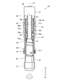
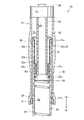
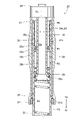
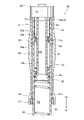
- FIG. It is sectional drawing of the main part of the front fork shown in FIG. It is a figure explaining the front fork in the state where the spring shown in FIG. 2 is the most extended. It is a figure explaining the action when a predetermined predetermined load is applied to the front fork shown in FIG. 2. It is a figure explaining the front fork in the state where the spring shown in FIG. 2 is the most compressed.
- FIG. It is sectional drawing of the main part of the front fork according to Example 3.
- left and right refer to left and right based on the occupants of the two-wheeled vehicle
- front and rear refer to front and rear based on the traveling direction of the two-wheeled vehicle.
- Fr indicates the front
- Rr indicates the rear
- Up indicates the top
- Dn indicates the bottom.
- the form shown in the attached figure is an example of the present invention, and the present invention is not limited to this form.
- the front fork 20 will be described with reference to an example mounted on a two-wheeled vehicle 10 (saddle-riding vehicle 10).
- the front fork 20 is not limited to the two-wheeled vehicle 10, but can be mounted on a tricycle, a four-wheeled vehicle, or the like as long as it is a saddle-riding vehicle in which an occupant straddles the vehicle body 11.
- the two-wheeled vehicle 10 includes a vehicle body 11, an engine 12 as a power source supported in the lower center of the vehicle body 11, and a front fork 20 provided at the front of the vehicle body 11 to absorb an impact received from unevenness of the road surface. It has a front wheel 14 that is sandwiched between these front forks 20 and rotatably supported.
- the two-wheeled vehicle 10 further has a handle pipe 15 arranged above the front fork 20 to steer the front wheels 14, and a seat 16 provided above the engine 12 on which the occupant Mn sits.
- the two-wheeled vehicle 10 includes a swing arm 17 extending rearward from the rear portion of the vehicle body 11 so as to be swingable in the vertical direction, a rear wheel 18 rotatably supported by the swing arm 17, and a rear portion of the vehicle body 11. It has left and right rear suspensions 19 that are hung from the swing arm 17 to the swing arm 17.
- the front fork 20 is an inverted front fork and is bridged between the vehicle body 11 and the front wheels 14.
- the front fork 20 will be described in detail in the following figures.
- the structure of the front fork 20 is the same on the left side and the right side of the front wheel 14, and the explanation will be given using the front fork 20 on the right side as an example.
- the description of the front fork on the left side will be omitted.
- the left and right configurations of the front fork 20 can be changed according to the purpose. At this time, either the left or right front fork may be the front fork 20 described below.
- a predetermined load more specifically, a load in a state where one occupant Mn (see FIG. 1) is on the front fork 20 is applied to the front fork 20. That is, the front fork 20 is compressed by a predetermined amount as compared with the state where the predetermined load is not applied.
- a predetermined load is applied to the front fork 20 when the occupant Mn, which is a weight selected from the range of 60 kg or more and 80 kg or less including the equipment, gets on the motorcycle 10. It can be a load.
- the front fork 20 further rotates the front wheel 14 provided on the side portion of the front wheel 14 (see FIG. 1) and the lid 26 which is screwed onto the inner peripheral surface of the upper end of the outer tube 21 to close the upper end of the outer tube 21. It has an axle holder 27 that is capable of supporting and closing the lower end of the inner tube 22.
- the front fork 20 has a hollow tube body 28 whose upper end is supported by the outer tube 21 via a lid 26 and whose lower end faces the inside of the inner tube 22, and a tube body 28 whose diameter is expanded. It is a lower end portion and has a piston 29 that generates a damping force when the oil 24 flows along the outer peripheral surface.
- the front fork 20 is further supported by a guide member 32 supported by the inner peripheral surface of the inner tube 22 and guides the axial movement of the tubular body 28, and a spring arranged between the guide member 32 and the piston 29. It has a second spring 33, which is.
- annular fixing bushes 35 and 36 fixed at two upper and lower positions so as to abut on the outer peripheral surface of the inner tube 22 are provided on the inner peripheral surface of the outer tube 21, and further suppress the leakage of the oil 24.
- the sealing member 37 is fixed to the lower end of the outer tube 21.
- the fixed bush 35 located relatively above may be appropriately referred to as "upper fixed bush 35”
- the fixed bush 36 located relatively lower may be appropriately “fixed to the lower part”.
- Bush 36 ".
- the portion inside the inner tube 22 and below the piston 29 is referred to as the compression side oil chamber R2.
- the portion sandwiched between the outer peripheral surface of the tubular body 28 and the inner peripheral surface of the inner tube 22 is referred to as an extension side oil chamber R3.
- the portion inside the tubular body 28 is referred to as a tubular body chamber R4.
- the portion above the lower end of the guide member 32 and excluding the annular oil chamber R1 is oiled. It is called a reservoir R5.
- the inner peripheral surface of the outer tube 21 has a groove portion 21a, which is a groove into which the upper fixing bush 35 is fitted.
- the lower end of the outer tube 21 is a diameter-expanded portion 21b.
- the enlarged diameter portion 21b is provided with a lower fixing bush 36 and a sealing member 37.
- the inner tube 22 is supported by the axle holder 27.
- the lower end of the inner tube 22 is arranged below the lower end of the outer tube 21, and is provided so as to be able to move forward and backward relative to the outer tube 21.
- the upper end of the inner tube 22 is formed to be thinner than other parts.
- the guide member 32 is fitted along the inner peripheral surface of the thin-walled portion.
- the lower end of the thin-walled portion is formed in a stepped shape in the radial direction. This restricts the downward movement of the guide member 32.
- the inner tube 22 has four communication holes 22a that communicate the inside and the outside of the inner tube 22 and penetrate the inner tube 22 in the radial direction, for example, at equal intervals in the circumferential direction.
- the spring 23 is, for example, a compression coil spring in which the lower end is in contact with the axle holder 27 and the upper end is in contact with the lower end surface of the tubular body 28.
- the tube body 28 extends along the axis CL of the outer tube 21. Further, the tubular body 28 has a first through hole 28a penetrating the tubular body 28 in a direction intersecting the axial direction at the central portion in the axial direction, and an axial direction below the first through hole 28a. It has a second through hole 28b that penetrates the pipe body 28 in the intersecting direction.
- the axial length of the front fork 20 when the front fork 20 is in the most extended state is L1 (cm), and the front fork 20 is most contracted by applying a force in the direction of contracting the front fork 20.
- the axial length of the front fork 20 in the state is L2 (cm).
- the "center portion in the axial direction" provided with the first through hole 28a is a portion corresponding to the height of the oil level 24a when the front fork 20 is contracted by 30% or more and 50% or less of the total stroke L. Is.
- the air in the tubular chamber R4 is compressed more than the air in the oil reservoir R5, and a difference occurs between the air pressure in the tubular chamber R4 and the air pressure in the oil reservoir R5. Since this appears as a damping force resistance, a damping force corresponding to the stroke amount can be obtained. Therefore, when the first through hole 28a is immersed in the oil 24, a large damping force is obtained during braking or the like in which the stroke amount is large, and the damping force is small during normal running where the stroke amount is small. , The ride quality can be improved.
- the first through hole 28a is located at the same height as the oil level 24a of the oil 24. ing. In the basic state, the first through hole 28a may be located below the oil level 24a of the oil 24. In the present invention, the first through hole 28a provided in the central portion in the axial direction of the pipe body 28 is located near the oil level 24a of the oil 24 in the basic state, preferably with the oil level 24a of the oil 24 in the basic state. It is provided at the same position.
- the number of first through holes 28a is not particularly limited.
- the number of the first through holes 28a can be any number of 1 or more.
- the axial direction of the front fork 20 is deviated from the vertical direction, and the front fork 20 is tilted. Even in this state, a large damping force can be obtained during braking, etc., where the stroke amount is large, and the damping force becomes small during normal driving, where the stroke amount is small, making it possible to improve the riding comfort.
- the number of the first through holes 28a is a plurality (2 or more).
- the second through hole 28b is located below the lower end of the guide member 32 in the basic state shown in FIG.
- the number of the second through holes 28b is not particularly limited.
- the piston 29 is integrally formed with the pipe body 28 by expanding the diameter of the lower end of the pipe body 28.
- the outer peripheral surface of the piston 29 has a groove-shaped portion provided with an annular member 29a formed of a piston ring.
- the oil 24 can pass between the outer peripheral surface of the annular member 29a and the inner peripheral surface of the inner tube 22. Damping occurs as the oil 24 passes.
- the guide member 32 is a cylindrical member, the upper end of which protrudes outward in diameter, and the lower end of which protrudes inward of the diameter.
- the guide member 32 is fixed by fitting the protruding portion of the upper end into the upper end of the inner tube 22.
- the protruding portion at the upper end of the guide member 32 is in contact with the stepped portion provided at the upper end of the inner tube 22.
- the guide member 32 has a through hole 32a having substantially the same diameter as the communication hole 22a at a portion on the inner peripheral side having the same height as the communication hole 22a. That is, the communication hole 22a and the through hole 32a are continuous in the radial direction orthogonal to the axis CL. By having the communication hole 22a and the through hole 32a, a part of the oil in the oil reservoir R5 flows into the annular oil chamber R1.
- the inner peripheral surface of the lower end of the guide member 32 has a groove-shaped storage portion continuous in the circumferential direction.
- a check valve 32b that allows the passage of the oil 24 in only one direction is fitted in the groove-shaped storage portion.
- the check valve 32b is in contact with the outer peripheral surface of the pipe body 28 and constitutes a part of the guide member 32.
- the lower end of the guide member 32 is always located above the upper end of the piston 29. That is, the guide member 32 is located above the piston 29.
- the second spring 33 is a compression coil spring.
- the second spring 33 acts in a direction of restricting the extension when the outer tube 21 and the inner tube 22 extend beyond a predetermined amount.
- Both the fixing bushes 35 and 36 can be composed of resin parts formed in a ring shape.
- the fixing bushes 35 and 36 hold the inner tube 22 so as to be movable in the axial direction.
- the upper fixed bush 35 can be said to be a fixed bush arranged at the uppermost position.
- seal member 37 for example, a rubber O-ring provided along the inner peripheral surface of the lower end of the outer tube 21 is used.
- the outer tube 21, the tube body 28, the piston 29, the fixed bushes 35 and 36, and the seal member 37 can be integrally displaced with respect to the inner tube 22.
- the inner tube 22 and the guide member 32 can be integrally displaced with respect to the outer tube 21.
- the spring 23 is in the most extended state. That is, the spring 23 shown in FIG. 3 is in a more extended state than the spring 23 shown in FIG.
- the second through hole 28b is located above the check valve 32b. In other words, the second through hole 28b is located above the portion where the guide member 32 and the pipe body 28 come into contact with each other. In other words, in the state where the spring 23 is most extended, the second through hole 28b is located above the portion where the guide member 32 and the cylinder 28 come into contact with each other.
- the first through hole 28a When the first through hole 28a is above the oil level 24a, the first through hole 28a does not directly contribute to the generation of damping force.
- the second through hole 28b When the second through hole 28b is located above the check valve 32b, the pipe chamber R4 and the oil reservoir chamber R5 are connected to each other via the second through hole 28b.
- FIG. 4 shows a front fork 20 to which a load in the compression direction is applied rather than the basic state shown in FIG. FIG. 4 corresponds to, for example, a state in which the brake is applied during traveling.
- the outer tube 21, the tube body 28, the piston 29, the fixed bushes 35 and 36, and the seal member 37 are displaced downward with respect to the inner tube 22.
- FIG. 5 shows the front fork 20 in which the spring 23 is most compressed.
- the spring 23 may be compressed to a position where the upper end of the inner tube 22 approaches the lid body 26.
- the lower end of the first through hole 28a is located below the guide member 32.
- the first through hole 28a is provided at a portion located below the check valve 32b.
- the first through hole 28a and the second through hole 28b face the extension side oil chamber R3.
- the tube chamber R4 and the oil reservoir R5 are not connected to each other.
- the communication hole 22a and the through hole 32a are located above the upper fixing bush 35.
- the communication hole 22a and the through hole 32a are provided at a portion above the upper fixing bush 35 when the spring 23 is most compressed.
- the oil reservoir R5 and the annular oil chamber R1 are connected to each other via a communication hole 22a and a through hole 32a.
- the front fork 20 is a tubular outer tube 21 and a tubular member having an upper end inserted into the outer tube 21, and the lower end is arranged below the lower end of the outer tube 21 to form an outer. It includes an inner tube 22 that is provided so as to be relatively movable (advance and retreat) with respect to the tube 21.
- the outer tube 21 and the inner tube 22 are subjected to a force in a direction to separate them from each other by the spring 23.
- the inside of the inner tube 22 is filled with oil 24.
- a hollow tube body 28 having an upper end supported by the outer tube 21 and extending along the axis CL of the outer tube 21 is provided.
- the expanded lower end portion of the tubular body 28 is the piston 29, and a damping force is generated when the oil 24 passes along the outer peripheral surface of the piston 29.
- the pipe body 28 has a first through hole 28a penetrating the pipe body 28 in a direction intersecting the axial direction at the central portion in the axial direction of the pipe body 28, and a pipe below the first through hole 28a. It has a second through hole 28b that penetrates the pipe body 28 in a direction intersecting the axial direction of the body 28.
- the first through hole 28a is at the same height as the oil level 24a of the oil 24 or below the oil level 24a when the spring 23 is compressed by applying a predetermined predetermined load. It can also be said that it is located.
- the central portion in the axial direction of the tubular body 28 becomes the oil level 24a. It is set to be the same height.
- the first through hole 28a can be arranged in the vicinity of the oil surface 24a when the occupant Mn is seated on the seat 16. Until the first through hole 28a is immersed in the oil surface 24a, air passes through the first through hole 28a and no damping force resistance is generated, so that the riding comfort can be improved.
- the first through hole 28a is immersed in the oil 24, a large damping force is obtained during braking or the like in which the stroke amount is large, and the damping force is small during normal running where the stroke amount is small. , The ride quality can be improved. Further, since the first through hole 28a is in the oil, air is not supplied to the compression side oil chamber R2 until the first through hole 28a reaches the oil surface 24a in the extension stroke, so that the oil level 24a in the pipe body 28 It becomes possible to suppress the decrease.
- the tubular body 28 has a plurality of first through holes 28a at different positions in the circumferential direction thereof. Thereby, the variation in the distance between the oil level 24a and the first through hole 28a due to the caster angle can be minimized. As a result, the above effect of the front fork 20 can be easily obtained.
- the front fork 20 has a guide member 32 that is supported on the inner peripheral surface of the inner tube 22 above the piston 29 and guides the axial movement of the tube body 28. Further, in the state where the spring 23 is most compressed, the first through hole 28a is located below the guide member 32. As a result, the first through hole 28a is switched so as to communicate with the extension side oil chamber R3 before the spring 23 is in the most compressed state. As a result, since the oil lock effect is obtained, it becomes easy to avoid the situation where the upper end of the inner tube 22 comes into contact with the lid body 26.
- the second through hole 28b is located above the lower end of the guide member 32.
- the pipe chamber R4 and the oil reservoir chamber R5 are secondly penetrated. It can communicate through the hole 28b.
- the height of the oil surface 24a can be made uniform, and air can be prevented from flowing into the compression side oil chamber R2.
- the oil lock effect can be obtained in the extension stroke.
- the outer peripheral surface of the inner tube 22 abuts on two (plural) annular fixing bushes 35, 36 fixed to the inner peripheral surface of the outer tube 21, and the inner tube 22 is inside and outside the inner tube 22. It has a communication hole 22a that communicates with the above. In the most compressed state of the spring 23, the communication hole 22a is located above the upper fixed bush 35 (the uppermost fixed bush 35).
- the oil level height of the annular oil chamber R1 and the oil level height of the oil reservoir R5 can be made uniform, so that the oil level variation can be suppressed. As a result, it becomes easy to manage the oil level during maintenance of the front fork 20.
- the front fork 20 is provided on the guide member 32 (provided on the outer peripheral surface of the pipe body 28), allows an axial flow of oil from top to bottom, and allows the oil to flow from bottom to top in the axial direction. It further has a check valve 32b that regulates the flow, and the check valve 32b is located below the communication hole 22a.
- Example 2 Next, Example 2 will be described with reference to the drawings.
- the front fork 20A according to the second embodiment slides the inner tube 22X by the lower fixing bush 36 fixed to the inner peripheral surface of the outer tube 21 and the sliding bush 45 fixed to the outer peripheral surface of the inner tube 22X. Holds possible.
- Other basic configurations are the same as those of the front fork 20. Regarding the configuration common to the front fork 20, the reference numerals are used and detailed description thereof will be omitted as appropriate.
- the sliding bush 45 is fitted into a groove continuously formed in the circumferential direction on the outer peripheral surface of the inner tube 22X.
- the outer peripheral surface of the sliding bush 45 is in contact with the inner peripheral surface of the outer tube 21.
- the sliding bush 45 can move with respect to the outer tube 21 together with the inner tube 22X.
- the communication hole 22a is formed below the sliding bush 45.
- the outer tube 21, the tube body 28, the piston 29, the lower fixing bush 36, and the seal member 37 can be integrally displaced with respect to the inner tube 22X.
- the inner tube 22X, the guide member 32, and the sliding bush 45 can be integrally displaced with respect to the outer tube 21.
- the front fork 20A described above can also have the same effect as the front fork 20, and the two-wheeled vehicle equipped with the front fork 20A can also have the same effect as the two-wheeled vehicle equipped with the front fork 20.
- the front fork 20A has an annular sliding bush 45 fixed to the outer peripheral surface of the inner tube 22X and sliding on the inner peripheral surface of the outer tube 21. Since it is easier to form a groove for fitting the bush on the outer peripheral surface of the inner tube 22X than to form a groove for fitting the bush on the inner peripheral surface of the outer tube 21, the sliding bush 45 is provided. , The processing cost can be reduced. This makes it possible to reduce the cost of the front fork 20A.
- the inner tube 22X has a communication hole 22a that communicates the inside and the outside of the inner tube 22X below the sliding bush 45. This makes it possible to suck and discharge oil between the annular oil chamber R1 and the oil reservoir R5 through the communication hole 22a.
- Example 3 Next, Example 3 will be described with reference to the drawings.
- the front fork 20B has a throttle portion 53 inside the tubular body 28 to reduce the flow path area.
- Other basic configurations are the same as those of the front fork 20.
- the reference numerals are used and detailed description thereof will be omitted as appropriate.
- the throttle portion 53 is composed of a tubular member fixed to the inner peripheral surface of the tubular body 28. At the center of the diaphragm portion 53, there is a diaphragm hole 53a penetrating in the vertical direction along the axis CL. The area of the flow path through which the oil 24 flows is reduced from the cross-sectional area inside the tubular body 28 to the cross-sectional area inside the throttle hole 53a at the portion where the throttle portion 53 is formed.
- the front fork 20B described above can also have the same effect as the front fork 20, and the two-wheeled vehicle equipped with the front fork 20B can also have the same effect as the two-wheeled vehicle equipped with the front fork 20.
- the throttle portion 53 inside the tubular body 28 to reduce the flow path area of the oil, the air accumulated above the tubular body chamber R4 is pressurized, and the pressure of the air rises in the tubular body 28. Even if the oil level 24a is difficult to rise and it is difficult to generate a damping force, the throttle portion 53 can generate the damping force, so that the damping force can be stably generated.
- the present invention can also be applied to a front fork in which the outer peripheral surface of the inner tube can be directly contacted with the outer peripheral surface of the outer tube. Further, when the bushes are fixed to the inner peripheral surface of the outer tube or the outer peripheral surface of the inner tube, the number thereof is not particularly limited, and it is possible to provide three or more bushes.
- the present invention is not limited to the examples as long as the actions and effects of the present invention are exhibited.
- the front fork of the present invention is suitable for a saddle-riding vehicle.
Landscapes
- Engineering & Computer Science (AREA)
- General Engineering & Computer Science (AREA)
- Mechanical Engineering (AREA)
- Fluid-Damping Devices (AREA)
- Axle Suspensions And Sidecars For Cycles (AREA)
Abstract
Description
図1を参照する。フロントフォーク20について、二輪車10(鞍乗り型車両10)に搭載された例を用いて説明する。なお、フロントフォーク20は、二輪車10に限らず、三輪車や四輪車等であっても乗員が車体11に跨って乗車する鞍乗り型車両であれば、搭載することができる。
次に、実施例2を図面に基づいて説明する。
次に、実施例3を図面に基づいて説明する。
11…車体
14…前輪
20、20A、20B…フロントフォーク
21…アウターチューブ
22…インナーチューブ、22a…連通孔
23…ばね
24…オイル、24a…油面
28…管体、28a…第1貫通孔、28b…第2貫通孔
29…ピストン
32…ガイド部材、32b…チェック弁
35…上部固定ブッシュ(固定ブッシュ)
36…下部固定ブッシュ(固定ブッシュ)
45…摺動ブッシュ
53…絞り部
CL…軸線
Mn…乗員
Claims (12)
- 筒状を呈するアウターチューブと、
このアウターチューブ内に上端が挿入されている筒状の部材であって、下端が前記アウターチューブの下端よりも下側に配置され、前記アウターチューブに対して相対的に移動可能に設けられているインナーチューブと、
前記アウターチューブ及び前記インナーチューブに対し、これらを互いに離間させる向きの力を付与するばねと、
前記インナーチューブの内部に充填されているオイルと、
上端が前記アウターチューブに支持されていると共に前記アウターチューブの軸線に沿って延びている中空状の管体と、
拡径されている前記管体の下端部位であり、外周面に沿って前記オイルが通過する際に減衰力を発生させるピストンと、を備え、
前記管体は、前記管体の軸方向の中央部で、前記軸方向と交差する方向に前記管体を貫通している第1貫通孔と、この第1貫通孔よりも下方で前記軸方向と交差する方向に前記管体を貫通している第2貫通孔と、を有する、フロントフォーク。 - 筒状を呈するアウターチューブと、
このアウターチューブ内に上端が挿入されている筒状の部材であって、下端が前記アウターチューブの下端よりも下側に配置され、前記アウターチューブに対して相対的に移動可能に設けられているインナーチューブと、
前記アウターチューブ及び前記インナーチューブに対し、これらを互いに離間させる向きの力を付与するばねと、
前記インナーチューブの内部に充填されているオイルと、
上端が前記アウターチューブに支持されていると共に前記アウターチューブの軸線に沿って延びている中空状の管体と、
この管体の下端が拡径されることにより前記管体に一体的に備えられ、外周面に沿って前記オイルが通過する際に減衰力を発生させるピストンと、を備え、
前記管体は、
予め定められた所定の荷重が加わることにより前記ばねが圧縮されている基本状態のときに、前記オイルの油面と同じ高さ、又は前記オイルの油面よりも下方で前記管体の軸方向と交差する方向に前記管体を貫通している第1貫通孔と、
この第1貫通孔よりも下方で前記軸方向と交差する方向に前記管体を貫通する第2貫通孔と、を有する、フロントフォーク。 - 前記管体は、前記管体の周方向の異なる位置に、前記第1貫通孔を複数有する、請求項1又は請求項2に記載のフロントフォーク。
- 前記ピストンよりも上方で前記インナーチューブの内周面に支持され、前記管体の前記軸方向への移動を案内するガイド部材を有し、
前記ばねが最も圧縮されている状態において、前記第1貫通孔は、前記ガイド部材よりも下方に位置している請求項1~請求項3のいずれか1項に記載のフロントフォーク。 - 前記ピストンよりも上方で前記インナーチューブの内周面に支持され、前記管体の前記軸方向への移動を案内するガイド部材を有し、
前記ばねが最も伸びている状態で、前記第2貫通孔は、前記ガイド部材の下端よりも上方に位置している請求項1~請求項4のいずれか1項に記載のフロントフォーク。 - 前記インナーチューブの外周面は、前記アウターチューブの内周面に固定された円環状の複数の固定ブッシュに当接し、
前記インナーチューブは、前記インナーチューブの内側と外側とを連通する連通孔を有し、
前記ばねが最も圧縮されている状態で、前記連通孔は、最も上方に配置されている前記固定ブッシュよりも上方に位置している請求項1~請求項5のいずれか1項に記載のフロントフォーク。 - 前記ガイド部材に設けられ、前記軸方向の上から下へと向かう前記オイルの流れを許容し、前記軸方向の下から上へと向かう前記オイルの流れを規制するチェック弁をさらに有し、
前記チェック弁は、前記連通孔よりも下方に位置している請求項5に記載のフロントフォーク。 - 前記インナーチューブの外周面に固定され、前記アウターチューブの内周面を摺動する円環状の摺動ブッシュを有する請求項1~請求項5のいずれか1項に記載のフロントフォーク。
- 前記インナーチューブは、前記摺動ブッシュよりも下方に、前記インナーチューブの内側と外側とを連通する連通孔を有する請求項8に記載のフロントフォーク。
- 前記管体の内部に、前記オイルの流路面積を低減する絞り部を有する請求項1~請求項9のいずれか1項に記載のフロントフォーク。
- 筒状を呈するアウターチューブと、
このアウターチューブ内に上端が挿入されている筒状の部材であって、下端が前記アウターチューブの下端よりも下側に配置され、前記アウターチューブに対して相対的に移動可能に設けられているインナーチューブと、
前記アウターチューブ及び前記インナーチューブに対し、これらを互いに離間させる向きの力を付与するばねと、
前記インナーチューブの内部に充填されているオイルと、
上端が前記アウターチューブに支持されていると共に前記アウターチューブの軸線に沿って延びている中空状の管体と、
拡径されている前記管体の下端部位であり、外周面に沿って前記オイルが通過する際に減衰力を発生させるピストンと、
前記アウターチューブの内周面に固定された複数の円環状の固定ブッシュと、
前記ピストンよりも上方で前記インナーチューブの内周面に支持され、前記管体の前記軸方向への移動を案内するガイド部材と、
このガイド部材に支持され、前記管体の外周面に当接し、前記軸方向の上から下へと向かう前記オイルの流れを許容し、前記軸方向の下から上へと向かう前記オイルの流れを規制するチェック弁と、を備え、
前記管体は、
予め定められた所定の荷重が加わることにより前記ばねが圧縮されている基本状態のときに、前記オイルの油面と同じ高さ、又は前記オイルの油面よりも下方で前記管体の軸方向と交差する方向に前記管体を貫通している第1貫通孔と、
この第1貫通孔よりも下方で前記軸方向と交差する方向に前記管体を貫通する第2貫通孔と、を有し、
前記第1貫通孔は、前記管体の周方向の異なる位置に複数備えられ、前記ばねが最も圧縮されている状態において、前記ガイド部材よりも下方に位置し、
前記第2貫通孔は、前記ばねが最も伸びている状態で、前記ガイド部材の下端よりも上方に位置し、
前記インナーチューブは、前記インナーチューブの内側と外側とを連通する連通孔を有し、
前記連通孔は、前記ばねが最も圧縮されている状態で、最も上方に配置されている前記固定ブッシュよりも上方に位置し、
前記チェック弁は、前記ばねが最も圧縮されている状態で、前記連通孔よりも下方に位置する、フロントフォーク。 - 車体及び前輪、並びに、前記車体と前記前輪とに架け渡された請求項1~請求項11のいずれか1項に記載のフロントフォークを備える、鞍乗り型車両。
Priority Applications (2)
| Application Number | Priority Date | Filing Date | Title |
|---|---|---|---|
| PCT/JP2020/043944 WO2022113226A1 (ja) | 2020-11-26 | 2020-11-26 | フロントフォーク、及び、鞍乗り型車両 |
| JP2020566310A JP6895026B1 (ja) | 2020-11-26 | 2020-11-26 | フロントフォーク、及び、鞍乗り型車両 |
Applications Claiming Priority (1)
| Application Number | Priority Date | Filing Date | Title |
|---|---|---|---|
| PCT/JP2020/043944 WO2022113226A1 (ja) | 2020-11-26 | 2020-11-26 | フロントフォーク、及び、鞍乗り型車両 |
Publications (1)
| Publication Number | Publication Date |
|---|---|
| WO2022113226A1 true WO2022113226A1 (ja) | 2022-06-02 |
Family
ID=76540467
Family Applications (1)
| Application Number | Title | Priority Date | Filing Date |
|---|---|---|---|
| PCT/JP2020/043944 Ceased WO2022113226A1 (ja) | 2020-11-26 | 2020-11-26 | フロントフォーク、及び、鞍乗り型車両 |
Country Status (2)
| Country | Link |
|---|---|
| JP (1) | JP6895026B1 (ja) |
| WO (1) | WO2022113226A1 (ja) |
Cited By (1)
| Publication number | Priority date | Publication date | Assignee | Title |
|---|---|---|---|---|
| WO2026074665A1 (ja) * | 2024-10-03 | 2026-04-09 | Astemo株式会社 | 緩衝器及び緩衝器の製造方法 |
Families Citing this family (1)
| Publication number | Priority date | Publication date | Assignee | Title |
|---|---|---|---|---|
| WO2025186885A1 (ja) * | 2024-03-05 | 2025-09-12 | Astemo株式会社 | 緩衝器 |
Citations (8)
| Publication number | Priority date | Publication date | Assignee | Title |
|---|---|---|---|---|
| JPH02128691U (ja) * | 1989-03-31 | 1990-10-23 | ||
| JP2005054906A (ja) * | 2003-08-05 | 2005-03-03 | Kayaba Ind Co Ltd | フロントフォーク |
| JP2006307906A (ja) * | 2005-04-26 | 2006-11-09 | Showa Corp | フロントフォーク |
| JP2007146948A (ja) * | 2005-11-25 | 2007-06-14 | Showa Corp | フロントフォーク |
| JP2010038172A (ja) * | 2008-07-31 | 2010-02-18 | Showa Corp | 油圧緩衝器 |
| JP2010151310A (ja) * | 2008-11-27 | 2010-07-08 | Showa Corp | フロントフォークのオイルロック装置 |
| JP2011231796A (ja) * | 2010-04-23 | 2011-11-17 | Showa Corp | 油圧緩衝器 |
| JP2015197104A (ja) * | 2014-03-31 | 2015-11-09 | 株式会社ショーワ | 懸架装置 |
-
2020
- 2020-11-26 WO PCT/JP2020/043944 patent/WO2022113226A1/ja not_active Ceased
- 2020-11-26 JP JP2020566310A patent/JP6895026B1/ja active Active
Patent Citations (8)
| Publication number | Priority date | Publication date | Assignee | Title |
|---|---|---|---|---|
| JPH02128691U (ja) * | 1989-03-31 | 1990-10-23 | ||
| JP2005054906A (ja) * | 2003-08-05 | 2005-03-03 | Kayaba Ind Co Ltd | フロントフォーク |
| JP2006307906A (ja) * | 2005-04-26 | 2006-11-09 | Showa Corp | フロントフォーク |
| JP2007146948A (ja) * | 2005-11-25 | 2007-06-14 | Showa Corp | フロントフォーク |
| JP2010038172A (ja) * | 2008-07-31 | 2010-02-18 | Showa Corp | 油圧緩衝器 |
| JP2010151310A (ja) * | 2008-11-27 | 2010-07-08 | Showa Corp | フロントフォークのオイルロック装置 |
| JP2011231796A (ja) * | 2010-04-23 | 2011-11-17 | Showa Corp | 油圧緩衝器 |
| JP2015197104A (ja) * | 2014-03-31 | 2015-11-09 | 株式会社ショーワ | 懸架装置 |
Cited By (1)
| Publication number | Priority date | Publication date | Assignee | Title |
|---|---|---|---|---|
| WO2026074665A1 (ja) * | 2024-10-03 | 2026-04-09 | Astemo株式会社 | 緩衝器及び緩衝器の製造方法 |
Also Published As
| Publication number | Publication date |
|---|---|
| JPWO2022113226A1 (ja) | 2022-06-02 |
| JP6895026B1 (ja) | 2021-06-30 |
Similar Documents
| Publication | Publication Date | Title |
|---|---|---|
| CN113498396B (zh) | 缓冲器 | |
| US8499905B2 (en) | Front fork | |
| JP6368423B2 (ja) | 乗り物用油圧式緩衝装置 | |
| JP2017008970A (ja) | 減衰力可変式緩衝器 | |
| JP6895026B1 (ja) | フロントフォーク、及び、鞍乗り型車両 | |
| JP7002266B2 (ja) | 懸架装置 | |
| US9488243B2 (en) | Damper with a vehicle height adjusting function | |
| US12071195B2 (en) | Damper apparatus | |
| JP5383451B2 (ja) | 油圧緩衝器 | |
| US12139231B2 (en) | Hydraulic shock absorber | |
| JP6966665B1 (ja) | フロントフォーク、及び、鞍乗り型車両 | |
| JP4056268B2 (ja) | 油圧緩衝器の作動油の給排装置 | |
| JP2529993Y2 (ja) | 倒立型フロントフォーク | |
| JP4050076B2 (ja) | 自動二輪車のフロントフォーク | |
| JP7419153B2 (ja) | エアサスペンション装置、及び、鞍乗り型車両 | |
| JP2529994Y2 (ja) | 倒立型フロントフォーク | |
| JP7051614B2 (ja) | フロントフォーク | |
| WO2019082610A1 (ja) | フロントフォーク | |
| JP2001349367A (ja) | フロントフォーク | |
| WO2020202500A1 (ja) | 緩衝器 | |
| JP2011214585A (ja) | フロントフォーク | |
| JP2010261516A (ja) | 減衰部構造 | |
| WO2018163523A1 (ja) | 車両用緩衝器 | |
| JP2023016088A (ja) | 油圧緩衝器 | |
| JPH0450018A (ja) | 車両用油圧緩衝器の車高調整装置 |
Legal Events
| Date | Code | Title | Description |
|---|---|---|---|
| ENP | Entry into the national phase |
Ref document number: 2020566310 Country of ref document: JP Kind code of ref document: A |
|
| 121 | Ep: the epo has been informed by wipo that ep was designated in this application |
Ref document number: 20963491 Country of ref document: EP Kind code of ref document: A1 |
|
| WWE | Wipo information: entry into national phase |
Ref document number: 202347027067 Country of ref document: IN |
|
| NENP | Non-entry into the national phase |
Ref country code: DE |
|
| 122 | Ep: pct application non-entry in european phase |
Ref document number: 20963491 Country of ref document: EP Kind code of ref document: A1 |