WO2022113172A1 - 位置推定装置、設備機器システム、位置推定方法、および、プログラム - Google Patents
位置推定装置、設備機器システム、位置推定方法、および、プログラム Download PDFInfo
- Publication number
- WO2022113172A1 WO2022113172A1 PCT/JP2020/043682 JP2020043682W WO2022113172A1 WO 2022113172 A1 WO2022113172 A1 WO 2022113172A1 JP 2020043682 W JP2020043682 W JP 2020043682W WO 2022113172 A1 WO2022113172 A1 WO 2022113172A1
- Authority
- WO
- WIPO (PCT)
- Prior art keywords
- equipment
- relative position
- installation
- absolute
- absolute position
- Prior art date
- Legal status (The legal status is an assumption and is not a legal conclusion. Google has not performed a legal analysis and makes no representation as to the accuracy of the status listed.)
- Ceased
Links
Images


Classifications
-
- G—PHYSICS
- G01—MEASURING; TESTING
- G01S—RADIO DIRECTION-FINDING; RADIO NAVIGATION; DETERMINING DISTANCE OR VELOCITY BY USE OF RADIO WAVES; LOCATING OR PRESENCE-DETECTING BY USE OF THE REFLECTION OR RERADIATION OF RADIO WAVES; ANALOGOUS ARRANGEMENTS USING OTHER WAVES
- G01S5/00—Position-fixing by co-ordinating two or more direction or position line determinations; Position-fixing by co-ordinating two or more distance determinations
- G01S5/02—Position-fixing by co-ordinating two or more direction or position line determinations; Position-fixing by co-ordinating two or more distance determinations using radio waves
- G01S5/0284—Relative positioning
-
- G—PHYSICS
- G01—MEASURING; TESTING
- G01S—RADIO DIRECTION-FINDING; RADIO NAVIGATION; DETERMINING DISTANCE OR VELOCITY BY USE OF RADIO WAVES; LOCATING OR PRESENCE-DETECTING BY USE OF THE REFLECTION OR RERADIATION OF RADIO WAVES; ANALOGOUS ARRANGEMENTS USING OTHER WAVES
- G01S5/00—Position-fixing by co-ordinating two or more direction or position line determinations; Position-fixing by co-ordinating two or more distance determinations
- G01S5/02—Position-fixing by co-ordinating two or more direction or position line determinations; Position-fixing by co-ordinating two or more distance determinations using radio waves
- G01S5/0269—Inferred or constrained positioning, e.g. employing knowledge of the physical or electromagnetic environment, state of motion or other contextual information to infer or constrain a position
-
- G—PHYSICS
- G01—MEASURING; TESTING
- G01S—RADIO DIRECTION-FINDING; RADIO NAVIGATION; DETERMINING DISTANCE OR VELOCITY BY USE OF RADIO WAVES; LOCATING OR PRESENCE-DETECTING BY USE OF THE REFLECTION OR RERADIATION OF RADIO WAVES; ANALOGOUS ARRANGEMENTS USING OTHER WAVES
- G01S5/00—Position-fixing by co-ordinating two or more direction or position line determinations; Position-fixing by co-ordinating two or more distance determinations
- G01S5/02—Position-fixing by co-ordinating two or more direction or position line determinations; Position-fixing by co-ordinating two or more distance determinations using radio waves
- G01S5/12—Position-fixing by co-ordinating two or more direction or position line determinations; Position-fixing by co-ordinating two or more distance determinations using radio waves by co-ordinating position lines of different shape, e.g. hyperbolic, circular, elliptical or radial
Definitions
- This disclosure relates to a position estimation device, an equipment system, a position estimation method, and a program.
- equipment such as air conditioners and lighting equipment have been installed on the floors of buildings such as office buildings and commercial buildings.
- Such equipment is controlled by a controller connected by wire or wirelessly so that the user on the floor can spend comfortably.
- the controller enhances the comfort of the user by appropriately controlling the equipment in the vicinity according to the position of the user existing on the floor. Therefore, the controller stores information about the position where the equipment is installed, that is, the installation position.
- the installation position was generally set manually by a worker who measured the equipment, but recently, the controller automatically sets the equipment.
- a mechanism for estimating the installation position has also been developed.
- Patent Document 1 discloses a technique of a position estimation device that estimates the position of a wireless device through transmission / reception of a wireless signal between wireless devices.
- This position estimator uses the distance between devices measured by one radio device to the other radio device, the measurement data regarding the certainty of the distance between the devices, and the distance between devices and the measurement data collected in the past. Based on this, the position of the wireless device is estimated.
- the position estimation device disclosed in Patent Document 1 utilizes the inter-device distance and measurement data collected in the past, and it is stated that the accuracy will be gradually improved in the process of repeatedly estimating the position of the wireless device. Intended. Therefore, when estimating the position of the wireless device for the first time, there is a concern that sufficient accuracy cannot be obtained. That is, in the position estimation device disclosed in Patent Document 1, it is necessary to repeat the position estimation a plurality of times in order to obtain sufficient accuracy, and it takes a long time to complete the position estimation. There was a problem.
- the present disclosure has been made to solve the above-mentioned problems, and is a position estimation device, an equipment system, a position estimation method, and a program capable of estimating the installation position of equipment with higher accuracy.
- the purpose is to provide.
- the position estimation device is A position estimation device that is communicably connected to two or more equipment including a first equipment whose installation position is known and a second equipment whose installation position is unknown.
- a relative position receiving means for receiving information indicating a relative position between the first equipment and the second equipment, which is sent from any of the equipment.
- Absolute position of the second equipment based on the relative position indicated by the information received by the relative position receiving means, the installation position of the first equipment, and the installation standard defined for the equipment.
- Absolute position estimation means to estimate To prepare for.
- the relative position receiving means receives the information indicating the relative position between the first equipment and the second equipment sent from any of the equipment, and the absolute position estimating means.
- the absolute position of the second equipment is estimated based on the relative position indicated by the received information, the installation position of the first equipment, and the installation standard defined for the equipment. As a result, the installation position of the equipment can be estimated with higher accuracy.
- Diagram to explain how equipment is installed The figure which shows an example of the structure of the 1st equipment, the 2nd equipment, and the controller which concerns on Embodiment 1 of this disclosure.
- Diagram for explaining the installation interval of equipment Diagram for explaining the installation angle of equipment
- a flowchart for explaining the relative position estimation process and the absolute position estimation process according to the first embodiment of the present disclosure The figure which shows an example of the structure of the 2nd equipment equipment which is the modification of Embodiment 1 and the 1st equipment equipment.
- a flowchart for explaining the signal measurement process and the absolute position estimation process according to the second embodiment of the present disclosure The figure which shows the whole structure of the equipment system which concerns on other embodiment of this disclosure, and an example of the structure of a cloud server.
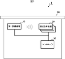
- FIG. 1 is a schematic diagram showing an example of the overall configuration of the equipment system 1 according to the first embodiment of the present disclosure.
- This equipment system 1 is a system in which equipment such as air conditioning equipment and lighting equipment is installed in the building BL, and the installation position is the first equipment equipment 10 which is the equipment whose installation position is known. It includes a second equipment 20 which is an unknown equipment and a controller 30.
- FIG. 1 shows a case where the equipment system 1 includes one first equipment 10 and a plurality of second equipment 20, but this is just an example, and the first equipment 10 is also included. You may have more than one.
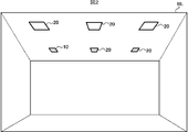
- Each equipment that is, the first equipment 10 and the second equipment 20, are installed on the ceiling in the building BL, for example, as shown in FIG.
- the first equipment 10 and the second equipment 20 are each installed according to the rules defined in the installation standards described later. As described above, the installation position of the first equipment 10 is known, while the installation position of the second equipment 20 is unknown.
- FIG. 2 also shows a case where one first equipment device 10 is installed, a plurality of them may be installed as described above.
- the controller 30 is an example of the position estimation device in the present disclosure, and is connected to the first equipment device 10 and the second equipment device 20 by wire or wirelessly. Prior to controlling the first equipment 10 and the second equipment 20, the controller 30 estimates the absolute position of the second equipment 20 whose installation position is unknown, as will be described later.
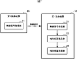
- FIG. 3 is a block diagram showing an example of the configuration of the first equipment device 10, the second equipment device 20, and the controller 30 according to the first embodiment of the present disclosure.
- the first equipment device 10 includes a wireless signal transmitting unit 11 which is an example of a wireless signal transmitting means.
- the wireless signal transmitting unit 11 transmits a wireless signal conforming to a wireless standard such as BLE (Bluetooth (registered trademark) Low Energy) or Wi-Fi.
- This radio signal includes a device ID for identifying the first equipment device 10. That is, the wireless signal transmitting unit 11 transmits a wireless signal including its own device ID in the floor.
- the first equipment 10 further includes a main functional unit (not shown).
- the first equipment 10 when the first equipment 10 is an air conditioner, the first equipment 10 further includes a configuration for realizing air conditioning functions such as cooling, heating, and dehumidification.
- the second equipment device 20 has a wireless signal receiving unit 21 which is an example of a wireless signal receiving means, a relative position estimating unit 22 which is an example of a relative position estimating means, and a relative position which is an example of a relative position transmitting means. It is provided with a transmission unit 23.
- the relative position estimation unit 22 is realized, for example, by the CPU (Central Processing Unit) using the RAM (RandomAccessMemory) as the work memory and appropriately executing the program stored in the ROM.
- the wireless signal receiving unit 21 receives the wireless signal transmitted from the first equipment 10. Then, the radio signal receiving unit 21 measures the radio wave strength and the phase difference of the received radio signal. Then, the wireless signal receiving unit 21 extracts the device ID included in the wireless signal and associates the device ID with the measurement result.
- the relative position estimation unit 22 estimates the relative position between the first equipment device 10 and the second equipment device 20 based on the radio wave intensity measured by the radio signal receiving unit 21 and the phase difference.
- the relative position estimation unit 22 calculates the distance between the first equipment device 10 and itself, that is, the second equipment device 20, according to the radio wave intensity measured by the radio signal receiving unit 21. Further, the relative position estimation unit 22 calculates the angle between the first equipment 10 and itself according to the phase difference measured by the radio signal receiving unit 21. Then, the relative position estimation unit 22 estimates its own relative position with respect to the first equipment 10 based on the calculated distance and angle.
- the relative position transmission unit 23 transmits information indicating the relative position estimated by the relative position estimation unit 22 to the controller 30.
- the relative position transmitting unit 23 adds the device ID of the first equipment device 10 extracted by the radio signal receiving unit 21 and its own device ID to the information indicating the relative position, and which first equipment It is possible to recognize the relative position between the device 10 and which second equipment device 20.
- the second equipment 20 further includes a main functional unit (not shown).
- the second equipment 20 when the second equipment 20 is an air conditioner, the second equipment 20 further includes a configuration for realizing air conditioning functions such as cooling, heating, and dehumidification.
- the controller 30 has a relative position receiving unit 31 which is an example of the relative position receiving means, a storage unit 32, an absolute position estimating unit 33 which is an example of the absolute position estimating means, and a display unit which is an example of the display means. It is equipped with 34.
- the absolute position estimation unit 33 is realized, for example, by the CPU using the RAM as a work memory and appropriately executing a program stored in the ROM.
- the relative position receiving unit 31 receives the information indicating the relative position transmitted from the second equipment 20.
- the relative position receiving unit 31 stores the received information in the storage unit 32.
- the storage unit 32 stores information indicating the relative position received by the relative position receiving unit 31. Further, the storage unit 32 stores in advance the absolute position of the first equipment device 10 whose installation position is known. Further, the storage unit 32 stores the equipment, that is, the installation standard applied when the first equipment 10 and the second equipment 20 are installed.
- This installation standard defines, for example, the installation interval X of equipment as shown in FIG. That is, it is stipulated that the first equipment 10 and the second equipment 20 are installed with an exact interval X.
- the installation standard defines, for example, the installation angle Y of the equipment as shown in FIG. That is, the first equipment 10 and the second equipment 20 are installed so as to accurately form an installation angle Y with respect to other equipment along the reference line L, for example, the nearest equipment. It is stipulated that it will be done.
- the storage unit 32 stores at least one such installation standard.
- the absolute position estimation unit 33 estimates the absolute position of the second equipment 20 with reference to the information stored in the storage unit 32.
- the absolute position estimation unit 33 is an absolute position between the first equipment equipment 10 and the second equipment equipment 20 indicated by the information received by the relative position reception unit 31 and the installation position of the first equipment equipment 10.
- the absolute position of the second equipment 20 is estimated based on the position and the installation standard defined for the installation of the equipment.
- the absolute position estimation unit 33 is based on the absolute position of the first equipment 10 whose installation position is known, and the installation position is unknown according to the relative position of the second equipment 20 with respect to the first equipment 10.
- the absolute position of the second equipment 20 is estimated.
- the absolute position estimation unit 33 improves the accuracy of the estimated absolute position by using the above-mentioned installation standard.
- the absolute position estimation unit 33 corrects the value of d to X.
- the absolute position estimation unit 33 corrects the value of d to 2X.
- the absolute position estimation unit 33 corrects the value of ⁇ to Y.
- the absolute position estimation unit 33 estimates the absolute position of the second equipment 20 while making such a correction. Further, the absolute position estimation unit 33 associates the estimated absolute position with the device ID of the second equipment device 20 and stores it in the storage unit 32.
- the display unit 34 displays the installation position of each equipment. For example, the display unit 34 superimposes an icon indicating the second equipment 20 on the corresponding position in the floor plan based on the absolute position of the second equipment 20 estimated by the absolute position estimation unit 33. indicate. In addition, the display unit 34 displays by superimposing an icon indicating the first equipment 10 on the corresponding position in the floor plan of the floor, based on the absolute position of the first equipment 10 whose installation position is known. You may try to do it.
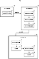
- FIG. 6 is a flowchart showing an example of the relative position estimation process and the absolute position estimation process according to the first embodiment of the present disclosure.
- One relative position estimation process is executed by each second equipment 20, and the other absolute position estimation process is executed by the controller 30.
- the first equipment 10 performs a relative position estimation process and a process of transmitting a radio signal in parallel with the absolute position estimation process.
- These processes are executed, for example, when the power is turned on to the first equipment 10, the second equipment 20, and the controller 30. In addition to this, when a predetermined operation is input to the controller 30, these processes may be executed.
- the second equipment 20 receives the radio signal transmitted from the first equipment 10 (step S101). That is, when the power is turned on, a wireless signal including the device ID is transmitted from the first equipment device 10 by the wireless signal transmitting unit 11. Therefore, the radio signal receiving unit 21 receives this radio signal.
- the second equipment 20 measures the radio field strength and the phase difference (step S102). That is, the radio signal receiving unit 21 measures the radio field strength and the phase difference of the radio signal received in step S101.
- the second equipment 20 estimates its own relative position with respect to the first equipment 10 (step S103). That is, the relative position estimation unit 22 estimates the relative position between the first equipment device 10 and the second equipment device 20 based on the radio wave intensity measured in step S102 and the phase difference. For example, the relative position estimation unit 22 calculates the distance between the first equipment 10 and itself according to the radio wave intensity measured by the radio signal receiving unit 21. Further, the relative position estimation unit 22 calculates the angle between the first equipment 10 and itself according to the phase difference measured by the radio signal receiving unit 21. Then, the relative position estimation unit 22 estimates its own relative position with respect to the first equipment 10 based on the calculated distance and angle.
- the second equipment 20 transmits the relative position information to the controller 30 (step S104). That is, the relative position transmission unit 23 transmits information indicating the relative position estimated in step S103 above to the controller 30.
- the relative position transmission unit 23 adds the device ID of the first equipment device 10 and its own device ID to the information indicating the relative position, and recognizes which facility device is the relative position. I am trying to do it.
- the controller 30 receives the relative position information (step S201). That is, the relative position receiving unit 31 receives the information indicating the relative position sent from the second equipment 20. Note that this step S201 is an example of a relative position receiving step.
- the controller 30 estimates the absolute position of the second equipment 20 based on the relative position of the second equipment 20, the known absolute position, and the installation standard (step S202). That is, the absolute position estimation unit 33 is an absolute position that is a relative position between the first equipment device 10 and the second equipment device 20 indicated by the information received in step S201 and an installation position of the first equipment device 10. The absolute position of the second equipment 20 is estimated based on the position and the installation standard defined for the installation of the equipment. For example, the absolute position estimation unit 33 is based on the absolute position of the first equipment 10 whose installation position is known, and the installation position is unknown according to the relative position of the second equipment 20 with respect to the first equipment 10. The absolute position of the second equipment 20 is estimated.
- the absolute position estimation unit 33 improves the accuracy of the absolute position by correcting, for example, the installation interval, the installation angle, and the like based on the installation standard stored in the storage unit 32. Note that this step S202 is an example of an absolute position estimation step.
- the controller 30 determines whether or not the estimation of the absolute position of all the second equipment 20 has been completed (step S203). When the controller 30 determines that the estimation for all the second equipment 20 has not been completed (step S203; No), the process returns to the above-mentioned step S201.
- step S204 the installation position of each equipment is displayed (step S204). That is, for example, the display unit 34 superimposes an icon indicating the second equipment 20 on the corresponding position of the floor plan based on the absolute position of the second equipment 20 estimated in step S202 above. indicate.
- the display unit 34 displays the icon indicating the first equipment 10 on the corresponding position of the floor plan based on the absolute position of the first equipment 10 whose installation position is known. You may.
- the installation position of the second equipment 20 can be estimated with higher accuracy.
- the first equipment 10 whose installation position is known transmits a radio signal
- the second equipment 20 whose installation position is unknown measures this radio signal and the first equipment equipment.
- the relative position of the second equipment 20 with respect to 10 is estimated and the information of the relative position is transmitted to the controller 30 has been described, the roles of the first equipment 10 and the second equipment 20 may be exchanged. ..
- the second equipment 20 includes the above-mentioned radio signal transmitting unit 11, while the first equipment 10 includes the above-mentioned radio signal receiving unit 21, relative position estimation unit 22, and the above-mentioned radio signal transmitting unit 11.
- the relative position transmission unit 23 may be provided. That is, the second equipment 20 whose installation position is unknown transmits a wireless signal, and the first equipment 10 whose installation position is known measures this wireless signal and the first equipment relative to the second equipment 20. The relative position of the device 10 is estimated, and the information on the relative position is transmitted to the controller 30.
- the controller 30 will receive information indicating the relative position between the first equipment 10 and the second equipment 20, and the relative position, the absolute position of the first equipment 10, and the installation standard are set. Based on this, the absolute position of the second equipment 20 will be estimated. In this case as well, the installation position of the second equipment 20 can be estimated with higher accuracy.
- the first equipment 10 has the same configuration as the first embodiment shown in FIG. 3 described above. That is, the first equipment device 10 includes a wireless signal transmitting unit 11 which is an example of the wireless signal transmitting means. Similar to the first embodiment, the wireless signal transmitting unit 11 transmits a wireless signal including its own device ID in the floor.
- the second equipment device 20 includes a wireless signal receiving unit 21 which is an example of the wireless signal receiving means, and a measurement information transmitting unit 24 which is an example of the measurement information transmitting means.
- the wireless signal receiving unit 21 has the same configuration as that of the first embodiment shown in FIG. That is, the radio signal receiving unit 21 measures the radio field strength and the phase difference of the received radio signal. Then, the wireless signal receiving unit 21 extracts the device ID included in the wireless signal and associates the device ID with the measurement result.
- the measurement information transmission unit 24 transmits the measurement information indicating the radio field strength and the phase difference measured by the radio signal reception unit 21 to the controller 30.
- the measurement information transmitting unit 24 adds the device ID of the first equipment device 10 extracted by the wireless signal receiving unit 21 and its own device ID to the measurement information, and which first equipment device 10 is used. , It is possible to recognize which second equipment 20 is the measurement information.
- the controller 30 is an example of the measurement information receiving unit 35 which is an example of the measurement information receiving means, the relative position estimation unit 36 which is an example of the relative position estimation means, the storage unit 32, and the absolute position estimation means. It includes an absolute position estimation unit 33 and a display unit 34 which is an example of display means.
- the storage unit 32, the absolute position estimation unit 33, and the display unit 34 have the same configuration as that of the first embodiment shown in FIG. Further, the relative position estimation unit 36 and the absolute position estimation unit 33 are realized, for example, by the CPU using the RAM as a work memory and appropriately executing a program stored in the ROM.
- the measurement information receiving unit 35 receives the measurement information transmitted from the second equipment 20.
- the measurement information receiving unit 35 supplies the received measurement information to the relative position estimation unit 36.
- the relative position estimation unit 36 determines the relative position between the first equipment device 10 and the second equipment device 20 based on the radio wave intensity and the phase difference indicated by the measurement information received by the measurement information receiving unit 35. presume. For example, the relative position estimation unit 36 calculates the distance between the first equipment device 10 and the second equipment device 20 according to the radio wave intensity. Further, the relative position estimation unit 36 calculates the angle between the first equipment device 10 and the second equipment device 20 according to the phase difference. Then, the relative position estimation unit 36 estimates the relative position of the second equipment 20 with respect to the first equipment 10 based on the calculated distance and angle. The relative position estimation unit 36 stores the estimated relative position in the storage unit 32.
- the storage unit 32 stores the relative position estimated by the relative position estimation unit 36 described above. Further, as in the first embodiment, the storage unit 32 stores the absolute position of the first equipment 10 whose installation position is known, and the installation standard.
- the absolute position estimation unit 33 estimates the absolute position of the second equipment 20 with reference to the information stored in the storage unit 32, as in the first embodiment.
- the absolute position estimation unit 33 has a relative position between the first equipment 10 and the second equipment 20 estimated by the relative position estimation unit 36, and an absolute position which is the installation position of the first equipment 10.
- the absolute position of the second equipment 20 is estimated based on the installation standard defined for the installation of the equipment. That is, the absolute position estimation unit 33 is based on the absolute position of the first equipment 10 whose installation position is known, and the installation position is unknown according to the relative position of the second equipment 20 with respect to the first equipment 10.
- the absolute position of the second equipment 20 is estimated. At that time, the absolute position estimation unit 33 improves the accuracy of the estimated absolute position by using the installation standard.
- the display unit 34 displays the installation position of each equipment as in the first embodiment. For example, the display unit 34 superimposes and displays an icon indicating the second equipment 20 on the corresponding position in the floor plan based on the absolute position of the second equipment 20 estimated by the absolute position estimation unit 33. .. In addition, the display unit 34 displays by superimposing an icon indicating the first equipment 10 on the corresponding position in the floor plan of the floor, based on the absolute position of the first equipment 10 whose installation position is known. You may try to do it.
- FIG. 9 is a flowchart showing an example of the signal measurement process and the absolute position estimation process according to the second embodiment of the present disclosure.
- the same reference numerals are given to the same processing contents as those in the first embodiment.
- One signal measurement process is executed by each second equipment 20, and the other absolute position estimation process is executed by the controller 30.
- the first equipment 10 performs a signal measurement process and a process of transmitting a wireless signal in parallel with the absolute position estimation process. These processes are executed, for example, when the power is turned on to the first equipment 10, the second equipment 20, and the controller 30. In addition to this, when a predetermined operation is input to the controller 30, these processes may be executed.
- the second equipment 20 receives the radio signal transmitted from the first equipment 10 (step S101). That is, when the power is turned on, a wireless signal including the device ID is transmitted from the first equipment device 10 by the wireless signal transmitting unit 11. Therefore, the radio signal receiving unit 21 receives this radio signal.
- the second equipment 20 measures the radio field strength and the phase difference (step S102). That is, the radio signal receiving unit 21 measures the radio field strength and the phase difference of the radio signal received in step S101.
- the second equipment 20 transmits relative position information to the controller 30 (step S111). That is, the measurement information transmission unit 24 transmits the measurement information indicating the radio field intensity and the phase difference measured in step S102 to the controller 30.
- the measurement information transmitting unit 24 adds the device ID of the first equipment device 10 extracted by the wireless signal receiving unit 21 and its own device ID to the measurement information, and which first equipment device 10 is used. , It is possible to recognize which second equipment 20 is the measurement information.
- the controller 30 receives the measurement information (step S211). That is, the relative position receiving unit 31 receives the measurement information sent from the second equipment device 20.
- the controller 30 estimates the relative position of the second equipment to the first equipment 10 (step S212). That is, the relative position estimation unit 36 determines the relative position between the first equipment device 10 and the second equipment device 20 based on the radio wave intensity and the phase difference indicated by the measurement information received in step S211. presume. For example, the relative position estimation unit 36 calculates the distance between the first equipment device 10 and the second equipment device 20 according to the radio wave intensity. Further, the relative position estimation unit 36 calculates the angle between the first equipment device 10 and the second equipment device 20 according to the phase difference. Then, the relative position estimation unit 36 estimates the relative position of the second equipment 20 with respect to the first equipment 10 based on the calculated distance and angle.
- the controller 30 estimates the absolute position of the second equipment 20 based on the relative position of the second equipment 20, the known absolute position, and the installation standard (step S202). That is, the absolute position estimation unit 33 determines the relative position between the first equipment 10 and the second equipment 20 estimated in step S212, and the absolute position which is the installation position of the first equipment 10. The absolute position of the second equipment 20 is estimated based on the installation standard defined for the installation of the equipment. For example, the absolute position estimation unit 33 is based on the absolute position of the first equipment 10 whose installation position is known, and the installation position is unknown according to the relative position of the second equipment 20 with respect to the first equipment 10. The absolute position of the second equipment 20 is estimated. At that time, the absolute position estimation unit 33 improves the accuracy of the absolute position by correcting, for example, the installation interval, the installation angle, and the like based on the installation standard stored in the storage unit 32.
- the controller 30 determines whether or not the estimation of the absolute position of all the second equipment 20 has been completed (step S203). When the controller 30 determines that the estimation for all the second equipment 20 has not been completed (step S203; No), the process returns to the above-mentioned step S211.
- step S204 the installation position of each equipment is displayed (step S204). That is, for example, the display unit 34 superimposes an icon indicating the second equipment 20 on the corresponding position of the floor plan based on the absolute position of the second equipment 20 estimated in step S202 above. indicate.
- the display unit 34 displays the icon indicating the first equipment 10 on the corresponding position of the floor plan based on the absolute position of the first equipment 10 whose installation position is known. You may.
- the measurement information about the radio signal transmitted from the first equipment 10 that is, the measurement information indicating the radio wave strength and the phase difference is obtained by the controller 30. Will be sent to each.
- the relative position of the second equipment 20 with respect to the first equipment 10 is estimated by the absolute position estimation process, and further, the relative position of the second equipment 20 and the absolute position of the first equipment 10 are installed.
- the absolute position of the second equipment 20 is estimated based on the standard. At this time, for example, the installation interval, the installation angle, and the like are corrected based on the installation standard, so that the accuracy of the absolute position is improved.
- the installation position of the second equipment 20 can be estimated with higher accuracy.
- the first equipment device 10 whose installation position is known transmits a wireless signal
- the second equipment device 20 whose installation position is unknown measures this wireless signal and measures it to the controller 30.
- the roles of the first equipment 10 and the second equipment 20 may be exchanged. That is, as in the modification of the first embodiment described above, the configurations of the first equipment 10 and the second equipment 20 are exchanged, and the second equipment 20 whose installation position is unknown transmits a wireless signal and is installed.
- the first equipment device 10 whose position is known measures this radio signal and transmits the measurement information to the controller 30.
- the controller 30 receives this measurement information, estimates the relative position of the first equipment 10 with respect to the second equipment 20, and determines the relative position, the absolute position of the first equipment 10, and the installation standard.
- the absolute position of the second equipment 20 will be estimated based on the above. In this case as well, the installation position of the second equipment 20 can be estimated with higher accuracy.
- FIG. 10 is a diagram showing an example of the overall configuration of the equipment system 2 and the configuration of the cloud server 40 according to another embodiment of the present disclosure.
- the equipment system 2 includes a first equipment 10, a second equipment 20, a controller 30, and a cloud server 40.
- the controller 30 and the cloud server 40 are connected to each other so as to be able to communicate with each other via the Internet N.
- the first equipment 10 and the second equipment 20 have the same configuration as the first embodiment shown in FIG. 3 described above.
- the controller 30 is configured to receive information indicating a relative position sent from the second equipment 20 and simply transmit the received information to the cloud server 40 as it is.
- the cloud server 40 has substantially the same configuration as that of the controller 30 according to the first embodiment shown in FIG. That is, the cloud server 40 includes a relative position receiving unit 31 which is an example of the relative position receiving means, a storage unit 32, an absolute position estimating unit 33 which is an example of the absolute position estimating means, and an absolute position transmitting unit 41. ing.
- the absolute position estimation unit 33 is realized, for example, by the CPU using the RAM as a work memory and appropriately executing a program stored in the ROM.
- the relative position receiving unit 31 receives the information indicating the relative position transmitted from the controller 30.
- the relative position receiving unit 31 stores the received information in the storage unit 32.
- the storage unit 32 stores information indicating the relative position received by the relative position receiving unit 31. Further, the storage unit 32 stores the absolute position of the first equipment 10 whose installation position is known and the installation standard.
- the absolute position estimation unit 33 estimates the absolute position of the second equipment 20 with reference to the information stored in the storage unit 32.
- the absolute position estimation unit 33 is an absolute position between the first equipment equipment 10 and the second equipment equipment 20 indicated by the information received by the relative position reception unit 31 and the installation position of the first equipment equipment 10.
- the absolute position of the second equipment 20 is estimated based on the position and the installation standard defined for the installation of the equipment. That is, the absolute position estimation unit 33 is based on the absolute position of the first equipment 10 whose installation position is known, and the installation position is unknown according to the relative position of the second equipment 20 with respect to the first equipment 10.
- the absolute position of the second equipment 20 is estimated. At that time, the absolute position estimation unit 33 improves the accuracy of the estimated absolute position by using the installation standard.
- the absolute position transmission unit 41 transmits the absolute position of the second equipment 20 estimated by the absolute position estimation unit 33 to the controller 30, the user's terminal, and the like.
- the absolute position transmission unit 41 may transmit the absolute position including the absolute position of the first equipment 10 whose installation position is known to the controller 30, the user's terminal, or the like.
- the absolute position of the second equipment 20 is based on the relative position of the second equipment 20, the absolute position of the first equipment 10, and the installation standard on the cloud server 40. Is estimated. At this time, for example, the installation interval, the installation angle, and the like are corrected based on the installation standard, so that the accuracy of the absolute position is improved. As a result, the installation position of the second equipment 20 can be estimated with higher accuracy.
- the cloud server 40 has substantially the same configuration as the controller 30 according to the first embodiment shown in FIG. 3 according to the first embodiment shown in FIG. 3 has been described with reference to FIG. 10, the cloud server 40 has the same configuration as that of the second embodiment shown in FIG. It may have substantially the same configuration as the controller 30.
- the program executed by the first equipment 10, the second equipment 20, the controller 30, and the cloud server 40 is a CD-ROM (Compact). It is also possible to store and distribute it in a computer-readable recording medium such as DiscReadOnlyMemory), DVD (DigitalVersatileDisc), MO (Magneto-OpticalDisk), USB memory, and memory card. Then, by installing such a program on a specific or general-purpose computer, the computer can be installed in the above-described first and second embodiments, and in other embodiments, the first equipment device 10, the second equipment device 20, and the controller 30. , And it is also possible to function as a cloud server 40.
- the above program may be stored in a disk device of a server device on a communication network such as the Internet, superimposed on a carrier wave, and downloaded to a computer, for example.
- the above-mentioned processing can also be achieved by starting and executing the program while transferring it via the communication network.
- the above-mentioned processing can also be achieved by executing all or a part of the program on the server device and executing the program while the computer sends and receives information about the processing via the communication network.
- the present disclosure can be suitably adopted for a position estimation device, an equipment system, a position estimation method, and a program capable of estimating the installation position of equipment with higher accuracy.
Landscapes
- Physics & Mathematics (AREA)
- Engineering & Computer Science (AREA)
- General Physics & Mathematics (AREA)
- Radar, Positioning & Navigation (AREA)
- Remote Sensing (AREA)
- Electromagnetism (AREA)
- Position Fixing By Use Of Radio Waves (AREA)
Priority Applications (4)
| Application Number | Priority Date | Filing Date | Title |
|---|---|---|---|
| US18/044,804 US12405348B2 (en) | 2020-11-24 | 2020-11-24 | Location estimation apparatus, facility device system, location estimation method, and recording medium |
| PCT/JP2020/043682 WO2022113172A1 (ja) | 2020-11-24 | 2020-11-24 | 位置推定装置、設備機器システム、位置推定方法、および、プログラム |
| JP2022564856A JP7399316B2 (ja) | 2020-11-24 | 2020-11-24 | 位置推定装置、設備機器システム、位置推定方法、および、プログラム |
| EP20963437.7A EP4253990A4 (en) | 2020-11-24 | 2020-11-24 | LOCATION ESTIMATION DEVICE, PLANT DEVICE SYSTEM, LOCATION ESTIMATION METHOD AND PROGRAM |
Applications Claiming Priority (1)
| Application Number | Priority Date | Filing Date | Title |
|---|---|---|---|
| PCT/JP2020/043682 WO2022113172A1 (ja) | 2020-11-24 | 2020-11-24 | 位置推定装置、設備機器システム、位置推定方法、および、プログラム |
Publications (1)
| Publication Number | Publication Date |
|---|---|
| WO2022113172A1 true WO2022113172A1 (ja) | 2022-06-02 |
Family
ID=81754107
Family Applications (1)
| Application Number | Title | Priority Date | Filing Date |
|---|---|---|---|
| PCT/JP2020/043682 Ceased WO2022113172A1 (ja) | 2020-11-24 | 2020-11-24 | 位置推定装置、設備機器システム、位置推定方法、および、プログラム |
Country Status (4)
| Country | Link |
|---|---|
| US (1) | US12405348B2 (https=) |
| EP (1) | EP4253990A4 (https=) |
| JP (1) | JP7399316B2 (https=) |
| WO (1) | WO2022113172A1 (https=) |
Citations (5)
| Publication number | Priority date | Publication date | Assignee | Title |
|---|---|---|---|---|
| JP2000013853A (ja) * | 1998-06-22 | 2000-01-14 | Mitsubishi Electric Corp | 無線通信システムおよび無線通信方法 |
| JP2010151807A (ja) * | 2008-11-19 | 2010-07-08 | Panasonic Corp | 無線測位装置及び座標構成方法 |
| JP2015519592A (ja) * | 2012-03-30 | 2015-07-09 | クゥアルコム・インコーポレイテッドQualcomm Incorporated | WiFiベースの屋内ポジショニングのためのマップ情報およびAP位置のマッシュアップ |
| WO2016125489A1 (ja) | 2015-02-03 | 2016-08-11 | 日本電気株式会社 | 位置推定装置、位置推定システム、位置推定方法および位置推定用記録媒体 |
| US20170171838A1 (en) * | 2014-08-29 | 2017-06-15 | Huawei Technologies Co., Ltd. | Resource allocation method, access point, and station |
Family Cites Families (17)
| Publication number | Priority date | Publication date | Assignee | Title |
|---|---|---|---|---|
| US7378980B2 (en) * | 2004-09-29 | 2008-05-27 | Siemens Building Technologies, Inc. | Triangulation of position for automated building control components |
| JP4254929B2 (ja) * | 2004-10-01 | 2009-04-15 | 三菱電機株式会社 | 位置決定方法およびシステム |
| JP4572698B2 (ja) | 2005-02-21 | 2010-11-04 | 日本電気株式会社 | 携帯端末装置、無線通信システム、位置情報算出方法及びプログラム |
| KR101033200B1 (ko) * | 2006-10-20 | 2011-05-06 | 주식회사 케이티 | Rfid와 통신망을 이용한 이동체 위치 확인 서비스시스템 및 그 방법 |
| JP5213132B2 (ja) * | 2008-11-25 | 2013-06-19 | 日本特殊陶業株式会社 | ガスセンサ制御装置及びガスセンサ制御方法 |
| KR101453651B1 (ko) * | 2012-02-11 | 2014-10-23 | 한성대학교 산학협력단 | 절대위치 및 상대위치 정보를 이용한 실내 자동 위치측정 시스템 및 방법 |
| GB2536722B (en) * | 2015-03-27 | 2021-02-03 | Arm Ip Ltd | Locating devices |
| US9736910B2 (en) * | 2015-09-30 | 2017-08-15 | Osram Sylvania Inc. | Lighting system that self detects the relative physical arrangement of its sources |
| SG11201811073TA (en) * | 2016-06-11 | 2019-01-30 | Enlighted Inc | Associating information with an asset or a physical space |
| KR101798167B1 (ko) * | 2017-01-16 | 2017-11-15 | 엘아이지넥스원 주식회사 | 무인 지상감시 센서노드 시스템 |
| JP6984817B2 (ja) | 2017-08-28 | 2021-12-22 | 国立大学法人岩手大学 | 無線通信装置を用いた位置推定方法、位置推定装置及び携帯通信装置 |
| US10346657B1 (en) * | 2018-01-10 | 2019-07-09 | Abl Ip Holding Llc | RFID system with antenna integrated in a luminaire |
| JP2020005024A (ja) * | 2018-06-25 | 2020-01-09 | ルネサスエレクトロニクス株式会社 | 端末認証装置、端末認証システム及び端末認証方法 |
| US11105886B2 (en) * | 2018-07-03 | 2021-08-31 | Abl Ip Holding Llc | Three-dimensional asset tracking using radio frequency-enabled nodes |
| WO2021079509A1 (ja) | 2019-10-25 | 2021-04-29 | 三菱電機株式会社 | 設備機器制御システム、情報端末、位置特定方法、および、プログラム |
| JP7292497B2 (ja) | 2020-03-27 | 2023-06-16 | 三菱電機株式会社 | 空調システム、操作端末及びプログラム |
| CN115699795A (zh) | 2020-06-17 | 2023-02-03 | 三菱电机株式会社 | 设备机器控制系统、用户终端、设备机器控制方法以及程序 |
-
2020
- 2020-11-24 WO PCT/JP2020/043682 patent/WO2022113172A1/ja not_active Ceased
- 2020-11-24 EP EP20963437.7A patent/EP4253990A4/en active Pending
- 2020-11-24 JP JP2022564856A patent/JP7399316B2/ja active Active
- 2020-11-24 US US18/044,804 patent/US12405348B2/en active Active
Patent Citations (5)
| Publication number | Priority date | Publication date | Assignee | Title |
|---|---|---|---|---|
| JP2000013853A (ja) * | 1998-06-22 | 2000-01-14 | Mitsubishi Electric Corp | 無線通信システムおよび無線通信方法 |
| JP2010151807A (ja) * | 2008-11-19 | 2010-07-08 | Panasonic Corp | 無線測位装置及び座標構成方法 |
| JP2015519592A (ja) * | 2012-03-30 | 2015-07-09 | クゥアルコム・インコーポレイテッドQualcomm Incorporated | WiFiベースの屋内ポジショニングのためのマップ情報およびAP位置のマッシュアップ |
| US20170171838A1 (en) * | 2014-08-29 | 2017-06-15 | Huawei Technologies Co., Ltd. | Resource allocation method, access point, and station |
| WO2016125489A1 (ja) | 2015-02-03 | 2016-08-11 | 日本電気株式会社 | 位置推定装置、位置推定システム、位置推定方法および位置推定用記録媒体 |
Non-Patent Citations (1)
| Title |
|---|
| See also references of EP4253990A4 |
Also Published As
| Publication number | Publication date |
|---|---|
| US20230366978A1 (en) | 2023-11-16 |
| JP7399316B2 (ja) | 2023-12-15 |
| EP4253990A1 (en) | 2023-10-04 |
| EP4253990A4 (en) | 2024-01-17 |
| JPWO2022113172A1 (https=) | 2022-06-02 |
| US12405348B2 (en) | 2025-09-02 |
Similar Documents
| Publication | Publication Date | Title |
|---|---|---|
| US7925384B2 (en) | Location-based provisioning of wireless control systems | |
| CN103354909B (zh) | 位置确定装置、方法、系统、空气调节系统以及照明系统 | |
| US11181603B2 (en) | Building automation system | |
| TW201814319A (zh) | 位置算出方法、距離算出方法、及信標 | |
| US10424932B2 (en) | Energy management controller, energy management method, and program | |
| JP6497210B2 (ja) | 位置推定システム | |
| JP4964311B2 (ja) | 電力管理システム | |
| JP4254929B2 (ja) | 位置決定方法およびシステム | |
| JP5699569B2 (ja) | 無線通信装置 | |
| JP7399316B2 (ja) | 位置推定装置、設備機器システム、位置推定方法、および、プログラム | |
| US20160219485A1 (en) | Method for connecting to access point in wlan system and electronic device thereof | |
| JP6602526B2 (ja) | 位置情報取得システム | |
| CN106030333B (zh) | 通信系统、有线通信装置、控制方法和控制程序 | |
| US11109341B2 (en) | Position estimation device and method in communication system | |
| EP3516461B1 (en) | A building automation system with servicing beacon | |
| JP2016156652A (ja) | 無線アクセスポイント装置、無線クライアント端末、サーバ装置、無線通信システムおよび位置推定方法 | |
| WO2016047091A1 (ja) | 無線通信システム、アクセスポイント、制御装置および位置算出方法 | |
| EP4050361A1 (en) | Facility equipment control system, information terminal, location identification method, and program | |
| JP7370173B2 (ja) | 空気調和機管理装置、空気調和システム、空気調和機管理方法およびプログラム | |
| CN115226026A (zh) | Ue定位方法、装置、设备和存储介质 | |
| JP6346078B2 (ja) | 電波強度特定装置、通信システム及び電波強度特定方法 | |
| JP2018198347A (ja) | 画像形成システム、画像形成装置、携帯端末、登録方法及びコンピュータプログラム | |
| KR20190101378A (ko) | 기존 검출 필드들을 사용하는 리버스 비콘 실내 위치 결정 시스템 | |
| HK40072320A (en) | Facility equipment control system, information terminal, location identification method, and program | |
| JP2017228933A (ja) | センサネットワークシステム |
Legal Events
| Date | Code | Title | Description |
|---|---|---|---|
| 121 | Ep: the epo has been informed by wipo that ep was designated in this application |
Ref document number: 20963437 Country of ref document: EP Kind code of ref document: A1 |
|
| ENP | Entry into the national phase |
Ref document number: 2022564856 Country of ref document: JP Kind code of ref document: A |
|
| NENP | Non-entry into the national phase |
Ref country code: DE |
|
| ENP | Entry into the national phase |
Ref document number: 2020963437 Country of ref document: EP Effective date: 20230626 |
|
| WWG | Wipo information: grant in national office |
Ref document number: 18044804 Country of ref document: US |
|
| WWW | Wipo information: withdrawn in national office |
Ref document number: 2020963437 Country of ref document: EP |