WO2022113172A1 - 位置推定装置、設備機器システム、位置推定方法、および、プログラム - Google Patents
位置推定装置、設備機器システム、位置推定方法、および、プログラム Download PDFInfo
- Publication number
- WO2022113172A1 WO2022113172A1 PCT/JP2020/043682 JP2020043682W WO2022113172A1 WO 2022113172 A1 WO2022113172 A1 WO 2022113172A1 JP 2020043682 W JP2020043682 W JP 2020043682W WO 2022113172 A1 WO2022113172 A1 WO 2022113172A1
- Authority
- WO
- WIPO (PCT)
- Prior art keywords
- equipment
- relative position
- installation
- absolute
- absolute position
- Prior art date
Links
- 238000000034 method Methods 0.000 title claims description 35
- 238000009434 installation Methods 0.000 claims abstract description 138
- 238000005259 measurement Methods 0.000 claims description 43
- 230000005540 biological transmission Effects 0.000 claims description 11
- 230000006870 function Effects 0.000 claims description 5
- 238000012545 processing Methods 0.000 description 7
- 238000010586 diagram Methods 0.000 description 6
- 238000004378 air conditioning Methods 0.000 description 4
- 238000012986 modification Methods 0.000 description 4
- 230000004048 modification Effects 0.000 description 4
- 238000004891 communication Methods 0.000 description 3
- 238000001816 cooling Methods 0.000 description 2
- 238000007791 dehumidification Methods 0.000 description 2
- 239000000284 extract Substances 0.000 description 2
- 238000010438 heat treatment Methods 0.000 description 2
- 238000012937 correction Methods 0.000 description 1
Images


Classifications
-
- G—PHYSICS
- G01—MEASURING; TESTING
- G01S—RADIO DIRECTION-FINDING; RADIO NAVIGATION; DETERMINING DISTANCE OR VELOCITY BY USE OF RADIO WAVES; LOCATING OR PRESENCE-DETECTING BY USE OF THE REFLECTION OR RERADIATION OF RADIO WAVES; ANALOGOUS ARRANGEMENTS USING OTHER WAVES
- G01S5/00—Position-fixing by co-ordinating two or more direction or position line determinations; Position-fixing by co-ordinating two or more distance determinations
- G01S5/02—Position-fixing by co-ordinating two or more direction or position line determinations; Position-fixing by co-ordinating two or more distance determinations using radio waves
- G01S5/0284—Relative positioning
-
- G—PHYSICS
- G01—MEASURING; TESTING
- G01S—RADIO DIRECTION-FINDING; RADIO NAVIGATION; DETERMINING DISTANCE OR VELOCITY BY USE OF RADIO WAVES; LOCATING OR PRESENCE-DETECTING BY USE OF THE REFLECTION OR RERADIATION OF RADIO WAVES; ANALOGOUS ARRANGEMENTS USING OTHER WAVES
- G01S5/00—Position-fixing by co-ordinating two or more direction or position line determinations; Position-fixing by co-ordinating two or more distance determinations
- G01S5/02—Position-fixing by co-ordinating two or more direction or position line determinations; Position-fixing by co-ordinating two or more distance determinations using radio waves
- G01S5/0269—Inferred or constrained positioning, e.g. employing knowledge of the physical or electromagnetic environment, state of motion or other contextual information to infer or constrain a position
-
- G—PHYSICS
- G01—MEASURING; TESTING
- G01S—RADIO DIRECTION-FINDING; RADIO NAVIGATION; DETERMINING DISTANCE OR VELOCITY BY USE OF RADIO WAVES; LOCATING OR PRESENCE-DETECTING BY USE OF THE REFLECTION OR RERADIATION OF RADIO WAVES; ANALOGOUS ARRANGEMENTS USING OTHER WAVES
- G01S5/00—Position-fixing by co-ordinating two or more direction or position line determinations; Position-fixing by co-ordinating two or more distance determinations
- G01S5/02—Position-fixing by co-ordinating two or more direction or position line determinations; Position-fixing by co-ordinating two or more distance determinations using radio waves
- G01S5/12—Position-fixing by co-ordinating two or more direction or position line determinations; Position-fixing by co-ordinating two or more distance determinations using radio waves by co-ordinating position lines of different shape, e.g. hyperbolic, circular, elliptical or radial
Definitions
- This disclosure relates to a position estimation device, an equipment system, a position estimation method, and a program.
- equipment such as air conditioners and lighting equipment have been installed on the floors of buildings such as office buildings and commercial buildings.
- Such equipment is controlled by a controller connected by wire or wirelessly so that the user on the floor can spend comfortably.
- the controller enhances the comfort of the user by appropriately controlling the equipment in the vicinity according to the position of the user existing on the floor. Therefore, the controller stores information about the position where the equipment is installed, that is, the installation position.
- the installation position was generally set manually by a worker who measured the equipment, but recently, the controller automatically sets the equipment.
- a mechanism for estimating the installation position has also been developed.
- Patent Document 1 discloses a technique of a position estimation device that estimates the position of a wireless device through transmission / reception of a wireless signal between wireless devices.
- This position estimator uses the distance between devices measured by one radio device to the other radio device, the measurement data regarding the certainty of the distance between the devices, and the distance between devices and the measurement data collected in the past. Based on this, the position of the wireless device is estimated.
- the position estimation device disclosed in Patent Document 1 utilizes the inter-device distance and measurement data collected in the past, and it is stated that the accuracy will be gradually improved in the process of repeatedly estimating the position of the wireless device. Intended. Therefore, when estimating the position of the wireless device for the first time, there is a concern that sufficient accuracy cannot be obtained. That is, in the position estimation device disclosed in Patent Document 1, it is necessary to repeat the position estimation a plurality of times in order to obtain sufficient accuracy, and it takes a long time to complete the position estimation. There was a problem.
- the present disclosure has been made to solve the above-mentioned problems, and is a position estimation device, an equipment system, a position estimation method, and a program capable of estimating the installation position of equipment with higher accuracy.
- the purpose is to provide.
- the position estimation device is A position estimation device that is communicably connected to two or more equipment including a first equipment whose installation position is known and a second equipment whose installation position is unknown.
- a relative position receiving means for receiving information indicating a relative position between the first equipment and the second equipment, which is sent from any of the equipment.
- Absolute position of the second equipment based on the relative position indicated by the information received by the relative position receiving means, the installation position of the first equipment, and the installation standard defined for the equipment.
- Absolute position estimation means to estimate To prepare for.
- the relative position receiving means receives the information indicating the relative position between the first equipment and the second equipment sent from any of the equipment, and the absolute position estimating means.
- the absolute position of the second equipment is estimated based on the relative position indicated by the received information, the installation position of the first equipment, and the installation standard defined for the equipment. As a result, the installation position of the equipment can be estimated with higher accuracy.
- Diagram to explain how equipment is installed The figure which shows an example of the structure of the 1st equipment, the 2nd equipment, and the controller which concerns on Embodiment 1 of this disclosure.
- Diagram for explaining the installation interval of equipment Diagram for explaining the installation angle of equipment
- a flowchart for explaining the relative position estimation process and the absolute position estimation process according to the first embodiment of the present disclosure The figure which shows an example of the structure of the 2nd equipment equipment which is the modification of Embodiment 1 and the 1st equipment equipment.
- a flowchart for explaining the signal measurement process and the absolute position estimation process according to the second embodiment of the present disclosure The figure which shows the whole structure of the equipment system which concerns on other embodiment of this disclosure, and an example of the structure of a cloud server.
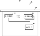
- FIG. 1 is a schematic diagram showing an example of the overall configuration of the equipment system 1 according to the first embodiment of the present disclosure.
- This equipment system 1 is a system in which equipment such as air conditioning equipment and lighting equipment is installed in the building BL, and the installation position is the first equipment equipment 10 which is the equipment whose installation position is known. It includes a second equipment 20 which is an unknown equipment and a controller 30.
- FIG. 1 shows a case where the equipment system 1 includes one first equipment 10 and a plurality of second equipment 20, but this is just an example, and the first equipment 10 is also included. You may have more than one.
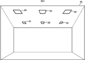
- Each equipment that is, the first equipment 10 and the second equipment 20, are installed on the ceiling in the building BL, for example, as shown in FIG.
- the first equipment 10 and the second equipment 20 are each installed according to the rules defined in the installation standards described later. As described above, the installation position of the first equipment 10 is known, while the installation position of the second equipment 20 is unknown.
- FIG. 2 also shows a case where one first equipment device 10 is installed, a plurality of them may be installed as described above.
- the controller 30 is an example of the position estimation device in the present disclosure, and is connected to the first equipment device 10 and the second equipment device 20 by wire or wirelessly. Prior to controlling the first equipment 10 and the second equipment 20, the controller 30 estimates the absolute position of the second equipment 20 whose installation position is unknown, as will be described later.
- FIG. 3 is a block diagram showing an example of the configuration of the first equipment device 10, the second equipment device 20, and the controller 30 according to the first embodiment of the present disclosure.
- the first equipment device 10 includes a wireless signal transmitting unit 11 which is an example of a wireless signal transmitting means.
- the wireless signal transmitting unit 11 transmits a wireless signal conforming to a wireless standard such as BLE (Bluetooth (registered trademark) Low Energy) or Wi-Fi.
- This radio signal includes a device ID for identifying the first equipment device 10. That is, the wireless signal transmitting unit 11 transmits a wireless signal including its own device ID in the floor.
- the first equipment 10 further includes a main functional unit (not shown).
- the first equipment 10 when the first equipment 10 is an air conditioner, the first equipment 10 further includes a configuration for realizing air conditioning functions such as cooling, heating, and dehumidification.
- the second equipment device 20 has a wireless signal receiving unit 21 which is an example of a wireless signal receiving means, a relative position estimating unit 22 which is an example of a relative position estimating means, and a relative position which is an example of a relative position transmitting means. It is provided with a transmission unit 23.
- the relative position estimation unit 22 is realized, for example, by the CPU (Central Processing Unit) using the RAM (RandomAccessMemory) as the work memory and appropriately executing the program stored in the ROM.
- the wireless signal receiving unit 21 receives the wireless signal transmitted from the first equipment 10. Then, the radio signal receiving unit 21 measures the radio wave strength and the phase difference of the received radio signal. Then, the wireless signal receiving unit 21 extracts the device ID included in the wireless signal and associates the device ID with the measurement result.
- the relative position estimation unit 22 estimates the relative position between the first equipment device 10 and the second equipment device 20 based on the radio wave intensity measured by the radio signal receiving unit 21 and the phase difference.
- the relative position estimation unit 22 calculates the distance between the first equipment device 10 and itself, that is, the second equipment device 20, according to the radio wave intensity measured by the radio signal receiving unit 21. Further, the relative position estimation unit 22 calculates the angle between the first equipment 10 and itself according to the phase difference measured by the radio signal receiving unit 21. Then, the relative position estimation unit 22 estimates its own relative position with respect to the first equipment 10 based on the calculated distance and angle.
- the relative position transmission unit 23 transmits information indicating the relative position estimated by the relative position estimation unit 22 to the controller 30.
- the relative position transmitting unit 23 adds the device ID of the first equipment device 10 extracted by the radio signal receiving unit 21 and its own device ID to the information indicating the relative position, and which first equipment It is possible to recognize the relative position between the device 10 and which second equipment device 20.
- the second equipment 20 further includes a main functional unit (not shown).
- the second equipment 20 when the second equipment 20 is an air conditioner, the second equipment 20 further includes a configuration for realizing air conditioning functions such as cooling, heating, and dehumidification.
- the controller 30 has a relative position receiving unit 31 which is an example of the relative position receiving means, a storage unit 32, an absolute position estimating unit 33 which is an example of the absolute position estimating means, and a display unit which is an example of the display means. It is equipped with 34.
- the absolute position estimation unit 33 is realized, for example, by the CPU using the RAM as a work memory and appropriately executing a program stored in the ROM.
- the relative position receiving unit 31 receives the information indicating the relative position transmitted from the second equipment 20.
- the relative position receiving unit 31 stores the received information in the storage unit 32.
- the storage unit 32 stores information indicating the relative position received by the relative position receiving unit 31. Further, the storage unit 32 stores in advance the absolute position of the first equipment device 10 whose installation position is known. Further, the storage unit 32 stores the equipment, that is, the installation standard applied when the first equipment 10 and the second equipment 20 are installed.
- This installation standard defines, for example, the installation interval X of equipment as shown in FIG. That is, it is stipulated that the first equipment 10 and the second equipment 20 are installed with an exact interval X.
- the installation standard defines, for example, the installation angle Y of the equipment as shown in FIG. That is, the first equipment 10 and the second equipment 20 are installed so as to accurately form an installation angle Y with respect to other equipment along the reference line L, for example, the nearest equipment. It is stipulated that it will be done.
- the storage unit 32 stores at least one such installation standard.
- the absolute position estimation unit 33 estimates the absolute position of the second equipment 20 with reference to the information stored in the storage unit 32.
- the absolute position estimation unit 33 is an absolute position between the first equipment equipment 10 and the second equipment equipment 20 indicated by the information received by the relative position reception unit 31 and the installation position of the first equipment equipment 10.
- the absolute position of the second equipment 20 is estimated based on the position and the installation standard defined for the installation of the equipment.
- the absolute position estimation unit 33 is based on the absolute position of the first equipment 10 whose installation position is known, and the installation position is unknown according to the relative position of the second equipment 20 with respect to the first equipment 10.
- the absolute position of the second equipment 20 is estimated.
- the absolute position estimation unit 33 improves the accuracy of the estimated absolute position by using the above-mentioned installation standard.
- the absolute position estimation unit 33 corrects the value of d to X.
- the absolute position estimation unit 33 corrects the value of d to 2X.
- the absolute position estimation unit 33 corrects the value of ⁇ to Y.
- the absolute position estimation unit 33 estimates the absolute position of the second equipment 20 while making such a correction. Further, the absolute position estimation unit 33 associates the estimated absolute position with the device ID of the second equipment device 20 and stores it in the storage unit 32.
- the display unit 34 displays the installation position of each equipment. For example, the display unit 34 superimposes an icon indicating the second equipment 20 on the corresponding position in the floor plan based on the absolute position of the second equipment 20 estimated by the absolute position estimation unit 33. indicate. In addition, the display unit 34 displays by superimposing an icon indicating the first equipment 10 on the corresponding position in the floor plan of the floor, based on the absolute position of the first equipment 10 whose installation position is known. You may try to do it.
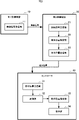
- FIG. 6 is a flowchart showing an example of the relative position estimation process and the absolute position estimation process according to the first embodiment of the present disclosure.
- One relative position estimation process is executed by each second equipment 20, and the other absolute position estimation process is executed by the controller 30.
- the first equipment 10 performs a relative position estimation process and a process of transmitting a radio signal in parallel with the absolute position estimation process.
- These processes are executed, for example, when the power is turned on to the first equipment 10, the second equipment 20, and the controller 30. In addition to this, when a predetermined operation is input to the controller 30, these processes may be executed.
- the second equipment 20 receives the radio signal transmitted from the first equipment 10 (step S101). That is, when the power is turned on, a wireless signal including the device ID is transmitted from the first equipment device 10 by the wireless signal transmitting unit 11. Therefore, the radio signal receiving unit 21 receives this radio signal.
- the second equipment 20 measures the radio field strength and the phase difference (step S102). That is, the radio signal receiving unit 21 measures the radio field strength and the phase difference of the radio signal received in step S101.
- the second equipment 20 estimates its own relative position with respect to the first equipment 10 (step S103). That is, the relative position estimation unit 22 estimates the relative position between the first equipment device 10 and the second equipment device 20 based on the radio wave intensity measured in step S102 and the phase difference. For example, the relative position estimation unit 22 calculates the distance between the first equipment 10 and itself according to the radio wave intensity measured by the radio signal receiving unit 21. Further, the relative position estimation unit 22 calculates the angle between the first equipment 10 and itself according to the phase difference measured by the radio signal receiving unit 21. Then, the relative position estimation unit 22 estimates its own relative position with respect to the first equipment 10 based on the calculated distance and angle.
- the second equipment 20 transmits the relative position information to the controller 30 (step S104). That is, the relative position transmission unit 23 transmits information indicating the relative position estimated in step S103 above to the controller 30.
- the relative position transmission unit 23 adds the device ID of the first equipment device 10 and its own device ID to the information indicating the relative position, and recognizes which facility device is the relative position. I am trying to do it.
- the controller 30 receives the relative position information (step S201). That is, the relative position receiving unit 31 receives the information indicating the relative position sent from the second equipment 20. Note that this step S201 is an example of a relative position receiving step.
- the controller 30 estimates the absolute position of the second equipment 20 based on the relative position of the second equipment 20, the known absolute position, and the installation standard (step S202). That is, the absolute position estimation unit 33 is an absolute position that is a relative position between the first equipment device 10 and the second equipment device 20 indicated by the information received in step S201 and an installation position of the first equipment device 10. The absolute position of the second equipment 20 is estimated based on the position and the installation standard defined for the installation of the equipment. For example, the absolute position estimation unit 33 is based on the absolute position of the first equipment 10 whose installation position is known, and the installation position is unknown according to the relative position of the second equipment 20 with respect to the first equipment 10. The absolute position of the second equipment 20 is estimated.
- the absolute position estimation unit 33 improves the accuracy of the absolute position by correcting, for example, the installation interval, the installation angle, and the like based on the installation standard stored in the storage unit 32. Note that this step S202 is an example of an absolute position estimation step.
- the controller 30 determines whether or not the estimation of the absolute position of all the second equipment 20 has been completed (step S203). When the controller 30 determines that the estimation for all the second equipment 20 has not been completed (step S203; No), the process returns to the above-mentioned step S201.
- step S204 the installation position of each equipment is displayed (step S204). That is, for example, the display unit 34 superimposes an icon indicating the second equipment 20 on the corresponding position of the floor plan based on the absolute position of the second equipment 20 estimated in step S202 above. indicate.
- the display unit 34 displays the icon indicating the first equipment 10 on the corresponding position of the floor plan based on the absolute position of the first equipment 10 whose installation position is known. You may.
- the installation position of the second equipment 20 can be estimated with higher accuracy.
- the first equipment 10 whose installation position is known transmits a radio signal
- the second equipment 20 whose installation position is unknown measures this radio signal and the first equipment equipment.
- the relative position of the second equipment 20 with respect to 10 is estimated and the information of the relative position is transmitted to the controller 30 has been described, the roles of the first equipment 10 and the second equipment 20 may be exchanged. ..
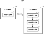
- the second equipment 20 includes the above-mentioned radio signal transmitting unit 11, while the first equipment 10 includes the above-mentioned radio signal receiving unit 21, relative position estimation unit 22, and the above-mentioned radio signal transmitting unit 11.
- the relative position transmission unit 23 may be provided. That is, the second equipment 20 whose installation position is unknown transmits a wireless signal, and the first equipment 10 whose installation position is known measures this wireless signal and the first equipment relative to the second equipment 20. The relative position of the device 10 is estimated, and the information on the relative position is transmitted to the controller 30.
- the controller 30 will receive information indicating the relative position between the first equipment 10 and the second equipment 20, and the relative position, the absolute position of the first equipment 10, and the installation standard are set. Based on this, the absolute position of the second equipment 20 will be estimated. In this case as well, the installation position of the second equipment 20 can be estimated with higher accuracy.
- the first equipment 10 has the same configuration as the first embodiment shown in FIG. 3 described above. That is, the first equipment device 10 includes a wireless signal transmitting unit 11 which is an example of the wireless signal transmitting means. Similar to the first embodiment, the wireless signal transmitting unit 11 transmits a wireless signal including its own device ID in the floor.
- the second equipment device 20 includes a wireless signal receiving unit 21 which is an example of the wireless signal receiving means, and a measurement information transmitting unit 24 which is an example of the measurement information transmitting means.
- the wireless signal receiving unit 21 has the same configuration as that of the first embodiment shown in FIG. That is, the radio signal receiving unit 21 measures the radio field strength and the phase difference of the received radio signal. Then, the wireless signal receiving unit 21 extracts the device ID included in the wireless signal and associates the device ID with the measurement result.
- the measurement information transmission unit 24 transmits the measurement information indicating the radio field strength and the phase difference measured by the radio signal reception unit 21 to the controller 30.
- the measurement information transmitting unit 24 adds the device ID of the first equipment device 10 extracted by the wireless signal receiving unit 21 and its own device ID to the measurement information, and which first equipment device 10 is used. , It is possible to recognize which second equipment 20 is the measurement information.
- the controller 30 is an example of the measurement information receiving unit 35 which is an example of the measurement information receiving means, the relative position estimation unit 36 which is an example of the relative position estimation means, the storage unit 32, and the absolute position estimation means. It includes an absolute position estimation unit 33 and a display unit 34 which is an example of display means.
- the storage unit 32, the absolute position estimation unit 33, and the display unit 34 have the same configuration as that of the first embodiment shown in FIG. Further, the relative position estimation unit 36 and the absolute position estimation unit 33 are realized, for example, by the CPU using the RAM as a work memory and appropriately executing a program stored in the ROM.
- the measurement information receiving unit 35 receives the measurement information transmitted from the second equipment 20.
- the measurement information receiving unit 35 supplies the received measurement information to the relative position estimation unit 36.
- the relative position estimation unit 36 determines the relative position between the first equipment device 10 and the second equipment device 20 based on the radio wave intensity and the phase difference indicated by the measurement information received by the measurement information receiving unit 35. presume. For example, the relative position estimation unit 36 calculates the distance between the first equipment device 10 and the second equipment device 20 according to the radio wave intensity. Further, the relative position estimation unit 36 calculates the angle between the first equipment device 10 and the second equipment device 20 according to the phase difference. Then, the relative position estimation unit 36 estimates the relative position of the second equipment 20 with respect to the first equipment 10 based on the calculated distance and angle. The relative position estimation unit 36 stores the estimated relative position in the storage unit 32.
- the storage unit 32 stores the relative position estimated by the relative position estimation unit 36 described above. Further, as in the first embodiment, the storage unit 32 stores the absolute position of the first equipment 10 whose installation position is known, and the installation standard.
- the absolute position estimation unit 33 estimates the absolute position of the second equipment 20 with reference to the information stored in the storage unit 32, as in the first embodiment.
- the absolute position estimation unit 33 has a relative position between the first equipment 10 and the second equipment 20 estimated by the relative position estimation unit 36, and an absolute position which is the installation position of the first equipment 10.
- the absolute position of the second equipment 20 is estimated based on the installation standard defined for the installation of the equipment. That is, the absolute position estimation unit 33 is based on the absolute position of the first equipment 10 whose installation position is known, and the installation position is unknown according to the relative position of the second equipment 20 with respect to the first equipment 10.
- the absolute position of the second equipment 20 is estimated. At that time, the absolute position estimation unit 33 improves the accuracy of the estimated absolute position by using the installation standard.
- the display unit 34 displays the installation position of each equipment as in the first embodiment. For example, the display unit 34 superimposes and displays an icon indicating the second equipment 20 on the corresponding position in the floor plan based on the absolute position of the second equipment 20 estimated by the absolute position estimation unit 33. .. In addition, the display unit 34 displays by superimposing an icon indicating the first equipment 10 on the corresponding position in the floor plan of the floor, based on the absolute position of the first equipment 10 whose installation position is known. You may try to do it.
- FIG. 9 is a flowchart showing an example of the signal measurement process and the absolute position estimation process according to the second embodiment of the present disclosure.
- the same reference numerals are given to the same processing contents as those in the first embodiment.
- One signal measurement process is executed by each second equipment 20, and the other absolute position estimation process is executed by the controller 30.
- the first equipment 10 performs a signal measurement process and a process of transmitting a wireless signal in parallel with the absolute position estimation process. These processes are executed, for example, when the power is turned on to the first equipment 10, the second equipment 20, and the controller 30. In addition to this, when a predetermined operation is input to the controller 30, these processes may be executed.
- the second equipment 20 receives the radio signal transmitted from the first equipment 10 (step S101). That is, when the power is turned on, a wireless signal including the device ID is transmitted from the first equipment device 10 by the wireless signal transmitting unit 11. Therefore, the radio signal receiving unit 21 receives this radio signal.
- the second equipment 20 measures the radio field strength and the phase difference (step S102). That is, the radio signal receiving unit 21 measures the radio field strength and the phase difference of the radio signal received in step S101.
- the second equipment 20 transmits relative position information to the controller 30 (step S111). That is, the measurement information transmission unit 24 transmits the measurement information indicating the radio field intensity and the phase difference measured in step S102 to the controller 30.
- the measurement information transmitting unit 24 adds the device ID of the first equipment device 10 extracted by the wireless signal receiving unit 21 and its own device ID to the measurement information, and which first equipment device 10 is used. , It is possible to recognize which second equipment 20 is the measurement information.
- the controller 30 receives the measurement information (step S211). That is, the relative position receiving unit 31 receives the measurement information sent from the second equipment device 20.
- the controller 30 estimates the relative position of the second equipment to the first equipment 10 (step S212). That is, the relative position estimation unit 36 determines the relative position between the first equipment device 10 and the second equipment device 20 based on the radio wave intensity and the phase difference indicated by the measurement information received in step S211. presume. For example, the relative position estimation unit 36 calculates the distance between the first equipment device 10 and the second equipment device 20 according to the radio wave intensity. Further, the relative position estimation unit 36 calculates the angle between the first equipment device 10 and the second equipment device 20 according to the phase difference. Then, the relative position estimation unit 36 estimates the relative position of the second equipment 20 with respect to the first equipment 10 based on the calculated distance and angle.
- the controller 30 estimates the absolute position of the second equipment 20 based on the relative position of the second equipment 20, the known absolute position, and the installation standard (step S202). That is, the absolute position estimation unit 33 determines the relative position between the first equipment 10 and the second equipment 20 estimated in step S212, and the absolute position which is the installation position of the first equipment 10. The absolute position of the second equipment 20 is estimated based on the installation standard defined for the installation of the equipment. For example, the absolute position estimation unit 33 is based on the absolute position of the first equipment 10 whose installation position is known, and the installation position is unknown according to the relative position of the second equipment 20 with respect to the first equipment 10. The absolute position of the second equipment 20 is estimated. At that time, the absolute position estimation unit 33 improves the accuracy of the absolute position by correcting, for example, the installation interval, the installation angle, and the like based on the installation standard stored in the storage unit 32.
- the controller 30 determines whether or not the estimation of the absolute position of all the second equipment 20 has been completed (step S203). When the controller 30 determines that the estimation for all the second equipment 20 has not been completed (step S203; No), the process returns to the above-mentioned step S211.
- step S204 the installation position of each equipment is displayed (step S204). That is, for example, the display unit 34 superimposes an icon indicating the second equipment 20 on the corresponding position of the floor plan based on the absolute position of the second equipment 20 estimated in step S202 above. indicate.
- the display unit 34 displays the icon indicating the first equipment 10 on the corresponding position of the floor plan based on the absolute position of the first equipment 10 whose installation position is known. You may.
- the measurement information about the radio signal transmitted from the first equipment 10 that is, the measurement information indicating the radio wave strength and the phase difference is obtained by the controller 30. Will be sent to each.
- the relative position of the second equipment 20 with respect to the first equipment 10 is estimated by the absolute position estimation process, and further, the relative position of the second equipment 20 and the absolute position of the first equipment 10 are installed.
- the absolute position of the second equipment 20 is estimated based on the standard. At this time, for example, the installation interval, the installation angle, and the like are corrected based on the installation standard, so that the accuracy of the absolute position is improved.
- the installation position of the second equipment 20 can be estimated with higher accuracy.
- the first equipment device 10 whose installation position is known transmits a wireless signal
- the second equipment device 20 whose installation position is unknown measures this wireless signal and measures it to the controller 30.
- the roles of the first equipment 10 and the second equipment 20 may be exchanged. That is, as in the modification of the first embodiment described above, the configurations of the first equipment 10 and the second equipment 20 are exchanged, and the second equipment 20 whose installation position is unknown transmits a wireless signal and is installed.
- the first equipment device 10 whose position is known measures this radio signal and transmits the measurement information to the controller 30.
- the controller 30 receives this measurement information, estimates the relative position of the first equipment 10 with respect to the second equipment 20, and determines the relative position, the absolute position of the first equipment 10, and the installation standard.
- the absolute position of the second equipment 20 will be estimated based on the above. In this case as well, the installation position of the second equipment 20 can be estimated with higher accuracy.
- FIG. 10 is a diagram showing an example of the overall configuration of the equipment system 2 and the configuration of the cloud server 40 according to another embodiment of the present disclosure.
- the equipment system 2 includes a first equipment 10, a second equipment 20, a controller 30, and a cloud server 40.
- the controller 30 and the cloud server 40 are connected to each other so as to be able to communicate with each other via the Internet N.
- the first equipment 10 and the second equipment 20 have the same configuration as the first embodiment shown in FIG. 3 described above.
- the controller 30 is configured to receive information indicating a relative position sent from the second equipment 20 and simply transmit the received information to the cloud server 40 as it is.
- the cloud server 40 has substantially the same configuration as that of the controller 30 according to the first embodiment shown in FIG. That is, the cloud server 40 includes a relative position receiving unit 31 which is an example of the relative position receiving means, a storage unit 32, an absolute position estimating unit 33 which is an example of the absolute position estimating means, and an absolute position transmitting unit 41. ing.
- the absolute position estimation unit 33 is realized, for example, by the CPU using the RAM as a work memory and appropriately executing a program stored in the ROM.
- the relative position receiving unit 31 receives the information indicating the relative position transmitted from the controller 30.
- the relative position receiving unit 31 stores the received information in the storage unit 32.
- the storage unit 32 stores information indicating the relative position received by the relative position receiving unit 31. Further, the storage unit 32 stores the absolute position of the first equipment 10 whose installation position is known and the installation standard.
- the absolute position estimation unit 33 estimates the absolute position of the second equipment 20 with reference to the information stored in the storage unit 32.
- the absolute position estimation unit 33 is an absolute position between the first equipment equipment 10 and the second equipment equipment 20 indicated by the information received by the relative position reception unit 31 and the installation position of the first equipment equipment 10.
- the absolute position of the second equipment 20 is estimated based on the position and the installation standard defined for the installation of the equipment. That is, the absolute position estimation unit 33 is based on the absolute position of the first equipment 10 whose installation position is known, and the installation position is unknown according to the relative position of the second equipment 20 with respect to the first equipment 10.
- the absolute position of the second equipment 20 is estimated. At that time, the absolute position estimation unit 33 improves the accuracy of the estimated absolute position by using the installation standard.
- the absolute position transmission unit 41 transmits the absolute position of the second equipment 20 estimated by the absolute position estimation unit 33 to the controller 30, the user's terminal, and the like.
- the absolute position transmission unit 41 may transmit the absolute position including the absolute position of the first equipment 10 whose installation position is known to the controller 30, the user's terminal, or the like.
- the absolute position of the second equipment 20 is based on the relative position of the second equipment 20, the absolute position of the first equipment 10, and the installation standard on the cloud server 40. Is estimated. At this time, for example, the installation interval, the installation angle, and the like are corrected based on the installation standard, so that the accuracy of the absolute position is improved. As a result, the installation position of the second equipment 20 can be estimated with higher accuracy.
- the cloud server 40 has substantially the same configuration as the controller 30 according to the first embodiment shown in FIG. 3 according to the first embodiment shown in FIG. 3 has been described with reference to FIG. 10, the cloud server 40 has the same configuration as that of the second embodiment shown in FIG. It may have substantially the same configuration as the controller 30.
- the program executed by the first equipment 10, the second equipment 20, the controller 30, and the cloud server 40 is a CD-ROM (Compact). It is also possible to store and distribute it in a computer-readable recording medium such as DiscReadOnlyMemory), DVD (DigitalVersatileDisc), MO (Magneto-OpticalDisk), USB memory, and memory card. Then, by installing such a program on a specific or general-purpose computer, the computer can be installed in the above-described first and second embodiments, and in other embodiments, the first equipment device 10, the second equipment device 20, and the controller 30. , And it is also possible to function as a cloud server 40.
- the above program may be stored in a disk device of a server device on a communication network such as the Internet, superimposed on a carrier wave, and downloaded to a computer, for example.
- the above-mentioned processing can also be achieved by starting and executing the program while transferring it via the communication network.
- the above-mentioned processing can also be achieved by executing all or a part of the program on the server device and executing the program while the computer sends and receives information about the processing via the communication network.
- the present disclosure can be suitably adopted for a position estimation device, an equipment system, a position estimation method, and a program capable of estimating the installation position of equipment with higher accuracy.
Abstract
設置位置が未知の第2設備機器(20)では、相対位置推定部(22)が、設置位置が既知の第1設備機器(10)から発信される無線信号を計測して第1設備機器(10)と第2設備機器(20)との間の相対位置を推定する。コントローラ(30)では、相対位置受信部(31)が、第2設備機器(20)から送られる相対位置を示す情報を受信する。そして、絶対位置推定部(33)は、相対位置受信部(31)が受信した情報が示す相対位置と、第1設備機器(10)の設置位置と、設備機器(10,20)に定められた設置規格とに基づいて、第2設備機器(20)の絶対位置を推定する。
Description
本開示は、位置推定装置、設備機器システム、位置推定方法、および、プログラムに関する。
従来より、オフィスビル、商業ビル等に代表される建物のフロア内には、例えば、空調機、及び、照明機器等の設備機器が設置されている。このような設備機器は、有線、若しくは、無線で接続されたコントローラによって、フロア内の利用者が快適に過ごせるように制御される。例えば、コントローラは、フロア内に存在する利用者の位置に応じて、近傍の設備機器を適切に制御することで、利用者の快適性を高めている。そのために、コントローラは、設備機器が設置されている位置、つまり、設置位置についての情報を記憶している。なお、このような設置位置は、従来であれば、設備機器について計測を行った作業者によって手動で設定されるのが一般的であったが、最近では、コントローラが自動的に、設備機器の設置位置を推定する仕組みも開発されている。
例えば、特許文献1には、無線装置間における無線信号の送受信を通じて、無線装置の位置を推定する位置推定装置の技術が開示されている。この位置推定装置は、一方の無線装置が測定した他方の無線装置との間の装置間距離と、この装置間距離の確からしさに関する測定データと、過去に収集した装置間距離および測定データとに基づいて、無線装置の位置を推定している。
しかしながら、特許文献1に開示された位置推定装置は、過去に収集した装置間距離および測定データを活用しており、繰り返し無線装置の位置を推定する過程において、徐々に精度を上げていくことを意図している。そのため、最初に無線装置の位置を推定する際には、十分な精度を得られないことが懸念される。つまり、特許文献1に開示された位置推定装置では、十分な精度を得るために、複数回に亘って位置の推定を繰り返す必要があり、位置の推定を終えるまでに長時間を要してしまうという課題があった。
このため、長時間を要することなく、設備機器の設置位置をより高精度に推定する技術が求められていた。
本開示は、上述のような課題を解決するためになされたものであり、設備機器の設置位置をより高精度に推定することのできる位置推定装置、設備機器システム、位置推定方法、および、プログラムを提供することを目的とする。
上記目的を達成するため、本開示に係る位置推定装置は、
設置位置が既知の第1設備機器、及び、設置位置が未知の第2設備機器を含む2台以上の設備機器と通信可能に接続された位置推定装置であって、
前記設備機器の何れかから送られる、前記第1設備機器と前記第2設備機器との間の相対位置を示す情報を受信する相対位置受信手段と、
前記相対位置受信手段が受信した前記情報が示す前記相対位置と、前記第1設備機器の前記設置位置と、前記設備機器に定められた設置規格とに基づいて、前記第2設備機器の絶対位置を推定する絶対位置推定手段と、
を備える。
設置位置が既知の第1設備機器、及び、設置位置が未知の第2設備機器を含む2台以上の設備機器と通信可能に接続された位置推定装置であって、
前記設備機器の何れかから送られる、前記第1設備機器と前記第2設備機器との間の相対位置を示す情報を受信する相対位置受信手段と、
前記相対位置受信手段が受信した前記情報が示す前記相対位置と、前記第1設備機器の前記設置位置と、前記設備機器に定められた設置規格とに基づいて、前記第2設備機器の絶対位置を推定する絶対位置推定手段と、
を備える。
本開示に係る位置推定装置では、相対位置受信手段が、設備機器の何れかから送られる、第1設備機器と第2設備機器との間の相対位置を示す情報を受信し、絶対位置推定手段が、受信した情報が示す相対位置と、第1設備機器の設置位置と、設備機器に定められた設置規格とに基づいて、第2設備機器の絶対位置を推定する。この結果、設備機器の設置位置をより高精度に推定することができる。
以下、本開示の実施形態について、図面を参照しながら詳細に説明する。なお、図中同一または相当部分には同一符号を付す。以下では、設備機器システムの一例として、空調機器、照明機器等の設備機器が建物内に設置された設備機器システムについて説明するが、設備機器の種類は任意であり、他の種類の機器が設置された設備機器システムにおいても同様に本開示を適用することができる。すなわち、以下に説明する実施形態は説明のためのものであり、本開示の範囲を制限するものではない。従って、当業者であればこれらの各要素または全要素をこれと均等なものに置換した実施形態を採用することが可能であるが、これらの実施形態も本開示の範囲に含まれる。つまり、本開示は、以下に説明する実施形態に限定されるものではなく、本開示の趣旨を逸脱しない範囲で種々に変形することが可能である。
(実施形態1)
図1は、本開示の実施形態1に係る設備機器システム1の全体構成の一例を示す模式図である。この設備機器システム1は、建物BL内に、例えば、空調機器、照明機器等の設備機器が設置されたシステムであり、設置位置が既知の設備機器である第1設備機器10と、設置位置が未知の設備機器である第2設備機器20と、コントローラ30とを備えている。なお、図1では、設備機器システム1が、1つの第1設備機器10と複数の第2設備機器20を備えている場合を示しているが、一例であり、第1設備機器10の方も複数備えていてもよい。
図1は、本開示の実施形態1に係る設備機器システム1の全体構成の一例を示す模式図である。この設備機器システム1は、建物BL内に、例えば、空調機器、照明機器等の設備機器が設置されたシステムであり、設置位置が既知の設備機器である第1設備機器10と、設置位置が未知の設備機器である第2設備機器20と、コントローラ30とを備えている。なお、図1では、設備機器システム1が、1つの第1設備機器10と複数の第2設備機器20を備えている場合を示しているが、一例であり、第1設備機器10の方も複数備えていてもよい。
各設備機器、つまり、第1設備機器10、及び、第2設備機器20は、例えば、図2に示すように、建物BL内の天井にそれぞれ設置されている。これら第1設備機器10、及び、第2設備機器20は、後述する設置規格に定められたルールに従って、それぞれ設置されている。上述したように、第1設備機器10の方は、設置位置が既知であり、一方、第2設備機器20の方は、設置位置が未知となっている。なお、図2においても、1つの第1設備機器10が設置されている場合を示しているが、上述したように、複数設置されていてもよい。
図1に戻って、コントローラ30は、本開示における位置推定装置の一例であり、第1設備機器10、及び、第2設備機器20と、有線、若しくは、無線にて接続されている。コントローラ30は、第1設備機器10、及び、第2設備機器20を制御するのに先だって、後述するように、設置位置が未知の第2設備機器20の絶対位置を推定する。
以下、設備機器システム1の詳細について、図3を参照してそれぞれ説明する。図3は、本開示の実施形態1に係る第1設備機器10、第2設備機器20、並びに、コントローラ30の構成の一例を示すブロック図である。
まず、第1設備機器10は、無線信号発信手段の一例である無線信号発信部11を備えている。
無線信号発信部11は、例えば、BLE(Bluetooth(登録商標) Low Energy )、Wi-Fi等の無線規格に沿った無線信号を発信する。この無線信号には、第1設備機器10を識別するための機器IDが含まれている。つまり、無線信号発信部11は、自身の機器IDを含む無線信号をフロア内に送信する。
この他にも、第1設備機器10は、図示せぬ主機能部を更に備えている。例えば、第1設備機器10が空調機である場合、第1設備機器10は、冷房、暖房、および、除湿などの空調機能を実現するための構成を更に備えている。
続いて、第2設備機器20は、無線信号受信手段の一例である無線信号受信部21と、相対位置推定手段の一例である相対位置推定部22と、相対位置送信手段の一例である相対位置送信部23とを備えている。なお、相対位置推定部22は、例えば、CPU(Central Processing Unit)が、RAM(Random Access Memory)をワークメモリとして用い、ROMに記憶されているプログラムを適宜実行することにより実現される。
無線信号受信部21は、第1設備機器10から発信された無線信号を受信する。そして、無線信号受信部21は、受信した無線信号について、電波強度、及び、位相差を計測する。そして、無線信号受信部21は、無線信号に含まれる機器IDを抽出し、この機器IDと計測結果とを紐付ける。
相対位置推定部22は、上記の無線信号受信部21が計測した電波強度、及び、位相差に基づいて、第1設備機器10と第2設備機器20との間の相対位置を推定する。
例えば、相対位置推定部22は、無線信号受信部21が計測した電波強度に応じて、第1設備機器10と自身、つまり、第2設備機器20との距離を算出する。また、相対位置推定部22は、無線信号受信部21が計測した位相差に応じて、第1設備機器10と自身との角度を算出する。そして、相対位置推定部22は、算出した距離、及び、角度に基づいて、第1設備機器10に対する自身の相対位置を推定する。
相対位置送信部23は、上記の相対位置推定部22が推定した相対位置を示す情報をコントローラ30へ送信する。なお、相対位置送信部23は、相対位置を示す情報内に、無線信号受信部21が抽出した第1設備機器10の機器IDと、自身の機器IDとを付加しておき、どの第1設備機器10と、どの第2設備機器20との間の相対位置であるのかを認識できるようにしている。
この他にも、第2設備機器20は、図示せぬ主機能部を更に備えている。例えば、第2設備機器20が空調機である場合、第2設備機器20は、冷房、暖房、および、除湿などの空調機能を実現するための構成を更に備えている。
続いて、コントローラ30は、相対位置受信手段の一例である相対位置受信部31と、記憶部32と、絶対位置推定手段の一例である絶対位置推定部33と、表示手段の一例である表示部34とを備えている。なお、絶対位置推定部33は、例えば、CPUが、RAMをワークメモリとして用い、ROMに記憶されているプログラムを適宜実行することにより実現される。
相対位置受信部31は、第2設備機器20から送信された相対位置を示す情報を受信する。相対位置受信部31は、受信した情報を記憶部32に記憶させる。
記憶部32は、上記の相対位置受信部31が受信した相対位置を示す情報を記憶する。また、記憶部32は、設置位置が既知である第1設備機器10の絶対位置を予め記憶している。更に、記憶部32は、設備機器、つまり、第1設備機器10、及び、第2設備機器20がそれぞれ設置される際に適用される設置規格を記憶する。
この設置規格には、例えば、図4に示すように、設備機器の設置間隔Xが規定されている。つまり、第1設備機器10、及び、第2設備機器20には、正確に設置間隔Xを空けて設置されることが規定されている。
また、設置規格には、例えば、図5に示すように、設備機器の設置角度Yが規定されている。つまり、第1設備機器10、及び、第2設備機器20には、基準線Lに沿った他の設備機器、一例として、直近の設備機器に対して、正確に設置角度Yを成すように設置されることが規定されている。
これらの設置規格は、一例であり、他の内容が規定されていてもよい。そして、記憶部32は、このような設置規格を少なくとも1つ記憶している。
図3に戻って、絶対位置推定部33は、記憶部32に記憶された情報を参照して、第2設備機器20の絶対位置を推定する。例えば、絶対位置推定部33は、相対位置受信部31が受信した情報が示す第1設備機器10と第2設備機器20との間の相対位置と、第1設備機器10の設置位置である絶対位置と、設備機器の設置について定められた設置規格とに基づいて、第2設備機器20の絶対位置を推定する。
すなわち、絶対位置推定部33は、設置位置が既知である第1設備機器10の絶対位置を基準とし、この第1設備機器10に対する第2設備機器20の相対位置に従って、設置位置が未知である第2設備機器20の絶対位置を推定する。その際、絶対位置推定部33は、上述した設置規格を用いて、推定される絶対位置の精度を向上させる。
例えば、設置規格に、上述した図4に示すような設置間隔Xが規定されている場合において、推定される設置間距離dが、X/2≦d<3X/2を満たしている場合に、絶対位置推定部33は、このdの値をXに補正する。同様に、推定される設置間距離dが、3X/2≦d<5X/2を満たしている場合に、絶対位置推定部33は、このdの値を2Xに補正する。
また、設置規格に、上述した図5に示すような設置角度Yが規定されている場合において、推定される相対角度θが、Y-π/2≦θ<Y+π/2を満たしている場合に、絶対位置推定部33は、このθの値をYに補正する。
絶対位置推定部33は、このような補正を行いつつ、第2設備機器20の絶対位置を推定する。また、絶対位置推定部33は、推定した絶対位置を、第2設備機器20の機器IDと紐付けて、記憶部32に記憶させる。
表示部34は、各設備機器の設置位置をそれぞれ表示する。例えば、表示部34は、上記の絶対位置推定部33が推定した第2設備機器20の絶対位置に基づいて、フロアの間取り図における対応位置に、第2設備機器20を示すアイコンを重畳させて表示する。なお、表示部34は、設置位置が既知の第1設備機器10の絶対位置に基づいて、同様に、フロアの間取り図における対応位置に、第1設備機器10を示すアイコンを更に重畳させて表示するようにしてもよい。
以下、このような構成の設備機器システム1の動作について、図6を参照して説明する。図6は、本開示の実施形態1に係る相対位置推定処理、及び、絶対位置推定処理の一例を示すフローチャートである。一方の相対位置推定処理は、各第2設備機器20にてそれぞれ実行され、他方の絶対位置推定処理は、コントローラ30にて実行される。なお、図示していないが、第1設備機器10では、相対位置推定処理、及び、絶対位置推定処理と並行して無線信号を送信する処理が行われるものとする。これらの処理は、例えば、第1設備機器10、第2設備機器20、並びに、コントローラ30に電源が投入された際に実行させる。この他にも、コントローラ30に対して、予め定められた操作が入力された場合に、これらの処理が実行されるようにしてもよい。
まず、第2設備機器20は、第1設備機器10から発信された無線信号を受信する(ステップS101)。すなわち、電源投入に伴って、第1設備機器10からは、無線信号発信部11により、機器IDを含む無線信号が送られてくる。そのため、無線信号受信部21は、この無線信号を受信する。
第2設備機器20は、電波強度、及び、位相差を計測する(ステップS102)。すなわち、無線信号受信部21は、上記のステップS101にて受信した無線信号について、電波強度、及び、位相差を計測する。
第2設備機器20は、第1設備機器10に対する自身の相対位置を推定する(ステップS103)。すなわち、相対位置推定部22は、上記のステップS102にて計測した電波強度、及び、位相差に基づいて、第1設備機器10と第2設備機器20との間の相対位置を推定する。例えば、相対位置推定部22は、無線信号受信部21が計測した電波強度に応じて、第1設備機器10と自身との距離を算出する。また、相対位置推定部22は、無線信号受信部21が計測した位相差に応じて、第1設備機器10と自身との角度を算出する。そして、相対位置推定部22は、算出した距離、及び、角度に基づいて、第1設備機器10に対する自身の相対位置を推定する。
第2設備機器20は、相対位置の情報をコントローラ30へ送信する(ステップS104)。すなわち、相対位置送信部23は、上記のステップS103にて推定した相対位置を示す情報をコントローラ30へ送信する。なお、相対位置送信部23は、相対位置を示す情報内に、第1設備機器10の機器IDと、自身の機器IDとを付加しておき、どの設備機器間の相対位置であるのかを認識できるようにしている。
一方、コントローラ30は、相対位置の情報を受信する(ステップS201)。すなわち、相対位置受信部31は、第2設備機器20から送られた相対位置を示す情報を受信する。なお、このステップS201が、相対位置受信ステップの一例である。
コントローラ30は、第2設備機器20の相対位置、既知の絶対位置、並びに、設置規格に基づいて、第2設備機器20の絶対位置を推定する(ステップS202)。すなわち、絶対位置推定部33は、上記のステップS201にて受信した情報が示す第1設備機器10と第2設備機器20との間の相対位置と、第1設備機器10の設置位置である絶対位置と、設備機器の設置について定められた設置規格とに基づいて、第2設備機器20の絶対位置を推定する。例えば、絶対位置推定部33は、設置位置が既知である第1設備機器10の絶対位置を基準とし、この第1設備機器10に対する第2設備機器20の相対位置に従って、設置位置が未知である第2設備機器20の絶対位置を推定する。その際、絶対位置推定部33は、記憶部32に記憶されている設置規格に基づいて、例えば、設置間隔、設置角度等を補正することで、絶対位置の精度を向上させる。なお、このステップS202が、絶対位置推定ステップの一例である。
コントローラ30は、全ての第2設備機器20について、絶対位置の推定が完了したか否かを判別する(ステップS203)。コントローラ30は、全ての第2設備機器20についての推定が完了していないと判別すると(ステップS203;No)、上述したステップS201に処理を戻す。
一方、全ての第2設備機器20についての推定が完了したと判別した場合(ステップS203;Yes)に、各設備機器の設置位置をそれぞれ表示する(ステップS204)。すなわち、表示部34は、例えば、上記のステップS202にて推定した第2設備機器20の絶対位置に基づいて、フロアの間取り図の対応位置に、第2設備機器20を示すアイコンを重畳させて表示する。なお、表示部34は、設置位置が既知の第1設備機器10の絶対位置に基づいて、フロアの間取り図の対応位置に、第1設備機器10を示すアイコンを更に重畳させて表示するようにしてもよい。
このような相対位置推定処理により、各第2設備機器20からは、第1設備機器10に対する第2設備機器20の相対位置を示す情報が、コントローラ30にそれぞれ送られる。そして、絶対位置推定処理により、第2設備機器20の相対位置と、第1設備機器10の絶対位置と、設置規格とに基づいて、第2設備機器20の絶対位置が推定される。この際、設置規格に基づいて、例えば、設置間隔、設置角度等が補正されるため、絶対位置の精度が向上される。
この結果、第2設備機器20の設置位置をより高精度に推定することができる。
(実施形態1の変形例)
上記の実施形態1では、設置位置が既知である第1設備機器10が無線信号を発信し、設置位置が未知である第2設備機器20が、この無線信号を計測して、第1設備機器10に対する第2設備機器20の相対位置を推定して、コントローラ30へ相対位置の情報を送信する場合について説明したが、第1設備機器10と第2設備機器20との役割を入れ替えてもよい。
上記の実施形態1では、設置位置が既知である第1設備機器10が無線信号を発信し、設置位置が未知である第2設備機器20が、この無線信号を計測して、第1設備機器10に対する第2設備機器20の相対位置を推定して、コントローラ30へ相対位置の情報を送信する場合について説明したが、第1設備機器10と第2設備機器20との役割を入れ替えてもよい。
つまり、図7に示すように、第2設備機器20が、上述した無線信号発信部11を備え、一方、第1設備機器10が、上述した無線信号受信部21、相対位置推定部22、及び、相対位置送信部23を備えるようにしてもよい。すなわち、設置位置が未知である第2設備機器20が無線信号を発信し、設置位置が既知である第1設備機器10が、この無線信号を計測して、第2設備機器20に対する第1設備機器10の相対位置を推定して、コントローラ30へ相対位置の情報を送信する。
コントローラ30は、第1設備機器10と第2設備機器20との間の相対位置を示す情報を受信することになり、この相対位置と、第1設備機器10の絶対位置と、設置規格とに基づいて、第2設備機器20の絶対位置を推定することになる。この場合も、第2設備機器20の設置位置をより高精度に推定することができる。
(実施形態2)
上記の実施形態1では、第2設備機器20、若しくは、第1設備機器10が、第1設備機器10と第2設備機器20との間の相対位置を推定する場合について説明したが、この相対位置の推定もコントローラ30側で行う様にしてもよい。以下、本開示の実施形態2について説明する。
上記の実施形態1では、第2設備機器20、若しくは、第1設備機器10が、第1設備機器10と第2設備機器20との間の相対位置を推定する場合について説明したが、この相対位置の推定もコントローラ30側で行う様にしてもよい。以下、本開示の実施形態2について説明する。
まず、第1設備機器10は、上述した図3に示す実施形態1と同じ構成である。つまり、第1設備機器10は、無線信号発信手段の一例である無線信号発信部11を備えている。この無線信号発信部11は、実施形態1と同様に、自身の機器IDを含む無線信号をフロア内に送信する。
続いて、第2設備機器20は、無線信号受信手段の一例である無線信号受信部21と、計測情報送信手段の一例である計測情報送信部24とを備えている。なお、無線信号受信部21は、図3に示す実施形態1と同じ構成である。つまり、無線信号受信部21は、受信した無線信号について、電波強度、及び、位相差を計測する。そして、無線信号受信部21は、無線信号に含まれる機器IDを抽出し、この機器IDと計測結果とを紐付ける。
計測情報送信部24は、無線信号受信部21が計測した電波強度、及び、位相差を示す計測情報をコントローラ30へ送信する。なお、計測情報送信部24は、計測情報内に、無線信号受信部21が抽出した第1設備機器10の機器IDと、自身の機器IDとを付加しておき、どの第1設備機器10と、どの第2設備機器20との間の計測情報であるのかを認識できるようにしている。
続いて、コントローラ30は、計測情報受信手段の一例である計測情報受信部35と、相対位置推定手段の一例である相対位置推定部36と、記憶部32と、絶対位置推定手段の一例である絶対位置推定部33と、表示手段の一例である表示部34とを備えている。なお、記憶部32、絶対位置推定部33、及び、表示部34は、図3に示す実施形態1と同じ構成である。また、相対位置推定部36、及び、絶対位置推定部33は、例えば、CPUが、RAMをワークメモリとして用い、ROMに記憶されているプログラムを適宜実行することにより実現される。
計測情報受信部35は、第2設備機器20から送信された計測情報を受信する。計測情報受信部35は、受信した計測情報を相対位置推定部36に供給する。
相対位置推定部36は、上記の計測情報受信部35が受信した計測情報が示す電波強度、及び、位相差に基づいて、第1設備機器10と第2設備機器20との間の相対位置を推定する。例えば、相対位置推定部36は、電波強度に応じて、第1設備機器10と第2設備機器20との距離を算出する。また、相対位置推定部36は、位相差に応じて、第1設備機器10と第2設備機器20との角度を算出する。そして、相対位置推定部36は、算出した距離、及び、角度に基づいて、第1設備機器10に対する第2設備機器20の相対位置を推定する。相対位置推定部36は、推定した相対位置を記憶部32に記憶させる。
記憶部32は、上記の相対位置推定部36が推定した相対位置を記憶する。また、実施形態1と同様に、記憶部32は、設置位置が既知である第1設備機器10の絶対位置、及び、設置規格を記憶する。
絶対位置推定部33は、実施形態1と同様に、記憶部32に記憶された情報を参照して、第2設備機器20の絶対位置を推定する。例えば、絶対位置推定部33は、相対位置推定部36が推定した第1設備機器10と第2設備機器20との間の相対位置と、第1設備機器10の設置位置である絶対位置と、設備機器の設置について定められた設置規格とに基づいて、第2設備機器20の絶対位置を推定する。すなわち、絶対位置推定部33は、設置位置が既知である第1設備機器10の絶対位置を基準とし、この第1設備機器10に対する第2設備機器20の相対位置に従って、設置位置が未知である第2設備機器20の絶対位置を推定する。その際、絶対位置推定部33は、設置規格を用いて、推定される絶対位置の精度を向上させる。
表示部34は、実施形態1と同様に、各設備機器の設置位置をそれぞれ表示する。例えば、表示部34は、絶対位置推定部33が推定した第2設備機器20の絶対位置に基づいて、フロアの間取り図における対応位置に、第2設備機器20を示すアイコンを重畳させて表示する。なお、表示部34は、設置位置が既知の第1設備機器10の絶対位置に基づいて、同様に、フロアの間取り図における対応位置に、第1設備機器10を示すアイコンを更に重畳させて表示するようにしてもよい。
以下、このような構成の実施形態2に係る設備機器システム1の動作について、図9を参照して説明する。図9は、本開示の実施形態2に係る信号計測処理、及び、絶対位置推定処理の一例を示すフローチャートである。なお、実施形態1と同じ処理内容については、同じ参照符号が付されている。
一方の信号計測処理は、各第2設備機器20にてそれぞれ実行され、他方の絶対位置推定処理は、コントローラ30にて実行される。なお、図示していないが、第1設備機器10では、信号計測処理、及び、絶対位置推定処理と並行して無線信号を送信する処理が行われるものとする。これらの処理は、例えば、第1設備機器10、第2設備機器20、並びに、コントローラ30に電源が投入された際に実行させる。この他にも、コントローラ30に対して、予め定められた操作が入力された場合に、これらの処理が実行されるようにしてもよい。
まず、第2設備機器20は、第1設備機器10から発信された無線信号を受信する(ステップS101)。すなわち、電源投入に伴って、第1設備機器10からは、無線信号発信部11により、機器IDを含む無線信号が送られてくる。そのため、無線信号受信部21は、この無線信号を受信する。
第2設備機器20は、電波強度、及び、位相差を計測する(ステップS102)。すなわち、無線信号受信部21は、上記のステップS101にて受信した無線信号について、電波強度、及び、位相差を計測する。
第2設備機器20は、相対位置の情報をコントローラ30へ送信する(ステップS111)。すなわち、計測情報送信部24は、上記のステップS102にて計測した電波強度、及び、位相差を示す計測情報をコントローラ30へ送信する。なお、計測情報送信部24は、計測情報内に、無線信号受信部21が抽出した第1設備機器10の機器IDと、自身の機器IDとを付加しておき、どの第1設備機器10と、どの第2設備機器20との間の計測情報であるのかを認識できるようにしている。
一方、コントローラ30は、計測情報を受信する(ステップS211)。すなわち、相対位置受信部31は、第2設備機器20から送られた計測情報を受信する。
コントローラ30は、第1設備機器10に対する第2設備機器の相対位置を推定する(ステップS212)。すなわち、相対位置推定部36は、上記のステップS211にて受信した計測情報が示す電波強度、及び、位相差に基づいて、第1設備機器10と第2設備機器20との間の相対位置を推定する。例えば、相対位置推定部36は、電波強度に応じて、第1設備機器10と第2設備機器20との距離を算出する。また、相対位置推定部36は、位相差に応じて、第1設備機器10と第2設備機器20との角度を算出する。そして、相対位置推定部36は、算出した距離、及び、角度に基づいて、第1設備機器10に対する第2設備機器20の相対位置を推定する。
コントローラ30は、第2設備機器20の相対位置、既知の絶対位置、並びに、設置規格に基づいて、第2設備機器20の絶対位置を推定する(ステップS202)。すなわち、絶対位置推定部33は、上記のステップS212にて推定した第1設備機器10と第2設備機器20との間の相対位置と、第1設備機器10の設置位置である絶対位置と、設備機器の設置について定められた設置規格とに基づいて、第2設備機器20の絶対位置を推定する。例えば、絶対位置推定部33は、設置位置が既知である第1設備機器10の絶対位置を基準とし、この第1設備機器10に対する第2設備機器20の相対位置に従って、設置位置が未知である第2設備機器20の絶対位置を推定する。その際、絶対位置推定部33は、記憶部32に記憶されている設置規格に基づいて、例えば、設置間隔、設置角度等を補正することで、絶対位置の精度を向上させる。
コントローラ30は、全ての第2設備機器20について、絶対位置の推定が完了したか否かを判別する(ステップS203)。コントローラ30は、全ての第2設備機器20についての推定が完了していないと判別すると(ステップS203;No)、上述したステップS211に処理を戻す。
一方、全ての第2設備機器20についての推定が完了したと判別した場合(ステップS203;Yes)に、各設備機器の設置位置をそれぞれ表示する(ステップS204)。すなわち、表示部34は、例えば、上記のステップS202にて推定した第2設備機器20の絶対位置に基づいて、フロアの間取り図の対応位置に、第2設備機器20を示すアイコンを重畳させて表示する。なお、表示部34は、設置位置が既知の第1設備機器10の絶対位置に基づいて、フロアの間取り図の対応位置に、第1設備機器10を示すアイコンを更に重畳させて表示するようにしてもよい。
このような信号計測処理により、各第2設備機器20からは、第1設備機器10から発信された無線信号についての計測情報、つまり、電波強度、及び、位相差を示す計測情報が、コントローラ30にそれぞれ送られる。そして、絶対位置推定処理により、第1設備機器10に対する第2設備機器20の相対位置が推定され、更に、この第2設備機器20の相対位置と、第1設備機器10の絶対位置と、設置規格とに基づいて、第2設備機器20の絶対位置が推定される。この際、設置規格に基づいて、例えば、設置間隔、設置角度等が補正されるため、絶対位置の精度が向上される。
この結果、第2設備機器20の設置位置をより高精度に推定することができる。
上記の実施形態2では、設置位置が既知である第1設備機器10が無線信号を発信し、設置位置が未知である第2設備機器20が、この無線信号を計測して、コントローラ30へ計測情報を送信する場合について説明したが、第1設備機器10と第2設備機器20との役割を入れ替えてもよい。つまり、上述した実施形態1の変形例と同様に、第1設備機器10と第2設備機器20との構成を入れ替え、設置位置が未知である第2設備機器20が無線信号を発信し、設置位置が既知である第1設備機器10が、この無線信号を計測して、コントローラ30へ計測情報を送信する。そして、コントローラ30は、この計測情報を受信して、第2設備機器20に対する第1設備機器10の相対位置を推定し、この相対位置と、第1設備機器10の絶対位置と、設置規格とに基づいて、第2設備機器20の絶対位置を推定することになる。この場合も、第2設備機器20の設置位置をより高精度に推定することができる。
(他の実施形態)
上記の実施形態では、コントローラ30が第2設備機器20の絶対位置を推定する場合について説明したが、例えば、インターネット上のサーバを用いて、絶対位置を推定するようにしてもよい。以下、本開示の他の実施形態に係る設備機器システムについて、図10を参照して説明する。
上記の実施形態では、コントローラ30が第2設備機器20の絶対位置を推定する場合について説明したが、例えば、インターネット上のサーバを用いて、絶対位置を推定するようにしてもよい。以下、本開示の他の実施形態に係る設備機器システムについて、図10を参照して説明する。
図10は、本開示の他の実施形態に係る設備機器システム2の全体構成、及び、クラウドサーバ40の構成の一例を示す図である。図示するように、設備機器システム2は、第1設備機器10と、第2設備機器20と、コントローラ30と、クラウドサーバ40とを含んでいる。なお、コントローラ30と、クラウドサーバ40とは、インターネットNを介して通信可能に接続されている。
第1設備機器10、及び、第2設備機器20は、上述した図3に示す実施形態1と同じ構成である。なお、コントローラ30は、第2設備機器20から送られた相対位置を示す情報を受信し、受信した情報をそのままクラウドサーバ40へ送信するだけの構成である。
クラウドサーバ40は、図3に示す実施形態1に係るコントローラ30が備えていた構成とおおよそ同様の構成を備えている。つまり、クラウドサーバ40は、相対位置受信手段の一例である相対位置受信部31と、記憶部32と、絶対位置推定手段の一例である絶対位置推定部33と、絶対位置送信部41とを備えている。なお、絶対位置推定部33は、例えば、CPUが、RAMをワークメモリとして用い、ROMに記憶されているプログラムを適宜実行することにより実現される。
相対位置受信部31は、コントローラ30から送信された相対位置を示す情報を受信する。相対位置受信部31は、受信した情報を記憶部32に記憶させる。
記憶部32は、相対位置受信部31が受信した相対位置を示す情報を記憶する。また、記憶部32は、設置位置が既知である第1設備機器10の絶対位置、及び、設置規格を記憶する。
絶対位置推定部33は、記憶部32に記憶された情報を参照して、第2設備機器20の絶対位置を推定する。例えば、絶対位置推定部33は、相対位置受信部31が受信した情報が示す第1設備機器10と第2設備機器20との間の相対位置と、第1設備機器10の設置位置である絶対位置と、設備機器の設置について定められた設置規格とに基づいて、第2設備機器20の絶対位置を推定する。すなわち、絶対位置推定部33は、設置位置が既知である第1設備機器10の絶対位置を基準とし、この第1設備機器10に対する第2設備機器20の相対位置に従って、設置位置が未知である第2設備機器20の絶対位置を推定する。その際、絶対位置推定部33は、設置規格を用いて、推定される絶対位置の精度を向上させる。
絶対位置送信部41は、絶対位置推定部33が推定した第2設備機器20の絶対位置をコントローラ30、利用者の端末等に送信する。なお、絶対位置送信部41は、設置位置が既知の第1設備機器10の絶対位置も含めて、コントローラ30、利用者の端末等に送信するようにしてもよい。
このような設備機器システム2でも、クラウドサーバ40にて、第2設備機器20の相対位置と、第1設備機器10の絶対位置と、設置規格とに基づいて、第2設備機器20の絶対位置が推定される。この際、設置規格に基づいて、例えば、設置間隔、設置角度等が補正されるため、絶対位置の精度が向上される。この結果、第2設備機器20の設置位置をより高精度に推定することができる。
なお、図10において、クラウドサーバ40が、図3に示す実施形態1に係るコントローラ30とおおよそ同様の構成を備えている場合について説明したが、クラウドサーバ40が、図8に示す実施形態2に係るコントローラ30とおおよそ同様の構成を備えていてもよい。
また、上記の実施形態1,2、及び、他の実施形態において、第1設備機器10、第2設備機器20、コントローラ30、並びに、クラウドサーバ40によって実行されるプログラムは、CD-ROM(Compact Disc Read Only Memory),DVD(Digital Versatile Disc),MO(Magneto-Optical Disk),USBメモリ,メモリカード等のコンピュータ読み取り可能な記録媒体に格納して配布することも可能である。そして、かかるプログラムを特定の又は汎用のコンピュータにインストールすることによって、当該コンピュータを上記の実施形態1,2、及び、他の実施形態において、第1設備機器10、第2設備機器20、コントローラ30、並びに、クラウドサーバ40として機能させることも可能である。
また、上記のプログラムをインターネットといった通信ネットワーク上のサーバ装置が有するディスク装置に格納しておき、例えば、搬送波に重畳させて、コンピュータにダウンロードするようにしてもよい。また、通信ネットワークを介してプログラムを転送しながら起動実行することによっても、上述の処理を達成することができる。さらに、プログラムの全部又は一部をサーバ装置上で実行させ、その処理に関する情報をコンピュータが通信ネットワークを介して送受信しながらプログラムを実行することによっても、上述の処理を達成することができる。
なお、上述の機能を、OS(Operating System)が分担して実現する場合又はOSとアプリケーションとの協働により実現する場合等には、OS以外の部分のみを上記の記録媒体に格納して配布してもよく、また、コンピュータにダウンロードしてもよい。
本開示は、広義の精神と範囲を逸脱することなく、様々な実施形態及び変形が可能である。また、上述した実施形態は、本開示を説明するためのものであり、本開示の範囲を限定するものではない。つまり、本開示の範囲は、実施形態ではなく、請求の範囲によって示される。そして、請求の範囲内及びそれと同等の意義の範囲内で施される様々な変形が、開示の範囲内とみなされる。
本開示は、設備機器の設置位置をより高精度に推定することのできる位置推定装置、設備機器システム、位置推定方法、および、プログラムに好適に採用され得る。
1,2 設備機器システム、10 第1設備機器、11 無線信号発信部、20 第2設備機器、21 無線信号受信部、22 相対位置推定部、23 相対位置送信部、24 計測情報送信部、30 コントローラ、31 相対位置受信部、32 記憶部、33 絶対位置推定部、34 表示部、35 計測情報受信部、36 相対位置推定部、40 クラウドサーバ、41 絶対位置送信部
Claims (7)
- 設置位置が既知の第1設備機器、及び、設置位置が未知の第2設備機器を含む2台以上の設備機器と通信可能に接続された位置推定装置であって、
前記設備機器の何れかから送られる、前記第1設備機器と前記第2設備機器との間の相対位置を示す情報を受信する相対位置受信手段と、
前記相対位置受信手段が受信した前記情報が示す前記相対位置と、前記第1設備機器の前記設置位置と、前記設備機器に定められた設置規格とに基づいて、前記第2設備機器の絶対位置を推定する絶対位置推定手段と、
を備える位置推定装置。 - 設置位置が既知の第1設備機器、及び、設置位置が未知の第2設備機器を含む2台以上の設備機器と通信可能に接続された位置推定装置であって、
前記設備機器の何れかから送られる、無線信号についての電波強度及び位相差の計測情報を受信する計測情報受信手段と、
前記計測情報受信手段が受信した前記計測情報に基づいて、前記第1設備機器と前記第2設備機器との間の相対位置を推定する相対位置推定手段と、
前記相対位置推定手段が推定した前記相対位置と、前記第1設備機器の前記設置位置と、前記設備機器に定められた設置規格とに基づいて、前記第2設備機器の絶対位置を推定する絶対位置推定手段と、
を備える位置推定装置。 - 前記設置規格には、前記設備機器の設置間隔、及び、前記設備機器の設置角度の少なくとも何れか一方が定められている、
請求項1又は2に記載の位置推定装置。 - 前記絶対位置推定手段が推定した前記第2設備機器の絶対位置を含む前記設備機器の設置位置を表示する表示手段を更に備える、
請求項1乃至3の何れか1項に記載の位置推定装置。 - 設置位置が既知の第1設備機器、及び、設置位置が未知の第2設備機器を含む2台以上の設備機器と、前記設備機器を制御するコントローラとが通信可能に接続された設備機器システムであって、
前記第1設備機器は、無線信号を発信する無線信号発信手段を備え、
前記第2設備機器は、
前記第1設備機器から発せられた無線信号を受信する受信手段と、
前記受信手段が受信した無線信号の電波強度及び位相差に基づいて、前記第1設備機器と前記第2設備機器との間の相対位置を推定する相対位置推定手段と、
前記相対位置推定手段によって推定された前記第2設備機器の相対位置を示す情報を、前記コントローラへ送信する送信手段と、を備え、
前記コントローラは、
前記第2設備機器から送られた前記情報を受信する相対位置受信手段と、
前記相対位置受信手段が受信した前記情報が示す前記相対位置と、前記第1設備機器の前記設置位置と、前記設備機器に定められた設置規格とに基づいて、前記第2設備機器の絶対位置を推定する絶対位置推定手段と、を備える、
設備機器システム。 - 設置位置が既知の第1設備機器、及び、設置位置が未知の第2設備機器を含む2台以上の設備機器と通信可能に接続されたコントローラが実行する位置推定方法であって、
前記設備機器の何れかから送られる、前記第1設備機器と前記第2設備機器との間の相対位置を示す情報を受信する相対位置受信ステップと、
前記相対位置受信ステップにて受信した前記情報が示す前記相対位置と、前記第1設備機器の前記設置位置と、前記設備機器に定められた設置規格とに基づいて、前記第2設備機器の絶対位置を推定する絶対位置推定ステップと、
を備える位置推定方法。 - 設置位置が既知の第1設備機器、及び、設置位置が未知の第2設備機器を含む2台以上の設備機器と通信可能に接続されたコンピュータを、
前記設備機器の何れかから送られる、前記第1設備機器と前記第2設備機器との間の相対位置を示す情報を受信する相対位置受信部、
前記相対位置受信部が受信した前記情報が示す前記相対位置と、前記第1設備機器の前記設置位置と、前記設備機器に定められた設置規格とに基づいて、前記第2設備機器の絶対位置を推定する絶対位置推定部、
として機能させるプログラム。
Priority Applications (4)
| Application Number | Priority Date | Filing Date | Title |
|---|---|---|---|
| US18/044,804 US20230366978A1 (en) | 2020-11-24 | 2020-11-24 | Location estimation apparatus, facility device system, location estimation method, and recording medium |
| PCT/JP2020/043682 WO2022113172A1 (ja) | 2020-11-24 | 2020-11-24 | 位置推定装置、設備機器システム、位置推定方法、および、プログラム |
| JP2022564856A JP7399316B2 (ja) | 2020-11-24 | 2020-11-24 | 位置推定装置、設備機器システム、位置推定方法、および、プログラム |
| EP20963437.7A EP4253990A4 (en) | 2020-11-24 | 2020-11-24 | LOCATION ESTIMATION DEVICE, PLANT DEVICE SYSTEM, LOCATION ESTIMATION METHOD AND PROGRAM |
Applications Claiming Priority (1)
| Application Number | Priority Date | Filing Date | Title |
|---|---|---|---|
| PCT/JP2020/043682 WO2022113172A1 (ja) | 2020-11-24 | 2020-11-24 | 位置推定装置、設備機器システム、位置推定方法、および、プログラム |
Publications (1)
| Publication Number | Publication Date |
|---|---|
| WO2022113172A1 true WO2022113172A1 (ja) | 2022-06-02 |
Family
ID=81754107
Family Applications (1)
| Application Number | Title | Priority Date | Filing Date |
|---|---|---|---|
| PCT/JP2020/043682 WO2022113172A1 (ja) | 2020-11-24 | 2020-11-24 | 位置推定装置、設備機器システム、位置推定方法、および、プログラム |
Country Status (4)
| Country | Link |
|---|---|
| US (1) | US20230366978A1 (ja) |
| EP (1) | EP4253990A4 (ja) |
| JP (1) | JP7399316B2 (ja) |
| WO (1) | WO2022113172A1 (ja) |
Citations (5)
| Publication number | Priority date | Publication date | Assignee | Title |
|---|---|---|---|---|
| JP2000013853A (ja) * | 1998-06-22 | 2000-01-14 | Mitsubishi Electric Corp | 無線通信システムおよび無線通信方法 |
| JP2010151807A (ja) * | 2008-11-19 | 2010-07-08 | Panasonic Corp | 無線測位装置及び座標構成方法 |
| JP2015519592A (ja) * | 2012-03-30 | 2015-07-09 | クゥアルコム・インコーポレイテッドQualcomm Incorporated | WiFiベースの屋内ポジショニングのためのマップ情報およびAP位置のマッシュアップ |
| WO2016125489A1 (ja) | 2015-02-03 | 2016-08-11 | 日本電気株式会社 | 位置推定装置、位置推定システム、位置推定方法および位置推定用記録媒体 |
| US20170171838A1 (en) * | 2014-08-29 | 2017-06-15 | Huawei Technologies Co., Ltd. | Resource allocation method, access point, and station |
Family Cites Families (9)
| Publication number | Priority date | Publication date | Assignee | Title |
|---|---|---|---|---|
| US7378980B2 (en) * | 2004-09-29 | 2008-05-27 | Siemens Building Technologies, Inc. | Triangulation of position for automated building control components |
| JP4254929B2 (ja) * | 2004-10-01 | 2009-04-15 | 三菱電機株式会社 | 位置決定方法およびシステム |
| KR101033200B1 (ko) * | 2006-10-20 | 2011-05-06 | 주식회사 케이티 | Rfid와 통신망을 이용한 이동체 위치 확인 서비스시스템 및 그 방법 |
| JP5213132B2 (ja) * | 2008-11-25 | 2013-06-19 | 日本特殊陶業株式会社 | ガスセンサ制御装置及びガスセンサ制御方法 |
| KR101453651B1 (ko) * | 2012-02-11 | 2014-10-23 | 한성대학교 산학협력단 | 절대위치 및 상대위치 정보를 이용한 실내 자동 위치측정 시스템 및 방법 |
| GB2536722B (en) * | 2015-03-27 | 2021-02-03 | Arm Ip Ltd | Locating devices |
| US9736910B2 (en) * | 2015-09-30 | 2017-08-15 | Osram Sylvania Inc. | Lighting system that self detects the relative physical arrangement of its sources |
| EP3456157B1 (en) * | 2016-06-11 | 2020-08-19 | Enlighted Inc. | Associating information with an asset or a physical space |
| KR101798167B1 (ko) * | 2017-01-16 | 2017-11-15 | 엘아이지넥스원 주식회사 | 무인 지상감시 센서노드 시스템 |
-
2020
- 2020-11-24 WO PCT/JP2020/043682 patent/WO2022113172A1/ja unknown
- 2020-11-24 US US18/044,804 patent/US20230366978A1/en active Pending
- 2020-11-24 JP JP2022564856A patent/JP7399316B2/ja active Active
- 2020-11-24 EP EP20963437.7A patent/EP4253990A4/en active Pending
Patent Citations (5)
| Publication number | Priority date | Publication date | Assignee | Title |
|---|---|---|---|---|
| JP2000013853A (ja) * | 1998-06-22 | 2000-01-14 | Mitsubishi Electric Corp | 無線通信システムおよび無線通信方法 |
| JP2010151807A (ja) * | 2008-11-19 | 2010-07-08 | Panasonic Corp | 無線測位装置及び座標構成方法 |
| JP2015519592A (ja) * | 2012-03-30 | 2015-07-09 | クゥアルコム・インコーポレイテッドQualcomm Incorporated | WiFiベースの屋内ポジショニングのためのマップ情報およびAP位置のマッシュアップ |
| US20170171838A1 (en) * | 2014-08-29 | 2017-06-15 | Huawei Technologies Co., Ltd. | Resource allocation method, access point, and station |
| WO2016125489A1 (ja) | 2015-02-03 | 2016-08-11 | 日本電気株式会社 | 位置推定装置、位置推定システム、位置推定方法および位置推定用記録媒体 |
Non-Patent Citations (1)
| Title |
|---|
| See also references of EP4253990A4 |
Also Published As
| Publication number | Publication date |
|---|---|
| US20230366978A1 (en) | 2023-11-16 |
| JP7399316B2 (ja) | 2023-12-15 |
| JPWO2022113172A1 (ja) | 2022-06-02 |
| EP4253990A4 (en) | 2024-01-17 |
| EP4253990A1 (en) | 2023-10-04 |
Similar Documents
| Publication | Publication Date | Title |
|---|---|---|
| US7925384B2 (en) | Location-based provisioning of wireless control systems | |
| CN103502835B (zh) | 存在动态发射功率控制接入点的情况下基于rssi的室内定位 | |
| US10424932B2 (en) | Energy management controller, energy management method, and program | |
| TW201814319A (zh) | 位置算出方法、距離算出方法、及信標 | |
| JP4964311B2 (ja) | 電力管理システム | |
| EP3494400B1 (en) | A building automation system | |
| US20120020237A1 (en) | Wireless communication system and parent node search method | |
| JP4254929B2 (ja) | 位置決定方法およびシステム | |
| JP6497210B2 (ja) | 位置推定システム | |
| JP5699569B2 (ja) | 無線通信装置 | |
| WO2022113172A1 (ja) | 位置推定装置、設備機器システム、位置推定方法、および、プログラム | |
| EP3516461B1 (en) | A building automation system with servicing beacon | |
| US20160219485A1 (en) | Method for connecting to access point in wlan system and electronic device thereof | |
| EP3457771A1 (en) | Position estimation device and method in communication system | |
| CN104869540A (zh) | 一种实现位置查询的方法及装置 | |
| JP7370173B2 (ja) | 空気調和機管理装置、空気調和システム、空気調和機管理方法およびプログラム | |
| CN106030333B (zh) | 通信系统、有线通信装置、控制方法和控制程序 | |
| JP6602526B2 (ja) | 位置情報取得システム | |
| US20210313831A1 (en) | Energy setting device, energy setting method, and recording medium | |
| US20220276334A1 (en) | Information terminal, control method, and recording medium | |
| KR101480836B1 (ko) | 복수의 로봇을 이용한 가시선 정보 기반의 표적 위치 결정 방법 및 이를 위한 복수의 로봇 배치 방법 | |
| WO2023189167A1 (ja) | ネットワークシステム、携帯端末機器、及び情報提供方法 | |
| KR20110057442A (ko) | 알에스에스아이와 피엘씨 기반의 위치 기반 서비스 시스템 및 방법 | |
| JP2015064234A (ja) | 無線通信システム及び無線通信モジュール | |
| JP5280826B2 (ja) | 電力線通信端末の接続検証装置及び接続検証方法 |
Legal Events
| Date | Code | Title | Description |
|---|---|---|---|
| 121 | Ep: the epo has been informed by wipo that ep was designated in this application |
Ref document number: 20963437 Country of ref document: EP Kind code of ref document: A1 |
|
| ENP | Entry into the national phase |
Ref document number: 2022564856 Country of ref document: JP Kind code of ref document: A |
|
| NENP | Non-entry into the national phase |
Ref country code: DE |
|
| ENP | Entry into the national phase |
Ref document number: 2020963437 Country of ref document: EP Effective date: 20230626 |