WO2022097557A1 - 金属ガス封入セル及びその製造方法 - Google Patents
金属ガス封入セル及びその製造方法 Download PDFInfo
- Publication number
- WO2022097557A1 WO2022097557A1 PCT/JP2021/039690 JP2021039690W WO2022097557A1 WO 2022097557 A1 WO2022097557 A1 WO 2022097557A1 JP 2021039690 W JP2021039690 W JP 2021039690W WO 2022097557 A1 WO2022097557 A1 WO 2022097557A1
- Authority
- WO
- WIPO (PCT)
- Prior art keywords
- gas
- metal gas
- cell body
- metal
- glass plate
- Prior art date
- Legal status (The legal status is an assumption and is not a legal conclusion. Google has not performed a legal analysis and makes no representation as to the accuracy of the status listed.)
- Ceased
Links
Images
















Classifications
-
- H—ELECTRICITY
- H03—ELECTRONIC CIRCUITRY
- H03L—AUTOMATIC CONTROL, STARTING, SYNCHRONISATION OR STABILISATION OF GENERATORS OF ELECTRONIC OSCILLATIONS OR PULSES
- H03L7/00—Automatic control of frequency or phase; Synchronisation
- H03L7/26—Automatic control of frequency or phase; Synchronisation using energy levels of molecules, atoms, or subatomic particles as a frequency reference
-
- G—PHYSICS
- G04—HOROLOGY
- G04F—TIME-INTERVAL MEASURING
- G04F5/00—Apparatus for producing preselected time intervals for use as timing standards
- G04F5/14—Apparatus for producing preselected time intervals for use as timing standards using atomic clocks
-
- C—CHEMISTRY; METALLURGY
- C23—COATING METALLIC MATERIAL; COATING MATERIAL WITH METALLIC MATERIAL; CHEMICAL SURFACE TREATMENT; DIFFUSION TREATMENT OF METALLIC MATERIAL; COATING BY VACUUM EVAPORATION, BY SPUTTERING, BY ION IMPLANTATION OR BY CHEMICAL VAPOUR DEPOSITION, IN GENERAL; INHIBITING CORROSION OF METALLIC MATERIAL OR INCRUSTATION IN GENERAL
- C23C—COATING METALLIC MATERIAL; COATING MATERIAL WITH METALLIC MATERIAL; SURFACE TREATMENT OF METALLIC MATERIAL BY DIFFUSION INTO THE SURFACE, BY CHEMICAL CONVERSION OR SUBSTITUTION; COATING BY VACUUM EVAPORATION, BY SPUTTERING, BY ION IMPLANTATION OR BY CHEMICAL VAPOUR DEPOSITION, IN GENERAL
- C23C16/00—Chemical coating by decomposition of gaseous compounds, without leaving reaction products of surface material in the coating, i.e. chemical vapour deposition [CVD] processes
- C23C16/44—Chemical coating by decomposition of gaseous compounds, without leaving reaction products of surface material in the coating, i.e. chemical vapour deposition [CVD] processes characterised by the method of coating
- C23C16/455—Chemical coating by decomposition of gaseous compounds, without leaving reaction products of surface material in the coating, i.e. chemical vapour deposition [CVD] processes characterised by the method of coating characterised by the method used for introducing gases into reaction chamber or for modifying gas flows in reaction chamber
- C23C16/45523—Pulsed gas flow or change of composition over time
- C23C16/45525—Atomic layer deposition [ALD]
-
- G—PHYSICS
- G01—MEASURING; TESTING
- G01N—INVESTIGATING OR ANALYSING MATERIALS BY DETERMINING THEIR CHEMICAL OR PHYSICAL PROPERTIES
- G01N21/00—Investigating or analysing materials by the use of optical means, i.e. using sub-millimetre waves, infrared, visible or ultraviolet light
- G01N21/01—Arrangements or apparatus for facilitating the optical investigation
- G01N21/03—Cuvette constructions
-
- G—PHYSICS
- G01—MEASURING; TESTING
- G01R—MEASURING ELECTRIC VARIABLES; MEASURING MAGNETIC VARIABLES
- G01R33/00—Arrangements or instruments for measuring magnetic variables
- G01R33/20—Arrangements or instruments for measuring magnetic variables involving magnetic resonance
- G01R33/24—Arrangements or instruments for measuring magnetic variables involving magnetic resonance for measuring direction or magnitude of magnetic fields or magnetic flux
- G01R33/26—Arrangements or instruments for measuring magnetic variables involving magnetic resonance for measuring direction or magnitude of magnetic fields or magnetic flux using optical pumping
-
- G—PHYSICS
- G04—HOROLOGY
- G04F—TIME-INTERVAL MEASURING
- G04F5/00—Apparatus for producing preselected time intervals for use as timing standards
- G04F5/14—Apparatus for producing preselected time intervals for use as timing standards using atomic clocks
- G04F5/145—Apparatus for producing preselected time intervals for use as timing standards using atomic clocks using Coherent Population Trapping
Definitions
- the present invention relates to a metal gas filled cell and a method for manufacturing the same.
- atomic clocks that can achieve highly accurate time synchronization and atomic magnetic sensors that measure biomagnetism with high sensitivity are underway around the world.
- MEMS Micro Electro Mechanical Systems
- Atomic clocks are also expected to be used in various devices such as smartphones and microsatellite.
- the atomic clock has a gas-filled cell in which an alkali metal gas and a buffer gas are sealed in a container as a main component.
- CPT Coherent Population Trapping
- Frequency stability is one of the important indicators of the performance of atomic clocks. Frequency stability is evaluated separately for short-term stability and long-term stability. Short-term stability is theoretically determined by the product of the Q value of CPT resonance and the S / N ratio.
- the long-term stability is evaluated by a phenomenon in which the frequency fluctuates due to changes over time in both the amount of light of the semiconductor laser for excitation, which is a measurement condition of CPT resonance, and the partial pressure of the buffer gas inside the gas-filled cell. Therefore, in order to improve the performance of the atomic clock, a technique for producing a gas-filled cell is important.
- Patent Document 1 describes an example of a conventional gas-filled cell.
- the alkali metal cell described in Patent Document 1 comprises a Si member having an inside of the cell, a pair of glass plates attached to both sides of the Si member, and an alkali metal raw material arranged inside the cell. Have.
- the alkali metal raw material is solid CsN 3 . By irradiating CsN 3 with UV light or laser light, Cs vapor and N 2 are generated.
- Patent Document 1 also discloses a so-called two-chamber type gas-filled cell.
- the two-chamber type gas-filled cell has an optical chamber for irradiating the alkali metal gas with laser light and a chamber for charging the alkali metal raw material.
- the two-chamber method has the advantages of being able to easily generate an alkali metal gas and leaving no raw material in the optical chamber, and is therefore becoming the mainstream of gas-filled cells.
- the Cs vapor generation method using the decomposition reaction of CsN 3 has an advantage that high-purity Cs vapor can be produced.
- it is not easy to efficiently generate Cs vapor from solid CsN 3 For example, when CsN 3 is heated in a high vacuum and the temperature of CsN 3 reaches the melting point of 310 ° C. or higher, CsN 3 undergoes a decomposition reaction accompanied by scattering. Therefore, even if the solid CsN 3 is heated at a high temperature of 600 ° C. or higher and 700 ° C. or lower, the amount of Cs produced to obtain CPT resonance cannot be obtained. Therefore, it is usually necessary to slowly generate Cs vapor (eg, over 24 hours) by UV irradiation.
- An object of the present invention is to provide a technique for generating a metal gas more efficiently and in a short time while adopting a steam generation method using a chemical reaction.
- the present invention The cell body having a first surface, a second surface, a dropping port which is a through hole extending from the first surface to the second surface, and a gas generating portion having a plurality of grooves opened in the first surface.
- a first glass plate is attached to the first surface, and the gas generating part and the dropping port are covered with a lid.
- a raw material solution of metal gas is injected into the dropping port, and the raw material solution is introduced into the gas generating section. Evaporating the solvent contained in the raw material solution and precipitating the solid raw material of the metal gas in the gas generating section.
- the invention is: A cell body having a first surface, a second surface, a dropping port, and a gas generating unit, A first glass plate bonded to the first surface of the cell body, A second glass plate bonded to the second surface of the cell body, An optical chamber provided in at least one selected from the cell body, the first glass plate, and the second glass plate, and communicating with the gas generating unit.
- the metal gas enclosed in the optical chamber and Equipped with The gas generating unit has a plurality of grooves opened on the first surface, and the gas generating unit has a plurality of grooves.
- the dropping port includes a through hole extending from the first surface to the second surface and communicates with the gas generating portion.
- a metal gas filled cell is provided.
- the invention is: A cell body having a first surface, a drip port, and a gas generating part, A glass plate bonded to the first surface of the cell body and An optical chamber provided in at least one selected from the cell body and the glass plate and communicating with the gas generating unit, and The metal gas enclosed in the optical chamber and Equipped with The gas generating unit has a plurality of grooves opened on the first surface, and the gas generating unit has a plurality of grooves.
- the dropping port is open to the first surface and communicates with the gas generating portion.
- a metal gas filled cell is provided.
- metal gas can be generated more efficiently and in a short time.
- FIG. 1 is a perspective view of a metal gas-filled cell according to the first embodiment of the present invention.
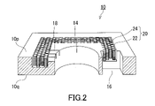
- FIG. 2 is a cross-sectional perspective view of the cell body along the line II-II of FIG.
- FIG. 3A is a partially enlarged view of the gas generating section.
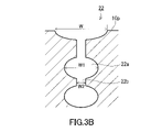
- FIG. 3B is a partially enlarged view showing another example of the groove structure.
- FIG. 4A is a process diagram showing a method for manufacturing a metal gas filled cell.
- FIG. 4B is a process diagram following FIG. 4A.
- FIG. 4C is a process diagram showing a method for manufacturing a metal gas-filled cell according to a modified example.
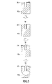
- FIG. 5 is a diagram showing a process sequence when forming a gas generating portion by deep-drilling reactive ion etching.
- FIG. 6A is a diagram schematically showing the action of the gas generating section when the raw material solution is introduced into the gas generating section and the cell body is heated.
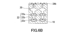
- FIG. 6B is a diagram schematically showing the action of the gas generating portion when precipitating a solid raw material using a cell body that is not closed by the first glass plate.
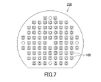
- FIG. 7 is a plan view of an aggregate including a plurality of metal gas filled cells.
- FIG. 8 is a plan view of the metal gas-filled cell according to the first modification.
- FIG. 9 is a plan view of the metal gas filled cell according to the modified example 2.
- FIG. 10 is a plan view of the metal gas filled cell according to the modified example 3.
- FIG. 11A is a plan view (top view) of the metal gas-filled cell according to the modified example 4.
- FIG. 11B is a bottom view of the metal gas filled cell according to the modified example 4.
- FIG. 11C is a cross-sectional view of the metal gas filled cell according to the modified example 4.
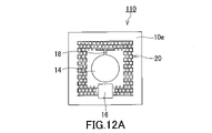
- FIG. 12A is a plan view (top view) of the metal gas-filled cell according to the modified example 5.
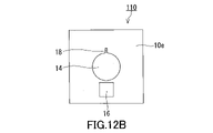
- FIG. 12B is a bottom view of the metal gas filled cell according to the modified example 5.
- FIG. 12C is a cross-sectional view of the metal gas filled cell according to the modified example 5.
- FIG. 13A is a plan view (top view) of the metal gas-filled cell according to the modified example 6.
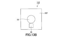
- FIG. 13B is a bottom view of the metal gas filled cell according to the modified example 6.
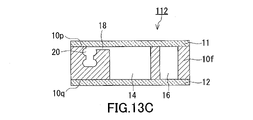
- FIG. 13C is a cross-sectional view of the metal gas filled cell according to the modified example 6.
- FIG. 14 is a plan view of the metal gas filled cell according to the modified example 7.
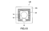
- FIG. 15 is a plan view of the metal gas filled cell according to the modified example 8.
- FIG. 16 is a plan view of the metal gas filled cell according to the modified example 9.
- FIG. 17 is a plan view of the metal gas filled cell according to the modified example 10.
- FIG. 18 is a cross-sectional view of the metal gas filled cell according to the modified example 11.
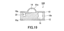
- FIG. 19 is a cross-sectional view of the metal gas filled cell according to the modified example 12.
- FIG. 20 is a cross-sectional view of the metal gas filled cell according to the modified example 13.
- FIG. 21A is a cross-sectional view taken along the line A-A'of the metal gas-filled cell according to the modified example 14.
- FIG. 21B is a plan view (top view) of the metal gas-filled cell according to the modified example 14.
- FIG. 22A is a cross-sectional view of the cell body according to the modified example 15.
- FIG. 22B is a plan view of the cell body according to the modified example 15.
- FIG. 23 is a cross-sectional view of the metal gas filled cell according to the modified example 16.
- FIG. 24 is a plan view of a microchannel having another structure.
- FIG. 25 is a perspective view of the metal gas-filled cell according to the second embodiment of the present invention.
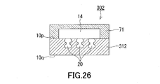
- FIG. 26 is a cross-sectional view of the metal gas filled cell according to the modified example 17.
- FIG. 27 is a graph obtained by normalizing and fitting graphs of absorbance at 60 ° C, 70 ° C and 80 ° C.
- FIG. 28 is a cross-sectional SEM image of the gas generating portion of the metal gas-filled cell of the embodiment.
- FIG. 1 is a perspective view of a metal gas-filled cell 100 according to the first embodiment of the present invention.
- FIG. 2 is a cross-sectional perspective view of the cell body 10 along the line II-II in FIG.
- the metal gas-filled cell 100 has a cell body 10, a first glass plate 11, and a second glass plate 12.
- the cell body 10 has a first surface 10p and a second surface 10q.
- the first surface 10p and the second surface 10q are surfaces facing each other.
- the first surface 10p and the second surface 10q may be the main surfaces of the cell body 10, respectively.
- "Main surface” means the surface having the largest area.
- the first glass plate 11 is attached to the first surface 10p.
- the second glass plate 12 is attached to the second surface 10q.
- the first glass plate 11 and the second glass plate 12 cover the entire surface of the first surface 10p and the entire surface of the second surface 10q, respectively.
- the first surface 10p may include a portion not covered by the first glass plate 11.
- the second surface 10q may include a portion not covered by the second glass plate 12.
- a metal gas and a buffer gas are sealed inside the metal gas-filled cell 100.
- the metal gas typically contains an alkali metal gas such as K, Rb, Cs.
- the metal gas filled cell 100 can function as an atomic oscillator by detecting CPT resonance.
- the buffer gas include an inert gas.
- the inert gas include H 2 gas, N 2 gas, noble gas, and a mixed gas thereof.
- the buffer gas is not essential, and only the metal gas may be enclosed.
- Each of the first glass plate 11 and the second glass plate 12 is a thin glass plate that sufficiently transmits light in a predetermined wavelength band.
- Light in a predetermined wavelength band means light emitted when the metal gas-filled cell 100 is actually used.
- the metal gas is a Cs gas
- the light in a predetermined wavelength band is the light in the absorption wavelength band of Cs (Cs-D1 line, 894.6 nm).
- “Sufficiently transmitted” means, for example, that the transmittance of light in a predetermined wavelength band is 90% or more.
- Glass plates that can be anode-bonded to the cell body 10 can be used as the first glass plate 11 and the second glass plate 12. Examples of the glass that can be anode-bonded to silicon include silicate glass, borosilicate glass, aluminosilicate glass, and aluminoborosilicate glass.
- the cell body 10 is made of, for example, silicon.
- a plurality of metal gas filled cells 100 can be manufactured from one silicon wafer. Since silicon does not easily react with alkali metal gas and buffer gas, when the cell body 10 is made of silicon, the internal atmosphere of the metal gas-filled cell 100 can be kept stable and the vapor pressure of the alkali metal gas is constant. Can be kept in. By using a high quality silicon wafer, it can be expected that the performance of the metal gas filled cell 100 will be improved. Further, when the cell body 10 is made of silicon, the first glass plate 11 and the second glass plate 12 can be bonded to the cell body 10 by anode bonding without using other bonding materials.
- the material of the cell body 10 is not particularly limited.
- the cell body 10 may be made of a metal such as stainless steel or glass as long as it is a material capable of microfabrication.
- the shape of the cell body 10 is also not particularly limited.
- the cell body 10 may have a plate-like shape in a plan view, a cylindrical shape, or a rectangular parallelepiped shape.
- the fact that the cell body 10 has a rectangular parallelepiped shape means that the polyhedron having the smallest volume surrounding the cell body 10 is a rectangular parallelepiped.
- the method of joining the first glass plate 11 and the second glass plate 12 to the cell body 10 is also not particularly limited.
- At least one of the first glass plate 11 and the second glass plate 12 may be attached to the cell body 10 by using a joining material such as an adhesive, a glass frit, or a metal material.
- the method of joining the cell body 10 and the first glass plate 11 may be different from the method of joining the cell body 10 and the second glass plate 12.
- the cell body 10 has an optical chamber 14, a dropping port 16, and a gas generating unit 20.
- the optical chamber 14 may be provided on the first glass plate 11 and / or the second glass plate 12.
- the optical chamber 14 may be a portion that is provided in at least one selected from the cell body 10, the first glass plate 11, and the second glass plate 12 and communicates with the gas generation unit 20.
- the optical chamber 14 is a portion in which a metal gas is sealed, and is a light passage for detecting CPT resonance.
- the optical chamber 14 is open to at least one of the first surface 10p and the second surface 10q.
- the optical chamber 14 is a through hole extending from the first surface 10p to the second surface 10q of the cell body 10.
- the cross-sectional area of the through hole may be constant or variable with respect to the thickness direction of the cell body 10.
- the through hole as the optical chamber 14 is located in the center of the cell body 10. However, as will be described later, it is also possible to use a bottomed hole opened only in the first surface 10p or the second surface 10q as an optical chamber.
- the shape of the optical chamber 14 is not particularly limited.
- the shape of the optical chamber 14 may be circular in plan view, elliptical, or polygonal.
- the position of the optical chamber 14 is not particularly limited, and the optical chamber may be provided at a position deviated from the center of the cell body 10.
- the drip port 16 is a part for receiving a raw material solution of metal gas.
- the dropping port 16 is a through hole extending from the first surface 10p to the second surface 10q.
- the drip port 16 is separated from the optical chamber 14.
- the dropping port 16 communicates directly with the gas generating unit 20 or indirectly via another channel.
- the shape of the dropping port 16 is not particularly limited.
- the shape of the dropping port 16 in a plan view may be polygonal, circular, or elliptical as shown in the figure.
- the opening area of the dropping port 16 is smaller than the opening area of the optical chamber 14.
- Such a structure contributes to the miniaturization of the metal gas filled cell 100.
- the sizes of the optical chamber 14 and the dropping port 16 are not particularly limited.
- the gas generation unit 20 is a part for generating a solid raw material of metal gas from a raw material solution of metal gas and also generating metal gas from the solid raw material.
- the gas generating unit 20 may form at least a part of the path from the dropping port 16 to the optical chamber 14.
- the gas generation unit 20 has a plurality of grooves 22 opened on the first surface 10p.
- the plurality of grooves 22 are bottomed grooves.
- the gas generating unit 20 has the shape of a frame surrounding the optical chamber 14 in a plan view. One end and the other end of the gas generation unit 20 face the dropping port 16. In other words, the dropping port 16 is provided so as to penetrate a part of the gas generating portion 20 in the shape of a frame.
- the gas generation unit 20 has a plurality of pillars 24 in addition to the plurality of grooves 22.
- the plurality of grooves 22 extend in a grid pattern in a plan view so that the gas generating unit 20 has the plurality of pillars 24.
- a plurality of grooves 22 are formed so that the plurality of pillars 24 are arranged in a staggered pattern. With such a fine structure, it is possible to sufficiently secure the surface area on which the solid raw material of the metal gas should be deposited.
- the pillar 24 has a rectangular shape (typically a square) in a plan view. However, the shape of the pillar 24 is not particularly limited.
- the shape of the pillar 24 may be a prismatic shape or a cylindrical shape.
- FIG. 3A is a partially enlarged view of the gas generation unit 20.
- the width of each of the plurality of grooves 22 changes periodically along the thickness direction DR of the cell body 10.
- the thickness direction DR of the cell body 10 is the direction from the first surface 10p to the second surface 10q.
- Each of the plurality of grooves 22 has a portion wider than the opening width W of each of the plurality of grooves 22 on the first surface 10p.
- each of the plurality of grooves 22 includes a plurality of first portions 22a and a plurality of second portions 22b.
- the first portion 22a is a portion where the distance between the adjacent pillars 24 and the pillars 24 is long.
- the second portion 22b is a portion where the distance between the adjacent pillars 24 and the pillars 24 is short.
- the first portion 22a and the second portion 22b are alternately provided from the first surface 10p toward the second surface 10q.
- the width W2 of the second portion 22b of the groove 22 is, for example, equal to the opening width W of the groove 22 on the first surface 10p.
- the first portion 22a of the seven stages is provided along the thickness direction DR.
- the number of the first portion 22a and the second portion 22b is not particularly limited.
- the solid raw material When a solid raw material is produced from a metal gas raw material solution, the solid raw material tends to adhere to the fine structure constituting the gas generating unit 20 and stay in the gas generating unit 20. Further, the fine structure of the gas generating unit 20 makes the chemical reaction by heating a solid raw material such as CsN 3 more efficient. Due to the combined effect of increasing the specific surface area and preventing the solid raw material from scattering during thermal decomposition, alkali metal gas can be efficiently generated by the chemical reaction of the solid raw material even at a low temperature.
- the width W of the groove 22 on the first surface 10p is, for example, 1 ⁇ m or more and 100 ⁇ m or less.
- the width W1 of the first portion 22a of the groove 22 is, for example, 5 ⁇ m or more and 200 ⁇ m or less.
- the width W2 of the second portion 22b of the groove 22 is substantially equal to the width W of the groove 22 on the first surface 10p.
- the width W1 of the first portion 22a and the width W2 of the second portion 22b may be gradually narrowed from the first surface 10p to the second surface 10q.
- the length of one side L of the pillar 24 on the first surface 10p is, for example, 50 ⁇ m or more and 500 ⁇ m or less.
- FIG. 3B is a partially enlarged view showing another example of the structure of the groove 22.
- the opening of the groove 22 on the first surface 10p is expanded in advance by etching, and then reactive ion etching described later is performed so that the first portion 22a and the second portion 22b are formed. It is also good.
- the opening width W of the groove 22 on the first surface 10p is wider than the width W1 of the first portion 22a and wider than the width W2 of the second portion 22b. According to such a structure, even if a solid raw material such as CsN 3 is deposited in the opening of the groove 22, it does not easily interfere with the joining between the cell body 10 and the first glass plate 11.
- a microchannel 18 for communicating the optical chamber 14 and the gas generating unit 20 is provided.
- each of the plurality of grooves opened in the first surface 10p plays the role of the microchannel 18.
- the width of the groove as the microchannel 18 is narrower than, for example, the width W of the groove 22 in the gas generating unit 20.
- the width of the groove as the microchannel 18 is, for example, 1 ⁇ m or more and 30 ⁇ m or less.
- the position of the microchannel 18 is not particularly limited.
- the microchannel 18 is provided on the 180-degree opposite side of the dropping port 16 with the optical chamber 14 as the center. Therefore, it is difficult for the solid or liquid raw material of the metal gas to be introduced by the optical chamber 14.
- the microchannel 18 may be composed of only one groove.
- FIG. 4A and 4B are process diagrams showing a method for manufacturing the metal gas filled cell 100.
- FIG. 4A shows a method of manufacturing the cell body 10.
- FIG. 4B shows a method of manufacturing a metal gas-filled cell 100 using the cell body 10.
- a thin film 30 for mask is formed on one surface of the substrate 10y.
- the thin film 30 may be a metal thin film such as Cr, Al, or Ni, or may be a silicon oxide film.
- the thin film 30 can be formed by a vapor phase method such as thin film deposition or sputtering.
- the substrate 10y is, for example, a silicon wafer. Since a plurality of metal gas-filled cells 100 can be manufactured from one substrate 10y, the method of this embodiment is excellent in productivity.
- the silicon wafer as the substrate 10y may be a polycrystalline wafer or a single crystal wafer.
- the internal atmosphere of the metal gas filled cell 100 can be kept more stable, and the vapor pressure of the alkali metal gas can be kept more constant. Since the single crystal wafer has no grain boundaries, it is easy to form the fine structure of the gas generating portion 20 with high dimensional accuracy. The larger the substrate 10y, the more compact the metal gas-filled cell 100 can be mass-produced.
- the resist 32 is applied to the surface of the thin film 30, and the resist 32 is patterned using a photolithography technique.
- the thin film 30 may be omitted and the resist 32 may be formed directly on the substrate 10y.
- step 3 a part of the thin film 30 is removed with an etching solution to expose the surface of the substrate 10y.
- the optical chamber 14, the dropping port 16 and the gas generating unit 20 are formed by deep reactive ion etching (Deep Reactive Ion Etching).
- the optical chamber 14, the dropping port 16 and the gas generating unit 20 are collectively formed by deep reactive ion etching. Therefore, it is possible to manufacture the cell body 10 with a small number of steps.
- the optical chamber 14 is provided on the first glass plate 11 and / or the second glass plate 12, the dropping port 16 and the gas generating portion 20 are formed by step 4.
- the microchannel 18 is also formed by step4.
- the dropping port 16 and the gas generating unit 20 are collectively formed, unevenness is imparted not only to the gas generating unit 20 but also to the inner peripheral surface of the optical chamber 14 and the inner peripheral surface of the dropping port 16.
- the gas generation unit 20 is formed by deep reactive ion etching from one surface (first surface) of the substrate 10y.
- the optical chamber 14 and the dropping port 16 are formed by deep reactive ion etching from the other surface (second surface) of the substrate 10y.
- FIG. 5 is a diagram showing a process sequence when the gas generation unit 20 is formed by deep-drilling reactive ion etching.
- etching with sulfur hexafluoride (SF 6 ) and formation of a protective film using carbon fluorofluoride (C 4 F 8 ) are repeated a plurality of times to form a groove.
- fluorocarbon is used to form a thick protective film 36 on the inner peripheral surface of the groove.
- the protective film 36 on the bottom surface of the groove is removed using sulfur hexafluoride, and isotropic etching is performed.
- Alternative gases such as CHF 3 and CFI 3 may be used in place of fluorocarbon.
- the cell body 10 is obtained by removing the thin film 30 and the resist 32.
- the first glass plate 11 is attached to the first surface 10p of the cell body 10, and the plurality of grooves 22 and the dropping port 16 of the gas generating unit 20 are covered.
- the optical chamber 14 is also open to the first surface 10p, the optical chamber 14, the gas generating unit 20, and the dropping port 16 are covered by the first glass plate 11.
- the method of joining the first glass plate 11 and the cell body 10 is an anode joining. In the anode bonding, the first glass plate 11 and the cell body 10 are overlapped with each other, and a DC voltage is applied between the two while heating the two.
- the heating temperature is, for example, 150 ° C. or higher and 600 ° C. or lower.
- the applied voltage is, for example, 200 V or more and 1200 V or less.
- the dimensions of the first glass plate 11 in a plan view may match the dimensions of the first surface 10p of the cell body 10.
- the metal gas raw material solution 34a is injected into the dropping port 16 in a state where the first glass plate 11 is located below the gas generating section 20 in the vertical direction, and the raw material solution 34a is gas. It is introduced into the generation unit 20.
- the raw material solution 34a is injected into the dropping port 16 from the side of the second surface 10q. Since the first glass plate 11 serves as the bottom of the gas generating section 20, the raw material solution 34a does not overflow from the groove 22.
- the raw material solution 34a is a solution containing a metal compound.
- the metal compound include metal azides such as CsN 3 and metal halides such as CsCl.
- the metal compound is typically an alkali metal compound.
- an alkali metal gas is generated by using a chemical reaction of an alkali metal compound.
- a CsN 3 solution is introduced into the gas generating section 20 of the cell body 10 to precipitate solid CsN 3 .
- the solvent in the CsN 3 solution may be an inorganic solvent such as water or an organic solvent such as alcohol, acetone or acetonitrile.
- Cs and N 2 are produced according to the following chemical reaction.
- the alkali metal production method by thermal decomposition of the metal azide is an alkali metal gas and an N 2 gas which is a buffer gas without producing a product which affects the performance such as the gas pressure inside the metal gas filled cell 100.
- N 2 gas which is a buffer gas without producing a product which affects the performance such as the gas pressure inside the metal gas filled cell 100.
- the alkali metal compound is not limited to the metal azide.
- Cs gas can be generated by reacting CsCl with BaN 6 .
- the alkali metal production method by thermal decomposition of the metal azide has the advantage that it does not generate by-products other than the alkali metal and N 2 , and the by-products do not affect the gas pressure.
- step 8 the solvent contained in the raw material solution 34a is evaporated, and the solid raw material 34b of the metal gas is deposited in the gas generation unit 20. Specifically, the solvent is evaporated by heating the cell body 10. Heating of the cell body 10 can be achieved by arranging the cell body 10 on a hot plate or treating the cell body 10 in a heating furnace.
- FIG. 6A is a diagram schematically showing the action of the gas generating unit 20 when the raw material solution 34a is introduced into the gas generating unit 20 and the cell body 10 is heated.
- the arrows in the figure indicate the flow of steam generated from the raw material solution 34a and the raw material solution 34a.
- the raw material solution 34a does not overflow to the outside of the gas generating section 20. .. Since the solid raw material 34b can be generated from almost the entire amount of the injected raw material solution 34a, a sufficient amount of the solid raw material 34b can be deposited in the gas generation unit 20.
- the heating temperature of the cell body 10 when depositing the solid raw material 34b on the gas generating unit 20 is, for example, 25 ° C. or higher and 315 ° C. or lower. According to the present embodiment, even if the cell body 10 is heated at a relatively high temperature and the raw material solution 34a boils, the possibility that the raw material solution 34a overflows from the gas generating unit 20 is low.
- the "heating temperature” is the ambient temperature at which the cell body 10 is placed. When using a hot plate, the heating temperature is the surface temperature of the hot plate. When using a heating furnace, the heating temperature is the temperature inside the heating furnace.
- FIG. 6B is a diagram schematically showing the action of the gas generating unit 20 when the solid raw material 34b is deposited using the cell body 10 which is not closed by the first glass plate 11.
- the raw material solution 34a may overflow from the groove 22. Therefore, it is necessary to inject an excessive amount of the raw material solution 34a into the gas generation unit 20 in advance. Further, it is necessary to directly inject the raw material solution 34a into the gas generation unit 20 using a device such as a micropipette. This process is very complicated. Further, the solid raw material 34b of the metal gas adheres to the surface of the cell body 10.
- the solid raw material 34b interferes with the anode bonding between the first glass plate 11 and the cell body 10, the solid raw material 34b overflowing from the gas generating unit 20 must be removed. Of course, the amount of the solid raw material 34b deposited on the gas generation unit 20 is insufficient. According to the method of the present embodiment, such a disadvantage can be avoided.
- the second glass plate 12 is attached to the second surface 10q of the cell body 10.
- the dimensions of the second glass plate 12 in a plan view may match the dimensions of the second surface 10q of the cell body 10.
- the method of joining the second glass plate 12 and the cell body 10 is also an anode joining. In the anode bonding, the second glass plate 12 and the cell body 10 are overlapped with each other, and a DC voltage is applied between the two while heating the two.
- the heating temperature is, for example, 150 ° C. or higher and 300 ° C. or lower.
- the applied voltage is, for example, 200 V or more and 1200 V or less.
- the step 9 step is performed in vacuum or in an atmosphere of an inert gas such as a rare gas or N 2 gas.
- the degree of vacuum is, for example, 1 ⁇ 10 -3 Pa or more and 1 ⁇ 10 -7 Pa or less.
- a metal gas is generated from the solid raw material 34b, and the metal gas is introduced into the optical chamber 14.
- the cell body 10 is heated to generate a metal gas from the solid raw material 34b.
- Heating of the cell body 10 can be achieved by arranging the cell body 10 on a hot plate or treating the cell body 10 in a heating furnace.
- the heating temperature of the cell body 10 when generating the metal gas is, for example, 250 ° C. or higher and 400 ° C. or lower.
- the solid raw material 34b is decomposed by UV irradiation to generate a metal gas, or the solid raw material 34b is decomposed by laser light irradiation to generate a metal gas. May be good.
- the bonding of the second glass plate 12 to the second surface 10q of the cell body 10 is the heating temperature when the cell body 10 is heated to generate the metal gas. It is desirable to carry out less than. Specifically, it is desirable that the second glass plate 12 is bonded to the second surface 10q of the cell body 10 at a temperature lower than the decomposition temperature of the solid raw material 34b. If the temperature of the cell body 10 is kept below the decomposition temperature of the solid raw material 34b when the second glass plate 12 is attached to the second surface 10q, it is possible to prevent gas from being generated from the solid raw material 34b, and the metal gas filled cell 100 It is possible to prevent the pressure inside the body from rising.
- the metal gas-filled cell 100 of the present embodiment is obtained.
- a part of the solid raw material 34b remains in the gas generation unit 20 without being decomposed. That is, the metal gas-filled cell 100 has a solid raw material 34b of metal gas adhering to the gas generation unit 20.
- no member or material other than the solid raw material 34b is present inside the metal gas filled cell 100. Therefore, the internal atmosphere of the metal gas-filled cell 100 can be kept stable, and the vapor pressure of the alkali metal gas can be kept constant. Since the solid raw material 34b remains in the gas generation unit 20, when the vapor pressure of the metal gas in the optical chamber 14 decreases due to deterioration over time, the metal gas is compensated by reheating the metal gas filled cell 100. Is also possible.
- the step 10 step may be performed immediately before using the metal gas filled cell 100. That is, it is conceivable that the manufacturer carries out the steps up to step 9, and the user carries out only the steps up to step 10.
- FIG. 4C is a process diagram showing a method of manufacturing the metal gas filled cell 100 according to the modified example.
- the steps up to step 8 in this modification are as described with reference to FIGS. 4A and 4B.
- the solid raw material 34b is deposited in the gas generation unit 20, and then the metal gas is generated from the solid raw material 34b.
- the cell body 10 is heated to generate a metal gas from the solid raw material 34b.
- the second glass is above the second surface 10q of the cell body 10 so that the generated metal gas comes into contact with the surface of the second glass plate 12 and the metal thin film 37 is deposited on the surface of the second glass plate 12.
- the plate 12 is arranged.
- step9a represent the flow of the generated metal gas.
- the step9a step is performed in vacuum or in an atmosphere of an inert gas such as a rare gas or N 2 gas.
- the degree of vacuum is, for example, 1 ⁇ 10 -3 Pa or more and 1 ⁇ 10 -7 Pa or less.
- step 10a the cell body 10 and the second glass plate 12 are arranged under the atmosphere of an inert gas 38 such as N 2 gas.
- step 11a the second glass plate 12 is attached to the second surface 10q of the cell body 10. This step is as described with reference to step 9 in FIG. 4B.
- step12a the cell body 10 is heated to the driving temperature of the metal gas-filled cell 100.
- the metal gas 39 is supplied to the optical chamber 14 from the metal thin film 37 on the surface of the second glass plate 12.
- FIG. 7 is a plan view of an aggregate 200 including a plurality of metal gas filled cells 100.
- a plurality of metal gas-filled cells 100 can be obtained from one silicon wafer. By cutting the aggregate 200 along a predetermined cutting line, it can be separated into individual metal gas filled cells 100.
- the aggregate 200 shown in FIG. 7 includes a metal gas-filled cell having a design different from that of the metal gas-filled cell 100 described with reference to FIG. 1. That is, it is also possible to create a plurality of metal gas-filled cells having different designs on one silicon wafer by using the MEMS processing technique.
- the assembly 200 may include only the metal gas filled cell 100 of a single design.
- the step of cutting the aggregate 200 may be performed before the step of step 10 for generating the metal gas (FIG. 4B), or may be performed after the step of step 10. According to the method of the present embodiment, the selection is possible.
- FIG. 8 is a plan view of the metal gas filled cell 102 according to the first modification.
- the cell body 10a has three sets of microchannels 18 including a plurality of grooves.
- the gas generating unit 20 has the shape of a rectangular frame in a plan view.
- a dropping port 16 is provided on one side of a rectangular frame.
- Microchannels 18 are provided at three locations around the optical chamber 14 so as to communicate each of the other three sides with the optical chamber 14.
- FIG. 9 is a plan view of the metal gas filled cell 104 according to the modified example 2.
- the cell body 10b has two sets of microchannels 18 and a plurality (two) dropping ports 16.
- Each drip port 16 is arranged around the optical chamber 14 at equal angular intervals.
- each dropping port 16 is provided at a position of 0 degrees and a position of 180 degrees with respect to the optical chamber 14 in a plan view.
- Microchannels 18 are provided at 90 degree positions and 270 degree positions, respectively. According to such a structure, the injection amount of the CsN 3 aqueous solution in each dropping port 16 can be reduced, so that the CsN 3 aqueous solution is less likely to leak from the dropping port 16 during heating.
- FIG. 10 is a plan view of the metal gas filled cell 106 according to the modified example 3.
- the gas generation unit 20a of the cell body 10c includes the first region 40 and the second region 41.
- the arrangement pattern of the plurality of pillars 24 in the first region 40 is different from the arrangement pattern of the plurality of pillars 24 in the second region 41.
- the plurality of pillars 24 are arranged so as to form a square lattice.
- the plurality of pillars 24 are arranged in a staggered manner.
- the first region 40 and the second region 41 are arranged in this order.
- FIG. 11A is a plan view (top view) of the metal gas filled cell 108 according to the modified example 4.
- FIG. 11B is a bottom view of the metal gas filled cell 108 according to the modified example 4.
- FIG. 11C is a cross-sectional view of the metal gas filled cell 108 according to the modified example 4.
- the cell body 10d has a microchannel 18 opened on the second surface 10q.
- the gas generation unit 20 is open to the first surface 10p.
- the bottom of the microchannel 18 and the bottom of the gas generating section 20 communicate with each other inside the cell body 10d. In other words, the sum of the depth of the microchannel 18 and the depth of the gas generating unit 20 exceeds the thickness of the cell body 10d.
- the gas generation unit 20 and the optical chamber 14 communicate with each other through the microchannel 18.
- the gas generation unit 20 is formed by deep reactive ion etching from the 10p side of the first surface.
- the optical chamber 14, the dropping port 16 and the microchannel 18 are formed by deep reactive ion etching from the second surface 10q side. As a result, the cell body 10d is obtained.
- FIG. 12A is a plan view (top view) of the metal gas filled cell 110 according to the modified example 5.
- FIG. 12B is a bottom view of the metal gas filled cell 110 according to the modified example 5.
- FIG. 12C is a cross-sectional view of the metal gas filled cell 110 according to the modified example 5.
- the cell body 10e has microchannels 18 opened on both sides of the first surface 10p and the second surface 10q. That is, in this modification, the microchannel 18 is a through hole.
- the dropping port 16 and the microchannel 18 are through holes, the cell body 10e can be easily manufactured.
- FIG. 13A is a plan view (top view) of the metal gas filled cell 112 according to the modified example 6.
- FIG. 13B is a bottom view of the metal gas filled cell 112 according to the modified example 6.
- FIG. 13C is a cross-sectional view of the metal gas filled cell 112 according to the modified example 6.
- the cell body 10f has a microchannel 18 opened on the first surface 10p.
- the depth of the microchannel 18 is, for example, 10 ⁇ m or less.
- the microchannel 18 has a width sufficiently wider than the depth. In this modification, the microchannel 18 is a wide, shallow groove.
- the arrangement and shape of the microchannel 18 are not particularly limited. Further, the microchannel may be provided on the first glass plate 11, or the microchannel may be provided on both the cell body and the first glass plate 11.
- FIG. 14 is a plan view of the metal gas filled cell 114 according to the modified example 7.
- the cell body 10g has a joint portion 44 located between the dropping port 16 and the gas generating portion 20 to communicate the two.
- the joint portion 44 includes, for example, a groove opened in the first surface 10p.
- the dropping port 16 and the gas generating portion 20 may indirectly communicate with each other via the joining portion 44.
- FIG. 15 is a plan view of the metal gas filled cell 116 according to the modified example 8.
- the microchannel 18 of the cell body 10h communicates the optical chamber 14 with the gas generating unit 20 via the dropping port 16.
- the metal gas and the buffer gas are sent to the optical chamber 14 while preventing the raw material solution 34a from directly entering the optical chamber 14 from the dropping port 16. It is possible.
- FIG. 16 is a plan view of the metal gas filled cell 118 according to the modified example 9.
- the cell body 10i has an additional chamber 48 located between the microchannel 18 and the gas generator 20.
- the additional chamber 48 is, for example, a through hole and serves to prevent liquid or solid CsN 3 leaking from the gas generator 20 from entering the optical chamber 14 via the microchannel 18.
- the dropping port 16 and the gas generating portion 20 communicate with each other via the joint portion 44.
- the optical chamber 14 does not have to be surrounded by the gas generating unit 20.
- FIG. 17 is a plan view of the metal gas filled cell 120 according to the modified example 10.
- the cell body 10j has an optical chamber 141 configured with a bottomed hole.
- An inclined portion 141p for reflecting light is provided at the bottom of the bottomed hole as the optical chamber 141.
- the surface of the inclined portion 141p is a mirror surface.
- a metal film for increasing the reflectance of light may be provided on the surface of the inclined portion 141p. The light passes through the first glass plate 11 and travels to the optical chamber 141, repeats reflection at the inclined portion 141p, passes through the first glass plate 11 again, and travels to the outside of the metal gas filled cell 120.
- FIG. 18 is a cross-sectional view of the metal gas filled cell 122 according to the modified example 11.
- the metal gas-filled cell 122 includes a cell body 10k, a first glass plate 51, and a second glass plate 12.
- the first glass plate 51 has an optical chamber 14.
- a metal gas is sealed in the optical chamber 14.
- the optical chamber 14 of the first glass plate 51 communicates with the gas generation unit 20 via the microchannel 18.
- the depth of the optical chamber 14 is adjusted so that the laser beam emitted in the in-plane direction perpendicular to the thickness direction of the metal gas filled cell 122 can pass through the optical chamber 14.
- the first glass plate 51 may be a glass cube having a shape such as a rectangular parallelepiped or a cylinder.
- the thickness direction of the metal gas filled cell 122 is defined as the Z direction
- the plane parallel to the first plane 10p and the second plane 10q is the XY plane.
- FIG. 19 is a cross-sectional view of the metal gas filled cell 124 according to the modified example 12.
- the metal gas filled cell 124 also includes a first glass plate 61 having an optical chamber 14.
- the first glass plate 61 has a dome-shaped convex portion 61a.
- the dome-shaped convex portion 61a secures a space that functions as the optical chamber 14.
- the "glass plate” in the present specification is not necessarily limited to a glass plate thinner than the cell body. Also, the glass plate may have protrusions or recesses for the optical chamber.
- FIG. 20 is a cross-sectional view of the metal gas filled cell 126 according to the modified example 13.
- the metal gas-filled cell 126 includes a cell body 10 m, a first glass plate 11 and a second glass plate 52.
- the second glass plate 52 has an optical chamber 14.
- the position of the optical chamber 14 is not particularly limited.
- the optical chamber 14 may be provided in at least one selected from the cell body, the first glass plate, and the second glass plate.
- a part of the optical chamber 14 may be provided on the first glass plate, and the rest of the optical chamber 14 may be provided on the cell body.
- the optical chamber 14 is provided in the cell body 10 (FIG. 1), the metal gas-filled cell 100 can be easily thinned. The trouble of processing the glass plate can be omitted.
- FIG. 21A is a cross-sectional view of the metal gas filled cell 128 according to the modified example 14 along the A-A'line.
- FIG. 21B is a plan view (top view) of the metal gas filled cell 128 according to the modified example 14.
- the metal gas-filled cell 128 includes a cell body 10n, a first glass plate 11, and a second glass plate 62.
- the second glass plate 62 has an optical chamber 14.
- the optical chamber 14 and the dropping port 16 overlap each other in the in-plane direction parallel to the first surface 10p and the second surface 10q. In this modification, the optical chamber 14 and the dropping port 16 overlap each other on the second surface 10q.
- the dropping port 16 is housed inside the optical chamber 14.
- the cell body 10n is not provided with a microchannel.
- the dropping port 16 also serves as a path from the gas generating unit 20 to the optical chamber 14. With such a structure, microchannels can be omitted.
- the method for manufacturing the metal gas-filled cell 128 is as described with reference to FIGS. 4A and 4B. That is, the first glass plate 11 is attached to the first surface 10p of the cell body 10n, the raw material solution 34a of the metal gas is injected into the dropping port 16, and the raw material solution 34a is introduced into the gas generation unit 20. The solvent contained in the raw material solution 34a is evaporated, and the solid raw material 34b of the metal gas is deposited in the gas generation unit 20. The second glass plate 62 is attached to the second surface 10q of the cell body 10n. A metal gas is generated from the solid raw material 34b, and the metal gas is introduced into the optical chamber 14.
- FIG. 22A is a cross-sectional view of the cell body 10s according to the modified example 15.
- FIG. 22B is a plan view of the cell body 10s according to the modified example 15.
- the cell body 10s is not provided with the dropping port 16 (FIG. 1), and the optical chamber 14 also serves as the dropping port. That is, it is also possible to introduce the metal gas raw material solution 34a into the gas generation unit 20 through the optical chamber 14. Since the drip port is omitted, the cell body 10s has a simple structure.
- the arrow in FIG. 22A indicates the flow of the raw material solution 34a.
- FIG. 23 is a cross-sectional view of the metal gas filled cell 130 according to the modified example 16.
- the metal gas-filled cell 130 includes a cell body 10t, a first glass plate 71, and a second glass plate 12.
- the microchannel 18 is provided on the first glass plate 71.
- the microchannel 18 may be provided on both the cell body 10t and the first glass plate 71.
- FIG. 24 is a plan view of the microchannel 81 having another structure.
- the width of the microchannel 81 is not constant.
- the microchannel 81 has a first portion 18a and a second portion 18b.
- the width of the first portion 18a is narrower than the width of the second portion 18b. According to such a structure, it is easy to prevent the raw material solution 34a of the metal gas from entering the optical chamber 14.
- the microchannel 81 may have a plurality of first portions 18a and a plurality of second portions 18b.
- the depth of the microchannel is arbitrary. That is, the microchannel may have a plurality of portions having different depths from each other. For example, in the microchannel 81 shown in FIG. 24, the depth of the first portion 18a may be different from the depth of the second portion 18b.
- FIG. 25 is a perspective view of the metal gas filled cell 300 according to the second embodiment of the present invention.
- the metal gas-filled cell 300 has a cell body 310 and a glass plate 11.
- the cell body 310 has a first surface 10p and a second surface 10q.
- a glass plate 11 is attached to the first surface 10p.
- the cell body 310 has an optical chamber 141, a drip port 316, and a gas generating unit 20.
- the cell body 310 does not have a through hole.
- the glass plate 11 is attached only to the first surface 10p.
- Both the optical chamber 141 and the dropping port 316 are bottomed holes that are open only on the first surface 10p.
- the structure of the optical chamber 141 is as described with reference to FIG.
- the drip port 316 communicates with the gas generation unit 20. It is possible to supply the raw material solution 34a to the gas generating unit 20 through the dropping port 316. In the present embodiment, it can be said that a part of the gas generating unit 20 also serves as the dropping port 316.
- the metal gas filled cell 300 can be manufactured by, for example, the following method.
- the cell body 310 is manufactured.
- the method for producing the cell body 310 is the same as the method for producing the cell body 10 described above, except that there is no through hole.
- the raw material solution 34a of the metal gas is injected into the dropping port 316, and the raw material solution 34a is introduced into the gas generation unit 20.
- the raw material solution 34a may be directly introduced into the gas generation unit 20 using a device such as a micropipette.
- the solvent contained in the raw material solution 34a is evaporated, and the solid raw material 34b of the metal gas is deposited in the gas generation unit 20.
- the glass plate 11 is attached to the first surface 10p of the cell body 310 by anode bonding. The glass plates 11 are bonded together in a vacuum or in an atmosphere of an inert gas.
- a metal gas is generated from the solid raw material 34b, and the metal gas is introduced into the optical chamber 141.
- FIG. 26 is a cross-sectional view of the metal gas filled cell 302 according to the modified example 17.
- the metal gas-filled cell 302 includes a cell body 312 and a glass plate 71.
- the cell body 312 has a gas generating unit 20.
- An optical chamber 14 is provided on the glass plate 71.
- the optical chamber 14 and the gas generation unit 20 overlap each other in the in-plane direction parallel to the first surface 10p, which is the joint surface between the cell body 312 and the glass plate 71.
- the optical chamber 14 and the gas generating unit 20 overlap each other on the first surface 10p.
- the cell body 312 is not provided with a microchannel and a drip port. According to this modification, the microchannel and the dropping port can be omitted. Further, the second glass plate can also be omitted.
- the optical chamber 14 and the gas generating unit 20 may directly communicate with each other without passing through the microchannel 18.
- the microchannel 18 is not essential.
- Each of the optical chamber 14, the dropping port 16, the microchannel 18, and the gas generating unit 20 may be formed by through holes. In this case, a part of the groove 22 constituting the gas generating unit 20 is replaced with a through hole.
- a Cr thin film as an etching mask was formed on a silicon single crystal wafer as a substrate.
- a resist (OFPR-800 54cp, manufactured by Tokyo Ohka Kogyo Co., Ltd.) is applied on the Cr thin film by spin coating, and a high-speed maskless exposure device (D-light DL-1000GS / KCH, manufactured by Nano System Solutions Corporation) is applied. The exposure was performed using.
- a developer (SD-1, manufactured by Tokuyama Corporation) was used to form a resist pattern having an opening.
- the Cr thin film was etched with a Cr etching solution (Escreen S-24, manufactured by Sasaki Chemicals Co., Ltd.), and the same pattern as the resist was applied to the Cr thin film. After that, the resist was removed.
- a deep-drilled reactive ion etching apparatus (RIE-800PB-KU, manufactured by SAMCO Corporation) was used to perform deep-drilled etching of the substrate. After the completion of the reactive ion etching, the substrate was washed and the Cr thin film as an etching mask was removed. As a result, a cell body having an optical chamber, a gas generating part, a dropping port and a microchannel was obtained.
- the first glass plate was bonded to the first surface of the cell body by anode bonding.
- As the first glass plate borosilicate glass having a thickness of 0.3 mm was used.
- Anode bonding was carried out under the conditions of 400 ° C. and an applied voltage of 1 kV.
- the posture of the cell body was maintained so that the first glass plate was located on the lower side, and 4.0 ⁇ L of the CsN 3 aqueous solution was injected into the drip port of the cell body to allow it to permeate into the gas generation part.
- the concentration of CsN 3 (manufactured by Sigma-Aldrich) in the CsN 3 aqueous solution was 2.0 mg / ⁇ L.
- the cell body was placed on a hot plate at 80 ° C. to evaporate the water in the CsN 3 aqueous solution.
- a second glass plate was bonded to the second surface of the cell body by anode bonding under a vacuum of 10-5 Pa.
- borosilicate glass having a thickness of 0.3 mm was used as the second glass plate.
- Anode bonding was performed under the conditions of 250 ° C. and an applied voltage of 1 kV.
- the metal gas-filled cell of the example was obtained.
- the shape of the metal gas-filled cell of the example in a plan view was square. Its dimensions were 8 mm x 8 mm x 2.1 mm.
- FIG. 27 is a graph obtained by normalizing and fitting graphs of absorbance at 60 ° C, 70 ° C and 80 ° C. As shown in FIG. 27, the peak became sharper as the temperature increased, and an increase in the Cs vapor pressure inside the metal gas-filled cell was confirmed.
- the entire metal gas-filled cell is heated to about 330 ° C., which is the temperature of thermal decomposition of CsN 3 , and a sufficient amount of Cs gas is generated. Therefore, from room temperature to about 80 ° C., which is the driving temperature of the Cs atomic clock, the vapor pressure of the Cs gas is the saturated vapor pressure. As the temperature of the metal gas-filled cell rises from room temperature to 80 ° C., the saturated vapor pressure rises, so that the vapor pressure of the Cs gas rises and the absorbance also rises.
- FIG. 28 is a cross-sectional SEM image of the gas generating portion of the metal gas-filled cell of the embodiment.
- the solid raw material CsN 3 in the example
- the solid raw material was abundantly present at the bottom of the groove forming the gas generating part.
- the solid material was slightly adhered to the surface of the pillar. That is, the solid raw material is roughly divided into (i) a first residue existing across pillars adjacent to each other so as to fill the bottoms of a plurality of grooves, and (ii) a second residue covering the surface of the pillars. And included.
- the metal gas-filled cell of the present invention is useful for atomic clocks, magnetic sensors, inertial sensors and the like.
Landscapes
- Physics & Mathematics (AREA)
- General Physics & Mathematics (AREA)
- Chemical & Material Sciences (AREA)
- Life Sciences & Earth Sciences (AREA)
- Ecology (AREA)
- Spectroscopy & Molecular Physics (AREA)
- Mechanical Engineering (AREA)
- Analytical Chemistry (AREA)
- Metallurgy (AREA)
- Materials Engineering (AREA)
- Engineering & Computer Science (AREA)
- Chemical Kinetics & Catalysis (AREA)
- Health & Medical Sciences (AREA)
- Organic Chemistry (AREA)
- Biochemistry (AREA)
- General Health & Medical Sciences (AREA)
- Immunology (AREA)
- Pathology (AREA)
- Condensed Matter Physics & Semiconductors (AREA)
- General Chemical & Material Sciences (AREA)
- Optical Measuring Cells (AREA)
Priority Applications (3)
| Application Number | Priority Date | Filing Date | Title |
|---|---|---|---|
| JP2022560741A JP7780803B2 (ja) | 2020-11-06 | 2021-10-27 | 金属ガス封入セル及びその製造方法 |
| US18/251,483 US20230412178A1 (en) | 2020-11-06 | 2021-10-27 | Metal-gas-filled cell and method for manufacturing the same |
| EP21889110.9A EP4243225A4 (en) | 2020-11-06 | 2021-10-27 | METAL GAS SEALED CELL AND ITS MANUFACTURING METHOD |
Applications Claiming Priority (2)
| Application Number | Priority Date | Filing Date | Title |
|---|---|---|---|
| JP2020185571 | 2020-11-06 | ||
| JP2020-185571 | 2020-11-06 |
Publications (1)
| Publication Number | Publication Date |
|---|---|
| WO2022097557A1 true WO2022097557A1 (ja) | 2022-05-12 |
Family
ID=81457859
Family Applications (1)
| Application Number | Title | Priority Date | Filing Date |
|---|---|---|---|
| PCT/JP2021/039690 Ceased WO2022097557A1 (ja) | 2020-11-06 | 2021-10-27 | 金属ガス封入セル及びその製造方法 |
Country Status (4)
| Country | Link |
|---|---|
| US (1) | US20230412178A1 (https=) |
| EP (1) | EP4243225A4 (https=) |
| JP (1) | JP7780803B2 (https=) |
| WO (1) | WO2022097557A1 (https=) |
Cited By (1)
| Publication number | Priority date | Publication date | Assignee | Title |
|---|---|---|---|---|
| WO2024053527A1 (ja) | 2022-09-09 | 2024-03-14 | 国立大学法人京都大学 | 金属ガス封入セル |
Citations (7)
| Publication number | Priority date | Publication date | Assignee | Title |
|---|---|---|---|---|
| JP2013038382A (ja) | 2011-07-13 | 2013-02-21 | Ricoh Co Ltd | 原子発振器及び原子発振器の製造方法 |
| US20150027908A1 (en) * | 2013-07-23 | 2015-01-29 | Texas Instruments Incorporated | Multiple-cavity vapor cell structure for micro-fabricated atomic clocks, magnetometers, and other devices |
| US20150028866A1 (en) * | 2013-07-23 | 2015-01-29 | Texas Instruments Incorporated | Vapor cell structure having cavities connected by channels for micro-fabricated atomic clocks, magnetometers, and other devices |
| JP2015046535A (ja) * | 2013-08-29 | 2015-03-12 | 株式会社リコー | アルカリ金属セルの製造方法及び原子発振器の製造方法 |
| JP2016092465A (ja) * | 2014-10-30 | 2016-05-23 | セイコーエプソン株式会社 | 原子セルの製造方法、原子セル、量子干渉装置、原子発振器、電子機器および移動体 |
| JP2016207695A (ja) * | 2015-04-15 | 2016-12-08 | セイコーエプソン株式会社 | 原子セル、原子セルの製造方法、量子干渉装置、原子発振器、電子機器および移動体 |
| JP2018163910A (ja) * | 2017-03-24 | 2018-10-18 | セイコーエプソン株式会社 | ガスセルの製造方法、ガスセル、磁気計測装置、および原子発振器 |
Family Cites Families (16)
| Publication number | Priority date | Publication date | Assignee | Title |
|---|---|---|---|---|
| US8218590B2 (en) * | 2010-02-04 | 2012-07-10 | Honeywell International Inc. | Designs and processes for thermally stabilizing a vertical cavity surface emitting laser (vcsel) in a chip-scale atomic clock |
| US8299860B2 (en) * | 2010-02-04 | 2012-10-30 | Honeywell International Inc. | Fabrication techniques to enhance pressure uniformity in anodically bonded vapor cells |
| US8941442B2 (en) * | 2010-02-04 | 2015-01-27 | Honeywell International Inc. | Fabrication techniques to enhance pressure uniformity in anodically bonded vapor cells |
| JP5821439B2 (ja) * | 2011-02-16 | 2015-11-24 | セイコーエプソン株式会社 | ガスセルの製造方法 |
| JP5699725B2 (ja) * | 2011-03-23 | 2015-04-15 | セイコーエプソン株式会社 | ガスセル製造装置およびガスセルの製造方法 |
| JP6036230B2 (ja) * | 2012-11-30 | 2016-11-30 | 株式会社リコー | アルカリ金属セルの製造方法及び原子発振器の製造方法 |
| JP6171748B2 (ja) * | 2013-09-05 | 2017-08-02 | セイコーエプソン株式会社 | 原子セル、量子干渉装置、原子発振器、電子機器および移動体 |
| JP6435617B2 (ja) * | 2014-03-20 | 2018-12-12 | セイコーエプソン株式会社 | 原子セル、量子干渉装置、原子発振器および電子機器 |
| JP2016070900A (ja) * | 2014-10-02 | 2016-05-09 | セイコーエプソン株式会社 | 磁気計測装置の製造方法、ガスセルの製造方法、磁気計測装置、およびガスセル |
| JP2016080613A (ja) * | 2014-10-21 | 2016-05-16 | セイコーエプソン株式会社 | 磁気計測装置、ガスセル、磁気計測装置の製造方法、およびガスセルの製造方法 |
| JP6476751B2 (ja) * | 2014-10-29 | 2019-03-06 | セイコーエプソン株式会社 | 原子セルの製造方法、原子セル、量子干渉装置、原子発振器および電子機器 |
| FR3038892B1 (fr) * | 2015-07-16 | 2017-08-11 | Centre Nat Rech Scient | Cellule a gaz pour un capteur atomique et procede de remplissage d'une cellule a gaz |
| JP2017098373A (ja) * | 2015-11-20 | 2017-06-01 | 株式会社リコー | ガスセル、ガスセルの製造方法、及び原子発振器 |
| US10396809B2 (en) * | 2016-02-19 | 2019-08-27 | Seiko Epson Corporation | Atomic cell, atomic cell manufacturing method, quantum interference device, atomic oscillator, electronic apparatus, and vehicle |
| WO2018096730A1 (ja) * | 2016-11-22 | 2018-05-31 | 株式会社村田製作所 | 原子発振器および電子機器 |
| JP6841190B2 (ja) * | 2017-08-31 | 2021-03-10 | セイコーエプソン株式会社 | 周波数信号生成装置および周波数信号生成システム |
-
2021
- 2021-10-27 EP EP21889110.9A patent/EP4243225A4/en active Pending
- 2021-10-27 JP JP2022560741A patent/JP7780803B2/ja active Active
- 2021-10-27 WO PCT/JP2021/039690 patent/WO2022097557A1/ja not_active Ceased
- 2021-10-27 US US18/251,483 patent/US20230412178A1/en active Pending
Patent Citations (7)
| Publication number | Priority date | Publication date | Assignee | Title |
|---|---|---|---|---|
| JP2013038382A (ja) | 2011-07-13 | 2013-02-21 | Ricoh Co Ltd | 原子発振器及び原子発振器の製造方法 |
| US20150027908A1 (en) * | 2013-07-23 | 2015-01-29 | Texas Instruments Incorporated | Multiple-cavity vapor cell structure for micro-fabricated atomic clocks, magnetometers, and other devices |
| US20150028866A1 (en) * | 2013-07-23 | 2015-01-29 | Texas Instruments Incorporated | Vapor cell structure having cavities connected by channels for micro-fabricated atomic clocks, magnetometers, and other devices |
| JP2015046535A (ja) * | 2013-08-29 | 2015-03-12 | 株式会社リコー | アルカリ金属セルの製造方法及び原子発振器の製造方法 |
| JP2016092465A (ja) * | 2014-10-30 | 2016-05-23 | セイコーエプソン株式会社 | 原子セルの製造方法、原子セル、量子干渉装置、原子発振器、電子機器および移動体 |
| JP2016207695A (ja) * | 2015-04-15 | 2016-12-08 | セイコーエプソン株式会社 | 原子セル、原子セルの製造方法、量子干渉装置、原子発振器、電子機器および移動体 |
| JP2018163910A (ja) * | 2017-03-24 | 2018-10-18 | セイコーエプソン株式会社 | ガスセルの製造方法、ガスセル、磁気計測装置、および原子発振器 |
Non-Patent Citations (1)
| Title |
|---|
| See also references of EP4243225A4 |
Cited By (1)
| Publication number | Priority date | Publication date | Assignee | Title |
|---|---|---|---|---|
| WO2024053527A1 (ja) | 2022-09-09 | 2024-03-14 | 国立大学法人京都大学 | 金属ガス封入セル |
Also Published As
| Publication number | Publication date |
|---|---|
| EP4243225A4 (en) | 2024-09-04 |
| JP7780803B2 (ja) | 2025-12-05 |
| EP4243225A1 (en) | 2023-09-13 |
| JPWO2022097557A1 (https=) | 2022-05-12 |
| US20230412178A1 (en) | 2023-12-21 |
Similar Documents
| Publication | Publication Date | Title |
|---|---|---|
| US7400207B2 (en) | Anodically bonded cell, method for making same and systems incorporating same | |
| US8970309B2 (en) | Atomic oscillator and method for fabricating atomic oscillator | |
| US7491557B2 (en) | Thin film etching method and method of fabricating liquid crystal display device using the same | |
| US8906470B2 (en) | Method for producing a microfabricated atomic vapor cell | |
| US9498777B2 (en) | Cells having cavities and the manufacture and use of the same | |
| US9146540B2 (en) | Fabrication techniques to enhance pressure uniformity in anodically bonded vapor cells | |
| US11997780B2 (en) | Vacuum cell with electric-field control | |
| CN105607014A (zh) | 磁计量装置及其制造方法以及气室及其制造方法 | |
| JP2013007720A (ja) | 磁場計測装置、磁場計測装置製造方法 | |
| US20180212613A1 (en) | Atom cell, method of manufacturing atom cell, quantum interference device, atomic oscillator, electronic apparatus, and moving object | |
| EP3112315B1 (en) | Method for filling csac absorption cells with high-purity alkali metal | |
| JP7780803B2 (ja) | 金属ガス封入セル及びその製造方法 | |
| Overstolz et al. | Wafer scale fabrication of highly integrated rubidium vapor cells | |
| KR101812772B1 (ko) | 유기 발광 소자용 마스크, 그 제조 방법 및 이를 포함하는 증착장치 | |
| JPS5947287B2 (ja) | ツイストネマテイツク液晶表示素子の製造方法 | |
| WO2024053527A1 (ja) | 金属ガス封入セル | |
| US8936951B2 (en) | Method of manufacturing semiconductor lasers | |
| JP6511782B2 (ja) | 原子発振器、およびガスセル | |
| Gorecki | Development of first European chip-scale atomic clocks: Technologies, assembling and metrology | |
| US12602016B2 (en) | Chip-scale atomic beam generating systems | |
| Hulbert | ARROW-based on-chip alkali vapor-cell development | |
| JP2022024909A (ja) | ガスセル、原子発信器、及び、それらの製造方法 | |
| Su et al. | Microfabrication of 85 Rb vapor cell for chip-scale atomic clocks | |
| WO2023079767A1 (ja) | ガスセル及びその製造方法 | |
| CN105406865A (zh) | 原子室、原子室的制造方法、量子干涉装置 |
Legal Events
| Date | Code | Title | Description |
|---|---|---|---|
| 121 | Ep: the epo has been informed by wipo that ep was designated in this application |
Ref document number: 21889110 Country of ref document: EP Kind code of ref document: A1 |
|
| ENP | Entry into the national phase |
Ref document number: 2022560741 Country of ref document: JP Kind code of ref document: A |
|
| NENP | Non-entry into the national phase |
Ref country code: DE |
|
| ENP | Entry into the national phase |
Ref document number: 2021889110 Country of ref document: EP Effective date: 20230606 |