WO2022092314A1 - 乗物用シート - Google Patents
乗物用シート Download PDFInfo
- Publication number
- WO2022092314A1 WO2022092314A1 PCT/JP2021/040260 JP2021040260W WO2022092314A1 WO 2022092314 A1 WO2022092314 A1 WO 2022092314A1 JP 2021040260 W JP2021040260 W JP 2021040260W WO 2022092314 A1 WO2022092314 A1 WO 2022092314A1
- Authority
- WO
- WIPO (PCT)
- Prior art keywords
- seat
- ottoman
- seat cushion
- cushion
- vehicle seat
- Prior art date
- Legal status (The legal status is an assumption and is not a legal conclusion. Google has not performed a legal analysis and makes no representation as to the accuracy of the status listed.)
- Ceased
Links
Images












Classifications
-
- B—PERFORMING OPERATIONS; TRANSPORTING
- B60—VEHICLES IN GENERAL
- B60N—SEATS SPECIALLY ADAPTED FOR VEHICLES; VEHICLE PASSENGER ACCOMMODATION NOT OTHERWISE PROVIDED FOR
- B60N2/00—Seats specially adapted for vehicles; Arrangement or mounting of seats in vehicles
- B60N2/24—Seats specially adapted for vehicles; Arrangement or mounting of seats in vehicles for particular purposes or particular vehicles
- B60N2/32—Seats specially adapted for vehicles; Arrangement or mounting of seats in vehicles for particular purposes or particular vehicles convertible for other use
- B60N2/36—Seats specially adapted for vehicles; Arrangement or mounting of seats in vehicles for particular purposes or particular vehicles convertible for other use into a loading platform
-
- A—HUMAN NECESSITIES
- A47—FURNITURE; DOMESTIC ARTICLES OR APPLIANCES; COFFEE MILLS; SPICE MILLS; SUCTION CLEANERS IN GENERAL
- A47C—CHAIRS; SOFAS; BEDS
- A47C7/00—Parts, details, or accessories of chairs or stools
- A47C7/50—Supports for the feet or the legs
-
- B—PERFORMING OPERATIONS; TRANSPORTING
- B60—VEHICLES IN GENERAL
- B60N—SEATS SPECIALLY ADAPTED FOR VEHICLES; VEHICLE PASSENGER ACCOMMODATION NOT OTHERWISE PROVIDED FOR
- B60N2/00—Seats specially adapted for vehicles; Arrangement or mounting of seats in vehicles
- B60N2/002—Seats provided with an occupancy detection means mounted therein or thereon
-
- B—PERFORMING OPERATIONS; TRANSPORTING
- B60—VEHICLES IN GENERAL
- B60N—SEATS SPECIALLY ADAPTED FOR VEHICLES; VEHICLE PASSENGER ACCOMMODATION NOT OTHERWISE PROVIDED FOR
- B60N2/00—Seats specially adapted for vehicles; Arrangement or mounting of seats in vehicles
- B60N2/002—Seats provided with an occupancy detection means mounted therein or thereon
- B60N2/0021—Seats provided with an occupancy detection means mounted therein or thereon characterised by the type of sensor or measurement
- B60N2/0024—Seats provided with an occupancy detection means mounted therein or thereon characterised by the type of sensor or measurement for identifying, categorising or investigation of the occupant or object on the seat
- B60N2/0025—Seats provided with an occupancy detection means mounted therein or thereon characterised by the type of sensor or measurement for identifying, categorising or investigation of the occupant or object on the seat by using weight measurement
-
- B—PERFORMING OPERATIONS; TRANSPORTING
- B60—VEHICLES IN GENERAL
- B60N—SEATS SPECIALLY ADAPTED FOR VEHICLES; VEHICLE PASSENGER ACCOMMODATION NOT OTHERWISE PROVIDED FOR
- B60N2/00—Seats specially adapted for vehicles; Arrangement or mounting of seats in vehicles
- B60N2/002—Seats provided with an occupancy detection means mounted therein or thereon
- B60N2/0021—Seats provided with an occupancy detection means mounted therein or thereon characterised by the type of sensor or measurement
- B60N2/0024—Seats provided with an occupancy detection means mounted therein or thereon characterised by the type of sensor or measurement for identifying, categorising or investigation of the occupant or object on the seat
- B60N2/0027—Seats provided with an occupancy detection means mounted therein or thereon characterised by the type of sensor or measurement for identifying, categorising or investigation of the occupant or object on the seat for detecting the position of the occupant or of occupant's body part
-
- B—PERFORMING OPERATIONS; TRANSPORTING
- B60—VEHICLES IN GENERAL
- B60N—SEATS SPECIALLY ADAPTED FOR VEHICLES; VEHICLE PASSENGER ACCOMMODATION NOT OTHERWISE PROVIDED FOR
- B60N2/00—Seats specially adapted for vehicles; Arrangement or mounting of seats in vehicles
- B60N2/02—Seats specially adapted for vehicles; Arrangement or mounting of seats in vehicles the seat or part thereof being movable, e.g. adjustable
- B60N2/04—Seats specially adapted for vehicles; Arrangement or mounting of seats in vehicles the seat or part thereof being movable, e.g. adjustable the whole seat being movable
- B60N2/14—Seats specially adapted for vehicles; Arrangement or mounting of seats in vehicles the seat or part thereof being movable, e.g. adjustable the whole seat being movable rotatable, e.g. to permit easy access
-
- B—PERFORMING OPERATIONS; TRANSPORTING
- B60—VEHICLES IN GENERAL
- B60N—SEATS SPECIALLY ADAPTED FOR VEHICLES; VEHICLE PASSENGER ACCOMMODATION NOT OTHERWISE PROVIDED FOR
- B60N2/00—Seats specially adapted for vehicles; Arrangement or mounting of seats in vehicles
- B60N2/24—Seats specially adapted for vehicles; Arrangement or mounting of seats in vehicles for particular purposes or particular vehicles
- B60N2/30—Non-dismountable or dismountable seats storable in a non-use position, e.g. foldable spare seats
- B60N2/3002—Non-dismountable or dismountable seats storable in a non-use position, e.g. foldable spare seats back-rest movements
- B60N2/3004—Non-dismountable or dismountable seats storable in a non-use position, e.g. foldable spare seats back-rest movements by rotation only
- B60N2/3009—Non-dismountable or dismountable seats storable in a non-use position, e.g. foldable spare seats back-rest movements by rotation only about transversal axis
- B60N2/3013—Non-dismountable or dismountable seats storable in a non-use position, e.g. foldable spare seats back-rest movements by rotation only about transversal axis the back-rest being hinged on the vehicle frame
-
- B—PERFORMING OPERATIONS; TRANSPORTING
- B60—VEHICLES IN GENERAL
- B60N—SEATS SPECIALLY ADAPTED FOR VEHICLES; VEHICLE PASSENGER ACCOMMODATION NOT OTHERWISE PROVIDED FOR
- B60N2/00—Seats specially adapted for vehicles; Arrangement or mounting of seats in vehicles
- B60N2/24—Seats specially adapted for vehicles; Arrangement or mounting of seats in vehicles for particular purposes or particular vehicles
- B60N2/30—Non-dismountable or dismountable seats storable in a non-use position, e.g. foldable spare seats
- B60N2/3038—Cushion movements
- B60N2/3063—Cushion movements by composed movement
- B60N2/3065—Cushion movements by composed movement in a longitudinal-vertical plane
-
- B—PERFORMING OPERATIONS; TRANSPORTING
- B60—VEHICLES IN GENERAL
- B60N—SEATS SPECIALLY ADAPTED FOR VEHICLES; VEHICLE PASSENGER ACCOMMODATION NOT OTHERWISE PROVIDED FOR
- B60N2/00—Seats specially adapted for vehicles; Arrangement or mounting of seats in vehicles
- B60N2/24—Seats specially adapted for vehicles; Arrangement or mounting of seats in vehicles for particular purposes or particular vehicles
- B60N2/30—Non-dismountable or dismountable seats storable in a non-use position, e.g. foldable spare seats
- B60N2/3088—Non-dismountable or dismountable seats storable in a non-use position, e.g. foldable spare seats characterised by the mechanical link
- B60N2/309—Non-dismountable or dismountable seats storable in a non-use position, e.g. foldable spare seats characterised by the mechanical link rods
-
- B—PERFORMING OPERATIONS; TRANSPORTING
- B60—VEHICLES IN GENERAL
- B60N—SEATS SPECIALLY ADAPTED FOR VEHICLES; VEHICLE PASSENGER ACCOMMODATION NOT OTHERWISE PROVIDED FOR
- B60N2/00—Seats specially adapted for vehicles; Arrangement or mounting of seats in vehicles
- B60N2/24—Seats specially adapted for vehicles; Arrangement or mounting of seats in vehicles for particular purposes or particular vehicles
- B60N2/30—Non-dismountable or dismountable seats storable in a non-use position, e.g. foldable spare seats
- B60N2/3088—Non-dismountable or dismountable seats storable in a non-use position, e.g. foldable spare seats characterised by the mechanical link
- B60N2/3093—Non-dismountable or dismountable seats storable in a non-use position, e.g. foldable spare seats characterised by the mechanical link slides
-
- B—PERFORMING OPERATIONS; TRANSPORTING
- B60—VEHICLES IN GENERAL
- B60N—SEATS SPECIALLY ADAPTED FOR VEHICLES; VEHICLE PASSENGER ACCOMMODATION NOT OTHERWISE PROVIDED FOR
- B60N2/00—Seats specially adapted for vehicles; Arrangement or mounting of seats in vehicles
- B60N2/70—Upholstery springs ; Upholstery
- B60N2/7094—Upholstery springs
-
- B—PERFORMING OPERATIONS; TRANSPORTING
- B60—VEHICLES IN GENERAL
- B60N—SEATS SPECIALLY ADAPTED FOR VEHICLES; VEHICLE PASSENGER ACCOMMODATION NOT OTHERWISE PROVIDED FOR
- B60N2/00—Seats specially adapted for vehicles; Arrangement or mounting of seats in vehicles
- B60N2/90—Details or parts not otherwise provided for
- B60N2/995—Lower-leg-rests, e.g. calf-rests
-
- B—PERFORMING OPERATIONS; TRANSPORTING
- B60—VEHICLES IN GENERAL
- B60R—VEHICLES, VEHICLE FITTINGS, OR VEHICLE PARTS, NOT OTHERWISE PROVIDED FOR
- B60R7/00—Stowing or holding appliances inside vehicle primarily intended for personal property smaller than suit-cases, e.g. travelling articles, or maps
- B60R7/04—Stowing or holding appliances inside vehicle primarily intended for personal property smaller than suit-cases, e.g. travelling articles, or maps in driver or passenger space, e.g. using racks
- B60R7/043—Stowing or holding appliances inside vehicle primarily intended for personal property smaller than suit-cases, e.g. travelling articles, or maps in driver or passenger space, e.g. using racks mounted on or under a seat
-
- B—PERFORMING OPERATIONS; TRANSPORTING
- B60—VEHICLES IN GENERAL
- B60N—SEATS SPECIALLY ADAPTED FOR VEHICLES; VEHICLE PASSENGER ACCOMMODATION NOT OTHERWISE PROVIDED FOR
- B60N2/00—Seats specially adapted for vehicles; Arrangement or mounting of seats in vehicles
- B60N2/24—Seats specially adapted for vehicles; Arrangement or mounting of seats in vehicles for particular purposes or particular vehicles
- B60N2/32—Seats specially adapted for vehicles; Arrangement or mounting of seats in vehicles for particular purposes or particular vehicles convertible for other use
- B60N2/36—Seats specially adapted for vehicles; Arrangement or mounting of seats in vehicles for particular purposes or particular vehicles convertible for other use into a loading platform
- B60N2002/363—Seats specially adapted for vehicles; Arrangement or mounting of seats in vehicles for particular purposes or particular vehicles convertible for other use into a loading platform characterised by provisions for enhancing the cargo floor surface, e.g. elements closing gaps or enlarging the back-rest surface
-
- B—PERFORMING OPERATIONS; TRANSPORTING
- B60—VEHICLES IN GENERAL
- B60N—SEATS SPECIALLY ADAPTED FOR VEHICLES; VEHICLE PASSENGER ACCOMMODATION NOT OTHERWISE PROVIDED FOR
- B60N2/00—Seats specially adapted for vehicles; Arrangement or mounting of seats in vehicles
- B60N2/90—Details or parts not otherwise provided for
- B60N2002/981—Warning systems, e.g. the seat or seat parts vibrates to warn the passenger when facing a danger
-
- B—PERFORMING OPERATIONS; TRANSPORTING
- B60—VEHICLES IN GENERAL
- B60N—SEATS SPECIALLY ADAPTED FOR VEHICLES; VEHICLE PASSENGER ACCOMMODATION NOT OTHERWISE PROVIDED FOR
- B60N2210/00—Sensor types, e.g. for passenger detection systems or for controlling seats
- B60N2210/10—Field detection presence sensors
- B60N2210/16—Electromagnetic waves
- B60N2210/22—Optical; Photoelectric; Lidar [Light Detection and Ranging]
- B60N2210/24—Cameras
Definitions
- the present invention relates to a vehicle seat.
- Patent Document 1 discloses a seat that can take a stored state in which the seat cushion is lowered and the seat back is arranged so as to overlap the seat cushion. In the stored state of the seat, the back surface of the seat back is arranged substantially horizontally to form a support surface for supporting the luggage.
- the size of the support surface is determined by the size of the seat back, there is a problem that it is difficult to expand the support surface. Further, depending on the front-rear position of the seat, a space may be formed in front of the support surface in the stored state of the seat.
- one aspect of the present invention has a seat cushion (4) and a seat back (3), and the seat back is in a usable state in which the user can sit and the seat back is forward from the used state.
- a vehicle seat (1) that can rotate and take a stored state that overlaps with the seat cushion, and includes a support surface (40C) that projects forward from the seat back and faces upward in the stored state. It has an article placing portion (40).
- the area where luggage can be placed can be expanded by the article placing portion.
- the article placing portion may be an ottoman (40) supported by the seat cushion.
- the article placing portion can be used as an ottoman while the sheet is in use.
- the ottoman is rotatable with respect to the seat cushion.
- the ottoman can take an angle suitable for supporting the user's leg and an angle suitable for supporting the luggage by rotating the ottoman.
- the ottoman is rotatable with respect to the seat cushion in the stored state.
- the angle of the ottoman can be changed according to the shape of the luggage after the seat is stored.
- the ottoman can rotate to a horizontal position extending forward from the front end of the seat cushion, and the upward facing surface of the ottoman in the horizontal position forms the support surface.
- the support surface may be arranged at the same height as the front end of the upper surface of the seat cushion.
- the support surface can be brought closer to the back surface of the seat back in the stored state.
- the seat back extends forward from the seat cushion in the stored state.
- the upper surface of the seat cushion can be covered with the seat back in the stored state, and the upper surface of the seat cushion can be protected.
- the back surface of the seat back can be expanded.
- the front end of the ottoman may come into contact with the back surface of another seat arranged in front.
- the vehicle seat further has a flexible protective cover (71) having a base end (71A) coupled to the back surface of the seat back and a free end (71B), and the vehicle seat is the storage.
- the protective cover When in the state, the protective cover may be folded forward to cover the support surface of the ottoman.
- the support surface of the ottoman can be protected by the protective cover.
- two vehicle seats are arranged side by side on the left and right, and a gap (84) is formed between the left and right ottomans.
- the luggage can be inserted into the gap between the left and right ottomans to fix the luggage.
- the left and right seat cushions are in contact with each other in the left-right direction, and the left and right seat backs are in contact with each other in the left-right direction.
- the area where luggage can be placed can be expanded.
- One aspect of the present invention has a seat cushion (4) and a seat back (3), and is in a used state in which a user can sit, and the seat back is rotated forward from the used state to form a seat cushion.
- a vehicle seat (1) that can be stored in an overlapping state, and is provided with a support surface (40C) that projects forward from the seat back and faces upward in the stored state (40). Have. According to this aspect, the area where the luggage can be placed can be expanded by the article placing portion.
- the article placing portion may be an ottoman (40) supported by the seat cushion. According to this aspect, the article placing portion can be used as an ottoman in the state of using the sheet.
- the ottoman is rotatable with respect to the seat cushion.
- the ottoman can take an angle suitable for supporting the user's leg and an angle suitable for supporting the load by rotating.
- the ottoman is rotatable with respect to the seat cushion in the stored state. According to this aspect, after the seat is stored, the angle of the ottoman can be changed according to the shape of the luggage.
- the ottoman can rotate to a horizontal position extending forward from the front end of the seat cushion, and the upward facing surface of the ottoman in the horizontal position forms the support surface.
- the support surface may be arranged at the same height as the front end of the upper surface of the seat cushion. According to this aspect, the support surface can be brought closer to the back surface of the seat back in the stored state.
- the seat back extends forward from the seat cushion in the stored state.
- the upper surface of the seat cushion can be covered with the seat back in the stored state, and the upper surface of the seat cushion can be protected.
- the back surface of the seat back can be expanded.
- the front end of the ottoman may come into contact with the back surface of another seat arranged in front. According to this aspect, since no space is formed in front of the seat in the stored state, it is possible to prevent the luggage from falling in front of the seat.
- the vehicle seat further has a flexible protective cover (71) having a base end (71A) coupled to the back surface of the seat back and a free end (71B), and the vehicle seat is the storage.
- the protective cover When in the state, the protective cover may be folded forward to cover the support surface of the ottoman. According to this aspect, the support surface of the ottoman can be protected by the protective cover.
- two vehicle seats are arranged side by side on the left and right, and a gap (84) is formed between the left and right ottomans.
- the luggage can be inserted into the gap between the left and right ottomans to fix the luggage.
- the left and right seat cushions are in contact with each other in the left-right direction, and the left and right seat backs are in contact with each other in the left-right direction. According to this aspect, the area where luggage can be placed can be expanded.
- the vehicle seat according to the present invention is applied to the rear seats (including the second and third rows) of an automobile will be described with reference to the drawings.
- the state of the vehicle seat changes between the used state (seated state) and the stored state as described later.
- the shape and orientation of each configuration of the vehicle seat will be described with reference to the usage pattern.
- the joining mode shall include welding and fastening unless otherwise specified.
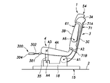
- the seat 1 has a seat back 3 rotatably provided with respect to the floor 2 and a seat cushion 4 rotatably provided with respect to the seat back 3.
- the seat 1 can be in a used state in which the user can sit and in a stored state. In the stored state, the seat back 3 rotates forward from the used state and is arranged substantially horizontally, and the seat cushion 4 moves forward and downward and overlaps with the seat back 3.
- the sheet 1 is a so-called dive-down sheet.
- the seat back 3 has a seat back frame 6 forming a skeleton, a pad supported by the seat back frame 6 (not shown), and a skin material 8 covering the pads.
- the seat cushion 4 has a seat cushion frame 11 forming a skeleton, a pad (not shown) supported by the seat cushion frame 11, and a skin material 13 covering the pad.
- the seat back 3 is supported by the floor 2 via the slide device 15.
- the slide device 15 has left and right lower rails 16 extending back and forth, and left and right upper rails 17 supported by the left and right lower rails 16 so as to be slidable back and forth.
- a rail lock device (not shown) is provided between the left and right lower rails 16 and the corresponding left and right upper rails 17. The position of the upper rail 17 with respect to the lower rail 16 is selectively fixed by the rail lock device.
- a base side member 18 is connected to each of the left and right upper rails 17.
- the left and right base side members 18 extend upward from the corresponding upper rails 17 and extend back and forth.
- the left and right base side members 18 are connected to each other by a plurality of base cross members 19 extending to the left and right.
- the seat back frame 6 has left and right backside members 21 extending vertically, upper members 22 extending left and right and connected to the upper ends of the left and right backside members 21, and left and right backsides extending below the upper members 22. It has a lower member 23 connected to an intermediate portion of the member 21, and a plate-shaped pan frame 24 connected to the left and right backside members 21, an upper member 22, and the rear portion of the lower member 23 with their faces facing forward and backward.
- the lower ends of the left and right backside members 21 are rotatably supported by the corresponding base side members 18 on the left and right sides via the lock device 26, respectively.
- the lower ends of the left and right backside members 21 are rotatably supported by the base side member 18 about the first axis A1 extending to the left and right.
- the upper end of the seat back 3 is the shoulder 3A, the front facing surface is the front 3B, and the rear facing surface is the back 3C.
- the lock device 26 selectively regulates the rotation of the backside member 21 with respect to the base side member 18.
- a known locking device (reclining device) can be applied to the locking device 26.
- the locking device 26 is provided in, for example, a first portion coupled to the base side member 18, a second portion coupled to the backside member 21 and rotatably supported by the base side member 18, and a second portion.
- a lock claw that can move between the coupling position that couples to the first part and the release position away from the first portion, a spring that urges the lock claw to the coupling position, and rotation of the second member with respect to the first member.
- the seat cushion 4 is supported at the rear end portion by an intermediate portion in the vertical direction of the seat back 3.
- the seat cushion frame 11 has left and right cushion side members 31 extending forward and backward, front members 32 extending left and right and connected to the left and right cushion side members 31, and left and right cushion side members extending rearward of the front member 32 left and right. It has a rear member 33 coupled to 31.
- the rear ends of the left and right cushion side members 31 extend rearward from the rear member 33 and bend upward.
- the rear ends of the left and right cushion side members 31 are rotatably supported by the corresponding left and right back side members 21 about the second axis A2 extending to the left and right.
- the front parts of the left and right cushion side members 31 are connected to the front part of the base side member 18 via a link 35, respectively.
- the left and right links 35 are rotatably connected to the corresponding left and right cushion side members 31 about the third axis A3 extending to the left and right. Further, the left and right links 35 are rotatably connected to the corresponding left and right base side members 18 around the fourth axis A4 extending to the left and right.
- the base side member 18, the back side member 21, the cushion side member 31, and the link 35 which correspond to each other on the left and right sides, form a four-section link.
- the front member 32 and the rear member 33 are connected to each other by a pressure receiving member 37.
- the pressure receiving member 37 is formed by a plurality of S-shaped springs.
- the pressure receiving member 37 may be formed of a plate member or a metal wire.
- the ottoman 40 is supported at the front end of the seat cushion 4.
- the ottoman 40 has an ottoman frame 41, a pad supported by the ottoman frame 41 (not shown), and a skin material 43 covering the pad.
- the ottoman frame 41 is rotatably supported by the left and right ends of the first ottoman cross member 45 extending to the left and right and the left and right ends of the first ottoman cross member 45, and the left and right ottoman sides extending in the radial direction of the first ottoman cross member 45. It has a member 46 and a second ottoman cross member 47 extending to the left and right and connected to the tips of the left and right ottoman side members 46.
- Left and right ottoman pillars 48 extending rearward from the first ottoman cross member 45 are provided in the middle portion of the first ottoman cross member 45 in the left-right direction.
- the front member 32 is provided with an ottoman pillar receiving unit 51 that receives the left and right ottoman pillars 48.
- the ottoman 40 is supported by the front member 32 via the ottoman pillar receiving portion 51.
- the ottoman 40 is rotatably supported by the seat cushion 4 about a fourth axis A5 that coincides with the first ottoman cross member 45.
- the ottoman 40 is arranged offset to the left side with respect to the seat cushion 4. Specifically, the left edge of the ottoman 40 is arranged at the same position as the left edge of the seat cushion 4 in the left-right direction. The right edge of the ottoman 40 is offset to the left of the right edge of the seat cushion 4 in the left-right direction.
- An operation lever 28 for releasing the lock device 26 is provided at the right end of the front end portion of the seat cushion 4. When viewed from the front, the operating lever 28 and the ottoman 40 are arranged so as not to overlap each other (see FIG. 8).
- an angle adjusting device 52 is provided between the first ottoman cross member 45 and the left and right ottoman side members 46.
- the angle adjusting device 52 maintains the ottoman side member 46 at an arbitrary angle with respect to the first ottoman cross member 45.
- a known device can be applied to the angle adjusting device 52, for example, the rotation of the ottoman side member 46 is regulated by a frictional force, and the ottoman side member 46 is rotated with respect to the first ottoman cross member 45 when a torque equal to or higher than a predetermined value is applied. It should be a device that allows movement.
- the angle adjusting device 52 has a lock mechanism for restricting the rotation of the ottoman side member 46 with respect to the first ottoman cross member 45, and an operation input unit for receiving the operation of the user, and the operation input unit is operated.
- the locking mechanism may be configured to allow rotation of the ottoman side member 46 with respect to the first ottoman cross member 45.
- a headrest 54 is provided on the upper part of the seat back 3.
- the headrest 54 has a headrest frame 55 forming a skeleton, left and right headrest pillars 56 extending from the headrest frame 55, a pad supported by the headrest frame 55 (not shown), and a skin material 57 covering the pad.
- the headrest frame 55 and the left and right headrest pillars 56 are integrally formed by bending a rod-shaped metal member.
- the upper member 22 is provided with a headrest pillar receiving portion 58 that receives the left and right headrest pillars 56.
- the headrest 54 is supported by the upper member 22 via the headrest pillar receiving portion 58.
- the headrest 54 is supported by the seat back 3 so as to be movable in the vertical direction.
- left and right armrests 61 are rotatably provided on the left and right side portions of the seat back 3.
- the armrest 61 has an armrest frame 62 and a skin material 63 that covers the armrest frame 62.
- a pad may be interposed between the armrest frame 62 and the skin material 63.
- a plate-shaped armrest support portion 64 is connected to an intermediate portion in the longitudinal direction of the left and right backside members 21.
- the left and right armrest support portions 64 are rotatably supported by the armrest frames 62 corresponding to the left and right sides about the fifth axis A6 extending to the left and right.
- the left and right armrests 61 rotate between a use position that protrudes forward from the left and right backside members 21 that extend vertically and a storage position that extends upward along the left and right backside members 21.
- the position of one of the left and right armrests 61 in the left-right direction overlaps with the position of the ottoman 40 in the left-right direction.
- the position of the left armrest 61 in the left-right direction overlaps with the position of the ottoman 40 in the left-right direction.
- the lock device 26 is operated by the control cable and the lock device 26 is released.
- the seat back 3 can rotate with respect to the base side member 18 and the floor 2.
- the seat back 3 rotates forward about the first axis A1.
- the second axis A2 moves forward and downward together with the seat back 3
- the seat cushion 4 moves forward and downward.
- the movement direction of the seat cushion 4 is restricted by the link 35, and the seat cushion 4 moves substantially in parallel.
- the front surface 3B and the back surface 3C of the seat back 3 extend horizontally. Further, the upper surface 4A (seat surface) of the seat cushion 4 extends horizontally and comes into contact with the front surface 3B of the seat back 3.
- the seat cushion 4 and the seat back 3 are in a state of being overlapped with each other in the vertical direction.
- the seat cushion 4 in the stored state is arranged in front of and below the seat cushion 4 in the used state.
- the shoulder portion 3A constituting the front end of the seat back 3 is located in front of the front end of the seat cushion 4.
- the seat back 3 extends forward from the seat cushion 4.
- the left and right ottoman side members 46 rotate with respect to the first ottoman cross member 45, so that the ottoman 40 can rotate with respect to the seat cushion 4.
- the portion where the second ottoman cross member 47 is arranged is referred to as the tip portion 40A
- the portion where the first ottoman cross member 45 is arranged is referred to as the base end portion 40B.
- the ottoman 40 rotates between a lower limit position extending downward from the base end portion 40B to the tip end portion 40A and an upper limit position extending upward from the base end portion 40B to the tip end portion 40A.
- the ottoman 40 may extend vertically downward at the lower limit position and vertically upward at the upper limit position.
- the ottoman 40 may extend upward and backward at the upper limit position.
- the surface arranged on the front side of the ottoman 40 is the support surface 40C.
- the support surface 40C can support the occupant's lower limbs from below.
- the support surface 40C is arranged horizontally and faces upward.
- the support surface 40C may be arranged at the same height as the front end of the upper surface 4A of the seat cushion 4. Further, when the ottoman 40 is in the horizontal position, the support surface 40C may be arranged on the same plane as the upper surface 4A of the seat cushion 4.
- the ottoman 40 When changing the sheet 1 from the used state to the stored state, the ottoman 40 is arranged in the horizontal position by the user. The ottoman 40 is maintained in the lateral position in the process of changing the sheet 1 from the used state to the stored state. As a result, as shown in FIG. 4, the ottoman 40 is arranged in the lateral position when the sheet 1 is in the retracted state.
- the ottoman 40 When the seat 1 is in the stored state, the ottoman 40 is rotatable with respect to the seat cushion 4. The rotation range of the ottoman 40 is regulated by the seat back 3 and the floor 2.
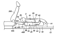
- the tip portion 40A of the ottoman 40 When the seat 1 is in the stowed state and the ottoman 40 is in the lateral position, the tip portion 40A of the ottoman 40 is in front of the shoulder portion 3A (upper end portion) of the seat back 3 and in front of the upper end portion of the headrest 54. Be placed. That is, in the stored state of the seat 1, the support surface 40C of the ottoman 40 projects forward from the seat back 3 and the headrest 54.
- the seat 1 luggage can be placed on the back surface 3C of the seat back 3 in the stored state of the seat 1. Further, since the support surface 40C of the ottoman 40 faces upward and extends forward from the seat back 3, the load can be placed on the support surface 40C of the ottoman 40. That is, the support surface 40C of the ottoman 40 can expand the area on which luggage can be placed. That is, the ottoman 40 functions as an article placing portion, and can place a load on the support surface 40C. Since the ottoman 40 is used as an article placing portion, it is not necessary to attach new parts to the sheet 1. As a result, the sheet 1 can be miniaturized.
- the ottoman 40 By rotating the ottoman 40, it is possible to take an angle suitable for supporting the legs of the seated person and an angle suitable for supporting the luggage. Further, since the ottoman 40 is rotatable with respect to the seat cushion 4 in the stored state of the seat 1, the angle of the ottoman 40 can be changed according to the shape of the luggage after the seat 1 is stored. ..
- the support surface 40C is arranged at the same height as the front end of the upper surface 4A of the seat cushion 4, so that there is a step between the support surface 40C and the back surface 3C of the seat back 3 in the stored state. It can be made smaller.
- the seat back 3 can cover the upper surface A of the seat cushion 4 and protect the upper surface 4A of the seat cushion 4. Further, the back surface 3C of the seat back 3 can be expanded.
- a flexible protective cover 71 is attached to the back surface 3C of the seat back 3.
- the protective cover 71 may have a base end 71A coupled to the back surface 3C of the seat back 3 and a free end 71B.
- the free end 71B of the protective cover 71 may be detachably locked to the back surface 3C of the seat back 3 by a locking member such as a hook-and-loop fastener.
- the width of the protective cover 71 in the left-right direction is preferably substantially equal to the width of the seat back 3 in the left-right direction.
- the protective cover 71 may be folded forward to cover the support surface 40C of the ottoman 40. Thereby, the support surface 40C of the ottoman 40 can be protected by the protective cover 71.
- the seat back 3 rotates forward in a state where the ottoman 40 is tilted upward from the horizontal position, the seat back 3 or the headrest 54 abuts on the ottoman 40, and the rotation of the seat back 3 is restricted. Will be done.
- the sheet 1 is in an intermediate state between the used state and the stored state.
- the seat back 3 is tilted forward and upward.
- a triangular accommodation space 73 defined by the front surface 3B of the seat back 3, the upper surface 4A of the seat cushion 4, and the support surface 40C of the ottoman 40 is formed. Luggage can be placed in the accommodation space 73.
- the ottoman 40 may be arranged so as to extend vertically upward with respect to the seat cushion 4.
- the sheets 1 according to the embodiment may be arranged side by side. As shown in FIG. 8, the sheet 1 according to the embodiment constitutes, for example, the left side sheet 81 in the back row, and the right side sheet 82 on the right side of the left side sheet 81 is symmetrical with respect to the sheet 1 according to the embodiment. Should be placed. It is preferable that the left side sheet 81 and the right side sheet 82 are in contact with each other in the left-right direction. Specifically, the right edge of the seat cushion 4 of the left seat 81 contacts the left edge of the seat cushion 4 of the right seat 82, and the right edge of the seat back 3 of the left seat 81 is the left edge of the seat back 3 of the right seat 82. Is in contact with. By bringing the left side seat 81 and the right side seat 82 into contact with each other, the area where luggage can be placed can be expanded.
- a gap 84 is formed between the ottoman 40 of the left side sheet 81 and the ottoman 40 of the right side sheet 82.
- a gap 84 is maintained between the left and right ottomans 40.
- the luggage can be inserted into the gap 84 between the left and right ottomans 40 to fix the luggage.
- the front end of the ottoman 40 may come into contact with the back of another seat 200 arranged in front.
- the front end of the ottoman 40 may be in contact with the back of the seat cushion or seat back of the other seat 200.
- no space is formed in front of the seat 1 in the stored state, so that it is possible to prevent the luggage from falling in front of the seat 1.
- the other seats may be seats constituting the driver's seat and the passenger seat.
- a cover member 85 may be attached to the ottoman 40.
- the cover member 85 covers the support surface 40C and the back surface 40D of the ottoman 40.
- the cover member 85 is, for example, a flexible sheet 1 material made of resin.
- the cover member 85 is preferably made of a material to which other substances such as dirt do not easily adhere.
- the cover member 85 has a first edge 85A coupled to the front end of the upper surface 4A of the seat cushion 4 and a second edge 85B coupled to the lower portion of the seat cushion 4.
- the first edge 85A may be detachably connected to the front end of the upper surface 4A of the seat cushion 4 by, for example, a wire fastener.
- the cover member 85 extends from the first edge 85A to the tip 40A of the ottoman 40 along the support surface 40C of the ottoman 40, and then extends from the tip 40A of the ottoman 40 to the second edge 85B along the back surface.
- the second edge 85B is connected to the pressure receiving member 37 or the front member from below the seat cushion 4 by an elastic member 86 such as rubber.
- a hook member 87 is provided at the tip of the elastic member 86, and it is preferable that the hook member 87 is hooked on the pressure receiving member 37 or the front member 32. Even if the ottoman 40 rotates, the elastic member 86 allows the cover member 85 to follow the ottoman 40 without loosening.
- the luggage storage space 91 is formed by arranging the ottoman 40 in the upper position rotated upward from the horizontal position.
- the luggage storage space 91 is defined by a seat cushion 4, a seat back 3, an ottoman 40, and left and right armrests 61.
- the luggage storage space 91 is a recess that opens upward.
- the upper position of the ottoman 40 may be the same as the upper limit position of the ottoman 40.
- the tip of the ottoman 40 may be located above the lower edge of the tip of the armrest 61 in the position of use. Further, when the ottoman 40 is in the upper position, the tip of the ottoman 40 may be arranged above the upper edge of the tip of the armrest 61 in the used position.
- the ottoman 40 when the ottoman 40 is in the upper position, the ottoman 40 may be in contact with at least one of the armrests 61 in the used position. That is, the lengths of the ottoman 40 and the armrest 61 are set so that they can come into contact with each other. This makes it difficult for the luggage to fall out between the ottoman 40 and the armrest 61.
- the ottoman 40 may extend rearward and upward from the front end of the seat cushion 4 in the upper position.
- the armrest 61 may be provided with the first movable member 93.
- the first movable member 93 is supported by the armrest 61 so as to be slidable in the longitudinal direction of the armrest 61.
- the first movable member 93 may protrude in the longitudinal direction from the tip end portion of the armrest 61, and the first movable member 93 may abut on the ottoman 40 at the upper position.
- the ottoman 40 may be provided with a second movable member 94.
- the second movable member 94 is rotatably supported by the ottoman 40 about an axis extending to the left and right at the tip of the ottoman 40.
- the second movable member 94 has a left-right width equal to that of the ottoman 40.
- the second movable member 94 may extend rearward from the tip of the ottoman 40 and abut on the armrest 61.
- the first connecting member 96 may be a linear member such as a rope or a rubber string, a planar member such as a woven fabric, a non-woven fabric, or a sheet 1, a net member, or the like.
- the first connecting member 96 is detachably connected to the ottoman 40 and the armrest 61.
- the second connecting member 97 may be a planar member such as a woven fabric, a non-woven fabric, or a sheet 1, a net member, or the like.
- the second connecting member 97 may be formed by, for example, a frame portion and a net portion spanned inside the frame portion.
- the second connecting member 97 is detachably connected to the ottoman 40, the armrest 61, the seat cushion 4, and the seat back 3.
- the ottoman 40 and the armrest 61 may be in contact with each other or may be separated from each other in a state where the ottoman 40, the armrest 61, the seat cushion 4, and the seat back 3 are connected by the second connecting member 97. Further, even if the tip of the ottoman 40 is arranged above the lower edge of the tip of the armrest 61 in a state where the ottoman 40, the armrest 61, the seat cushion 4, and the seat back 3 are connected by the second connecting member 97. It may be placed below.
- the first connecting member 96 and the second connecting member 97 prevent the luggage arranged in the luggage storage space 91 from falling off to the left and right.
- the box body 101 may be placed on the floor 2 instead of the ottoman 40, and the box body 101 may be used as an article placing portion.
- the box body 101 is removable with respect to the floor 2 and may be arranged in front of the seat cushion 4.
- the upper surface of the box body 101 may form a support surface.
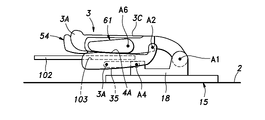
- a support plate 102 may be provided on the seat cushion 4 so as to be slidable back and forth.
- the support plate 102 may be pulled out to the front of the seat cushion 4 to form an article placing portion.
- a slot 103 for receiving the support plate 102 is formed at the front end of the seat cushion 4. When the sheet 1 is in use, the support plate 102 may be received in the slot 103.
- the slide device 15 may be omitted.
- the base side member 18 may be directly coupled to the floor 2. That is, the seat back 3 may be directly rotatably provided on the floor 2 or may be indirectly rotatably provided on the floor 2 via the slide device 15.
- the seat cushion 4 may be supported on the floor 2 and the seat back 3 may be rotatably supported by the seat cushion.
- the slide device 15 may be interposed between the floor 2 and the seat cushion 4.
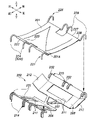
- the pressure receiving member 37 may have a sheet-shaped member 201 and a support member 202 instead of the S-shaped spring.
- the support member 202 extends back and forth and is hung between the middle member 204 and the rear member 33.
- the middle member 204 extends to the left and right behind the front member 32 and is connected to the left and right cushion side members 31.
- the support member 202 has a surface facing up and down, and its leading edge and trailing edge extend to the left and right.
- the support member 202 has flexibility and is formed of, for example, resin.
- the support member has a front portion 206, an intermediate portion 207, and a rear portion 208 in this order from the front side.
- the support member 202 is supported by the middle member 204 at the front 206 and by the rear member 33 at the rear 208.
- the intermediate portion 207 extends substantially horizontally, the front portion 206 extends forward and upward from the intermediate portion 207 toward the front member 32, and the rear portion 208 extends rearward and upward toward the rear member 33 from the intermediate portion 207. ..
- the left-right width of the intermediate portion 207 may be set smaller than the left-right width of each of the front portion 206 and the rear portion 208.
- the intermediate portion 207 is formed in a triangular shape and has a smaller left-right width toward the front.
- each of the front portion 206 and the rear portion 208 is formed in a substantially rectangular shape.
- the left-right width of the front portion 206 is formed smaller than the left-right width of the rear portion 208. It is preferable that at least one lightening hole 211 is formed in each of the front portion 206, the intermediate portion 207, and the rear portion 208.
- the shapes of the front portion 206, the intermediate portion 207, the rear portion 208, and the lightening hole 211 can be arbitrarily set.
- the right and left portions of the rear portion 208 are provided with left and right extension pieces 212 extending laterally and upward from the side edges of the rear portion 208.
- the left and right extension pieces 212 extend above the cushion side member 31.
- a plurality of first hook portions 214 that are hooked on the middle member 204 are provided on the leading edge of the front portion 206 of the support member 202.
- Each of the first hook portions 214 is formed in a semicircular shape that opens downward when viewed from the left-right direction.
- a second hook portion 215 that is hooked on the rear member 33 is provided on the trailing edge of the rear portion 208 of the support member 202.
- the second hook portion 215 extends to the left and right along the trailing edge of the rear portion 208 of the support member 202.
- the second hook portion 215 is formed in a semicircular shape that opens downward when viewed from the left-right direction.
- the support member 202 is hung between the middle member 204 and the rear member 33 by hooking the plurality of first hook portions 214 to the middle member rear member and hooking the second hook portion 215 to the rear member 33.
- the sheet-shaped member 201 is bridged between the middle member 204 and the rear member 33. At least one front locking portion 221 is provided on the leading edge of the sheet-shaped member 201.
- the front locking portion 221 is formed by bending a metal rod.
- a plurality of front loop portions 222 are formed by folding back and suturing the leading edge of the sheet-shaped member 201. Each front loop portion 222 extends to the left and right.
- the front locking portion 221 has a shaft portion 223 rotatably supported by the front loop portion 222, and left and right third hook portions 224 extending forward from both ends of the shaft portion 223.
- the third hook portion 224 is formed in a semicircular shape that opens downward when viewed from the left-right direction.
- At least one rear locking portion 226 is provided on the trailing edge of the sheet-like member 201.
- the rear locking portion 226 is formed by bending a metal rod.
- the trailing edge of the sheet-like member 201 is folded back and sewn to form a plurality of posterior loop portions 227.
- Each rear loop portion 227 extends to the left and right.
- the rear locking portion 226 has a shaft portion 228 rotatably supported by the rear loop portion 227, and left and right fourth hook portions 229 extending forward from both ends of the shaft portion 228.
- the fourth hook portion 229 is formed in a semicircular shape that opens downward when viewed from the left-right direction.
- the front locking portion 221 of the sheet-shaped member 201 is locked to the first hook portion 214 of the support member 202, and is locked to the middle member 204 via the first hook portion 214.
- a front engaging groove 231 for receiving the third hook portion 224 is formed on the upper surface of the first hook portion 214 of the support member 202.
- the front engaging groove 231 extends back and forth along the upper surface of the first hook portion 214.
- the rear locking portion 226 of the sheet-shaped member 201 is locked to the second hook portion 215 of the support member 202, and is locked to the rear member 33 via the second hook portion 215.
- a rear engaging groove 232 for receiving the fourth hook portion 229 is formed on the upper surface of the second hook portion 215 of the support member 202.
- the rear engaging groove 232 extends back and forth along the upper surface of the second hook portion 215.
- the central portion 301C in the front-rear direction of the seat-shaped member 201 is located at a position away from the intermediate portion 207 of the support member 202.
- the seat-shaped member 201 bends downward, and the seat-shaped member 201 is supported by the upper surface of the support member 202.
- the hook member 87 connected to the end of the cover member 85 via the elastic member 86 may be locked to the support member 202.
- the hook member 87 may be locked to the trailing edge of the front portion 206 of the support member 202 or the hole edge of the lightening hole 211.
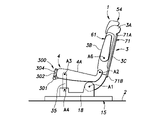
- an article placing portion 300 may be provided at the front end of the seat cushion 4 instead of the ottoman 40.
- the article placing portion 300 includes a rotation shaft 301 extending to the left and right at the front end of the seat cushion 4, a left and right support shaft 302 rotatably supported by the rotation shaft 301, and extending in the radial direction of the rotation shaft 301. It has a plate member 304 that is slidably supported on the left and right support shafts 302.
- the rotating shaft 301 is provided at the lower part of the front end of the seat cushion.
- the left and right support shafts 302 rotate between a lateral position extending forward from the front end of the seat cushion and a vertical position extending upward from the front end of the seat cushion.
- the plate member 304 is provided along a plane including the left and right support shafts 302. When the support shaft 302 is in the horizontal position, the surface of the plate member 304 faces up and down, and when the support shaft 302 is in the vertical position, the surface of the plate member 304 faces back and forth.
- the plate member 304 is provided on the left and right support shafts 302 so as to be slidable in the extending direction of the support shafts 302. The plate member 304 moves between a contraction position located on the proximal end side of the support shaft 302 and an extension position located on the distal end side of the support shaft 302.
- FIG. 21 shows a state in which the support shaft 302 is in the vertical position and the plate member 304 is in the contracted position. In this state, the plate member 304 is arranged along the front end of the seat cushion. At this time, the occupant can sit on the seat.
- FIG. 22 shows a state in which the support shaft 302 is in the vertical position and the plate member 304 is in the extended position.
- the plate member 304 projects upward from the front end of the seat cushion.
- the plate-shaped member can prevent the luggage arranged on the seat cushion 4 from falling forward.
- FIG. 23 shows a state in which the support shaft 302 is in the horizontal position and the plate member 304 is in the extended position. In this state, the plate member 304 extends forward from the front end of the seat cushion. At this time, the plate-shaped member can support the luggage in front of the seat cushion 4.
- a plurality of vibrators 400 may be provided on the seat cushion 4.
- the vibrator 400 may have an electric motor and an eccentric weight coupled to the drive shaft of the electric motor.
- the vibrator 400 generates vibration by rotating the electric motor.
- the plurality of vibrators 400 are provided on the occupant-side surface (upper surface) of the pad 401 of the seat cushion 4, that is, between the pad 401 and the skin material 13.
- the plurality of vibrators 400 include a first group 400A arranged on the center side in the left-right direction (width direction) of the seat cushion 4, and a second group 400B arranged on the left and right end sides of the seat cushion 4 in the left-right direction. including.
- the seat cushion 4 has a flat portion 4B arranged in the central portion in the left-right direction and left and right raised portions 4C arranged on the left and right outer sides of the flat portion 4B.
- the flat portion 4B is formed on a flat surface facing upward.
- the left and right raised portions 4C project upward with respect to the flat portion 4B.
- a plurality of vibrators 400 included in the first group 400A are arranged at the center of the flat portion 4B in the left-right direction, and a plurality of vibrators 400 included in the second group 400B are arranged at both left and right ends of the flat portion 4B in the left-right direction. ing.
- the plurality of vibrators 400 included in the first group 400A may be arranged in the flat portion 4B
- the plurality of vibrators 400 included in the second group 400B may be arranged in the left and right raised portions 4C.
- the plurality of vibrators 400 are connected to the control device 404.
- the control device 404 vibrates at least one vibrator 400 selected from the plurality of vibrators 400 when a predetermined notification condition is satisfied.
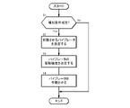
- the control device 404 may control a plurality of vibrators 400 according to the procedure shown in FIG. 25, for example. First, the control device 404 determines whether or not the notification condition is satisfied (S1).
- the notification conditions can be arbitrarily set. For example, whether or not the lateral acceleration of the vehicle provided with the seat 1 is equal to or higher than a predetermined value, and whether or not the longitudinal acceleration of the vehicle provided with the seat 1 is equal to or higher than a predetermined value. It may include whether or not the automatic driving of the vehicle provided with the seat 1 is about to end, whether or not there is an obstacle within a predetermined range from the vehicle provided with the seat 1, and the like.
- the control device 404 selects the vibrator 400 to be operated from the plurality of vibrators 400 (S2).
- the control device 404 may select the vibrator 400 to be operated from among the plurality of vibrators 400 based on the signal from the occupant information acquisition device 405.
- the occupant information acquisition device 405 may include at least one of a camera that images an occupant seated on the seat 1 and a load sensor provided on the seat cushion 4 or the seat back 3.
- the control device 404 may specify the size of the occupant based on the image of the occupant captured by the camera as the occupant information acquisition device 405. Further, the control device 404 may specify the size of the occupant based on the load detected by the load sensor as the occupant information acquisition device 405.
- the control device 404 may select the vibrator 400 to be operated based on the size of the occupant.
- the control device 404 may increase the number of vibrators 400 to be operated as the size of the occupant increases.
- the control device 404 operates, for example, all the vibrators 400 included in the first group 400A and the second group 400B when the size of the occupant is equal to or larger than the predetermined value, and when the size of the occupant is less than the predetermined value, the first control device 404 operates. It is preferable to operate only the vibrator 400 included in one group 400A.
- control device 404 may be connected to the input device 407 that accepts the input operation of the user, and may select the vibrator 400 to be operated based on the selection information input to the input device 407.
- the input device 407 may be, for example, a touch panel display provided on the vehicle.
- the control device 404 determines the vibration intensity of the selected vibrator 400 (S3).
- the vibration intensity of the vibrator 400 changes according to the increase or decrease in the rotation speed of the electric motor included in the vibrator 400.
- the control device 404 estimates, for example, the thickness of the user's clothes from the time and the image of the user captured by the camera, and it is preferable that the thicker the clothes, the higher the vibration intensity of the vibrator 400.
- the thickness of the clothes is classified into three levels of thin, medium, and thick, and the vibration intensity of the vibrator 400 may be changed according to the level of the thickness of the clothes.
- the control device 404 acquires the date, determines that the thickness of the clothes is thin when the date corresponds to the summer, determines that the thickness of the clothes corresponds to the spring or autumn, and the date corresponds to the winter. When corresponding, it is advisable to judge that the thickness of the clothes is thick.
- the control device 404 vibrates the vibrator 400 selected in step S2 with the vibration intensity selected in step S3 (S4).
- the vibrator 400 arranged in the range corresponding to the user seated on the seat 1 operates.
- the power consumption can be reduced.
- the vibration intensity of the vibrator 400 increases or decreases according to the thickness of the clothes of the user, the vibrator 400 can reliably notify the user regardless of the thickness of the clothes.
- a plurality of load sensors 408 may be dispersedly arranged on the upper surface 4A of the seat cushion 4.
- the control device 404 may acquire the load distribution on the upper surface 4A of the seat cushion 4 based on the loads acquired by the plurality of load sensors 408. Then, in step S2, the control device 404 may select at least one vibrator 400 arranged in at least one region where the load is equal to or more than a predetermined value as the vibrator 400 to be operated. Further, the control device 404 may set the vibration intensity of the vibrator 400 based on the load distribution in step S3. The control device 404 may make the vibration intensity of the vibrator 400 arranged in the region where the load is high larger than the vibration intensity of the vibrator 400 arranged in the region where the load is low.
- a vibrator 400 may be provided on the seat back 3, and each vibrator 400 of the seat back 3 may be controlled by the control device 404.
- a plurality of vibrators 400 may be symmetrically arranged on the seat back 3 and the seat cushion 4, and only one of the left and right vibrators 400 may be operated.
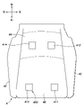
- the first to fourth vibrators 411 to 414 are arranged on the seat cushion 4.
- the first vibrator 411 is located at the front and left of the seat cushion 4
- the second vibrator 412 is located at the rear and left of the seat cushion 4
- the third vibrator 413 is located at the front and right of the seat cushion 4.
- the fourth vibrator 414 is arranged at the rear and right side of the seat cushion 4.
- the first vibrator 411 and the third vibrator 413 are arranged at positions symmetrical with each other
- the second vibrator 412 and the fourth vibrator 414 are arranged at positions symmetrical with each other.
- the control device 404 activates the first vibrator 411 and the second vibrator 412 when the left alert request is generated, and the third vibrator 413 and the fourth vibrator 414 when the right alert request is generated. Activate.
- the control device 404 may generate a left alert request when, for example, the lateral acceleration sensor determines that the vehicle is turning to the left based on a signal. Further, when the control device 404 determines from the acceleration sensor that the vehicle is turning to the right side based on the signal, the control device 404 may generate a warning request on the right side. In another embodiment, only a pair of vibrators 400 may be arranged on the left and right sides.
- the first vibrator 421 is arranged at the rear portion of the seat cushion 4 and at the central portion in the left-right direction.
- the second vibrator 422 is arranged at the front portion and the left portion of the seat cushion 4.
- the third vibrator 423 is arranged at the front portion and the right portion of the seat cushion 4.
- the first vibrator 421 is arranged at a position corresponding to the user's buttocks
- the second vibrator 422 is arranged at a position corresponding to the user's left thigh
- the third vibrator 423 is arranged at the user's right thigh. It is located in the corresponding position.
- the control device 404 may operate the first vibrator 421 when generating the alert request on the left side, and operate the second vibrator 422 after a predetermined delay time. Further, the control device 404 may operate the first vibrator 421 when generating the alert request on the right side, and may operate the third vibrator 423 after a predetermined delay time.
- the vibrator 400 to be operated may be changed according to the rotation position of the seat 1.
- the sheet 1 rotates about a rotation axis and may have a forward facing position facing forward and a backward facing position facing backward.
- the control device 404 may determine whether or not the seat 1 is in the forward position (S11). When the seat 1 is in the forward position (the determination result of S11 is Yes), the control device 404 operates the first vibrator 411 and the second vibrator 412 arranged on the left side of the seat cushion 4 in response to the alert request on the left side.
- the third vibrator 413 and the fourth vibrator 414 arranged on the right side of the seat cushion 4 are operated in response to the alert request on the right side (S12).
- the control device 404 responds to the alert request on the left side with the third vibrator 413 and the third vibrator 413 arranged on the right side arranged on the left side of the seat cushion 4. 4
- the vibrator 414 is operated, and the first vibrator 411 and the second vibrator 412 arranged on the right side of the seat cushion 4 are operated in response to the alert request on the right side (S12).
- a device that generates sound, scent, light, or the like may be provided.
- a device that transmits information to the user of the sheet 1 by generating at least one of vibration, sound, scent, and light is defined as an information transmission device.
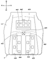
- a first receiving hole 432 and a second receiving hole 433 for receiving various devices 431 are formed on the front surface of the pad 430 of the seat back 3 facing the occupant side.
- the first receiving hole 432 and the second receiving hole 433 are bottomed holes that open toward the front.
- the first receiving hole 432 is formed in the upper part of the pad 430
- the second receiving hole 433 is formed in the lower part of the pad 430.
- the first receiving hole 432 and the second receiving hole 433 are each formed in a rectangular shape when viewed from the front.
- a third receiving hole 434, a fourth receiving hole 435, and a fifth receiving hole 436 for receiving various devices 431 are formed on the upper surface of the pad 401 of the seat cushion 4 facing the occupant side. It is formed.
- the third receiving hole 434, the fourth receiving hole 435, and the fifth receiving hole 436 are bottomed holes that open upward.
- the third receiving hole 434 is formed in the center of the rear part of the pad 401 in the left-right direction
- the fourth receiving hole 435 is formed on the front left side of the pad 401
- the fifth receiving hole 436 is formed on the front right side of the pad 401.
- the third receiving hole 434, the fourth receiving hole 435, and the fifth receiving hole 436 are each formed in a rectangular shape when viewed from above.
- Each device 431 includes a case forming an outer shape and an electric device received in the case.
- the case of each device 431 may be formed in the same shape. In this embodiment, the case of each device 431 is formed into a rectangular parallelepiped of the same size.
- the device 431 constitutes at least one of a vibrator, a sensor, and a temperature controller.
- the sensor may include, for example, at least one of a load sensor, a heart rate sensor, a temperature sensor, a humidity sensor, and an acceleration sensor.
- the temperature controller may include at least one of an electric heating device, a cooling device including a Pelche element, and a fan.
- Each device 431 may have a plurality of functions.
- the device 431 may be a combination of at least two of a vibrator, a sensor, and a temperature controller.
- the device 431 may include a vibrator and a sensor located on the outer surface of the vibrator.
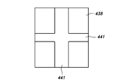
- Each of the first to fifth receiving holes 432 to 436 is formed to a size that can accept at least one device 431. Further, spacers 438 for filling the gaps between the first to fifth receiving holes 432 to 436 are arranged in each of the first to fifth receiving holes 432 to 436.
- the spacer 438 may be made of the same material as the pads 401 and 430.
- the sizes of the first to fifth receiving holes 432 to 436 are formed to be an integral multiple of the size of one device 431.
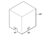
- the spacer 438 may be formed in the same shape as the case of the device 431. Thereby, an arbitrary number of devices 431 and spacers 438 are inserted into the first to fifth receiving holes 432 to 436, respectively, thereby filling each of the first to fifth receiving holes 432 to 436.
- the first receiving hole 432 is formed to be three times as large as the device 431 and receives two devices 431 and one spacer 438.
- the two devices 431 may have the same function or may have different functions.
- the third receiving hole 434 is not formed to be an integral multiple of the device 431. Therefore, in order to fill the gap between the third receiving hole 434 and the two devices 431, two or more types of spacers 438 having different shapes are used.
- the spacer 438 has a harness groove 441 that receives the wire harness 439 extending from the device 431.
- the harness groove 441 may be formed on the bottom surface of the spacer 438, that is, the surface in contact with the bottom surfaces of the first to fifth receiving holes 432 to 436.
- a plurality of harness grooves 441 may be provided in the spacer 438, and may have two harness grooves 441 that intersect each other, for example.
- the harness groove 443 may be formed at the bottom of the third receiving hole 434.
- the pads 401 and 430 are formed with harness holes 442 adjacent to the first to fifth receiving holes 432 to 436.
- the harness hole 442 penetrates the pads 401 and 430 in the thickness direction.
- the wire harness 439 passes through the harness hole 442 and extends to the back surface side of the pads 401 and 430.
- the harness hole 442 is provided adjacent to the third receiving hole 433. Further, a connecting groove 447 connecting the fourth receiving hole 435 and the fifth receiving hole 436 may be formed, and the harness hole 442 may be formed at the bottom of the connecting groove 447.
- a plurality of ventilation holes 444 may be formed at the bottoms of the first to fifth receiving holes 432 to 436, respectively.
- the plurality of ventilation holes 444 may penetrate the pads 401 and 430 in the thickness direction. Further, the plurality of ventilation holes 444 may communicate with the air passage 445 formed in the pads 401 and 430.
- the air passage 445 may be provided with a blower 446.
- the spacer 438 arranged at the position corresponding to the ventilation hole 444 may be breathable.
- the spacer 438 may have, for example, at least one through hole penetrating in the thickness direction. Further, the spacer 438 is preferably formed of a highly breathable porous body.
- the skin material 8 of the seat back 3 has a first opening 451 for exposing the first receiving hole 432 to the outside and a second opening for exposing the second receiving hole 433 to the outside. 452 and are formed.
- the first opening 451 is covered by a first cover 453 that is detachably coupled to the skin material 8.
- the second opening 452 is covered by a second cover 454 that is detachably coupled to the skin material 8.
- Each of the first cover 453 and the second cover 454 may be inseparably bonded to the skin material 8 in part.
- the skin material 8 is arranged between the first opening 451 and the second opening 452, and has a cover fixing portion 455 extending to the left and right.
- the lower edge of the first cover 453 and the upper edge of the second cover 454 are coupled to the cover fixing portion 455.
- the left and right side edges and the lower edge of the first cover 453 are detachably connected to the edge portion of the first opening 451 by a fastener 457.
- the left and right side edges and lower edges of the second cover 454 are detachably coupled to the edge of the second opening 452 by fasteners 458.
- the third opening 461 for exposing the third receiving hole 434 to the outside, and the fourth receiving hole 435 and the fifth receiving hole 436 are exposed to the outside.
- a fourth opening 462 is formed for this purpose.
- the third opening 461 is covered by a third cover 463 that is detachably coupled to the skin material 13.
- the fourth opening 462 is covered by a fourth cover 464 that is detachably coupled to the skin material 13.
- Each of the third cover 463 and the fourth cover 464 may be inseparably bonded to the skin material 13 in part.
- the skin material 13 is arranged between the third opening 461 and the fourth opening 462, and has a cover fixing portion 465 extending to the left and right.
- the leading edge of the third cover 463 and the trailing edge of the fourth cover 464 are coupled to the cover fixing portion 465.
- the left and right side edges and trailing edges of the third cover 463 are detachably coupled to the edges of the third opening 461 by fasteners 467.
- the left and right side edges and leading edges of the fourth cover 464 are detachably coupled to the edges of the fourth opening 462 by fasteners 468.
- the first to fifth receiving holes 432 to 436 can be exposed by opening the first to fourth covers 453, 454, 463, 464. This facilitates the change and position change of the device 431.
- other removable coupling members such as snap buttons may be used in place of the fasteners 458 and 468.
Landscapes
- Engineering & Computer Science (AREA)
- Mechanical Engineering (AREA)
- Aviation & Aerospace Engineering (AREA)
- Transportation (AREA)
- Passenger Equipment (AREA)
- Seats For Vehicles (AREA)
Priority Applications (4)
| Application Number | Priority Date | Filing Date | Title |
|---|---|---|---|
| JP2022559450A JP7787422B2 (ja) | 2020-11-02 | 2021-11-01 | 乗物用シート |
| US18/034,804 US12337734B2 (en) | 2020-11-02 | 2021-11-01 | Vehicle seat |
| US19/206,840 US20250269774A1 (en) | 2020-11-02 | 2025-05-13 | Vehicle seat |
| JP2025225886A JP2026026301A (ja) | 2020-11-02 | 2025-12-03 | 乗物用シート |
Applications Claiming Priority (6)
| Application Number | Priority Date | Filing Date | Title |
|---|---|---|---|
| US202063198653P | 2020-11-02 | 2020-11-02 | |
| US63/198,653 | 2020-11-02 | ||
| US202063198889P | 2020-11-20 | 2020-11-20 | |
| US63/198,889 | 2020-11-20 | ||
| JP2021047186 | 2021-03-22 | ||
| JP2021-047186 | 2021-03-22 |
Related Child Applications (2)
| Application Number | Title | Priority Date | Filing Date |
|---|---|---|---|
| US18/034,804 A-371-Of-International US12337734B2 (en) | 2020-11-02 | 2021-11-01 | Vehicle seat |
| US19/206,840 Continuation US20250269774A1 (en) | 2020-11-02 | 2025-05-13 | Vehicle seat |
Publications (1)
| Publication Number | Publication Date |
|---|---|
| WO2022092314A1 true WO2022092314A1 (ja) | 2022-05-05 |
Family
ID=81382684
Family Applications (1)
| Application Number | Title | Priority Date | Filing Date |
|---|---|---|---|
| PCT/JP2021/040260 Ceased WO2022092314A1 (ja) | 2020-11-02 | 2021-11-01 | 乗物用シート |
Country Status (3)
| Country | Link |
|---|---|
| US (2) | US12337734B2 (https=) |
| JP (2) | JP7787422B2 (https=) |
| WO (1) | WO2022092314A1 (https=) |
Cited By (1)
| Publication number | Priority date | Publication date | Assignee | Title |
|---|---|---|---|---|
| WO2024071268A1 (ja) | 2022-09-28 | 2024-04-04 | テイ・エス テック株式会社 | 制御ユニット、姿勢改善支援装置、及び制御方法 |
Families Citing this family (2)
| Publication number | Priority date | Publication date | Assignee | Title |
|---|---|---|---|---|
| KR20230093585A (ko) * | 2021-12-20 | 2023-06-27 | 현대자동차주식회사 | 자동차용 시트 |
| US20250325111A1 (en) * | 2024-04-22 | 2025-10-23 | Secretlab Sg Pte. Ltd. | Assembly system for attaching an accessory to a furniture item |
Citations (6)
| Publication number | Priority date | Publication date | Assignee | Title |
|---|---|---|---|---|
| US3982787A (en) * | 1974-01-11 | 1976-09-28 | Maschinenfabrik Augsburg-Nurnberg Ag | Seat arrangement for a passenger car |
| JP2005306357A (ja) * | 2004-04-22 | 2005-11-04 | Hyundai Motor Co Ltd | 自動車用リヤシートバックのバックボード展開構造 |
| DE102004019894A1 (de) * | 2004-04-23 | 2005-11-24 | Volkswagen Ag | Sitzanordnung |
| JP3173395U (ja) * | 2011-11-24 | 2012-02-02 | 株式会社ジェーピー | 補助シートクッション |
| JP2017177865A (ja) * | 2016-03-28 | 2017-10-05 | アイシン精機株式会社 | 車両用オットマン装置 |
| JP2019001242A (ja) * | 2017-06-13 | 2019-01-10 | トヨタ紡織株式会社 | 乗物用シート |
Family Cites Families (11)
| Publication number | Priority date | Publication date | Assignee | Title |
|---|---|---|---|---|
| JP5119910B2 (ja) * | 2007-12-26 | 2013-01-16 | トヨタ紡織株式会社 | 車両用シート |
| WO2010086822A1 (en) * | 2009-01-30 | 2010-08-05 | Air New Zealand Limited | A vehicle seat with reclining back and leg rest |
| JP5719280B2 (ja) | 2011-11-25 | 2015-05-13 | 本田技研工業株式会社 | 車両用シート装置 |
| JP6315985B2 (ja) * | 2013-12-27 | 2018-04-25 | テイ・エス テック株式会社 | 乗物用シート |
| GB2550608B (en) * | 2016-05-25 | 2020-09-09 | Ford Global Tech Llc | A motor vehicle and a multi-functional cover for same |
| US10479225B2 (en) * | 2016-10-18 | 2019-11-19 | Ford Global Technologies, Llc | Method of configuring a vehicle seating assembly |
| US11697362B2 (en) * | 2018-07-13 | 2023-07-11 | Ts Tech Co., Ltd. | Conveyance seat |
| CN110254314B (zh) * | 2019-06-25 | 2020-06-16 | 延锋安道拓座椅有限公司 | 内藏式座椅腿托及座椅 |
| US11234526B1 (en) * | 2020-05-27 | 2022-02-01 | Eric Martin Levin | Chair configured for progressive reclination and conversion between multiple use and/or storage positions, and a method of use thereof |
| US10980347B1 (en) * | 2020-05-27 | 2021-04-20 | Eric Martin Levin | Chair configured for progressive reclination and conversion between multiple use and/or storage positions, and a method of use thereof |
| US12427898B2 (en) * | 2021-03-30 | 2025-09-30 | Ts Tech Co., Ltd. | Vehicle seat |
-
2021
- 2021-11-01 WO PCT/JP2021/040260 patent/WO2022092314A1/ja not_active Ceased
- 2021-11-01 US US18/034,804 patent/US12337734B2/en active Active
- 2021-11-01 JP JP2022559450A patent/JP7787422B2/ja active Active
-
2025
- 2025-05-13 US US19/206,840 patent/US20250269774A1/en active Pending
- 2025-12-03 JP JP2025225886A patent/JP2026026301A/ja active Pending
Patent Citations (6)
| Publication number | Priority date | Publication date | Assignee | Title |
|---|---|---|---|---|
| US3982787A (en) * | 1974-01-11 | 1976-09-28 | Maschinenfabrik Augsburg-Nurnberg Ag | Seat arrangement for a passenger car |
| JP2005306357A (ja) * | 2004-04-22 | 2005-11-04 | Hyundai Motor Co Ltd | 自動車用リヤシートバックのバックボード展開構造 |
| DE102004019894A1 (de) * | 2004-04-23 | 2005-11-24 | Volkswagen Ag | Sitzanordnung |
| JP3173395U (ja) * | 2011-11-24 | 2012-02-02 | 株式会社ジェーピー | 補助シートクッション |
| JP2017177865A (ja) * | 2016-03-28 | 2017-10-05 | アイシン精機株式会社 | 車両用オットマン装置 |
| JP2019001242A (ja) * | 2017-06-13 | 2019-01-10 | トヨタ紡織株式会社 | 乗物用シート |
Cited By (1)
| Publication number | Priority date | Publication date | Assignee | Title |
|---|---|---|---|---|
| WO2024071268A1 (ja) | 2022-09-28 | 2024-04-04 | テイ・エス テック株式会社 | 制御ユニット、姿勢改善支援装置、及び制御方法 |
Also Published As
| Publication number | Publication date |
|---|---|
| JPWO2022092314A1 (https=) | 2022-05-05 |
| US20230406171A1 (en) | 2023-12-21 |
| US12337734B2 (en) | 2025-06-24 |
| JP7787422B2 (ja) | 2025-12-17 |
| US20250269774A1 (en) | 2025-08-28 |
| JP2026026301A (ja) | 2026-02-16 |
Similar Documents
| Publication | Publication Date | Title |
|---|---|---|
| WO2022092314A1 (ja) | 乗物用シート | |
| US8608243B2 (en) | Vehicle seat | |
| JP6547433B2 (ja) | 移動調整システム | |
| CN111469730B (zh) | 用于模块化车辆座椅等的车辆座椅衬垫托架组件 | |
| US10166894B2 (en) | Seatback comfort carrier | |
| WO2022158546A1 (ja) | 乗物用シート | |
| WO2022210892A1 (ja) | 乗物用シート | |
| JP7587175B2 (ja) | 車両用シート | |
| CN113022394B (zh) | 用于设置在机动车中的儿童约束系统的儿童座椅垫子 | |
| JP5365219B2 (ja) | 車両用シート | |
| US8052214B2 (en) | Seat structure | |
| WO2017094334A1 (ja) | シート | |
| JP2023152049A (ja) | 乗物用シート | |
| JP7523136B2 (ja) | 落下防止具 | |
| JP5343422B2 (ja) | 乗物用シートの着せ替えカバー | |
| JPH0350051A (ja) | 自動車の座席利用者倒伏防止ガード | |
| JP5884684B2 (ja) | 車両用シート | |
| JP5343423B2 (ja) | 乗物用シートの着せ替えカバー | |
| JP6829403B2 (ja) | 車両 | |
| JP2026059829A (ja) | ランバーサポート可能な車両のシート装置 | |
| JP2010142365A (ja) | 着座姿勢調整装置 | |
| JP3535272B2 (ja) | 多機能シートバック装置 | |
| WO2024262586A1 (ja) | 車両用シート | |
| JPH0520196Y2 (https=) | ||
| JP6643046B2 (ja) | 椅子の体圧支持装置 |
Legal Events
| Date | Code | Title | Description |
|---|---|---|---|
| 121 | Ep: the epo has been informed by wipo that ep was designated in this application |
Ref document number: 21886431 Country of ref document: EP Kind code of ref document: A1 |
|
| ENP | Entry into the national phase |
Ref document number: 2022559450 Country of ref document: JP Kind code of ref document: A |
|
| NENP | Non-entry into the national phase |
Ref country code: DE |
|
| 122 | Ep: pct application non-entry in european phase |
Ref document number: 21886431 Country of ref document: EP Kind code of ref document: A1 |
|
| WWG | Wipo information: grant in national office |
Ref document number: 18034804 Country of ref document: US |