WO2022080302A1 - 満タン規制バルブ - Google Patents
満タン規制バルブ Download PDFInfo
- Publication number
- WO2022080302A1 WO2022080302A1 PCT/JP2021/037537 JP2021037537W WO2022080302A1 WO 2022080302 A1 WO2022080302 A1 WO 2022080302A1 JP 2021037537 W JP2021037537 W JP 2021037537W WO 2022080302 A1 WO2022080302 A1 WO 2022080302A1
- Authority
- WO
- WIPO (PCT)
- Prior art keywords
- flow hole
- fuel
- hole
- valve
- fuel tank
- Prior art date
- Legal status (The legal status is an assumption and is not a legal conclusion. Google has not performed a legal analysis and makes no representation as to the accuracy of the status listed.)
- Ceased
Links
Images


Classifications
-
- B—PERFORMING OPERATIONS; TRANSPORTING
- B60—VEHICLES IN GENERAL
- B60K—ARRANGEMENT OR MOUNTING OF PROPULSION UNITS OR OF TRANSMISSIONS IN VEHICLES; ARRANGEMENT OR MOUNTING OF PLURAL DIVERSE PRIME-MOVERS IN VEHICLES; AUXILIARY DRIVES FOR VEHICLES; INSTRUMENTATION OR DASHBOARDS FOR VEHICLES; ARRANGEMENTS IN CONNECTION WITH COOLING, AIR INTAKE, GAS EXHAUST OR FUEL SUPPLY OF PROPULSION UNITS IN VEHICLES
- B60K15/00—Arrangement in connection with fuel supply of combustion engines or other fuel consuming energy converters, e.g. fuel cells; Mounting or construction of fuel tanks
- B60K15/03—Fuel tanks
- B60K15/077—Fuel tanks with means modifying or controlling distribution or motion of fuel, e.g. to prevent noise, surge, splash or fuel starvation
Definitions
- the present invention relates to a full tank control valve that enables additional refueling.
- the fuel tank may be equipped with a full tank regulation valve that detects when the fuel is full and closes it to prevent overfueling.
- a communication hole for communicating an upper space, a lower chamber, an upper space and a lower chamber, and a communication hole which rises due to fuel inflow into the lower chamber and closes the communication hole is provided.
- the lower chamber is provided with a main inflow portion of fuel only on the side thereof, and the inflow of fuel into the lower chamber after the liquid level level of the fuel in the fuel tank reaches the main inflow portion is provided.
- An overfuel prevention valve that raises the internal pressure of the fuel tank to detect full tank is described.
- the casing body and the cup body arranged below the casing body are provided, and the cup body has an opening at the upper side and is more than the casing body. Is also expanded in diameter, and a main inflow portion is provided between the lower edge portion of the casing body and the upper edge portion of the cup body. Further, a side orifice is formed below the casing body.
- an object of the present invention is to provide a full tank regulation valve capable of promptly performing additional refueling after the full tank regulation is made.
- the full tank control valve has a peripheral wall and a partition wall, and the valve chamber communicating downward into the fuel tank and the outside of the fuel tank above through the partition wall.
- a ventilation chamber is provided, and an opening for communicating the valve chamber and the ventilation chamber is formed in the partition wall.
- the housing and the valve chamber are housed so as to be able to move up and down to open and close the opening. It has a float valve that rises when refueling into the fuel tank and closes the opening, is formed on the peripheral wall, communicates the inside of the fuel tank and the valve chamber with each other, and fuels in the fuel tank.
- the fuel tank and the valve chamber are communicated with each other by forming a first flow hole for flowing the fuel into the valve chamber and a peripheral wall above the first flow hole and smaller than the first flow hole.
- the second flow hole for allowing the fuel in the fuel tank to flow into the valve chamber, and the peripheral wall formed above the second flow hole and smaller than the second flow hole, are formed in the fuel tank. It has a third flow hole that communicates with the valve chamber and allows the air in the fuel tank to flow into the valve chamber, and the first flow hole has a height that regulates full tank before additional refueling. It is arranged to enable continuous refueling from the refueling nozzle when it is not submerged, and is configured to stop continuous refueling from the refueling nozzle when it is submerged.
- the third flow hole is in the fuel tank in the valve chamber. It is characterized by being configured to allow the air to flow in.
- the fuel when fuel is refueled in the fuel tank, the fuel flows into the valve chamber through the first flow hole, the fuel liquid level in the valve chamber rises, and the fuel causes the first flow hole to become liquid.
- the float valve rises and the opening is closed as it sinks, the air flow between the valve chamber and the ventilation chamber is blocked, so that further refueling becomes impossible and full tank regulation is performed.
- the fuel liquid level in the valve chamber descends, and when the second flow hole is in a state where it does not submerge (when it opens), it is again. Additional refueling is possible until the second flow hole is submerged by fuel.
- the peripheral wall of the housing is provided with a third flow hole for allowing air to flow into the valve chamber by opening the first flow hole and the second flow hole without being submerged even when the first flow hole and the second flow hole are submerged. It is possible to increase the rate of descent of the fuel liquid level in the valve chamber after the full tank regulation by making it easier for air to flow into the valve chamber from the third distribution hole after the full tank regulation, and additional refueling after the full tank regulation. Can be done quickly.
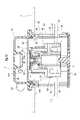
- FIG. 1 It is an exploded perspective view which shows one Embodiment of the full tank control valve which concerns on this invention. It is a perspective view of the same full tank regulation valve. It is sectional drawing in the line of arrow AA of FIG. It is a schematic explanatory drawing when the same full tank regulation valve is attached to a fuel tank. It is a perspective view of the housing body which constitutes the housing in the same full tank regulation valve. It is an exploded perspective view of the float valve which constitutes the same full tank regulation valve. It is a front view of the housing body which constitutes the housing in the same full tank regulation valve.
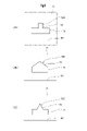
- a modified example of the second flow hole in the same full tank regulation valve is shown, (A) is an enlarged explanatory view showing the first modified example, (B) is an enlarged explanatory view showing the second modified example, and (C) is an enlarged explanatory view. It is an enlarged explanatory view which shows the 3rd modification.
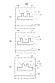
- a modified example of the second flow hole in the same full tank regulation valve is shown, (A) is an enlarged explanatory view showing a fourth modified example, (B) is an enlarged explanatory view showing a fifth modified example, and (C) is an enlarged explanatory view. It is an enlarged explanatory view which shows the 6th modification. It is sectional drawing of the same full tank regulation valve in a state where the full tank regulation is done. FIG.
- FIG. 3 is a cross-sectional view of the full tank regulation valve in a state where the fuel liquid level in the valve chamber is lowered after the full tank regulation shown in FIG. It is sectional drawing of the same full tank regulation valve in the state which additional refueling was performed after the fuel liquid level in the valve chamber as shown in FIG. 11 fell.
- the full tank control valve 10 in this embodiment is attached above the fuel tank 1 as shown in FIGS. 3 and 4.
- a refueling pipe 2 for refueling fuel extends diagonally upward.
- a refueling port 3 is formed at the upper end of the refueling pipe 2.
- a refueling nozzle 4 is inserted into the refueling pipe 2 via a refueling port 3, and fuel is refueled from the refueling nozzle 4 to the inside of the fuel tank 1. It has become like.
- the full tank control valve 10 in this embodiment has a peripheral wall 21 and a partition wall 23, and is a valve that communicates downward into the fuel tank 1 via the partition wall 23.
- a ventilation chamber R communicating with the outside of the fuel tank 1 is provided above the chamber V, and an opening 25 for communicating the valve chamber V and the ventilation chamber R is formed on the partition wall 23, inside the housing 15 and the valve chamber V.
- It has a float valve 40 that is accommodated so as to be able to move up and down, opens and closes the opening 25, and rises when refueling into the fuel tank 1 to close the opening 25.
- fuel means liquid fuel (including fuel droplets), and “fuel vapor” means evaporated fuel.
- fuel liquid level L1 the fuel liquid level in the fuel tank 1
- fuel liquid level L2 the fuel liquid level in the valve chamber V
- the housing 15 in this embodiment has a substantially tubular housing body 20, a lower cap 30 mounted below the housing body 20, and an upper cover 35 mounted above the housing body 20. are doing.
- the housing body 20 has a substantially cylindrical peripheral wall 21, and a partition wall 23 is arranged above the peripheral wall 21.
- a plurality of first locking claws 21a are projected below the peripheral wall 21 at equal intervals in the circumferential direction (here, four).
- a plurality of second locking claws 21b are projected above the peripheral wall 21 at equal intervals in the circumferential direction (here, four).
- a ring mounting groove 27 is formed on the upper inner circumference of the peripheral wall 21, and the disk-shaped partition wall 23 is arranged inside the ring mounting groove 27.
- a seal ring 28 is mounted in the ring mounting groove 27.
- a circular opening 25 is formed in the center of the partition wall 23.
- a plurality of thin-walled plate-shaped guide ribs 29 are formed on the inner circumference of the peripheral wall 21 at a position from the middle of the peripheral wall 21 to the partition wall 23.
- the lower cap 30 has a plurality of through holes 31 formed at the bottom thereof and a plurality of locking holes 32 formed on the outer periphery thereof.
- the upper cover 35 has a substantially hat shape with the upper part closed, and the first connecting pipe 37 and the second connecting pipe 38 extend from a predetermined portion of the peripheral wall 36 in the outer diameter direction.
- the first connecting pipe 37 is connected to the tube 5a connected to the canister 5 arranged outside the fuel tank 1.
- a tube 6a connected to a valve 6 such as a check valve or a cut valve is connected to the second connecting pipe 38.
- the first connecting pipe 37 extends from a fuel vapor discharge port (not shown) provided on the peripheral wall 36, and the second connecting pipe 38 extends from a communication hole 38a (see FIG. 3) provided on the peripheral wall 36.
- a plurality of frame-shaped locking pieces 39 extend from below the peripheral wall 36. Then, by locking each locking piece 39 to each second locking claw 21b of the housing body 20, the seal ring 28 mounted in the ring mounting groove 27 is placed on the inner circumference of the peripheral wall 36 of the upper cover 35. The upper cover 35 is mounted above the housing body 20 in the abutted state (see FIG. 3). As a result, a ventilation chamber R communicating with the outside of the fuel tank 1 is formed above the partition wall 23 (see FIG. 3).
- a float valve 40 that opens and closes the opening 25 is located between the lower cap 30 and the float valve urging spring S (hereinafter, simply “urging spring S”) formed of a coil spring. It is designed to be accommodated and arranged so that it can be raised and lowered with the intervention of).
- the float valve 40 rises due to its own buoyancy and the urging force of the urging spring S when the fuel is immersed, and descends by its own weight when the fuel is not immersed.
- the float valve 40 of this embodiment is mounted on a lower member 41 that generates buoyancy during fuel immersion and above the lower member 41, and is relatively relative to the lower member 41. It has an upper member 45 that moves up and down and is brought into contact with and separated from the opening 25. Further, the float valve 40 has a seal valve body 50 mounted on the upper member 45 and an intermediate valve body 55 arranged between the lower member 41 and the upper member 45.
- the seal valve body 50 is composed of a shaft portion 51 having a protrusion 51a on the outer periphery of the lower end portion and a seal flange 52 extending in an annular shape from the peripheral edge of the upper end portion of the shaft portion 51, and is made of an elastic material such as rubber or an elastic elastomer. It is integrally formed. Further, the shaft portion 51 is formed with a communication hole 53 extending in the axial direction of the float valve 40 and opening upward and downward (see FIG. 3).
- the lower member 41 has a cylindrical lower main body 42, an upper member assembling portion 43 that protrudes from the center of the upper part of the lower main body 42 and has a smaller diameter than the lower main body 42, and an upper portion of the upper member assembling portion 43. It has an intermediate valve body assembly portion 44 that protrudes from the center and has a smaller diameter than the upper member assembly portion 43.
- the intermediate valve body 55 is mounted on the outer periphery of the intermediate valve body assembly portion 44.
- the intermediate valve body 55 has a substantially hat shape in which the upper portion is closed and a plurality of frame-shaped locking frames 56 are provided on the outer periphery thereof.
- the upper center of the intermediate valve body 55 is supported by the support protrusion 44b, and a plurality of locking frames 56 can be locked to the annular protrusion 44a.
- the intermediate valve body 55 is tiltably mounted on the valve body assembly portion 44. Further, the intermediate valve body 55 is always in contact with the lower end portion of the shaft portion 51 of the seal valve body 50 to close the lower opening 53a of the communication hole 53 provided in the coaxial portion 51 (FIG. FIG. 3). As shown in FIG. 11, the lower opening 53a of the communication hole 53 of the shaft portion 51 opens when the lower member 41 descends with respect to the upper member 45.
- the upper member 45 is a ceiling portion 46, a substantially cylindrical peripheral wall 47 extending from the back surface (lower surface) of the ceiling portion 46, and the back surface of the ceiling portion 46, and is inside the peripheral wall 47. It has a plurality of elastic engagement pieces 48 (see FIG. 3) extending from the ceiling.
- the ceiling portion 46 has a substantially disk shape, and a circular support hole 46a is formed in the center thereof. Further, a plurality of holes 46b are formed through the outer periphery of the ceiling portion 46. Further, inside each elastic engaging piece 48, an engaging hole 48a having an elongated hole shape extending with a predetermined length is provided (see FIG. 3).
- the shaft portion 51 is inserted from the front side of the support hole 46a, and the protrusion 51a is locked to the back peripheral edge of the support hole 46a to seal the upper member 45 on the surface (upper surface) side of the ceiling portion 46.
- the valve body 50 is attached. Further, by inserting the protruding engaged portion 43a of the lower member 41 into the engaging hole 48a of each elastic engaging piece 48, the upper member 45 moves up and down by a predetermined distance with respect to the lower member 41. It is designed to be assembled as possible. The upper member 45 can also be tilted with respect to the lower member 41.
- the float valve 40 in this embodiment has a multi-part configuration composed of a lower member 41, an upper member 45, and the like.
- a float valve for example, a float valve having a seal member made of an elastic material mounted above it.
- the shape and structure of the opening 25 are not particularly limited as long as the opening 25 can be opened and closed.
- the peripheral wall 21 of the housing body 20 constituting the housing 15 has a first distribution hole 60 and a first flow hole 60 for communicating the internal space of the fuel tank 1 and the internal space of the valve chamber V.
- Two flow holes 70 and a third flow hole 80 are formed.
- these flow holes 60, 70, 80 will be described with reference to FIGS. 5 and 7.
- the first flow hole 60 extends to the lower side of the peripheral wall 21 of the housing body 20 with a predetermined length L1 along the circumferential direction, and is predetermined in the axial direction of the housing 15 (the same direction as the axial direction of the float valve 40). It has a substantially elongated hole shape elongated in the circumferential direction, formed at a height of H1.
- the first flow hole 60 is arranged at a height that regulates full tank before additional refueling, and allows the internal space of the fuel tank 1 and the internal space of the valve chamber V to communicate with each other in a state where the fuel tank 1 is not submerged. , It is formed with an opening area that enables continuous refueling from the refueling nozzle 4.
- the air inflow speed from the second flow hole 70 and the third flow hole 80 cannot keep up with the continuous refueling speed from the refueling nozzle 4, and the inside of the valve chamber V.
- the fuel liquid level L2 rises, the float valve 40 closes the opening 25, and continuous refueling from the refueling nozzle 4 is stopped (see FIG. 10).
- non-submerged state in the first flow hole means a state in which the fuel tank is opened without being blocked by the liquid fuel and the inside of the fuel tank and the valve chamber are in communication with each other.
- the “submerged state” means a state in which the communication between the inside of the fuel tank and the valve chamber is cut off by being blocked by the liquid fuel.
- a pair of first flow holes 60, 60 are formed at locations facing the peripheral wall 21 in the circumferential direction (see FIG. 3). Further, as shown in FIG. 7, each first flow hole 60 is positioned so that both ends in the circumferential direction are aligned with the first locking claws 21a and 21a protruding from the peripheral wall 21 in the circumferential direction. It is provided in.
- the flow path area of the first flow hole 60 is larger than the flow path area of the second flow hole 70 and the third flow hole 80, and the flow path area of the first flow hole 60 is larger than that of the second flow hole 70 and the third flow hole 80. Is located downward in the axial direction of the housing 15.
- the second flow hole 70 is formed above the peripheral wall 21 of the housing body 20 above the first flow hole 60 and smaller than the first flow hole 60.
- the second distribution hole 70 is arranged at a height that regulates additional refueling, enables additional refueling in a non-submerged state (see FIG. 11), and is configured to stop additional refueling in a submerged state. (See FIG. 12).
- the second flow hole 70 in this embodiment has a substantially elongated hole shape elongated in the circumferential direction, extending along the circumferential direction at a predetermined length L2 and formed at a predetermined height H2 in the axial direction of the housing 15. None. Further, the circumferential length L2 of the second flow hole 70 is shorter than the circumferential length L1 of each first flow hole 60, and the axial height H2 of each second flow hole 70 is. The height of each first flow hole 60 in the axial direction is lower than H1. As a result, the second flow hole 70 is formed smaller than the first flow hole 60.
- a pair of second flow holes 70, 70 are formed at locations facing the peripheral wall 21 in the circumferential direction (see FIG. 3). Further, as shown in FIG. 7, each second flow hole 70 is arranged at the center in the circumferential direction of the long hole-shaped first flow hole 60.
- the flow path area of the second flow hole 70 is smaller than the flow path area of the first flow hole 60 and larger than the flow path area of the third flow hole 80, and the shaft of the housing 15 is provided. It is located between the first flow hole 60 and the third flow hole 80 in the direction.
- the third distribution hole 80 is formed above the peripheral wall 21 of the housing body 20 above the second distribution hole 70 and smaller than the second distribution hole 70.
- the third distribution hole 80 is always maintained in a non-submerged state even when the first flow hole 60 and the second flow hole 0 are submerged by fuel, except when the vehicle rolls over or is turned over. (See FIGS. 3 and 10-12).
- the third flow hole 80 is in the valve chamber V from the fuel liquid level L1 in the fuel tank 1 even when the first flow hole 60 and the second flow hole 70 are in the liquid state without being submerged. If the fuel liquid level L2 is high, the air in the fuel tank 1 is configured to flow into the valve chamber V (see FIG. 10).
- the fuel liquid level L2 in the valve chamber V is the fuel in the fuel tank 1. If it is higher than the liquid level L1, the third flow hole 80 is configured to allow the air in the fuel tank 1 to flow into the valve chamber V.
- the third flow hole 80 in this embodiment has a circular shape, and its inner diameter D is smaller than the circumferential length L2 and the axial height H2 of the second flow hole 70. As a result, the third flow hole 80 is formed smaller than the second flow hole 70.
- a pair of third flow holes 80, 80 are formed at locations facing the peripheral wall 21 in the circumferential direction (see FIG. 3). Further, as shown in FIG. 7, each third flow hole 80 is the center of the circumferential second flow hole 70 in the circumferential direction, and is adjacent to the second flow hole protruding from the peripheral wall 21 in the circumferential direction. It is provided so as to be located between the locking claws 21b and 21b.
- the flow path area of the third flow hole 80 is smaller than the flow path areas of the first flow hole 60 and the second flow hole 70, and the third flow hole 80 is located at the uppermost position in the axial direction of the housing 15. ing.
- the shapes of the first flow hole, the second flow hole, and the third flow hole are, for example, triangular hole shape, square hole shape, polygonal hole shape of pentagon or more, rhombic hole shape, round hole shape, and elliptical shape. It may be in the shape of a hole, a slit hole (a pore thinner than a long hole), etc., and the size of each flow hole, that is, the size relationship of the flow path area of each flow hole (the flow path of the first flow hole).
- the area is not particularly limited as long as the area> the flow path area of the second flow hole> the flow path area of the third flow hole) is maintained.
- the second distribution hole may have the shape shown in FIGS. 8 and 9.
- These second distribution holes 70A, 70B, 70C, 70D, 70E, 70F have a base 71 extending along the circumferential direction of the peripheral wall 21 and an upper end of the base 71 toward the upper side of the peripheral wall 21 from the base 71. It is composed of a notch 73 having a narrow width. The details will be described below.
- the second flow hole 70A shown in FIG. 8A has a base portion 71 extending at a constant height along the circumferential direction of the peripheral wall 21, and an upper end of the base portion 71 from the center in the circumferential direction toward the upper side of the peripheral wall 21. It is composed of a notch portion 73 that is narrower than the base portion 71 and extends with a constant width. The channel area of the notch 73 is smaller than the channel area of the base 71.
- the second flow hole 70B shown in FIG. 8B has a base portion 71 extending at a constant height along the circumferential direction of the peripheral wall 21, and an upper end of the base portion 71 from both ends in the circumferential direction above the peripheral wall 21. It is composed of a notch portion 73 that extends in a tapered shape that gradually narrows toward the direction and has a substantially triangular shape.
- the notch portion 73 has the same circumferential length as the base portion 71 at the lower end side thereof, but the flow path area thereof is smaller than the flow path area of the base portion 71.
- the second flow hole 70C shown in FIG. 8C has a base portion 71 extending at a constant height along the circumferential direction of the peripheral wall 21, and an upper end of the base portion 71, which is above the peripheral wall 21 from the central portion in the circumferential direction. It is composed of a notch portion 73 that extends in a tapered shape that gradually narrows toward the direction and has a substantially triangular shape. The channel area of the notch 73 is smaller than the channel area of the base 71.
- the second flow hole 70D shown in FIG. 9 (A) has a base portion 71 extending at a constant height along the circumferential direction of the peripheral wall 21, and an upper end of the base portion 71, which is above the peripheral wall 21 from two locations in the circumferential direction. It is composed of a pair of notches 73, 73 that are narrower than the base 71 and extend with a constant width toward the base 71. The flow path area of each notch 73 is smaller than the flow path area of the base 71.
- the second flow hole 70E shown in FIG. 9B is a base portion 71 having a recess 71a extending downward along the circumferential direction of the peripheral wall 21 and denting downward in the center of the upper end portion, and the upper end of the base portion 71. It is composed of a pair of notches 73, 73 extending from both side edges in the circumferential direction of the recess 71a toward the upper side of the peripheral wall 21 with a width narrower and a constant width than the base portion 71. The flow path area of each notch 73 is smaller than the flow path area of the base 71 provided with the recess 71a.
- the second flow hole 70F shown in FIG. 9C has a base portion 71 extending along the circumferential direction of the peripheral wall 21 and having a convex portion 71b extending upward in the center of the upper end portion, and a base portion 71 of the base portion 71. It is composed of a pair of notches 73, 73 which are the upper ends of the convex portions 71b and extend from both ends in the circumferential direction toward the upper side of the peripheral wall 21 with a width narrower and a constant width than the base portion 71. The flow path area of each notch 73 is smaller than the flow path area of the base 71.
- the first flow hole side is formed to have a shape consisting of a base portion and a narrow notch portion, or both the first flow hole and the second flow hole are formed of a base portion and a narrow notch portion. It may be shaped.
- the second distribution hole 70 is provided at a position deviated toward the first distribution hole 60, and is slightly separated from the third distribution hole 30, but the first distribution hole 70 is provided.
- the positions of the holes, the second flow hole, and the third flow hole are in the positional relationship of each flow hole (the first flow hole is located at the bottom, the third flow hole is located at the top, and the second flow hole is the first. It is not particularly limited as long as it is located between the 1st flow hole and the 3rd flow hole).
- the second flow hole is formed at a position overlapping the circumferential range of the first flow hole (wrapping position), and the third flow hole overlaps with the circumferential range of the second flow hole (the position where the second flow hole overlaps the circumferential range (wrapping position). It is preferably formed at the wrapping position).
- a set of flow holes 60, 70, 80 are provided on one side of the peripheral wall 21 in the circumferential direction, and a set of flow holes 60, on the other side of the peripheral wall 21 in the circumferential direction.
- 70 and 80 are provided (see FIG. 3), for example, one set of distribution holes 60, 70 and 80 may be provided in three or more sets, and the number and arrangement of each distribution hole is not particularly limited.
- this full tank regulation valve 10 enables quick additional refueling after full tank regulation as follows. The details will be described below.
- the air in the fuel tank 1 passes through the flow holes 60, 70, 80, flows into the valve chamber V, and further passes through the opening 25. Then, it flows into the ventilation chamber R and is discharged to the canister 5 outside the fuel tank 1 via the tube 5a. In this way, the air in the fuel tank 1 is discharged to the outside of the fuel tank 1, so that fuel can be refueled in the fuel tank 1.
- the fuel flows into the valve chamber V through the first distribution hole 60. Then, the lower member 41 is immersed in the fuel that has flowed into the valve chamber V, so that the float valve 40 gradually rises. Until the first flow hole 60 is submerged, the fuel liquid level L1 in the fuel tank 1 and the fuel liquid level L2 in the valve chamber V are at the same height.
- the fuel liquid level L2 rises at once in the valve chamber V, and the second flow hole 70 is also submerged.
- the float valve 40 is further raised, the seal valve body 50 comes into contact with the back peripheral portion of the opening 25, and the opening 25 is closed.
- the air flow between the valve chamber V and the ventilation chamber R through the opening 25 is cut off.
- the fuel in the fuel tank 1 rises in the refueling pipe 2, and the fuel comes into contact with the full tank detection sensor (not shown) of the refueling nozzle 4 inserted into the refueling pipe 2 through the refueling port 3 to fill the tank. Is detected, refueling into the fuel tank 1 is stopped and full tank regulation is performed.
- the third flow hole 80 is open without being submerged (see FIG. 10).
- the fuel liquid level L2 in the valve chamber V is higher than the fuel liquid level L1 in the fuel tank 1
- the third flow hole 80 causes the air in the fuel tank 1 to flow into the valve chamber V. It is configured (see FIG. 10). Therefore, as shown by the arrow F1 in FIG. 10, the air in the fuel tank 1 flows into the valve chamber V from the third flow hole 80. Then, as shown in FIG. 11, the fuel liquid level L2 in the valve chamber V descends, and the amount of fuel immersed in the lower member 41 decreases.
- the fuel liquid level L2 in the valve chamber V descends until the second flow hole 70 does not submerge and opens, the inside of the fuel tank 1 and the inside of the valve chamber V communicate with each other through the second flow hole 70.
- the fuel liquid level L2 in the valve chamber V descends until it becomes the same height as the fuel liquid level L1 in the fuel tank 1.
- the intermediate valve body 55 separates from the seal valve body 50, and the lower opening 53a of the communication hole 53 of the seal valve body 50 opens (see FIG. 11). ..
- the opening 25 communicates with the valve chamber V and the ventilation chamber R through the communication hole 53 of the seal valve body 50.
- the first flow hole 60 is maintained in a submerged state (the closed state is maintained), but the second flow hole 70 and the opening 25 are opened without being submerged. Therefore, as shown by the arrow F2 in FIG. 11, the air in the fuel tank 1 can be discharged to the outside of the fuel tank 1 through the second flow hole 70 and the opening 25 (here, the air is discharged).
- FIG. 12 additional refueling into the fuel tank 1 becomes possible until the second flow hole 70 is closed.
- the air in the fuel tank 1 flows into the valve chamber V from the third flow hole 80 in which the state of not being submerged is maintained, and the air in the valve chamber V flows into the valve chamber V.
- the lower member 41 descends with respect to the upper member 45 to which the abutting seal valve body 50 attached to the back peripheral edge portion of the opening 25 is attached.
- the first flow hole 60 and the second flow hole 70 are set in a state of not being submerged in the peripheral wall 21 of the housing 15 even if the first flow hole 60 and the second flow hole 70 are submerged, and air flows into the valve chamber V. Since the third flow hole 80 is provided so that the air can easily flow into the valve chamber V from the third flow hole 80 after the full tank regulation shown in FIG. 10 (see arrow F1 in FIG. 10). ), The descending speed of the fuel liquid level L2 in the valve chamber V after the full tank regulation can be increased, and additional refueling can be quickly performed after the full tank regulation.
- the float valve 40 is mounted on the lower member 41 and above the lower member 41, moves up and down relative to the lower member 41, and is brought into contact with and separated from the opening 25.
- the upper member 45 is formed with a communication hole 53 extending in the axial direction of the float valve 40 and opening upward and downward, and the lower member 41 is formed in the communication hole 53.
- the lower opening 53a is configured to open when descending with respect to the member 45.
- the lower opening 53a of the communication hole 53 formed in the upper member 45 opens (see FIG. 11), so that the upper member 45 hits the opening 25. Even if they are in contact with each other, it is possible to enable air flow between the valve chamber V and the ventilation chamber R, and it is possible to secure a flow passage for the air flowing into the valve chamber V from the third flow hole 80. As a result, the amount of airflow of the gas flowing into the valve chamber V from the third flow hole 80 can be increased (air flows smoothly because the air flow passage is secured), and the fuel in the valve chamber V can be increased.
- the descending speed of the liquid level L2 can be further increased to facilitate the opening of the second flow hole 70, and additional refueling after the full tank regulation can be performed more quickly.
- the second flow holes 70A, 70B, 70C, 70D, 70E, 70F have a base 71 extending along the circumferential direction of the peripheral wall 21 and a peripheral wall 21 from the upper end of the base 71.
- it is composed of a notch 73 having a width narrower than that of the base 71 toward the upper side of the above, the following effects are obtained.
- the base 71 is first liquid at the time of refueling the fuel tank 1 or at the time of additional refueling.
- the notch 73 having a narrower width is submerged, so that the second flow hole can be suppressed from submerging at once, and the fuel blowout from the fuel filler port 3 can be suppressed.
- the first flow hole is composed of a base and a narrow notch, and both the first flow hole and the second flow hole are composed of a base and a narrow notch. In the same case, the same effect can be obtained.
- the present invention is not limited to the above-described embodiments, and various modified embodiments are possible within the scope of the gist of the present invention, and such embodiments are also included in the scope of the present invention. ..
Landscapes
- Engineering & Computer Science (AREA)
- Life Sciences & Earth Sciences (AREA)
- Sustainable Development (AREA)
- Sustainable Energy (AREA)
- Chemical & Material Sciences (AREA)
- Combustion & Propulsion (AREA)
- Transportation (AREA)
- Mechanical Engineering (AREA)
- Cooling, Air Intake And Gas Exhaust, And Fuel Tank Arrangements In Propulsion Units (AREA)
- Float Valves (AREA)
- Self-Closing Valves And Venting Or Aerating Valves (AREA)
Priority Applications (1)
| Application Number | Priority Date | Filing Date | Title |
|---|---|---|---|
| JP2022556961A JP7422246B2 (ja) | 2020-10-15 | 2021-10-11 | 満タン規制バルブ |
Applications Claiming Priority (2)
| Application Number | Priority Date | Filing Date | Title |
|---|---|---|---|
| JP2020-174207 | 2020-10-15 | ||
| JP2020174207 | 2020-10-15 |
Publications (1)
| Publication Number | Publication Date |
|---|---|
| WO2022080302A1 true WO2022080302A1 (ja) | 2022-04-21 |
Family
ID=81208187
Family Applications (1)
| Application Number | Title | Priority Date | Filing Date |
|---|---|---|---|
| PCT/JP2021/037537 Ceased WO2022080302A1 (ja) | 2020-10-15 | 2021-10-11 | 満タン規制バルブ |
Country Status (2)
| Country | Link |
|---|---|
| JP (1) | JP7422246B2 (https=) |
| WO (1) | WO2022080302A1 (https=) |
Citations (4)
| Publication number | Priority date | Publication date | Assignee | Title |
|---|---|---|---|---|
| JPH08105571A (ja) * | 1994-10-06 | 1996-04-23 | Toyota Motor Corp | 燃料タンクの制御弁 |
| JP2004042899A (ja) * | 2002-07-05 | 2004-02-12 | Toyoda Gosei Co Ltd | 燃料タンクの燃料流出規制装置 |
| JP2005138677A (ja) * | 2003-11-05 | 2005-06-02 | Toyoda Gosei Co Ltd | 満タン検知バルブ |
| JP2019183707A (ja) * | 2018-04-05 | 2019-10-24 | 株式会社パイオラックス | 弁装置 |
-
2021
- 2021-10-11 WO PCT/JP2021/037537 patent/WO2022080302A1/ja not_active Ceased
- 2021-10-11 JP JP2022556961A patent/JP7422246B2/ja active Active
Patent Citations (4)
| Publication number | Priority date | Publication date | Assignee | Title |
|---|---|---|---|---|
| JPH08105571A (ja) * | 1994-10-06 | 1996-04-23 | Toyota Motor Corp | 燃料タンクの制御弁 |
| JP2004042899A (ja) * | 2002-07-05 | 2004-02-12 | Toyoda Gosei Co Ltd | 燃料タンクの燃料流出規制装置 |
| JP2005138677A (ja) * | 2003-11-05 | 2005-06-02 | Toyoda Gosei Co Ltd | 満タン検知バルブ |
| JP2019183707A (ja) * | 2018-04-05 | 2019-10-24 | 株式会社パイオラックス | 弁装置 |
Also Published As
| Publication number | Publication date |
|---|---|
| JP7422246B2 (ja) | 2024-01-25 |
| JPWO2022080302A1 (https=) | 2022-04-21 |
Similar Documents
| Publication | Publication Date | Title |
|---|---|---|
| US8720472B2 (en) | Fuel cutoff valve | |
| US8720471B2 (en) | Fuel cutoff valves | |
| JP6295905B2 (ja) | 燃料遮断弁 | |
| JP2006097674A (ja) | 燃料遮断弁 | |
| US20240255065A1 (en) | Valve device for fuel tank | |
| JP2010143498A (ja) | 燃料遮断弁 | |
| US12134314B2 (en) | Fill-up restriction valve | |
| JP5949686B2 (ja) | インタンク用弁ユニット | |
| JP7441339B2 (ja) | 満タン規制バルブ | |
| US12172515B2 (en) | Valve device | |
| WO2022080302A1 (ja) | 満タン規制バルブ | |
| JP2011235772A (ja) | 燃料遮断弁 | |
| JP7442698B2 (ja) | 弁装置 | |
| JP2004353518A (ja) | 満タン規制バルブ | |
| JP5461087B2 (ja) | 燃料遮断弁 | |
| JP6705055B2 (ja) | 燃料タンク用弁装置 | |
| US12090838B2 (en) | Valve device for fuel tank | |
| JP2017106525A (ja) | 燃料タンク用弁装置 | |
| WO2022215586A1 (ja) | ピラー付き弁装置 | |
| JP6070453B2 (ja) | 燃料遮断装置 | |
| JP4881660B2 (ja) | 液体遮断弁装置 | |
| WO2022158489A1 (ja) | 弁装置 | |
| US20060162777A1 (en) | Fuel-effusion prevention valve | |
| US12427856B2 (en) | Valve device for fuel tank | |
| WO2012118118A1 (ja) | 燃料遮断弁 |
Legal Events
| Date | Code | Title | Description |
|---|---|---|---|
| 121 | Ep: the epo has been informed by wipo that ep was designated in this application |
Ref document number: 21880041 Country of ref document: EP Kind code of ref document: A1 |
|
| DPE1 | Request for preliminary examination filed after expiration of 19th month from priority date (pct application filed from 20040101) | ||
| ENP | Entry into the national phase |
Ref document number: 2022556961 Country of ref document: JP Kind code of ref document: A |
|
| NENP | Non-entry into the national phase |
Ref country code: DE |
|
| 122 | Ep: pct application non-entry in european phase |
Ref document number: 21880041 Country of ref document: EP Kind code of ref document: A1 |