WO2022158489A1 - 弁装置 - Google Patents
弁装置 Download PDFInfo
- Publication number
- WO2022158489A1 WO2022158489A1 PCT/JP2022/001789 JP2022001789W WO2022158489A1 WO 2022158489 A1 WO2022158489 A1 WO 2022158489A1 JP 2022001789 W JP2022001789 W JP 2022001789W WO 2022158489 A1 WO2022158489 A1 WO 2022158489A1
- Authority
- WO
- WIPO (PCT)
- Prior art keywords
- valve
- discharge port
- valve body
- chamber
- partition wall
- Prior art date
Links
- 239000000446 fuel Substances 0.000 claims abstract description 61
- 238000005192 partition Methods 0.000 claims abstract description 45
- 238000009423 ventilation Methods 0.000 claims abstract description 34
- 239000002828 fuel tank Substances 0.000 claims abstract description 32
- 239000012530 fluid Substances 0.000 claims abstract description 12
- 230000000903 blocking effect Effects 0.000 abstract 1
- 230000002093 peripheral effect Effects 0.000 description 28
- 210000000078 claw Anatomy 0.000 description 5
- 239000003502 gasoline Substances 0.000 description 3
- 230000000694 effects Effects 0.000 description 2
- 229920001971 elastomer Polymers 0.000 description 2
- 230000002265 prevention Effects 0.000 description 2
- 238000000926 separation method Methods 0.000 description 2
- 230000001174 ascending effect Effects 0.000 description 1
- 230000003247 decreasing effect Effects 0.000 description 1
- 239000013013 elastic material Substances 0.000 description 1
- 239000000806 elastomer Substances 0.000 description 1
- 239000007788 liquid Substances 0.000 description 1
- 239000002184 metal Substances 0.000 description 1
- 229910001220 stainless steel Inorganic materials 0.000 description 1
- 239000010935 stainless steel Substances 0.000 description 1
- 238000003466 welding Methods 0.000 description 1
Images


Classifications
-
- B—PERFORMING OPERATIONS; TRANSPORTING
- B60—VEHICLES IN GENERAL
- B60K—ARRANGEMENT OR MOUNTING OF PROPULSION UNITS OR OF TRANSMISSIONS IN VEHICLES; ARRANGEMENT OR MOUNTING OF PLURAL DIVERSE PRIME-MOVERS IN VEHICLES; AUXILIARY DRIVES FOR VEHICLES; INSTRUMENTATION OR DASHBOARDS FOR VEHICLES; ARRANGEMENTS IN CONNECTION WITH COOLING, AIR INTAKE, GAS EXHAUST OR FUEL SUPPLY OF PROPULSION UNITS IN VEHICLES
- B60K15/00—Arrangement in connection with fuel supply of combustion engines or other fuel consuming energy converters, e.g. fuel cells; Mounting or construction of fuel tanks
- B60K15/03—Fuel tanks
- B60K15/035—Fuel tanks characterised by venting means
-
- F—MECHANICAL ENGINEERING; LIGHTING; HEATING; WEAPONS; BLASTING
- F02—COMBUSTION ENGINES; HOT-GAS OR COMBUSTION-PRODUCT ENGINE PLANTS
- F02M—SUPPLYING COMBUSTION ENGINES IN GENERAL WITH COMBUSTIBLE MIXTURES OR CONSTITUENTS THEREOF
- F02M25/00—Engine-pertinent apparatus for adding non-fuel substances or small quantities of secondary fuel to combustion-air, main fuel or fuel-air mixture
- F02M25/08—Engine-pertinent apparatus for adding non-fuel substances or small quantities of secondary fuel to combustion-air, main fuel or fuel-air mixture adding fuel vapours drawn from engine fuel reservoir
-
- F—MECHANICAL ENGINEERING; LIGHTING; HEATING; WEAPONS; BLASTING
- F02—COMBUSTION ENGINES; HOT-GAS OR COMBUSTION-PRODUCT ENGINE PLANTS
- F02M—SUPPLYING COMBUSTION ENGINES IN GENERAL WITH COMBUSTIBLE MIXTURES OR CONSTITUENTS THEREOF
- F02M37/00—Apparatus or systems for feeding liquid fuel from storage containers to carburettors or fuel-injection apparatus; Arrangements for purifying liquid fuel specially adapted for, or arranged on, internal-combustion engines
-
- F—MECHANICAL ENGINEERING; LIGHTING; HEATING; WEAPONS; BLASTING
- F16—ENGINEERING ELEMENTS AND UNITS; GENERAL MEASURES FOR PRODUCING AND MAINTAINING EFFECTIVE FUNCTIONING OF MACHINES OR INSTALLATIONS; THERMAL INSULATION IN GENERAL
- F16K—VALVES; TAPS; COCKS; ACTUATING-FLOATS; DEVICES FOR VENTING OR AERATING
- F16K24/00—Devices, e.g. valves, for venting or aerating enclosures
- F16K24/04—Devices, e.g. valves, for venting or aerating enclosures for venting only
Definitions
- the present invention relates to a valve device attached to a fuel tank of an automobile or the like and used as a fuel outflow prevention valve, a full-tank regulation valve, or the like.
- the fuel tank of a vehicle is equipped with a valve device that prevents the fuel in the fuel tank from leaking out of the fuel tank when the vehicle tilts or rolls over.
- a valve device generally has a housing with a vent chamber at the top and a valve chamber at the bottom via a partition wall having a vent hole, and a float valve arranged in the valve chamber so as to move up and down. .
- a valve case is partitioned into a gas collection chamber and a vent chamber by a partition wall, a communication port is formed in the partition wall for communicating the gas collection chamber and the ventilation chamber, and a communication port is formed on the partition wall.
- a cylindrical guide wall is erected so as to surround the peripheral edge of the port, and the guide wall is formed with a discharge port for communicating with the outside of the valve case.
- a valve device is described in which a valve body is detachable and seatable. Further, when the valve body separates from the communicating port peripheral portion and comes into contact with the valve case, the valve body seating surface is inclined with respect to the communicating port peripheral portion, and the seating surface of the valve body is inclined relative to the communicating port peripheral portion. The side farthest from the peripheral portion is set to be positioned on the outlet side.
- a float valve is arranged in the gas collecting chamber so as to be movable up and down.
- an object of the present invention is to provide a valve device that makes it difficult for the float valve to float up and makes it easy to lower the pressure in the fuel tank.
- a valve device is provided with a valve chamber downwardly communicating with the inside of a fuel tank and a vent chamber upwardly communicating with the outside of the fuel tank through a partition wall.
- a housing having a vent hole communicating between the valve chamber and the vent chamber; a float valve housed in the valve chamber so as to be movable up and down and opening and closing the vent hole;
- a fuel vapor discharge port is formed in the housing above the partition wall and communicates with the ventilation chamber, and the fuel vapor discharge port communicates with the fuel vapor discharge port.
- a fuel vapor discharge pipe connected to a canister arranged outside the tank is provided, and the valve body is configured so that the flow rate per unit time of the fluid flowing into the ventilation chamber through the ventilation hole exceeds a predetermined value. It is characterized in that it is configured to be pushed up at times to partially block the fuel vapor discharge port.
- the valve body when the pressure in the fuel tank rises and the fluid such as fuel vapor passes through the vent hole and flows into the vent chamber, and the flow rate per unit time exceeds a predetermined value, the valve body is pushed up and partially blocks the fuel vapor outlet, so that the passage area of the fuel vapor outlet is reduced. As a result, the flow resistance of the fluid flowing through the fuel vapor discharge port increases, making it difficult for the fluid to flow within the housing. It can be lowered easily.
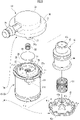
- FIG. 1 is an exploded perspective view showing one embodiment of a valve device according to the present invention
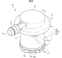
- FIG. It is a perspective view of the same valve apparatus.
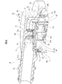
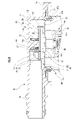
- FIG. 3 is a cross-sectional view taken along the line AA of FIG. 2;
- FIG. 2 is a perspective view of an upper cover that constitutes the same valve device, viewed from a direction different from that of FIG. 1; It is a top view of the same top cover.
- FIG. 4 is an enlarged cross-sectional perspective view of a main portion of the valve device according to the present invention, showing a state in which the valve body is lowered; 7 is an enlarged explanatory view of the state of FIG. 6;
- FIG. FIG. 4 is an enlarged explanatory view of a main part of the valve device according to the present invention in a state where the valve body is lifted;
- valve device An embodiment of a valve device according to the present invention will be described below with reference to the drawings.
- the valve device 10 of this embodiment has a valve chamber V downwardly communicating with the inside of the fuel tank and an upwardly communicating vent chamber R communicating with the outside of the fuel tank.
- a housing 15 having a partition wall 23 formed with a ventilation hole 25 communicating the valve chamber V and the ventilation chamber R; , and a valve body 80 arranged in the ventilation chamber R so as to be movable up and down.
- the housing 15 of this embodiment also has a housing body 20 , a lower cap 40 attached below the housing body 20 , and an upper cover 50 attached above the housing body 20 .
- fuel means liquid fuel (including fuel droplets)
- fuel vapor means vaporized fuel (gaseous fuel).
- the housing body 20 will be described with reference to FIGS. 1 and 4-6.
- the housing body 20 has a substantially cylindrical peripheral wall 21, above which the partition wall 23 is arranged.
- a circular ventilation hole 25 is formed in the center of the partition wall 23 to allow the valve chamber V and the ventilation chamber R to communicate with each other.
- a substantially cross-shaped rib 25a is provided inside the vent hole 25. As shown in FIG.
- a plurality of first locking claws 21a protrude at even intervals in the circumferential direction.
- a plurality of second locking claws 21b protrude above the peripheral wall 21 at equal intervals in the circumferential direction.
- a flange portion 27 protrudes from the upper outer periphery of the peripheral wall 21 .
- a ring mounting groove 27a is formed inside the flange portion 27, and an annular seal ring 27b is mounted in the ring mounting groove 27a (see FIG. 3).
- a plurality of protrusions 29 are provided on the upper surface side of the partition wall 23 and outside the ventilation holes 25 at equal intervals in the circumferential direction. These protrusions 29 support the valve body 80 in a floating state from the upper surface of the partition wall 23 (see FIG. 3) so that the vent hole 25 is not completely blocked even when the valve body 80 is lowered. do.
- a substantially cylindrical guide wall 31 is provided with a separation portion 31a at a part in the circumferential direction. is established.
- the guide wall 31 has the valve body 80 disposed therein, guides the upward/downward movement of the valve body 80, and regulates the position in the radial direction.
- the lower cap 40 has a bottom wall 41 and a peripheral wall 43 erected from the peripheral edge of the bottom wall 41 .
- the bottom wall 41 is formed with a plurality of through holes 41a.
- a plurality of locking holes 43a are formed in the peripheral wall 43 at equal intervals in the circumferential direction. Then, the peripheral wall 43 of the lower cap 40 is put on the outer periphery of the lower end of the peripheral wall 21 of the housing body 20, and the first locking claws 21a corresponding to the locking holes 43a are engaged with each other.
- a lower cap 40 is attached below (see FIG. 2).
- a valve chamber V communicating with the inside of the fuel tank (not shown) is formed below the housing through the partition wall 23 (see FIG. 3).
- a float valve 45 for opening and closing the vent hole 25 is arranged between the lower cap 40 and a float valve biasing spring S1 (hereinafter simply referred to as "biasing spring S1") made of a coil spring. ) is interposed, and is housed and arranged so as to be able to move up and down.
- biasing spring S1 float valve biasing spring S1
- the float valve 45 rises by its own buoyancy and the biasing force of the biasing spring S1 when immersed in fuel, and descends by its own weight when not immersed in fuel.
- the float valve 45 includes a float body 46 having a circular outer periphery that generates buoyancy when immersed in fuel, and a seal member 47 that is mounted above the float body 46 and moves up and down relative to the float body 46. and A seal valve element 47a made of an elastic material such as rubber or elastic elastomer is mounted above the seal member 47. As shown in FIG. The seal valve body 47a contacts and separates from the periphery of the lower opening of the ventilation hole 25 to open and close the ventilation hole 25. As shown in FIG. Further, an intermediate valve body 48 is tiltably supported between the float body 46 and the seal member 47 (see FIG. 3). The float valve 45 contacts and separates from the periphery of the lower opening of the ventilation hole 25 by its up-and-down movement to open and close the ventilation hole 25, thereby functioning as a fuel outflow prevention valve and a full tank regulation valve.
- the upper cover 50 constituting the housing 15 includes a peripheral wall 51 having a substantially circular outer periphery and a ceiling wall 53 disposed above the peripheral wall 51 and facing the partition wall 23 . , and a flange portion 55 extending outward from the lower side of the peripheral wall 51, forming a substantially hat shape.
- a plurality of locking pieces 57 extend from the lower end of the peripheral wall 51 at equal intervals in the circumferential direction.
- Each locking piece 57 is formed with a locking hole 57a with which the second locking claw 21b provided on the housing body 20 is locked.
- the housing 15 is formed with a fuel vapor discharge port 70 (hereinafter simply referred to as “discharge port 70") communicating with the ventilation chamber R above the partition wall 23.
- a fuel vapor discharge pipe 75 (hereinafter also simply referred to as “discharge pipe 75”) is provided which communicates with the discharge port 70 and is connected to a not-shown canister disposed outside the fuel tank.
- the housing 15 is provided with a projecting portion 60 projecting in a tubular shape toward the inside of the ventilation chamber R and communicating with the discharge pipe 75 , and the projecting portion 60 has a discharge port 70 formed on the outer periphery thereof. .
- the upper cover 50 that constitutes the housing 15 is provided with a discharge port 70 and a discharge pipe 75 .
- the protruding portion 60 is a predetermined portion in the circumferential direction of the peripheral wall 51 of the upper cover 50 and protrudes in a tubular shape from the inner peripheral surface toward the radial center of the upper cover 50 (the radial center of the ceiling wall 53). It is composed of a first projecting portion 61 and a second projecting portion 63 which is connected to the end of the projecting direction of the first projecting portion 61 and has a frame-like shape with an opening mainly downward (in the direction facing the partition wall 23). ing.
- the first projecting portion 61 has a ceiling portion 61a connected to the ceiling wall 53 of the upper cover 50 and a bottom portion 61b opposite to the ceiling portion 61a, which are parallel to each other.
- the portions 61c, 61c are in the shape of a deformed tube with circular arcs.
- a first discharge port 71 communicating with a discharge pipe 75 is formed at the tip of the first projecting portion 61 in the projecting direction.
- the second projecting portion 63 includes a pair of projecting walls 64, 64 projecting from both ends of the projecting direction of the first projecting portion 61, and a pair of projecting walls 64, 64 extending from the projecting ends of the projecting walls 64, 64. a pair of side walls 65, 65 extending perpendicularly and parallel to each other;
- a connection wall 66 is arranged at a predetermined distance from the first discharge port 71 of 61, and has a substantially square frame shape with an open bottom. The upper ends of the walls 64 , 65 , 66 are connected to the ceiling wall 53 of the upper cover 50 . Moreover, as shown in FIG.
- the protrusion amount of the side wall 65 and the connection wall 66 from the inner surface of the ceiling wall 53 is the same. Furthermore, as shown in FIG. 4, the side wall 65 and the connecting wall 66 protrude so as to be one step lower than the overhang wall 64 .
- the spaces surrounded by the walls 64 , 65 , 66 communicate with the first discharge port 71 of the first projecting portion 61 .
- a lower opening of the second protrusion 63 forms a second discharge port 72 and communicates with the space surrounded by the plurality of walls 64 , 65 , 66 .
- Each side wall 65 is also formed with a notched third discharge port 73 that communicates with the space surrounded by the walls 64 , 65 , 66 .
- the third discharge port 73 has an inner surface 73a on the side of the connecting wall 66 that forms a vertical surface, and an inner surface 73b on the side of the overhang wall 64 that gradually widens with respect to the inner surface 73a from the ceiling wall 53 side toward the lower end. It has a tapered surface that is inclined so that
- each side wall 65 (the end facing the partition wall 23) on the inner surface 73a side and the end face of the lower end of the connecting wall 66 (the end facing the partition wall 23) are stepless.
- a continuous flat valve contact surface 67 is formed (see FIG. 4), and a valve disc 80 contacts this valve contact surface 67 when the valve is raised (see FIG. 4). 8).
- This valve contact surface 67 forms the "end surface facing the partition wall" of the projecting portion in the present invention.
- An end surface 67a (see FIG. 4) of each side wall 65 on the side of the inner surface 73b, which is the lower end portion, does not come into contact with the valve body 80 even if it rises.
- a first discharge port 71 formed in the first projecting portion 61, a second discharge port 72 formed in the second projecting portion 63, and a second discharge port 72 formed in the side wall 65 of the second projecting portion 63 are provided.
- 3 discharge port 73 constitutes the "fuel vapor discharge port” in the present invention.
- the "fuel vapor discharge port” in the present invention means an opening communicating with the internal space of the fuel vapor discharge pipe and communicating with the inside of the ventilation chamber.
- the second discharge port 72 constituting the discharge port 70 constitutes "a portion opened toward the partition wall” in the present invention.
- the projecting portion 60 having the structure described above is formed as shown in FIG. enters the inside of the guide wall 31, the first protrusion 61 is arranged outside the guide wall 31 at a position aligned with the separation portion 31a, and the first protrusion formed in the first protrusion 61 An outlet 71 is arranged so as to face the separating portion 31a.
- the projecting portion 60 including the first projecting portion 61 and the second projecting portion 63 is provided.
- the fuel vapor outlet 70 consisting of 72 and the third outlet 73 is provided, the fuel vapor outlet is not limited to this aspect.
- a fuel vapor discharge port may be provided at a predetermined location on the peripheral wall 51 of the upper cover 50, or (2) a fuel vapor discharge port may be provided at the tip of a tubular projecting portion projecting from the peripheral wall 51 in the projecting direction (this (3) A fuel vapor discharge port is provided at a predetermined location on the ceiling wall 53 or at the tip of the tubular projection extending from the ceiling wall 53 in the projecting direction.
- the overall shape of the protrusion may be, for example, a shape that extends in a simple straight tube shape, or the second protrusion that constitutes the protrusion may be a circular, oval, or oval frame shape, An opening may be provided only in the side wall without providing a lower opening in the second protrusion, and the shape and structure of the protrusion are not particularly limited.
- the opening angle of the first discharge port 71 constituting the fuel vapor discharge port 70 in this embodiment (meaning the angle of the surface surrounded by the opening; the same applies to the following description) is vertical (the vertical direction of the valve body ), and the opening angle of the second discharge port 72 is horizontal (perpendicular to the vertical direction of the valve body), but the opening angle of the fuel vapor discharge port is You may incline at a predetermined angle with respect to the raising/lowering direction of a valve body.
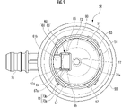
- the discharge pipe 75 extends radially outward from a position aligned with the first projecting portion 61 on the outer surface side of the peripheral wall 51 of the upper cover 50 . As shown in FIG. 5 , when the housing 15 is viewed from the axial direction, the discharge pipe 75 extends on the same straight line as the first projecting portion 61 .
- a tube (not shown) connected to a canister arranged outside the fuel tank is connected to the discharge pipe 75 .
- a substantially cylindrical projection 77 protrudes toward the partition wall 23 from the radial center of the ceiling wall 53 of the upper cover 50 and from the inner surface side thereof.
- the protrusion 77 protrudes perpendicularly to the planar direction of the ceiling wall 53 .
- a lower end surface 77a which is the leading end of the protrusion 77 in the projecting direction, has a flat shape.
- the protrusion amount of the projection 77 from the inner surface of the ceiling wall 53 is the same as the protrusion amount of the side wall 65 and the connecting wall 66 .
- the valve element 80 arranged in the ventilation chamber R so as to be able to move up and down is in the form of a disc with a constant thickness and made of metal such as stainless steel in the case of this embodiment. .
- the outer diameter of the valve body 80 is set to be larger than the outer dimension of the second projecting portion 63 forming the projecting portion 60.
- the valve body 80 is disposed inside the guide wall 31 in the ventilation chamber R and above the ventilation hole 25 formed in the partition wall 23 so as to be able to move up and down.
- a plurality of projections 29 provided on the upper surface of the wall 23 support the partition wall 23 in a floating state.
- the valve element 80 is arranged inside the guide wall 31 so that its movement in the radial direction is restricted so that the upper opening of the vent hole 25 formed in the partition wall 23 is always covered.
- a valve body biasing spring S2 (hereinafter also simply referred to as “biasing spring S2") made of a coil spring is interposed around the outer periphery of the projection 77, and this biasing spring S2 causes the valve body to 80 is biased toward the partition wall 23 side. That is, the valve body 80 is normally biased toward the partition wall 23 by the biasing means (here, the valve body biasing spring S2). However, the valve body 80 may be lowered only by its own weight without providing the valve body biasing spring S2. In this case, the weight of the valve body 80 serves as the urging means.
- the valve body 80 is pushed up to partially block the fuel vapor discharge port 70 when the flow rate per unit time of the fluid flowing into the ventilation chamber R through the ventilation hole 25 exceeds a predetermined value.
- valve body 80 when fuel is supplied to a fuel tank (not shown) and the pressure in the fuel tank rises, as shown in FIGS. After flowing into the chamber V, it passes through the vent hole 25 and comes into contact with the lower surface of the valve body 80 .
- the valve body 80 When the flow rate of the fluid per unit time exceeds a predetermined value set by the biasing force of the biasing spring S2 and the self-weight of the valve body 80, the valve body 80 is pushed up, and the discharge port 70 is partially closed. is blocked (see FIG. 8).
- the valve body 80 is preferably pushed up when, for example, the flow rate of the fluid per unit time exceeds 200 L/min.
- the valve body 80 abuts on the valve body contact surface 67 provided on the projecting portion 60 and the lower end surface 77a of the projection 77, respectively, and the valve body 80 extends beyond that.
- the first discharge port 71 is partially blocked by the thickness of the valve body 80 (the lower opening portion of the first discharge port 71 is blocked).
- the second discharge port 72 is partially blocked by the valve body 80 which is larger than the second projecting portion 63. (The second discharge port 72 is closed except for the portion near the first projecting portion 61.)
- (3) As shown in FIG. is partially blocked by the valve body 80 . In this way, the discharge port 70 is partially blocked by the valve body 80 .
- the shape and structure of the housing body, lower cap, and upper cover that constitute the housing described above are not particularly limited. Further, the housing does not have to be composed of three parts, ie, the housing main body, the lower cap, and the upper cover. Furthermore, the float valve 45 in this embodiment has a multi-part structure consisting of a float body 46, a seal member 47, and the like. etc., and the shape and structure are not particularly limited as long as the air vent 25 can be opened and closed.
- the valve body 80 partially closes all of the discharge ports 71, 72, and 73 that constitute the discharge port 70, but the valve body partially closes the fuel vapor discharge port.
- the covering configuration is not limited to this aspect.
- the valve body is formed in the shape of a square plate that is larger than the second projecting portion, and when the valve body rises, it blocks the entire range of the second discharge port 72 and partially blocks the first discharge port 71.
- the plate thickness of the valve body may be increased or decreased to adjust the amount of partial blockage of the first discharge port, or the position of the valve body may be shifted in the radial direction with respect to the second discharge port. , the amount of partial blockage of the second discharge port and the third discharge port may be adjusted.
- valve element 80 in this embodiment has a disk shape, it may have a polygonal shape, an elliptical shape, an oval shape, or the like, or may have a through-hole, or may have a fuel vapor shape. Any shape may be used as long as it can partially block the discharge port 70 .
- This valve device 10 is mainly installed in the fuel tank of a so-called hybrid car (any type of hybrid car, such as a series system, a parallel system, or a split system) having a gasoline engine and an electric motor.
- the valve device 10 of the present invention may of course be attached to the fuel tank of a vehicle that employs only a normal gasoline engine instead of a hybrid vehicle.
- the valve body 80 is urged by its own weight and the urging spring S2 to descend, and is supported by the plurality of projections 29 in a floating state from the upper surface of the partition wall 23. , and the upper opening of the ventilation hole 25 is also open. Therefore, the valve chamber V and the vent chamber R communicate with each other through the vent hole 25 .
- the first discharge port 71 is partially blocked by the thickness of the valve body 80 (see FIG. 8), and the second discharge port 72 and the third discharge port 73 are partially blocked by the valve body 80. is blocked (see FIG. 5), and the discharge port 70 is partially blocked by the valve body 80 .
- the flow path area of the discharge port 70 is narrowed, so that the flow resistance of the fluid F flowing through the discharge port 70 increases, making it difficult for the fluid F to flow within the housing 15 .
- the float valve 45 can be made less likely to float, making it easier to lower the pressure in the fuel tank.
- the housing 15 is provided with a projecting portion 60 projecting inwardly of the ventilation chamber R in a tubular shape and communicating with the discharge pipe 75.
- a discharge port 70 is formed on the outer periphery of the projecting portion 60 .
- the degree of freedom in forming the discharge port 70 can be increased, so that the discharge port 70 can be formed into a shape that is easy to partially block with the valve body 80 . If the protruding portion 60 is not provided, for example, it is necessary to provide the discharge port 70 in the peripheral wall 51 of the upper cover 50 or the like, which tends to make it difficult to partially block the discharge port 70 with the valve body 80 .
- the outlet 70 has a portion that opens toward the partition wall 23 (here, as shown in FIG. 7, the second outlet 72 opens toward the partition wall 23). is doing).
- the protruding portion 60 has an end surface (here, the valve body contact surface 67) facing the partition wall 23, and the valve body 80 is plate-shaped and protrudes when ascending. It is configured to contact the end surface of the portion 60 (see FIG. 8).
- valve body 80 when the valve body 80 is raised, the valve body 80 can be brought into contact with the projecting portion 60 in a stable posture, so that the flow passage area of the discharge port 70 can be narrowed more stably. can.
- the housing 15 has a ceiling wall 53 that faces the partition wall 23.
- a projection 77 protrudes from the ceiling wall 53 toward the partition wall 23, and the valve body 80 is When it rises and comes into contact with the end surface (valve contact surface 67) of the projecting portion 60, it also comes into contact with the lower end surface 77a of the protrusion 77 (see FIG. 8).
- valve body 80 when the valve body 80 is raised, the valve body 80 can be brought into contact with the protrusion 60 in a more stable posture by the two points of the end surface of the protrusion 60 and the lower end surface 77a of the protrusion 77. can.
- Fuel tank valve device (valve device) 15 Housing 20 Housing body 23 Partition wall 25 Vent 40 Lower cap 45 Float valve 50 Upper cover 51 Peripheral wall 53 Ceiling wall 60 Projection 67 Valve body contact surface (end surface) 70 fuel vapor outlet (outlet) 75 fuel vapor exhaust pipe (exhaust pipe) 77 Protrusion 80 Valve disc V Valve chamber R Vent chamber
Abstract
フロート弁を浮き上がりにくくして、燃料タンク内の圧力を下降させやすい、弁装置を提供する。この弁装置10は、仕切壁23を介して弁室V及び通気室Rが設けられたハウジング15と、通気孔25を開閉するフロート弁45と、通気室R内に昇降配置された弁体80とを有し、ハウジング15には、仕切壁23よりも上方に、通気室R内に連通する燃料蒸気排出口70及びこれに連通する燃料蒸気排出管75が設けられ、弁体80は、通気孔25を通過し通気室R内に流入する流体の単位時間当たりの流量が所定値を超えるときに押し上げられて、燃料蒸気排出口70を部分的に塞ぐように構成されている。
Description
本発明は、自動車等の燃料タンクに取付けられ、燃料流出防止弁や満タン規制弁等として用いられる、弁装置に関する。
例えば、自動車等の車両の燃料タンクには、車両が傾いたり横転したりしたときに、燃料タンク内の燃料が、燃料タンク外へ漏れるのを防止する弁装置が取付けられている。このような弁装置は、一般的に、通気孔を有する仕切壁を介して、上方に通気室、下方に弁室を設けたハウジングと、弁室内に昇降可能に配置されたフロート弁とを有する。
例えば、下記特許文献1には、弁ケース内が、隔壁によりガス収集室と通気室とに区画され、隔壁にガス収集室と通気室とを連通させる連通口が形成され、隔壁上に、連通口の周縁部を囲むように筒状のガイド壁が立設され、ガイド壁に、弁ケース外に連通するための排出口が形成され、ガイド壁内に、連通口周縁部を弁座として、弁体が離着座可能に設けられた、弁装置が記載されている。また、弁体の着座面は、弁体が連通口周縁部から離間して弁ケースに当接したときに、連通口周縁部に対して傾斜すると共に、弁体の着座面のうち、連通口周縁部から最も離間している側が、排出口側に位置されるように設定されている。なお、ガス収集室内には、フロート弁が昇降可能に配置されている。
上記弁装置の場合、燃料タンクの内圧が大幅に上昇すると、燃料蒸気が連通口を通過して通気室内に流入し、ガイド壁内の弁体が押し上げられて、弁体が弁ケースの当接面に傾斜した状態で着座する。そのため、弁体と隔壁との間に、流路面積が比較的大きい末広がり状のガス排出路が形成されるため、燃料蒸気が流通しやすくなっている。
ところで、ガソリンエンジンと電気モーターとからなるハイブリッドカーでは、モーター作動時に燃料蒸気がエンジン側へ吸引されないため、タンク内が高圧になりやすい。この状態で、燃料タンク内に給油しようとすると、給油管の開口から燃料が噴出するという不都合があった。そのため、燃料タンク内の圧力を迅速に下降させたいという要望がある。
上記特許文献1の弁装置では、タンク内圧上昇時に、流路面積の大きな末広がり状のガス排出路が形成され、燃料蒸気が流通しやすくなっているので、ガス収集室内に配置されたフロート弁が、燃料蒸気によって浮き上がりやすくなる。そのため、連通口が閉塞されやすくなるので、上記のようなハイブリットカーに適用した場合は、燃料タンク内の圧力を下降させにくい。
したがって、本発明の目的は、フロート弁を浮き上がりにくくして、燃料タンク内の圧力を下降させやすい、弁装置を提供することにある。
上記目的を達成するため、本発明に係る弁装置は、仕切壁を介して、下方に燃料タンク内に連通する弁室、上方に燃料タンク外に連通する通気室が設けられ、前記仕切壁に前記弁室及び前記通気室を連通する通気孔が形成された、ハウジングと、前記弁室内に昇降可能に収容され、前記通気孔を開閉するフロート弁と、前記通気室内に昇降可能に配置された弁体とを有しており、前記ハウジングには、前記仕切壁よりも上方に、前記通気室内に連通する燃料蒸気排出口が形成されていると共に、この燃料蒸気排出口に連通し且つ前記燃料タンク外に配置されたキャニスターに連結される燃料蒸気排出管が設けられており、前記弁体は、前記通気孔を通過し前記通気室内に流入する流体の単位時間当たりの流量が所定値を超えるときに押し上げられて、前記燃料蒸気排出口を部分的に塞ぐように構成されていることを特徴とする。
本発明によれば、燃料タンク内の圧力が上昇して、燃料蒸気等の流体が通気孔を通過して通気室内に流入して、その単位時間当たりの流量が所定値を超えると、弁体が押し上げられて、燃料蒸気排出口を部分的に塞ぐので、燃料蒸気排出口の流路面積が絞られる。その結果、燃料蒸気排出口を流通する流体の流通抵抗が増大して、ハウジング内において流体を流通しにくくすることができるので、フロート弁を浮き上がりにくくすることが可能となり、燃料タンク内の圧力を下降させやすくすることができる。
(弁装置の一実施形態)
以下、図面を参照して、本発明に係る弁装置の、一実施形態について説明する。
以下、図面を参照して、本発明に係る弁装置の、一実施形態について説明する。
図1及び図3に示すように、この実施形態における弁装置10は、仕切壁23を介して、下方に燃料タンク内に連通する弁室V、上方に燃料タンク外に連通する通気室Rが設けられ、仕切壁23に弁室V及び通気室Rを連通する通気孔25が形成された、ハウジング15と、弁室V内に昇降可能に収容され、通気孔25を開閉するフロート弁45と、通気室R内に昇降可能に配置された弁体80とを有している。
また、この実施形態のハウジング15は、ハウジング本体20と、ハウジング本体20の下方に装着される下部キャップ40と、ハウジング本体20の上方に装着される上部カバー50とを有している。
なお、以下の説明において、「燃料」とは、液体の燃料(燃料の飛沫も含む)を意味し、「燃料蒸気」とは、蒸発した燃料(気体の燃料)を意味するものとする。
まず、ハウジング本体20について、図1や図4~6を参照して説明する。
前記ハウジング本体20は、略円筒状をなした周壁21を有しており、その上方に前記仕切壁23が配置されている。この仕切壁23の中央に、弁室V及び通気室Rを連通させる、円形状をなした通気孔25が形成されている。なお、通気孔25の内側には、略十字状をなしたリブ25aが設けられている。
上記周壁21の下方には、複数の第1係止爪21aが、周方向に均等な間隔を空けて突設されている。また、周壁21の上方には、複数の第2係止爪21bが、周方向に均等な間隔を空けて突設されている。更に周壁21の上方外周からは、フランジ部27が張り出している。このフランジ部27の内側には、リング装着溝27aが形成されており、このリング装着溝27aに、環状のシールリング27bが装着されるようになっている(図3参照)。
また、図1に示すように、仕切壁23の上面側であって、前記通気孔25の外側には、周方向に均等な間隔を空けて、複数の突部29が突設されている。これらの突部29は、弁体80を、仕切壁23の上面から浮かせた状態に支持して(図3参照)、弁体80の下降時においても、通気孔25が完全に閉塞されないようにする。
更に図1に示すように、仕切壁23の上面側であって、複数の突部29の外側には、周方向一部に切離部31aを設けた、略円筒状をなしたガイド壁31が立設している。このガイド壁31は、その内側に弁体80が配置されて、同弁体80の昇降動作をガイドすると共に径方向の位置規制を図る。
下部キャップ40は、底壁41と、該底壁41の周縁から立設した周壁43とを有している。底壁41には、複数の通孔41aが形成されている。また、周壁43には、周方向に均等な間隔を空けて複数の係止孔43aが形成されている。そして、下部キャップ40の周壁43を、ハウジング本体20の周壁21の下端部外周に被せて、各係止孔43aに対応する第1係止爪21aをそれぞれ係止させることで、ハウジング本体20の下方に下部キャップ40が装着される(図2参照)。その結果、仕切壁23を介して、ハウジング下方に図示しない燃料タンクの内部に連通する弁室Vが形成される(図3参照)。
上記弁室V内には、前記通気孔25を開閉するフロート弁45が、前記下部キャップ40との間で、コイルスプリングからなるフロート弁用付勢バネS1(以下、単に「付勢バネS1」ともいう)を介在させた状態で、昇降可能に収容配置されるようになっている。このフロート弁45は、燃料浸漬時に自身の浮力及び付勢バネS1の付勢力で上昇し、燃料の非浸漬時に自重で下降する。
上記フロート弁45は、燃料浸漬時に浮力を発生させる、外周が円形状なしたフロート本体46と、該フロート本体46の上方に装着され、フロート本体46に対して相対的に昇降動作するシール部材47とを有している。また、シール部材47の上方には、ゴムや弾性エラストマー等の弾性材料からなるシール弁体47aが装着されている。このシール弁体47aが通気孔25の下方開口の周縁部に接離して、同通気孔25を開閉する。更に、フロート本体46とシール部材47との間には、中間弁体48が傾動可能に支持されている(図3参照)。このフロート弁45は、その昇降動作によって通気孔25の下方開口の周縁部に接離し、同通気孔25を開閉することで、燃料流出防止弁や満タン規制弁として機能する。
再び、ハウジング15の説明に戻ると、ハウジング15を構成する上部カバー50は、外周が略円形状をなした周壁51と、その上方であって仕切壁23に対向して配置された天井壁53と、周壁51の下方側から外方に広がるフランジ部55とからなる、略ハット状をなしている。図4に示すように、周壁51の下端部からは、周方向に均等な間隔を空けて、複数の係止片57が延設されている。各係止片57には、ハウジング本体20に設けた第2係止爪21bが係止する、係止孔57aが形成されている。
そして、図2に示すように、上部カバー50の各係止片57の係止孔57aに、ハウジング本体20の対応する第2係止爪21bをそれぞれ係止させることで、図3に示すように、リング装着溝27aに装着されたシールリング27bが、上部カバー50の周壁51の内周に当接した状態で、ハウジング本体20の上方に上部カバー50が装着される。その結果、仕切壁23を介して、その上方に燃料タンクの外部に連通する通気室Rが形成されるようになっている(図3参照)。なお、上部カバー50のフランジ部55を、図示しない燃料タンクの取付孔の表側周縁に溶着することで、燃料タンクに弁装置10全体が取付けられるようになっている。
図3~5に示すように、ハウジング15には、仕切壁23よりも上方に、通気室R内に連通する燃料蒸気排出口70(以下、単に「排出口70」ともいう)が形成されていると共に、この排出口70に連通し且つ燃料タンク外に配置された図示しないキャニスターに連結される燃料蒸気排出管75(以下、単に「排出管75」ともいう)が設けられている。また、ハウジング15には、通気室Rの内方に向けて管状に突出し、排出管75に連通する突出部60が設けられており、この突出部60の外周に排出口70が形成されている。
この実施形態では、ハウジング15を構成する上部カバー50に、排出口70及び排出管75が設けられている。また、突出部60は、上部カバー50の周壁51の周方向所定箇所であって、その内周面から上部カバー50の径方向中心(天井壁53の径方向中心)に向けて管状に突出する第1突出部61と、該第1突出部61の突出方向先端に連設され、主として下方(仕切壁23に対向する方向)が開口した枠状をなした第2突出部63とから構成されている。
図4に示すように、第1突出部61は、上部カバー50の天井壁53に連結された天井部61aと、それとは反対側の底部61bとが互いに平行で、且つ、それらの間の両側部61c,61cが円弧状をなした、異形管状をなしている。この第1突出部61の突出方向先端に、排出管75に連通する第1排出口71が形成されている。
また、図4及び図5に示すように、第2突出部63は、第1突出部61の突出方向先端両側から張り出した一対の張り出し壁64,64と、該張り出し壁64,64の先端から直交し且つ互いに平行となるように延出した一対の側壁65,65と、該一対の側壁65,65に直交配置され且つ両側壁65,65の端部どうしを連結すると共に、第1突出部61の第1排出口71から所定距離を空けて配置された連結壁66とからなる、下方が開口した略四角枠状をなしている。上記の各壁64,65,66の上端部は、上部カバー50の天井壁53に連結されている。また、図7に示すように、天井壁53の内面からの、側壁65及び連結壁66の突出量は、同一となっている。更に図4に示すように、側壁65及び連結壁66は、張り出し壁64よりも一段低くなるように突出している。
また、各壁64,65,66で囲まれた空間は、第1突出部61の第1排出口71と連通している。そして、第2突出部63の下方開口部が第2排出口72をなしており、上記の複数の壁64,65,66で囲まれた空間に連通している。また、各側壁65には、各壁64,65,66で囲まれた空間に連通する第3排出口73が、切欠かれて形成されている。この第3排出口73は、連結壁66側の内面73aが鉛直面をなしている一方、張り出し壁64側の内面73bが、天井壁53側から下端に向けて、内面73aに対して次第に幅広となるように傾斜したテーパ面状をなしている。
各側壁65の下端部(仕切壁23に対向する端部)であって内面73a側の端面、及び、連結壁66の下端部(仕切壁23に対向する端部)の端面は、段差のない連続した平坦面状をなした弁体当接面67をなしており(図4参照)、この弁体当接面67に、弁体上昇時に弁体80が当接するようになっている(図8参照)。この弁体当接面67が、本発明における突出部の「仕切壁に対向する端面」をなしている。なお、各側壁65の下端部であって内面73b側の端面67a(図4参照)は、弁体80が上昇しても当接する面とはなっていない。
そして、この実施形態においては、第1突出部61に形成した第1排出口71と、第2突出部63に設けた第2排出口72と、第2突出部63の側壁65に形成した第3排出口73とが、本発明における「燃料蒸気排出口」をなしている。なお、本発明における「燃料蒸気排出口」とは、燃料蒸気排出管の内部空間に連通し、且つ、通気室の内部に連通する開口を意味する。また、排出口70を構成する第2排出口72が、本発明における「仕切壁に向けて開口した部分」をなしている。
なお、上記構造をなした突出部60は、上述したようにハウジング本体20の上方に上部カバー50を装着したときに、図7に示すように、第2突出部63の連結壁66の下端部が、ガイド壁31の内部に入り込むと共に、第1突出部61が、切離部31aに整合する位置であってガイド壁31の外側に配置されて、第1突出部61に形成した第1排出口71が切離部31aに対向配置されるようになっている。
また、この実施形態では、上記のように、第1突出部61及び第2突出部63からなる突出部60を設けて、該突出部60の外周に、第1排出口71と第2排出口72と第3排出口73とからなる燃料蒸気排出口70を設けたが、燃料蒸気排出口としては、この態様に限定されるものではない。例えば、(1)上部カバー50の周壁51の所定箇所に、燃料蒸気排出口を設けたり、(2)周壁51から突出した管状突出部の突出方向先端に、燃料蒸気排出口を設けたり(本実施形態における第1突出部61のみを設けたような構造)、(3)天井壁53の所定箇所や、天井壁53から延出した管状突出部の突出方向先端に、燃料蒸気排出口を設けたりしてもよい。更に、突出部としては、その全体形状を、例えば、単なる直管状に延びる形状としたり、或いは、突出部を構成する第2突出部を、円形や、楕円形、小判形の枠状としたり、第2突出部に下方開口を設けずに、側壁のみに開口を設けたりしてもよく、突出部の形状や構造は特に限定されない。また、この実施形態における燃料蒸気排出口70を構成する第1排出口71の開口角度(開口で囲まれた面の角度を意味する。以下の説明でも同様)は、鉛直(弁体の昇降方向に対して平行)となっており、また、第2排出口72の開口角度は、水平(弁体の昇降方向に対して直交)となっているが、燃料蒸気排出口の開口角度としては、弁体の昇降方向に対して所定角度で傾斜していてもよい。
図3及び図4に示すように、上部カバー50の周壁51の外面側であって、第1突出部61に整合する位置から、排出管75が外径方向に延出している。図5に示すように、ハウジング15を軸方向から見たときに、排出管75は、第1突出部61に対して同一直線上となるように延びている。この排出管75には、燃料タンクの外部に配置されるキャニスターに連結される図示しないチューブが接続されるようになっている。
更に図4及び図5に示すように、上部カバー50の天井壁53の径方向中央であって、その内面側からは、仕切壁23に向けて、略円柱状をなした突起77が突出している。この突起77は、天井壁53の面方向に対して直交して突出している。また、突起77の突出方向先端部である下端面77aは、平坦面状をなしている。なお、図7に示すように、天井壁53の内面からの、突起77の突出量は、側壁65及び連結壁66の突出量と同一となっている。
図1に示すように、通気室R内に昇降可能に配置された弁体80は、この実施形態の場合、例えば、ステンレス等の金属で形成された一定厚さの円板状をなしている。また、図5に示すように、ハウジング15を軸方向から見たときに、弁体80の外径は、突出部60を構成する第2突出部63の外寸よりも大きくなるように設定されている。この弁体80は、通気室R内のガイド壁31の内側であって、仕切壁23に形成した通気孔25の上方に昇降可能に配置されており、常時はその自重によって下降して、仕切壁23の上面に設けた複数の突部29によって、仕切壁23の上面から浮いた状態に支持されるようになっている。なお、弁体80は、ガイド壁31内に配置されることで、その径方向移動が規制されて、仕切壁23に形成した通気孔25の上方開口を常にカバーするようになっている。
また、前記突起77の外周には、コイルスプリングからなる弁体用付勢バネS2(以下、単に「付勢バネS2」ともいう)が介装されており、この付勢バネS2によって、弁体80が仕切壁23側に向けて付勢されるようになっている。すなわち、弁体80は、常時は付勢手段(ここでは弁体付勢用バネS2)によって仕切壁23側に向けて付勢されるようになっている。ただし、弁体付勢用バネS2を設けずとも、弁体80の自重のみで下降するようにしてもよい。この場合、弁体80の自重が、上記付勢手段となる。
そして、弁体80は、通気孔25を通過し通気室R内に流入する流体の、単位時間当たりの流量が、所定値を超えるときに押し上げられて、燃料蒸気排出口70を部分的に塞ぐように構成されている。
すなわち、図示しない燃料タンク内に燃料が給油されて、燃料タンク内の圧力が上昇すると、図3や図7に示すように、燃料タンク内の空気や燃料蒸気等の流体Fが吹き上がって弁室V内に流入した後、通気孔25を通過して弁体80の下面に当接する。そして、流体の単位時間当たりの流量が、付勢バネS2の付勢力及び弁体80の自重等により設定される所定値を超えると、弁体80が押し上げられていき、排出口70が部分的に塞がれる(図8参照)。なお、弁体80は、例えば、流体の単位時間当たりの流量が、200L/minを越えたときに、押し上げられることが好ましい。
この実施形態では、図8に示すように、弁体80が、突出部60に設けた弁体当接面67、及び、突起77の下端面77aにそれぞれ当接して、弁体80のそれ以上の上昇が規制されると共に、(1)図8に示すように、第1排出口71が弁体80の厚さ分だけ部分的に塞がれ(第1排出口71の下方寄りの開口部分が、弁体80の板厚分だけ塞がれる)、(2)図5に示すように、第2排出口72が、第2突出部63よりも大きい弁体80によって部分的に塞がれ(第2排出口72の、第1突出部61寄りの部分を残して塞がれる)、(3)図5に示すように、第3排出口73が、テーパ面状の内面73bを残して、弁体80によって部分的に塞がれる。こうして排出口70が弁体80によって部分的に塞がれるようになっている。
以上説明したハウジングを構成するハウジング本体や、下部キャップ、上部カバーの形状や構造は、特に限定されるものではない。また、ハウジングとしては、ハウジング本体、下部キャップ、上部カバーの、3部品構成としなくてもよい。更に、この実施形態におけるフロート弁45は、フロート本体46やシール部材47等からなる多部品構成となっているが、フロート弁としては、例えば、上方に弾性材料からなるシール部材を装着したフロート弁等であってもよく、通気孔25を開閉可能であれば、その形状や構造は特に限定されない。
また、この実施形態では、弁体80が、排出口70を構成する各排出口71,72,73の全てを部分的に塞ぐようになっているが、弁体が燃料蒸気排出口を部分的に覆う構成としては、この態様に限定されるものではない。例えば、弁体を第2突出部よりも大きな四角板状に形成して、弁体の上昇によって、第2排出口72の全範囲を塞ぐ一方、第1排出口71を部分的に塞く構成としてもよい。また、弁体の板厚を厚くしたり薄くしたりして、第1排出口を部分的に塞ぐ量を調整したり、弁体を、第2排出口に対して径方向に位置ずれさせて、第2排出口や第3排出口を部分的に塞ぐ量を調整したりしてもよい。なお、この実施形態の弁体80は、円板状をなしているが、外周が多角形状をなす形状や、楕円形、小判形状等としたり、貫通孔を設けたりしてもよく、燃料蒸気排出口70を部分的に塞ぐことが可能な形状であればよい。
(作用効果)
次に、上記構造からなる弁装置10の作用効果について説明する。
次に、上記構造からなる弁装置10の作用効果について説明する。
この弁装置10は、主として、ガソリンエンジンと電気モーターとを有する、いわゆるハイブリッドカー(シリーズ方式、パラレル方式、スプリット方式等の、どの種類のハイブリッドカーでもでもよい)の燃料タンクに取付けられる。ただし、ハイブリッドカーではなく、通常のガソリンエンジンのみを採用した車両の燃料タンクに、本発明の弁装置10を取付けても勿論よい。
そして、図3に示すように、燃料タンク内へ燃料が十分に給油されておらず、フロート弁45が燃料に浸漬していない状態では、フロート弁45は自重で下降して、シール弁体47aが通気孔25の下方開口周縁部から離反し、通気孔25の下方開口が開いている。また、上記状態では、仕切壁23の上方において、弁体80が自重及び付勢バネS2によって付勢されて下降し、複数の突部29で仕切壁23の上面から浮いた状態で支持されており、通気孔25の上方開口も開いている。そのため、通気孔25を通じて弁室Vと通気室Rとが連通した状態となっている。
この状態で燃料タンク内に燃料が給油されると、図3や図7に示すように、燃料タンク内の空気や燃料蒸気等の流体Fが、ハウジング15の下部キャップ40の通孔41a等を通過して弁室V内に流入した後、通気孔25を通過して弁体80の下面に当接する。そして、流体の単位時間当たりの流量が、付勢バネS2の付勢力及び弁体80の自重等により設定される所定値を超えると、弁体80が押し上げられて、図8に示すように、弁体80が、突出部60の弁体当接面67及び突起77の下端面77aにそれぞれ当接して、弁体80の上昇が規制されると共に、上記段落番号0041の(1)~(3)で説明したように、第1排出口71が弁体80の厚さ分だけ部分的に塞がれ(図8参照)、第2排出口72及び第3排出口73が弁体80によって部分的に塞がれて(図5参照)、排出口70が弁体80によって部分的に塞がれる。
その結果、排出口70の流路面積が絞られるので、排出口70を流通する流体Fの流通抵抗が増大して、ハウジング15内において流体Fを流通しにくくすることができる。それによって、フロート弁45を浮き上がりにくくすることができるので、燃料タンク内の圧力を下降させやすくすることができる。
また、図3~5に示すように、この実施形態では、ハウジング15には、通気室Rの内方に向けて管状に突出し、排出管75に連通する突出部60が設けられており、この突出部60の外周に排出口70が形成されている。
この態様によれば、排出口70を形成する際の、自由度を高めることができるので、排出口70を弁体80で部分的に塞ぎやすい形状等にすることができる。なお、突出部60を設けない場合には、例えば、上部カバー50の周壁51等に排出口70を設ける必要があり、排出口70を弁体80で部分的に塞ぎにくい構成となりやすい。
更に、この実施形態においては、排出口70は、仕切壁23に向けて開口した部分を有している(ここでは図7に示すように、第2排出口72が仕切壁23に向けて開口している)。
この態様によれば、排出口70の流路面積を確保しながら弁体80で塞ぎやすい構造にすることができると共に、車両の横転時や反転時に、燃料蒸気排出口に燃料を流入しにくくすることができる。
また、この実施形態においては、突出部60は、仕切壁23に対向する端面(ここでは弁体当接面67)を有しており、弁体80は板状をなしており、上昇時に突出部60の端面に当接するように構成されている(図8参照)。
この態様によれば、弁体80の上昇時に、突出部60に対して弁体80を安定した姿勢で当接させることができるので、排出口70の流路面積をより安定して絞ることができる。
更に、この実施形態においては、ハウジング15は、仕切壁23に対向する天井壁53を有しており、この天井壁53から仕切壁23に向けて突起77が突出しており、弁体80は、上昇して突出部60の端面(弁体当接面67)に当接したときに、突起77の下端面77aにも当接するように構成されている(図8参照)。
この態様によれば、弁体80の上昇時に、突出部60の端面及び突起77の下端面77aの2箇所によって、突出部60に対して弁体80をより安定した姿勢で当接させることができる。
なお、本発明は、上述した実施形態に限定されるものではなく、本発明の要旨の範囲内で、各種の変形実施形態が可能であり、そのような実施形態も本発明の範囲に含まれる。
10 燃料タンク弁装置(弁装置)
15 ハウジング
20 ハウジング本体
23 仕切壁
25 通気孔
40 下部キャップ
45 フロート弁
50 上部カバー
51 周壁
53 天井壁
60 突出部
67 弁体当接面(端面)
70 燃料蒸気排出口(排出口)
75 燃料蒸気排出管(排出管)
77 突起
80 弁体
V 弁室
R 通気室
15 ハウジング
20 ハウジング本体
23 仕切壁
25 通気孔
40 下部キャップ
45 フロート弁
50 上部カバー
51 周壁
53 天井壁
60 突出部
67 弁体当接面(端面)
70 燃料蒸気排出口(排出口)
75 燃料蒸気排出管(排出管)
77 突起
80 弁体
V 弁室
R 通気室
Claims (5)
- 仕切壁を介して、下方に燃料タンク内に連通する弁室、上方に燃料タンク外に連通する通気室が設けられ、前記仕切壁に前記弁室及び前記通気室を連通する通気孔が形成された、ハウジングと、
前記弁室内に昇降可能に収容され、前記通気孔を開閉するフロート弁と、
前記通気室内に昇降可能に配置された弁体とを有しており、
前記ハウジングには、前記仕切壁よりも上方に、前記通気室内に連通する燃料蒸気排出口が形成されていると共に、この燃料蒸気排出口に連通し且つ前記燃料タンク外に配置されたキャニスターに連結される燃料蒸気排出管が設けられており、
前記弁体は、前記通気孔を通過し前記通気室内に流入する流体の単位時間当たりの流量が所定値を超えるときに押し上げられて、前記燃料蒸気排出口を部分的に塞ぐように構成されていることを特徴とする弁装置。 - 前記ハウジングには、前記通気室の内方に向けて管状に突出し、前記燃料蒸気排出管に連通する突出部が設けられており、該突出部の外周に、前記燃料蒸気排出口が形成されている請求項1記載の弁装置。
- 前記燃料蒸気排出口は、前記仕切壁に向けて開口した部分を有している請求項2記載の弁装置。
- 前記突出部は、前記仕切壁に対向する端面を有しており、
前記弁体は板状をなしており、上昇時に前記突出部の端面に当接するように構成されている請求項2又は3記載の弁装置。 - 前記ハウジングは、前記仕切壁に対向する天井壁を有しており、この天井壁から前記仕切壁に向けて突起が突出しており、
前記弁体は、上昇して前記突出部の端面に当接したときに、前記突起の下端面にも当接するように構成されている請求項4記載の弁装置。
Priority Applications (1)
| Application Number | Priority Date | Filing Date | Title |
|---|---|---|---|
| JP2022576719A JPWO2022158489A1 (ja) | 2021-01-25 | 2022-01-19 |
Applications Claiming Priority (2)
| Application Number | Priority Date | Filing Date | Title |
|---|---|---|---|
| JP2021-009749 | 2021-01-25 | ||
| JP2021009749 | 2021-01-25 |
Publications (1)
| Publication Number | Publication Date |
|---|---|
| WO2022158489A1 true WO2022158489A1 (ja) | 2022-07-28 |
Family
ID=82549422
Family Applications (1)
| Application Number | Title | Priority Date | Filing Date |
|---|---|---|---|
| PCT/JP2022/001789 WO2022158489A1 (ja) | 2021-01-25 | 2022-01-19 | 弁装置 |
Country Status (2)
| Country | Link |
|---|---|
| JP (1) | JPWO2022158489A1 (ja) |
| WO (1) | WO2022158489A1 (ja) |
Citations (5)
| Publication number | Priority date | Publication date | Assignee | Title |
|---|---|---|---|---|
| WO2015122408A1 (ja) * | 2014-02-12 | 2015-08-20 | 株式会社ニフコ | 弁装置 |
| WO2016031726A1 (ja) * | 2014-08-25 | 2016-03-03 | 株式会社パイオラックス | 弁ケースの取付構造 |
| JP2018013087A (ja) * | 2016-07-21 | 2018-01-25 | 京三電機株式会社 | 燃料タンク用通気制御弁 |
| WO2019198596A1 (ja) * | 2018-04-11 | 2019-10-17 | 株式会社パイオラックス | 弁装置 |
| WO2020084156A1 (en) * | 2018-10-26 | 2020-04-30 | Plastic Omnium Advanced Innovation And Research | Valve for controlling a pressure differential |
-
2022
- 2022-01-19 JP JP2022576719A patent/JPWO2022158489A1/ja active Pending
- 2022-01-19 WO PCT/JP2022/001789 patent/WO2022158489A1/ja active Application Filing
Patent Citations (5)
| Publication number | Priority date | Publication date | Assignee | Title |
|---|---|---|---|---|
| WO2015122408A1 (ja) * | 2014-02-12 | 2015-08-20 | 株式会社ニフコ | 弁装置 |
| WO2016031726A1 (ja) * | 2014-08-25 | 2016-03-03 | 株式会社パイオラックス | 弁ケースの取付構造 |
| JP2018013087A (ja) * | 2016-07-21 | 2018-01-25 | 京三電機株式会社 | 燃料タンク用通気制御弁 |
| WO2019198596A1 (ja) * | 2018-04-11 | 2019-10-17 | 株式会社パイオラックス | 弁装置 |
| WO2020084156A1 (en) * | 2018-10-26 | 2020-04-30 | Plastic Omnium Advanced Innovation And Research | Valve for controlling a pressure differential |
Also Published As
| Publication number | Publication date |
|---|---|
| JPWO2022158489A1 (ja) | 2022-07-28 |
Similar Documents
| Publication | Publication Date | Title |
|---|---|---|
| JP3931291B2 (ja) | 燃料タンクの燃料流出規制装置 | |
| JP5874601B2 (ja) | 燃料遮断弁 | |
| US6591855B2 (en) | Fuel cutoff valve | |
| JP4135664B2 (ja) | 燃料遮断弁 | |
| US20090211649A1 (en) | Fuel cutoff valve | |
| JP2006097674A (ja) | 燃料遮断弁 | |
| JP3909837B2 (ja) | 燃料タンクの燃料流出規制装置 | |
| JP6295905B2 (ja) | 燃料遮断弁 | |
| US7963296B2 (en) | Fuel cutoff valve | |
| JP2010143498A (ja) | 燃料遮断弁 | |
| JP2010105469A (ja) | 燃料遮断弁 | |
| WO2022158489A1 (ja) | 弁装置 | |
| JP2013203279A (ja) | 燃料遮断弁 | |
| US6779545B2 (en) | Pressure control valve for fuel tank | |
| US20110017320A1 (en) | Fuel Cutoff valve | |
| JP2012071639A (ja) | 燃料遮断弁 | |
| JP7441339B2 (ja) | 満タン規制バルブ | |
| JP6070453B2 (ja) | 燃料遮断装置 | |
| WO2012118118A1 (ja) | 燃料遮断弁 | |
| WO2022168676A1 (ja) | 弁装置 | |
| JP7394238B2 (ja) | 燃料タンク用弁装置 | |
| JP7462834B2 (ja) | ピラー付き弁装置 | |
| JP2011131710A (ja) | 燃料遮断弁 | |
| JP7422246B2 (ja) | 満タン規制バルブ | |
| JP4432890B2 (ja) | タンク用流路構造体 |
Legal Events
| Date | Code | Title | Description |
|---|---|---|---|
| 121 | Ep: the epo has been informed by wipo that ep was designated in this application |
Ref document number: 22742611 Country of ref document: EP Kind code of ref document: A1 |
|
| ENP | Entry into the national phase |
Ref document number: 2022576719 Country of ref document: JP Kind code of ref document: A |
|
| NENP | Non-entry into the national phase |
Ref country code: DE |
|
| 122 | Ep: pct application non-entry in european phase |
Ref document number: 22742611 Country of ref document: EP Kind code of ref document: A1 |