WO2022080302A1 - Full tank regulation valve - Google Patents
Full tank regulation valve Download PDFInfo
- Publication number
- WO2022080302A1 WO2022080302A1 PCT/JP2021/037537 JP2021037537W WO2022080302A1 WO 2022080302 A1 WO2022080302 A1 WO 2022080302A1 JP 2021037537 W JP2021037537 W JP 2021037537W WO 2022080302 A1 WO2022080302 A1 WO 2022080302A1
- Authority
- WO
- WIPO (PCT)
- Prior art keywords
- flow hole
- fuel
- hole
- valve
- fuel tank
- Prior art date
Links
Images


Classifications
-
- B—PERFORMING OPERATIONS; TRANSPORTING
- B60—VEHICLES IN GENERAL
- B60K—ARRANGEMENT OR MOUNTING OF PROPULSION UNITS OR OF TRANSMISSIONS IN VEHICLES; ARRANGEMENT OR MOUNTING OF PLURAL DIVERSE PRIME-MOVERS IN VEHICLES; AUXILIARY DRIVES FOR VEHICLES; INSTRUMENTATION OR DASHBOARDS FOR VEHICLES; ARRANGEMENTS IN CONNECTION WITH COOLING, AIR INTAKE, GAS EXHAUST OR FUEL SUPPLY OF PROPULSION UNITS IN VEHICLES
- B60K15/00—Arrangement in connection with fuel supply of combustion engines or other fuel consuming energy converters, e.g. fuel cells; Mounting or construction of fuel tanks
- B60K15/03—Fuel tanks
- B60K15/077—Fuel tanks with means modifying or controlling distribution or motion of fuel, e.g. to prevent noise, surge, splash or fuel starvation
Definitions
- the present invention relates to a full tank control valve that enables additional refueling.
- the fuel tank may be equipped with a full tank regulation valve that detects when the fuel is full and closes it to prevent overfueling.
- a communication hole for communicating an upper space, a lower chamber, an upper space and a lower chamber, and a communication hole which rises due to fuel inflow into the lower chamber and closes the communication hole is provided.
- the lower chamber is provided with a main inflow portion of fuel only on the side thereof, and the inflow of fuel into the lower chamber after the liquid level level of the fuel in the fuel tank reaches the main inflow portion is provided.
- An overfuel prevention valve that raises the internal pressure of the fuel tank to detect full tank is described.
- the casing body and the cup body arranged below the casing body are provided, and the cup body has an opening at the upper side and is more than the casing body. Is also expanded in diameter, and a main inflow portion is provided between the lower edge portion of the casing body and the upper edge portion of the cup body. Further, a side orifice is formed below the casing body.
- an object of the present invention is to provide a full tank regulation valve capable of promptly performing additional refueling after the full tank regulation is made.
- the full tank control valve has a peripheral wall and a partition wall, and the valve chamber communicating downward into the fuel tank and the outside of the fuel tank above through the partition wall.
- a ventilation chamber is provided, and an opening for communicating the valve chamber and the ventilation chamber is formed in the partition wall.
- the housing and the valve chamber are housed so as to be able to move up and down to open and close the opening. It has a float valve that rises when refueling into the fuel tank and closes the opening, is formed on the peripheral wall, communicates the inside of the fuel tank and the valve chamber with each other, and fuels in the fuel tank.
- the fuel tank and the valve chamber are communicated with each other by forming a first flow hole for flowing the fuel into the valve chamber and a peripheral wall above the first flow hole and smaller than the first flow hole.
- the second flow hole for allowing the fuel in the fuel tank to flow into the valve chamber, and the peripheral wall formed above the second flow hole and smaller than the second flow hole, are formed in the fuel tank. It has a third flow hole that communicates with the valve chamber and allows the air in the fuel tank to flow into the valve chamber, and the first flow hole has a height that regulates full tank before additional refueling. It is arranged to enable continuous refueling from the refueling nozzle when it is not submerged, and is configured to stop continuous refueling from the refueling nozzle when it is submerged.
- the third flow hole is in the fuel tank in the valve chamber. It is characterized by being configured to allow the air to flow in.
- the fuel when fuel is refueled in the fuel tank, the fuel flows into the valve chamber through the first flow hole, the fuel liquid level in the valve chamber rises, and the fuel causes the first flow hole to become liquid.
- the float valve rises and the opening is closed as it sinks, the air flow between the valve chamber and the ventilation chamber is blocked, so that further refueling becomes impossible and full tank regulation is performed.
- the fuel liquid level in the valve chamber descends, and when the second flow hole is in a state where it does not submerge (when it opens), it is again. Additional refueling is possible until the second flow hole is submerged by fuel.
- the peripheral wall of the housing is provided with a third flow hole for allowing air to flow into the valve chamber by opening the first flow hole and the second flow hole without being submerged even when the first flow hole and the second flow hole are submerged. It is possible to increase the rate of descent of the fuel liquid level in the valve chamber after the full tank regulation by making it easier for air to flow into the valve chamber from the third distribution hole after the full tank regulation, and additional refueling after the full tank regulation. Can be done quickly.
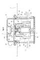
- FIG. 1 It is an exploded perspective view which shows one Embodiment of the full tank control valve which concerns on this invention. It is a perspective view of the same full tank regulation valve. It is sectional drawing in the line of arrow AA of FIG. It is a schematic explanatory drawing when the same full tank regulation valve is attached to a fuel tank. It is a perspective view of the housing body which constitutes the housing in the same full tank regulation valve. It is an exploded perspective view of the float valve which constitutes the same full tank regulation valve. It is a front view of the housing body which constitutes the housing in the same full tank regulation valve.
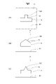
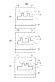
- a modified example of the second flow hole in the same full tank regulation valve is shown, (A) is an enlarged explanatory view showing the first modified example, (B) is an enlarged explanatory view showing the second modified example, and (C) is an enlarged explanatory view. It is an enlarged explanatory view which shows the 3rd modification.
- a modified example of the second flow hole in the same full tank regulation valve is shown, (A) is an enlarged explanatory view showing a fourth modified example, (B) is an enlarged explanatory view showing a fifth modified example, and (C) is an enlarged explanatory view. It is an enlarged explanatory view which shows the 6th modification. It is sectional drawing of the same full tank regulation valve in a state where the full tank regulation is done. FIG.
- FIG. 3 is a cross-sectional view of the full tank regulation valve in a state where the fuel liquid level in the valve chamber is lowered after the full tank regulation shown in FIG. It is sectional drawing of the same full tank regulation valve in the state which additional refueling was performed after the fuel liquid level in the valve chamber as shown in FIG. 11 fell.
- the full tank control valve 10 in this embodiment is attached above the fuel tank 1 as shown in FIGS. 3 and 4.
- a refueling pipe 2 for refueling fuel extends diagonally upward.
- a refueling port 3 is formed at the upper end of the refueling pipe 2.
- a refueling nozzle 4 is inserted into the refueling pipe 2 via a refueling port 3, and fuel is refueled from the refueling nozzle 4 to the inside of the fuel tank 1. It has become like.
- the full tank control valve 10 in this embodiment has a peripheral wall 21 and a partition wall 23, and is a valve that communicates downward into the fuel tank 1 via the partition wall 23.
- a ventilation chamber R communicating with the outside of the fuel tank 1 is provided above the chamber V, and an opening 25 for communicating the valve chamber V and the ventilation chamber R is formed on the partition wall 23, inside the housing 15 and the valve chamber V.
- It has a float valve 40 that is accommodated so as to be able to move up and down, opens and closes the opening 25, and rises when refueling into the fuel tank 1 to close the opening 25.
- fuel means liquid fuel (including fuel droplets), and “fuel vapor” means evaporated fuel.
- fuel liquid level L1 the fuel liquid level in the fuel tank 1
- fuel liquid level L2 the fuel liquid level in the valve chamber V
- the housing 15 in this embodiment has a substantially tubular housing body 20, a lower cap 30 mounted below the housing body 20, and an upper cover 35 mounted above the housing body 20. are doing.
- the housing body 20 has a substantially cylindrical peripheral wall 21, and a partition wall 23 is arranged above the peripheral wall 21.
- a plurality of first locking claws 21a are projected below the peripheral wall 21 at equal intervals in the circumferential direction (here, four).
- a plurality of second locking claws 21b are projected above the peripheral wall 21 at equal intervals in the circumferential direction (here, four).
- a ring mounting groove 27 is formed on the upper inner circumference of the peripheral wall 21, and the disk-shaped partition wall 23 is arranged inside the ring mounting groove 27.
- a seal ring 28 is mounted in the ring mounting groove 27.
- a circular opening 25 is formed in the center of the partition wall 23.
- a plurality of thin-walled plate-shaped guide ribs 29 are formed on the inner circumference of the peripheral wall 21 at a position from the middle of the peripheral wall 21 to the partition wall 23.
- the lower cap 30 has a plurality of through holes 31 formed at the bottom thereof and a plurality of locking holes 32 formed on the outer periphery thereof.
- the upper cover 35 has a substantially hat shape with the upper part closed, and the first connecting pipe 37 and the second connecting pipe 38 extend from a predetermined portion of the peripheral wall 36 in the outer diameter direction.
- the first connecting pipe 37 is connected to the tube 5a connected to the canister 5 arranged outside the fuel tank 1.
- a tube 6a connected to a valve 6 such as a check valve or a cut valve is connected to the second connecting pipe 38.
- the first connecting pipe 37 extends from a fuel vapor discharge port (not shown) provided on the peripheral wall 36, and the second connecting pipe 38 extends from a communication hole 38a (see FIG. 3) provided on the peripheral wall 36.
- a plurality of frame-shaped locking pieces 39 extend from below the peripheral wall 36. Then, by locking each locking piece 39 to each second locking claw 21b of the housing body 20, the seal ring 28 mounted in the ring mounting groove 27 is placed on the inner circumference of the peripheral wall 36 of the upper cover 35. The upper cover 35 is mounted above the housing body 20 in the abutted state (see FIG. 3). As a result, a ventilation chamber R communicating with the outside of the fuel tank 1 is formed above the partition wall 23 (see FIG. 3).
- a float valve 40 that opens and closes the opening 25 is located between the lower cap 30 and the float valve urging spring S (hereinafter, simply “urging spring S”) formed of a coil spring. It is designed to be accommodated and arranged so that it can be raised and lowered with the intervention of).
- the float valve 40 rises due to its own buoyancy and the urging force of the urging spring S when the fuel is immersed, and descends by its own weight when the fuel is not immersed.
- the float valve 40 of this embodiment is mounted on a lower member 41 that generates buoyancy during fuel immersion and above the lower member 41, and is relatively relative to the lower member 41. It has an upper member 45 that moves up and down and is brought into contact with and separated from the opening 25. Further, the float valve 40 has a seal valve body 50 mounted on the upper member 45 and an intermediate valve body 55 arranged between the lower member 41 and the upper member 45.
- the seal valve body 50 is composed of a shaft portion 51 having a protrusion 51a on the outer periphery of the lower end portion and a seal flange 52 extending in an annular shape from the peripheral edge of the upper end portion of the shaft portion 51, and is made of an elastic material such as rubber or an elastic elastomer. It is integrally formed. Further, the shaft portion 51 is formed with a communication hole 53 extending in the axial direction of the float valve 40 and opening upward and downward (see FIG. 3).
- the lower member 41 has a cylindrical lower main body 42, an upper member assembling portion 43 that protrudes from the center of the upper part of the lower main body 42 and has a smaller diameter than the lower main body 42, and an upper portion of the upper member assembling portion 43. It has an intermediate valve body assembly portion 44 that protrudes from the center and has a smaller diameter than the upper member assembly portion 43.
- the intermediate valve body 55 is mounted on the outer periphery of the intermediate valve body assembly portion 44.
- the intermediate valve body 55 has a substantially hat shape in which the upper portion is closed and a plurality of frame-shaped locking frames 56 are provided on the outer periphery thereof.
- the upper center of the intermediate valve body 55 is supported by the support protrusion 44b, and a plurality of locking frames 56 can be locked to the annular protrusion 44a.
- the intermediate valve body 55 is tiltably mounted on the valve body assembly portion 44. Further, the intermediate valve body 55 is always in contact with the lower end portion of the shaft portion 51 of the seal valve body 50 to close the lower opening 53a of the communication hole 53 provided in the coaxial portion 51 (FIG. FIG. 3). As shown in FIG. 11, the lower opening 53a of the communication hole 53 of the shaft portion 51 opens when the lower member 41 descends with respect to the upper member 45.
- the upper member 45 is a ceiling portion 46, a substantially cylindrical peripheral wall 47 extending from the back surface (lower surface) of the ceiling portion 46, and the back surface of the ceiling portion 46, and is inside the peripheral wall 47. It has a plurality of elastic engagement pieces 48 (see FIG. 3) extending from the ceiling.
- the ceiling portion 46 has a substantially disk shape, and a circular support hole 46a is formed in the center thereof. Further, a plurality of holes 46b are formed through the outer periphery of the ceiling portion 46. Further, inside each elastic engaging piece 48, an engaging hole 48a having an elongated hole shape extending with a predetermined length is provided (see FIG. 3).
- the shaft portion 51 is inserted from the front side of the support hole 46a, and the protrusion 51a is locked to the back peripheral edge of the support hole 46a to seal the upper member 45 on the surface (upper surface) side of the ceiling portion 46.
- the valve body 50 is attached. Further, by inserting the protruding engaged portion 43a of the lower member 41 into the engaging hole 48a of each elastic engaging piece 48, the upper member 45 moves up and down by a predetermined distance with respect to the lower member 41. It is designed to be assembled as possible. The upper member 45 can also be tilted with respect to the lower member 41.
- the float valve 40 in this embodiment has a multi-part configuration composed of a lower member 41, an upper member 45, and the like.
- a float valve for example, a float valve having a seal member made of an elastic material mounted above it.
- the shape and structure of the opening 25 are not particularly limited as long as the opening 25 can be opened and closed.
- the peripheral wall 21 of the housing body 20 constituting the housing 15 has a first distribution hole 60 and a first flow hole 60 for communicating the internal space of the fuel tank 1 and the internal space of the valve chamber V.
- Two flow holes 70 and a third flow hole 80 are formed.
- these flow holes 60, 70, 80 will be described with reference to FIGS. 5 and 7.
- the first flow hole 60 extends to the lower side of the peripheral wall 21 of the housing body 20 with a predetermined length L1 along the circumferential direction, and is predetermined in the axial direction of the housing 15 (the same direction as the axial direction of the float valve 40). It has a substantially elongated hole shape elongated in the circumferential direction, formed at a height of H1.
- the first flow hole 60 is arranged at a height that regulates full tank before additional refueling, and allows the internal space of the fuel tank 1 and the internal space of the valve chamber V to communicate with each other in a state where the fuel tank 1 is not submerged. , It is formed with an opening area that enables continuous refueling from the refueling nozzle 4.
- the air inflow speed from the second flow hole 70 and the third flow hole 80 cannot keep up with the continuous refueling speed from the refueling nozzle 4, and the inside of the valve chamber V.
- the fuel liquid level L2 rises, the float valve 40 closes the opening 25, and continuous refueling from the refueling nozzle 4 is stopped (see FIG. 10).
- non-submerged state in the first flow hole means a state in which the fuel tank is opened without being blocked by the liquid fuel and the inside of the fuel tank and the valve chamber are in communication with each other.
- the “submerged state” means a state in which the communication between the inside of the fuel tank and the valve chamber is cut off by being blocked by the liquid fuel.
- a pair of first flow holes 60, 60 are formed at locations facing the peripheral wall 21 in the circumferential direction (see FIG. 3). Further, as shown in FIG. 7, each first flow hole 60 is positioned so that both ends in the circumferential direction are aligned with the first locking claws 21a and 21a protruding from the peripheral wall 21 in the circumferential direction. It is provided in.
- the flow path area of the first flow hole 60 is larger than the flow path area of the second flow hole 70 and the third flow hole 80, and the flow path area of the first flow hole 60 is larger than that of the second flow hole 70 and the third flow hole 80. Is located downward in the axial direction of the housing 15.
- the second flow hole 70 is formed above the peripheral wall 21 of the housing body 20 above the first flow hole 60 and smaller than the first flow hole 60.
- the second distribution hole 70 is arranged at a height that regulates additional refueling, enables additional refueling in a non-submerged state (see FIG. 11), and is configured to stop additional refueling in a submerged state. (See FIG. 12).
- the second flow hole 70 in this embodiment has a substantially elongated hole shape elongated in the circumferential direction, extending along the circumferential direction at a predetermined length L2 and formed at a predetermined height H2 in the axial direction of the housing 15. None. Further, the circumferential length L2 of the second flow hole 70 is shorter than the circumferential length L1 of each first flow hole 60, and the axial height H2 of each second flow hole 70 is. The height of each first flow hole 60 in the axial direction is lower than H1. As a result, the second flow hole 70 is formed smaller than the first flow hole 60.
- a pair of second flow holes 70, 70 are formed at locations facing the peripheral wall 21 in the circumferential direction (see FIG. 3). Further, as shown in FIG. 7, each second flow hole 70 is arranged at the center in the circumferential direction of the long hole-shaped first flow hole 60.
- the flow path area of the second flow hole 70 is smaller than the flow path area of the first flow hole 60 and larger than the flow path area of the third flow hole 80, and the shaft of the housing 15 is provided. It is located between the first flow hole 60 and the third flow hole 80 in the direction.
- the third distribution hole 80 is formed above the peripheral wall 21 of the housing body 20 above the second distribution hole 70 and smaller than the second distribution hole 70.
- the third distribution hole 80 is always maintained in a non-submerged state even when the first flow hole 60 and the second flow hole 0 are submerged by fuel, except when the vehicle rolls over or is turned over. (See FIGS. 3 and 10-12).
- the third flow hole 80 is in the valve chamber V from the fuel liquid level L1 in the fuel tank 1 even when the first flow hole 60 and the second flow hole 70 are in the liquid state without being submerged. If the fuel liquid level L2 is high, the air in the fuel tank 1 is configured to flow into the valve chamber V (see FIG. 10).
- the fuel liquid level L2 in the valve chamber V is the fuel in the fuel tank 1. If it is higher than the liquid level L1, the third flow hole 80 is configured to allow the air in the fuel tank 1 to flow into the valve chamber V.
- the third flow hole 80 in this embodiment has a circular shape, and its inner diameter D is smaller than the circumferential length L2 and the axial height H2 of the second flow hole 70. As a result, the third flow hole 80 is formed smaller than the second flow hole 70.
- a pair of third flow holes 80, 80 are formed at locations facing the peripheral wall 21 in the circumferential direction (see FIG. 3). Further, as shown in FIG. 7, each third flow hole 80 is the center of the circumferential second flow hole 70 in the circumferential direction, and is adjacent to the second flow hole protruding from the peripheral wall 21 in the circumferential direction. It is provided so as to be located between the locking claws 21b and 21b.
- the flow path area of the third flow hole 80 is smaller than the flow path areas of the first flow hole 60 and the second flow hole 70, and the third flow hole 80 is located at the uppermost position in the axial direction of the housing 15. ing.
- the shapes of the first flow hole, the second flow hole, and the third flow hole are, for example, triangular hole shape, square hole shape, polygonal hole shape of pentagon or more, rhombic hole shape, round hole shape, and elliptical shape. It may be in the shape of a hole, a slit hole (a pore thinner than a long hole), etc., and the size of each flow hole, that is, the size relationship of the flow path area of each flow hole (the flow path of the first flow hole).
- the area is not particularly limited as long as the area> the flow path area of the second flow hole> the flow path area of the third flow hole) is maintained.
- the second distribution hole may have the shape shown in FIGS. 8 and 9.
- These second distribution holes 70A, 70B, 70C, 70D, 70E, 70F have a base 71 extending along the circumferential direction of the peripheral wall 21 and an upper end of the base 71 toward the upper side of the peripheral wall 21 from the base 71. It is composed of a notch 73 having a narrow width. The details will be described below.
- the second flow hole 70A shown in FIG. 8A has a base portion 71 extending at a constant height along the circumferential direction of the peripheral wall 21, and an upper end of the base portion 71 from the center in the circumferential direction toward the upper side of the peripheral wall 21. It is composed of a notch portion 73 that is narrower than the base portion 71 and extends with a constant width. The channel area of the notch 73 is smaller than the channel area of the base 71.
- the second flow hole 70B shown in FIG. 8B has a base portion 71 extending at a constant height along the circumferential direction of the peripheral wall 21, and an upper end of the base portion 71 from both ends in the circumferential direction above the peripheral wall 21. It is composed of a notch portion 73 that extends in a tapered shape that gradually narrows toward the direction and has a substantially triangular shape.
- the notch portion 73 has the same circumferential length as the base portion 71 at the lower end side thereof, but the flow path area thereof is smaller than the flow path area of the base portion 71.
- the second flow hole 70C shown in FIG. 8C has a base portion 71 extending at a constant height along the circumferential direction of the peripheral wall 21, and an upper end of the base portion 71, which is above the peripheral wall 21 from the central portion in the circumferential direction. It is composed of a notch portion 73 that extends in a tapered shape that gradually narrows toward the direction and has a substantially triangular shape. The channel area of the notch 73 is smaller than the channel area of the base 71.
- the second flow hole 70D shown in FIG. 9 (A) has a base portion 71 extending at a constant height along the circumferential direction of the peripheral wall 21, and an upper end of the base portion 71, which is above the peripheral wall 21 from two locations in the circumferential direction. It is composed of a pair of notches 73, 73 that are narrower than the base 71 and extend with a constant width toward the base 71. The flow path area of each notch 73 is smaller than the flow path area of the base 71.
- the second flow hole 70E shown in FIG. 9B is a base portion 71 having a recess 71a extending downward along the circumferential direction of the peripheral wall 21 and denting downward in the center of the upper end portion, and the upper end of the base portion 71. It is composed of a pair of notches 73, 73 extending from both side edges in the circumferential direction of the recess 71a toward the upper side of the peripheral wall 21 with a width narrower and a constant width than the base portion 71. The flow path area of each notch 73 is smaller than the flow path area of the base 71 provided with the recess 71a.
- the second flow hole 70F shown in FIG. 9C has a base portion 71 extending along the circumferential direction of the peripheral wall 21 and having a convex portion 71b extending upward in the center of the upper end portion, and a base portion 71 of the base portion 71. It is composed of a pair of notches 73, 73 which are the upper ends of the convex portions 71b and extend from both ends in the circumferential direction toward the upper side of the peripheral wall 21 with a width narrower and a constant width than the base portion 71. The flow path area of each notch 73 is smaller than the flow path area of the base 71.
- the first flow hole side is formed to have a shape consisting of a base portion and a narrow notch portion, or both the first flow hole and the second flow hole are formed of a base portion and a narrow notch portion. It may be shaped.
- the second distribution hole 70 is provided at a position deviated toward the first distribution hole 60, and is slightly separated from the third distribution hole 30, but the first distribution hole 70 is provided.
- the positions of the holes, the second flow hole, and the third flow hole are in the positional relationship of each flow hole (the first flow hole is located at the bottom, the third flow hole is located at the top, and the second flow hole is the first. It is not particularly limited as long as it is located between the 1st flow hole and the 3rd flow hole).
- the second flow hole is formed at a position overlapping the circumferential range of the first flow hole (wrapping position), and the third flow hole overlaps with the circumferential range of the second flow hole (the position where the second flow hole overlaps the circumferential range (wrapping position). It is preferably formed at the wrapping position).
- a set of flow holes 60, 70, 80 are provided on one side of the peripheral wall 21 in the circumferential direction, and a set of flow holes 60, on the other side of the peripheral wall 21 in the circumferential direction.
- 70 and 80 are provided (see FIG. 3), for example, one set of distribution holes 60, 70 and 80 may be provided in three or more sets, and the number and arrangement of each distribution hole is not particularly limited.
- this full tank regulation valve 10 enables quick additional refueling after full tank regulation as follows. The details will be described below.
- the air in the fuel tank 1 passes through the flow holes 60, 70, 80, flows into the valve chamber V, and further passes through the opening 25. Then, it flows into the ventilation chamber R and is discharged to the canister 5 outside the fuel tank 1 via the tube 5a. In this way, the air in the fuel tank 1 is discharged to the outside of the fuel tank 1, so that fuel can be refueled in the fuel tank 1.
- the fuel flows into the valve chamber V through the first distribution hole 60. Then, the lower member 41 is immersed in the fuel that has flowed into the valve chamber V, so that the float valve 40 gradually rises. Until the first flow hole 60 is submerged, the fuel liquid level L1 in the fuel tank 1 and the fuel liquid level L2 in the valve chamber V are at the same height.
- the fuel liquid level L2 rises at once in the valve chamber V, and the second flow hole 70 is also submerged.
- the float valve 40 is further raised, the seal valve body 50 comes into contact with the back peripheral portion of the opening 25, and the opening 25 is closed.
- the air flow between the valve chamber V and the ventilation chamber R through the opening 25 is cut off.
- the fuel in the fuel tank 1 rises in the refueling pipe 2, and the fuel comes into contact with the full tank detection sensor (not shown) of the refueling nozzle 4 inserted into the refueling pipe 2 through the refueling port 3 to fill the tank. Is detected, refueling into the fuel tank 1 is stopped and full tank regulation is performed.
- the third flow hole 80 is open without being submerged (see FIG. 10).
- the fuel liquid level L2 in the valve chamber V is higher than the fuel liquid level L1 in the fuel tank 1
- the third flow hole 80 causes the air in the fuel tank 1 to flow into the valve chamber V. It is configured (see FIG. 10). Therefore, as shown by the arrow F1 in FIG. 10, the air in the fuel tank 1 flows into the valve chamber V from the third flow hole 80. Then, as shown in FIG. 11, the fuel liquid level L2 in the valve chamber V descends, and the amount of fuel immersed in the lower member 41 decreases.
- the fuel liquid level L2 in the valve chamber V descends until the second flow hole 70 does not submerge and opens, the inside of the fuel tank 1 and the inside of the valve chamber V communicate with each other through the second flow hole 70.
- the fuel liquid level L2 in the valve chamber V descends until it becomes the same height as the fuel liquid level L1 in the fuel tank 1.
- the intermediate valve body 55 separates from the seal valve body 50, and the lower opening 53a of the communication hole 53 of the seal valve body 50 opens (see FIG. 11). ..
- the opening 25 communicates with the valve chamber V and the ventilation chamber R through the communication hole 53 of the seal valve body 50.
- the first flow hole 60 is maintained in a submerged state (the closed state is maintained), but the second flow hole 70 and the opening 25 are opened without being submerged. Therefore, as shown by the arrow F2 in FIG. 11, the air in the fuel tank 1 can be discharged to the outside of the fuel tank 1 through the second flow hole 70 and the opening 25 (here, the air is discharged).
- FIG. 12 additional refueling into the fuel tank 1 becomes possible until the second flow hole 70 is closed.
- the air in the fuel tank 1 flows into the valve chamber V from the third flow hole 80 in which the state of not being submerged is maintained, and the air in the valve chamber V flows into the valve chamber V.
- the lower member 41 descends with respect to the upper member 45 to which the abutting seal valve body 50 attached to the back peripheral edge portion of the opening 25 is attached.
- the first flow hole 60 and the second flow hole 70 are set in a state of not being submerged in the peripheral wall 21 of the housing 15 even if the first flow hole 60 and the second flow hole 70 are submerged, and air flows into the valve chamber V. Since the third flow hole 80 is provided so that the air can easily flow into the valve chamber V from the third flow hole 80 after the full tank regulation shown in FIG. 10 (see arrow F1 in FIG. 10). ), The descending speed of the fuel liquid level L2 in the valve chamber V after the full tank regulation can be increased, and additional refueling can be quickly performed after the full tank regulation.
- the float valve 40 is mounted on the lower member 41 and above the lower member 41, moves up and down relative to the lower member 41, and is brought into contact with and separated from the opening 25.
- the upper member 45 is formed with a communication hole 53 extending in the axial direction of the float valve 40 and opening upward and downward, and the lower member 41 is formed in the communication hole 53.
- the lower opening 53a is configured to open when descending with respect to the member 45.
- the lower opening 53a of the communication hole 53 formed in the upper member 45 opens (see FIG. 11), so that the upper member 45 hits the opening 25. Even if they are in contact with each other, it is possible to enable air flow between the valve chamber V and the ventilation chamber R, and it is possible to secure a flow passage for the air flowing into the valve chamber V from the third flow hole 80. As a result, the amount of airflow of the gas flowing into the valve chamber V from the third flow hole 80 can be increased (air flows smoothly because the air flow passage is secured), and the fuel in the valve chamber V can be increased.
- the descending speed of the liquid level L2 can be further increased to facilitate the opening of the second flow hole 70, and additional refueling after the full tank regulation can be performed more quickly.
- the second flow holes 70A, 70B, 70C, 70D, 70E, 70F have a base 71 extending along the circumferential direction of the peripheral wall 21 and a peripheral wall 21 from the upper end of the base 71.
- it is composed of a notch 73 having a width narrower than that of the base 71 toward the upper side of the above, the following effects are obtained.
- the base 71 is first liquid at the time of refueling the fuel tank 1 or at the time of additional refueling.
- the notch 73 having a narrower width is submerged, so that the second flow hole can be suppressed from submerging at once, and the fuel blowout from the fuel filler port 3 can be suppressed.
- the first flow hole is composed of a base and a narrow notch, and both the first flow hole and the second flow hole are composed of a base and a narrow notch. In the same case, the same effect can be obtained.
- the present invention is not limited to the above-described embodiments, and various modified embodiments are possible within the scope of the gist of the present invention, and such embodiments are also included in the scope of the present invention. ..
Abstract
Provided is a full tank regulation valve that can quickly perform additional refueling after full tank regulation. This full tank regulation valve 10 comprises a housing 15 that has an opening 25, and a float valve 40 that opens and closes the opening 25, and also comprises a first circulation hole 60 formed in a peripheral wall 21, a second circulation hole 70 formed smaller than and further above the first circulation hole 60, and a third circulation hole 80 formed smaller than and further above the second circulation hole 70, wherein refueling is possible when the first circulation hole 60 is not submerged, additional refueling is possible until the second circulation hole 70 is submerged in a state in which the first circulation hole 60 is submerged and the second circulation hole 70 and the opening 25 are not submerged, the third circulation hole 80 is always open without being submerged, and the fuel liquid level in the valve chamber is lowered by the air flowing into the valve chamber from the third circulation hole 80.
Description
本発明は、追加給油を可能とする満タン規制バルブに関する。
The present invention relates to a full tank control valve that enables additional refueling.
燃料タンクには、燃料給油時の満タンを検知して閉弁し、過給油を防止する満タン規制バルブが設けられていることがある。
The fuel tank may be equipped with a full tank regulation valve that detects when the fuel is full and closes it to prevent overfueling.
この種のバルブとして、例えば、下記特許文献1には、上部空間と、下部室と、上部空間と下部室とを連通させる連通孔と、下部室内への燃料流入により上昇して連通孔を閉塞するフロート体とを有し、下部室は、その側部にのみ燃料の主流入部を備え、燃料タンク内の燃料の液面レベルが主流入部に達した後の下部室への燃料の流入により、燃料タンクの内圧を上昇させて満タン検知させる、過給油防止バルブが記載されている。
As a valve of this type, for example, in Patent Document 1 below, a communication hole for communicating an upper space, a lower chamber, an upper space and a lower chamber, and a communication hole which rises due to fuel inflow into the lower chamber and closes the communication hole. The lower chamber is provided with a main inflow portion of fuel only on the side thereof, and the inflow of fuel into the lower chamber after the liquid level level of the fuel in the fuel tank reaches the main inflow portion is provided. An overfuel prevention valve that raises the internal pressure of the fuel tank to detect full tank is described.
また、特許文献1の図7~10に示す第3実施例では、ケーシング体と、その下方に配置されたカップ体とを有しており、同カップ体は、上方が開口し且つケーシング体よりも拡径しており、ケーシング体の下縁部とカップ体の上縁部の間に、主流入部が設けられている。更に、ケーシング体の下方には、側部オリフィスが形成されている。
Further, in the third embodiment shown in FIGS. 7 to 10 of Patent Document 1, the casing body and the cup body arranged below the casing body are provided, and the cup body has an opening at the upper side and is more than the casing body. Is also expanded in diameter, and a main inflow portion is provided between the lower edge portion of the casing body and the upper edge portion of the cup body. Further, a side orifice is formed below the casing body.
そして、タンク内に燃料が給油されると、主流入部から下部室内に燃料が流入して、下部室内の燃料液面が上昇すると共に、フロートが上昇していく。そして、フロートが連通孔を閉塞すると、満タン検知がなされて、給油が一旦停止される。なお、この状態では、側部オリフィスは液没している(特許文献1の図8参照)。その後、側部オリフィスを通じて、燃料タンク内の空気が下部室内に徐々に入り込んで、フロートが下降して、下部室内の燃料液面が下がって、満タン規制が解除されるので、追加給油が可能となる。
Then, when the fuel is refueled in the tank, the fuel flows into the lower chamber from the main inflow portion, the fuel liquid level in the lower chamber rises, and the float rises. Then, when the float closes the communication hole, full tank detection is performed and refueling is temporarily stopped. In this state, the side orifice is submerged (see FIG. 8 of Patent Document 1). After that, the air in the fuel tank gradually enters the lower chamber through the side orifice, the float drops, the fuel liquid level in the lower chamber drops, and the full tank regulation is lifted, so additional refueling is possible. It becomes.
上記特許文献1の過給油防止バルブでは、フロートが上昇して満タン検知がなされた後、側部オリフィスから流入する空気によって、下部室内の燃料液面が下がるが、側部オリフィスは液没して閉塞されているため、下部室内に空気が流入しにくく、燃料液面の下降速度が比較的遅い。そのため、満タン検知から追加給油が可能となるまでに、時間がかかっていた。
In the superlubrication prevention valve of Patent Document 1, after the float rises and full tank detection is performed, the fuel liquid level in the lower chamber is lowered by the air flowing in from the side orifice, but the side orifice is submerged. Because it is blocked, it is difficult for air to flow into the lower chamber, and the rate of descent of the fuel liquid level is relatively slow. Therefore, it took a long time from the detection of full tank to the possibility of additional refueling.
したがって、本発明の目的は、満タン規制がなされた後、追加給油を迅速に行うことができる、満タン規制バルブを提供することにある。
Therefore, an object of the present invention is to provide a full tank regulation valve capable of promptly performing additional refueling after the full tank regulation is made.
上記目的を達成するため、本発明に係る満タン規制バルブは、周壁及び仕切壁を有しており、前記仕切壁を介して、下方に燃料タンク内に連通する弁室、上方に燃料タンク外に連通する通気室が設けられ、前記仕切壁に前記弁室と前記通気室とを連通する開口部が形成された、ハウジングと、前記弁室内に昇降可能に収容されて前記開口部を開閉し、燃料タンク内への給油時に上昇して前記開口部を閉塞するフロート弁とを有しており、前記周壁に形成され、燃料タンク内と弁室内とを互いに連通させて、燃料タンク内の燃料を弁室内に流入させる第1流通孔と、前記周壁の、前記第1流通孔よりも上方に、同第1流通孔よりも小さく形成されており、燃料タンク内と弁室内とを互いに連通させて、燃料タンク内の燃料を弁室内に流入させる第2流通孔と、前記周壁の、前記第2流通孔よりも上方に、同第2流通孔よりも小さく形成されており、燃料タンク内と弁室内とを互いに連通させて、燃料タンク内の空気を弁室内に流入させる第3流通孔とを有しており、前記第1流通孔は、追加給油前の満タン規制を行う高さに配置され、液没していない状態で給油ノズルからの連続給油を可能とし、液没状態で給油ノズルからの連続給油を停止するように構成され、前記第2流通孔は、追加給油規制を行う高さに配置され、液没していない状態で追加給油を可能とし、液没状態で追加給油を停止するように構成されており、前記第3流通孔が液没しておらず、前記第1流通孔及び前記第2流通孔が液没した状態で、前記弁室内の燃料液面が前記燃料タンク内の燃料液面より高ければ、前記第3流通孔は、前記弁室内に燃料タンク内の空気を流入させるように構成されていることを特徴とする。
In order to achieve the above object, the full tank control valve according to the present invention has a peripheral wall and a partition wall, and the valve chamber communicating downward into the fuel tank and the outside of the fuel tank above through the partition wall. A ventilation chamber is provided, and an opening for communicating the valve chamber and the ventilation chamber is formed in the partition wall. The housing and the valve chamber are housed so as to be able to move up and down to open and close the opening. It has a float valve that rises when refueling into the fuel tank and closes the opening, is formed on the peripheral wall, communicates the inside of the fuel tank and the valve chamber with each other, and fuels in the fuel tank. The fuel tank and the valve chamber are communicated with each other by forming a first flow hole for flowing the fuel into the valve chamber and a peripheral wall above the first flow hole and smaller than the first flow hole. The second flow hole for allowing the fuel in the fuel tank to flow into the valve chamber, and the peripheral wall formed above the second flow hole and smaller than the second flow hole, are formed in the fuel tank. It has a third flow hole that communicates with the valve chamber and allows the air in the fuel tank to flow into the valve chamber, and the first flow hole has a height that regulates full tank before additional refueling. It is arranged to enable continuous refueling from the refueling nozzle when it is not submerged, and is configured to stop continuous refueling from the refueling nozzle when it is submerged. It is arranged at a height, enables additional refueling in a non-submerged state, and is configured to stop additional refueling in a submerged state. If the fuel liquid level in the valve chamber is higher than the fuel liquid level in the fuel tank while the 1 flow hole and the second flow hole are submerged, the third flow hole is in the fuel tank in the valve chamber. It is characterized by being configured to allow the air to flow in.
本発明によれば、燃料タンク内に燃料を給油すると、第1流通孔を通じて弁室内に燃料が流入して、弁室内での燃料液面が上昇していき、燃料により第1流通孔が液没すると共に、フロート弁が上昇して開口部が閉塞されると、弁室と通気室との空気流通が遮断されるので、それ以上の給油が不能となり満タン規制がなされる。その後、第3流通孔から燃料タンク内の空気が弁室内に流入することで、弁室内の燃料液面が下降していき、第2流通孔が液没しない状態となると(開口すると)、再び第2流通孔が燃料により液没するまで追加給油が可能となる。
According to the present invention, when fuel is refueled in the fuel tank, the fuel flows into the valve chamber through the first flow hole, the fuel liquid level in the valve chamber rises, and the fuel causes the first flow hole to become liquid. When the float valve rises and the opening is closed as it sinks, the air flow between the valve chamber and the ventilation chamber is blocked, so that further refueling becomes impossible and full tank regulation is performed. After that, when the air in the fuel tank flows into the valve chamber from the third flow hole, the fuel liquid level in the valve chamber descends, and when the second flow hole is in a state where it does not submerge (when it opens), it is again. Additional refueling is possible until the second flow hole is submerged by fuel.
そして、ハウジングの周壁に、第1流通孔及び第2流通孔が液没された状態でも、液没せずに開口して、弁室内に空気を流入させる第3流通孔を設けたので、上記の満タン規制後に、第3流通孔から弁室内に空気を流入しやすくして、満タン規制後の弁室内での燃料液面の下降速度を上昇させることができ、満タン規制後に追加給油を迅速に行うことができる。
Further, the peripheral wall of the housing is provided with a third flow hole for allowing air to flow into the valve chamber by opening the first flow hole and the second flow hole without being submerged even when the first flow hole and the second flow hole are submerged. It is possible to increase the rate of descent of the fuel liquid level in the valve chamber after the full tank regulation by making it easier for air to flow into the valve chamber from the third distribution hole after the full tank regulation, and additional refueling after the full tank regulation. Can be done quickly.
(満タン規制バルブの一実施形態)
以下、図面を参照して、本発明に係る満タン規制バルブの、一実施形態について説明する。 (One embodiment of a full tank regulation valve)
Hereinafter, an embodiment of the full tank control valve according to the present invention will be described with reference to the drawings.
以下、図面を参照して、本発明に係る満タン規制バルブの、一実施形態について説明する。 (One embodiment of a full tank regulation valve)
Hereinafter, an embodiment of the full tank control valve according to the present invention will be described with reference to the drawings.
また、この実施形態における満タン規制バルブ10は、図3や図4に示すように、燃料タンク1の上方に取付けられている。燃料タンク1の一側面からは、燃料を給油するための給油管2が、斜め上方に向けて延設されている。この給油管2の上端に、給油口3が形成されている。また、図4に示すように、給油管2には、給油口3を介して給油ノズル4が差し込まれるようになっており、この給油ノズル4から、燃料タンク1の内部に燃料が給油されるようになっている。
Further, the full tank control valve 10 in this embodiment is attached above the fuel tank 1 as shown in FIGS. 3 and 4. From one side of the fuel tank 1, a refueling pipe 2 for refueling fuel extends diagonally upward. A refueling port 3 is formed at the upper end of the refueling pipe 2. Further, as shown in FIG. 4, a refueling nozzle 4 is inserted into the refueling pipe 2 via a refueling port 3, and fuel is refueled from the refueling nozzle 4 to the inside of the fuel tank 1. It has become like.
図1及び図3に示すように、この実施形態における満タン規制バルブ10は、周壁21及び仕切壁23を有しており、仕切壁23を介して、下方に燃料タンク1内に連通する弁室V、上方に燃料タンク1外に連通する通気室Rが設けられ、仕切壁23に弁室Vと通気室Rとを連通する開口部25が形成された、ハウジング15と、弁室V内に昇降可能に収容されて開口部25を開閉し、燃料タンク1内への給油時に上昇して開口部25を閉塞するフロート弁40とを有している。
As shown in FIGS. 1 and 3, the full tank control valve 10 in this embodiment has a peripheral wall 21 and a partition wall 23, and is a valve that communicates downward into the fuel tank 1 via the partition wall 23. A ventilation chamber R communicating with the outside of the fuel tank 1 is provided above the chamber V, and an opening 25 for communicating the valve chamber V and the ventilation chamber R is formed on the partition wall 23, inside the housing 15 and the valve chamber V. It has a float valve 40 that is accommodated so as to be able to move up and down, opens and closes the opening 25, and rises when refueling into the fuel tank 1 to close the opening 25.
なお、以下の説明において、「燃料」とは、液体の燃料(燃料の飛沫も含む)を意味し、「燃料蒸気」とは、蒸発した燃料を意味するものとする。また、以下の説明において、燃料タンク1内の燃料液面を「燃料液面L1」とし、弁室V内の燃料液面を「燃料液面L2」とする(図10参照)。
In the following description, "fuel" means liquid fuel (including fuel droplets), and "fuel vapor" means evaporated fuel. Further, in the following description, the fuel liquid level in the fuel tank 1 is referred to as “fuel liquid level L1”, and the fuel liquid level in the valve chamber V is referred to as “fuel liquid level L2” (see FIG. 10).
この実施形態におけるハウジング15は、略筒状をなしたハウジング本体20と、該ハウジング本体20の下方に装着される下部キャップ30と、前記ハウジング本体20の上方に装着される上部カバー35とを有している。
The housing 15 in this embodiment has a substantially tubular housing body 20, a lower cap 30 mounted below the housing body 20, and an upper cover 35 mounted above the housing body 20. are doing.
前記ハウジング本体20は、略円筒状をなした周壁21を有しており、その上方には仕切壁23が配置されている。周壁21の下方には、複数の第1係止爪21aが、周方向に均等な間隔を空けて突設されている(ここでは4個)。また、周壁21の上方には、複数の第2係止爪21bが、周方向に均等な間隔を空けて突設されている(ここでは4個)。更に周壁21の上方内周には、リング装着溝27が形成されており、このリング装着溝27の内側に、円板状をなした前記仕切壁23が配置されている。リング装着溝27には、シールリング28が装着されるようになっている。また、仕切壁23の中央に、円形状の開口部25が形成されている。更に図3に示すように、周壁21の内周であって、その高さ方向途中から前記仕切壁23に至る位置には、薄肉板状をなしたガイドリブ29が、複数形成されている。
The housing body 20 has a substantially cylindrical peripheral wall 21, and a partition wall 23 is arranged above the peripheral wall 21. A plurality of first locking claws 21a are projected below the peripheral wall 21 at equal intervals in the circumferential direction (here, four). Further, a plurality of second locking claws 21b are projected above the peripheral wall 21 at equal intervals in the circumferential direction (here, four). Further, a ring mounting groove 27 is formed on the upper inner circumference of the peripheral wall 21, and the disk-shaped partition wall 23 is arranged inside the ring mounting groove 27. A seal ring 28 is mounted in the ring mounting groove 27. Further, a circular opening 25 is formed in the center of the partition wall 23. Further, as shown in FIG. 3, a plurality of thin-walled plate-shaped guide ribs 29 are formed on the inner circumference of the peripheral wall 21 at a position from the middle of the peripheral wall 21 to the partition wall 23.
前記下部キャップ30は、その底部に複数の通口31が形成されていると共に、その外周に複数の係止孔32が形成されている。この下部キャップ30の各係止孔32に、ハウジング本体20の各第1係止爪21aをそれぞれ係止させることで、ハウジング本体20の下方に下部キャップ30が装着される。その結果、仕切壁23を介して、ハウジング下方に燃料タンク1の内部に連通する弁室Vが形成される(図3参照)。
The lower cap 30 has a plurality of through holes 31 formed at the bottom thereof and a plurality of locking holes 32 formed on the outer periphery thereof. By locking the first locking claws 21a of the housing body 20 to the locking holes 32 of the lower cap 30, the lower cap 30 is mounted below the housing body 20. As a result, a valve chamber V communicating with the inside of the fuel tank 1 is formed below the housing via the partition wall 23 (see FIG. 3).
一方、上部カバー35は、上方が閉塞した略ハット状をなしており、その周壁36の所定箇所から第1接続管37及び第2接続管38が外径方向に向けて延出している。図4に示すように、第1接続管37は、燃料タンク1の外部に配置されるキャニスタ5に連結されるチューブ5aが接続される。一方、第2接続管38には、チェックバルブやカットバルブ等のバルブ6に連結されるチューブ6aが接続される。
On the other hand, the upper cover 35 has a substantially hat shape with the upper part closed, and the first connecting pipe 37 and the second connecting pipe 38 extend from a predetermined portion of the peripheral wall 36 in the outer diameter direction. As shown in FIG. 4, the first connecting pipe 37 is connected to the tube 5a connected to the canister 5 arranged outside the fuel tank 1. On the other hand, a tube 6a connected to a valve 6 such as a check valve or a cut valve is connected to the second connecting pipe 38.
なお、第1接続管37は、周壁36に設けた図示しない燃料蒸気排出口から延出しており、第2接続管38は、周壁36に設けた連通孔38a(図3参照)から延出している。また、周壁36の下方からは、枠状の係止片39が複数延設されている。そして、各係止片39をハウジング本体20の各第2係止爪21bにそれぞれ係止させることで、リング装着溝27に装着されたシールリング28が、上部カバー35の周壁36の内周に当接した状態で、ハウジング本体20の上方に上部カバー35が装着される(図3参照)。その結果、仕切壁23を介して、その上方に燃料タンク1の外部に連通する通気室Rが形成されるようになっている(図3参照)。
The first connecting pipe 37 extends from a fuel vapor discharge port (not shown) provided on the peripheral wall 36, and the second connecting pipe 38 extends from a communication hole 38a (see FIG. 3) provided on the peripheral wall 36. There is. Further, a plurality of frame-shaped locking pieces 39 extend from below the peripheral wall 36. Then, by locking each locking piece 39 to each second locking claw 21b of the housing body 20, the seal ring 28 mounted in the ring mounting groove 27 is placed on the inner circumference of the peripheral wall 36 of the upper cover 35. The upper cover 35 is mounted above the housing body 20 in the abutted state (see FIG. 3). As a result, a ventilation chamber R communicating with the outside of the fuel tank 1 is formed above the partition wall 23 (see FIG. 3).
上記弁室V内には、前記開口部25を開閉するフロート弁40が、前記下部キャップ30との間で、コイルスプリングからなるフロート弁用付勢バネS(以下、単に「付勢バネS」ともいう)を介在させた状態で、昇降可能に収容配置されるようになっている。このフロート弁40は、燃料浸漬時に自身の浮力及び付勢バネSの付勢力で上昇し、燃料の非浸漬時に自重で下降する。
In the valve chamber V, a float valve 40 that opens and closes the opening 25 is located between the lower cap 30 and the float valve urging spring S (hereinafter, simply "urging spring S") formed of a coil spring. It is designed to be accommodated and arranged so that it can be raised and lowered with the intervention of). The float valve 40 rises due to its own buoyancy and the urging force of the urging spring S when the fuel is immersed, and descends by its own weight when the fuel is not immersed.
図1及び図6に示すように、この実施形態のフロート弁40は、燃料浸漬時に浮力を発生させるロアー部材41と、該ロアー部材41の上方に装着され、ロアー部材41に対して相対的に昇降動作し、開口部25に接離するアッパー部材45とを有している。更にフロート弁40は、アッパー部材45に装着されるシール弁体50と、ロアー部材41及びアッパー部材45の間に配置される中間弁体55とを有している。
As shown in FIGS. 1 and 6, the float valve 40 of this embodiment is mounted on a lower member 41 that generates buoyancy during fuel immersion and above the lower member 41, and is relatively relative to the lower member 41. It has an upper member 45 that moves up and down and is brought into contact with and separated from the opening 25. Further, the float valve 40 has a seal valve body 50 mounted on the upper member 45 and an intermediate valve body 55 arranged between the lower member 41 and the upper member 45.
シール弁体50は、下端部外周に突部51aを設けた軸部51と、該軸部51の上端部周縁から環状に広がったシールフランジ52とからなり、ゴムや弾性エラストマー等の弾性材料で一体形成されている。また、軸部51には、フロート弁40の軸方向に延び、上方及び下方が開口した連通孔53が貫通して形成されている(図3参照)。
The seal valve body 50 is composed of a shaft portion 51 having a protrusion 51a on the outer periphery of the lower end portion and a seal flange 52 extending in an annular shape from the peripheral edge of the upper end portion of the shaft portion 51, and is made of an elastic material such as rubber or an elastic elastomer. It is integrally formed. Further, the shaft portion 51 is formed with a communication hole 53 extending in the axial direction of the float valve 40 and opening upward and downward (see FIG. 3).
前記ロアー部材41は、円筒状をなしたロアー本体42と、該ロアー本体42の上部中央から突出し、ロアー本体42よりも小径のアッパー部材組付部43と、該アッパー部材組付部43の上部中央から突出し、アッパー部材組付部43よりも小径の中間弁体組付部44とを有している。
The lower member 41 has a cylindrical lower main body 42, an upper member assembling portion 43 that protrudes from the center of the upper part of the lower main body 42 and has a smaller diameter than the lower main body 42, and an upper portion of the upper member assembling portion 43. It has an intermediate valve body assembly portion 44 that protrudes from the center and has a smaller diameter than the upper member assembly portion 43.
また、アッパー部材組付部43の外周には、周方向に均等な間隔を空けて、複数の被係合部43aが突設されている。一方、中間弁体組付部44は、その上方外周から環状突部44aが突設され、上部中央から支持突部44bが突設されている。この中間弁体組付部44の外周に、中間弁体55が装着される。この中間弁体55は上方が閉塞し、その外周に枠状をなした複数の係止枠56を設けた、略ハット状をなしている。
Further, on the outer periphery of the upper member assembling portion 43, a plurality of engaged portions 43a are projected so as to be evenly spaced in the circumferential direction. On the other hand, in the intermediate valve body assembly portion 44, the annular protrusion 44a is projected from the upper outer periphery thereof, and the support protrusion 44b is projected from the center of the upper portion. The intermediate valve body 55 is mounted on the outer periphery of the intermediate valve body assembly portion 44. The intermediate valve body 55 has a substantially hat shape in which the upper portion is closed and a plurality of frame-shaped locking frames 56 are provided on the outer periphery thereof.
そして、図3に示すように、中間弁体55の上方中央が、前記支持突部44bに支持され、複数の係止枠56が、前記環状突部44aに係止可能とされており、中間弁体組付部44に対して中間弁体55が傾動可能に装着される。また、この中間弁体55は、常時はシール弁体50の軸部51の下端部に当接して、同軸部51に設けた連通孔53の下方開口53aを閉塞するようになっている(図3参照)。なお、図11に示すように、軸部51の連通孔53の下方開口53aは、ロアー部材41がアッパー部材45に対して下降したときに、開くようになっている。
Then, as shown in FIG. 3, the upper center of the intermediate valve body 55 is supported by the support protrusion 44b, and a plurality of locking frames 56 can be locked to the annular protrusion 44a. The intermediate valve body 55 is tiltably mounted on the valve body assembly portion 44. Further, the intermediate valve body 55 is always in contact with the lower end portion of the shaft portion 51 of the seal valve body 50 to close the lower opening 53a of the communication hole 53 provided in the coaxial portion 51 (FIG. FIG. 3). As shown in FIG. 11, the lower opening 53a of the communication hole 53 of the shaft portion 51 opens when the lower member 41 descends with respect to the upper member 45.
一方、アッパー部材45は、天井部46と、この天井部46の裏面(下面)から延出する略円筒状をなした周壁47と、天井部46の裏面であって、且つ、周壁47の内側から延出された複数の弾性係合片48(図3参照)とを有している。前記天井部46は略円板状をなしており、その中央に円形状の支持孔46aが形成されている。また、天井部46の外周には、複数の抜け孔46bが貫通して形成されている。更に、各弾性係合片48の内側に、所定長さで延びる長孔状をなした係合孔48aが設けられている(図3参照)。
On the other hand, the upper member 45 is a ceiling portion 46, a substantially cylindrical peripheral wall 47 extending from the back surface (lower surface) of the ceiling portion 46, and the back surface of the ceiling portion 46, and is inside the peripheral wall 47. It has a plurality of elastic engagement pieces 48 (see FIG. 3) extending from the ceiling. The ceiling portion 46 has a substantially disk shape, and a circular support hole 46a is formed in the center thereof. Further, a plurality of holes 46b are formed through the outer periphery of the ceiling portion 46. Further, inside each elastic engaging piece 48, an engaging hole 48a having an elongated hole shape extending with a predetermined length is provided (see FIG. 3).
そして、前記支持孔46aの表側から、軸部51を挿入し、支持孔46aの裏側周縁に突部51aを係止させることで、アッパー部材45の天井部46の表面(上面)側に、シール弁体50が装着されるようになっている。また、各弾性係合片48の係合孔48a内に、ロアー部材41の突起状をなした被係合部43aを挿入することで、ロアー部材41に対してアッパー部材45が所定距離だけ昇降可能に組付けられるようになっている。なお、アッパー部材45は、ロアー部材41に対して傾動可能ともなっている。
Then, the shaft portion 51 is inserted from the front side of the support hole 46a, and the protrusion 51a is locked to the back peripheral edge of the support hole 46a to seal the upper member 45 on the surface (upper surface) side of the ceiling portion 46. The valve body 50 is attached. Further, by inserting the protruding engaged portion 43a of the lower member 41 into the engaging hole 48a of each elastic engaging piece 48, the upper member 45 moves up and down by a predetermined distance with respect to the lower member 41. It is designed to be assembled as possible. The upper member 45 can also be tilted with respect to the lower member 41.
なお、この実施形態におけるフロート弁40は、ロアー部材41やアッパー部材45等からなる多部品構成となっているが、フロート弁としては、例えば、上方に弾性材料からなるシール部材を装着したフロート弁等であってもよく、開口部25を開閉可能であれば、その形状や構造は特に限定されない。
The float valve 40 in this embodiment has a multi-part configuration composed of a lower member 41, an upper member 45, and the like. As a float valve, for example, a float valve having a seal member made of an elastic material mounted above it. The shape and structure of the opening 25 are not particularly limited as long as the opening 25 can be opened and closed.
再び、ハウジング15の説明に戻ると、ハウジング15を構成するハウジング本体20の周壁21には、燃料タンク1の内部空間と弁室Vの内部空間とを連通させる、第1流通孔60と、第2流通孔70と、第3流通孔80とが形成されている。以下、これらの流通孔60,70,80について、図5及び図7を参照して説明する。
Returning to the description of the housing 15 again, the peripheral wall 21 of the housing body 20 constituting the housing 15 has a first distribution hole 60 and a first flow hole 60 for communicating the internal space of the fuel tank 1 and the internal space of the valve chamber V. Two flow holes 70 and a third flow hole 80 are formed. Hereinafter, these flow holes 60, 70, 80 will be described with reference to FIGS. 5 and 7.
第1流通孔60は、ハウジング本体20の周壁21の下方側に、周方向に沿って所定長さL1で延び、且つ、ハウジング15の軸方向(フロート弁40の軸方向と同方向)に所定高さH1で形成された、周方向に細長い略長孔状をなしている。この第1流通孔60は、追加給油前の満タン規制を行う高さに配置され、液没していない状態で、燃料タンク1の内部空間と弁室Vの内部空間とを互いに連通させて、給油ノズル4からの連続給油を可能とするような開口面積で形成されている。また、第1流通孔60の液没状態では、給油ノズル4からの連続給油速度に対して、第2流通孔70や第3流通孔80からの空気流入速度が間に合わず、弁室V内の燃料液面L2が上昇して、フロート弁40が開口部25を閉塞して、給油ノズル4からの連続給油を停止するように構成されている(図10参照)。
The first flow hole 60 extends to the lower side of the peripheral wall 21 of the housing body 20 with a predetermined length L1 along the circumferential direction, and is predetermined in the axial direction of the housing 15 (the same direction as the axial direction of the float valve 40). It has a substantially elongated hole shape elongated in the circumferential direction, formed at a height of H1. The first flow hole 60 is arranged at a height that regulates full tank before additional refueling, and allows the internal space of the fuel tank 1 and the internal space of the valve chamber V to communicate with each other in a state where the fuel tank 1 is not submerged. , It is formed with an opening area that enables continuous refueling from the refueling nozzle 4. Further, in the submerged state of the first flow hole 60, the air inflow speed from the second flow hole 70 and the third flow hole 80 cannot keep up with the continuous refueling speed from the refueling nozzle 4, and the inside of the valve chamber V. The fuel liquid level L2 rises, the float valve 40 closes the opening 25, and continuous refueling from the refueling nozzle 4 is stopped (see FIG. 10).
なお、第1流通孔における、上記の「液没していない状態」とは、液体の燃料によって、閉塞されずに開口し、燃料タンク内と弁室内とが連通した状態を意味し、「液没状態」とは、液体の燃料によって閉塞されて、燃料タンク内と弁室内との連通が遮断された状態を意味する。これらは、第2流通孔及び第3流通孔でも同様の意味である。
The above-mentioned "non-submerged state" in the first flow hole means a state in which the fuel tank is opened without being blocked by the liquid fuel and the inside of the fuel tank and the valve chamber are in communication with each other. The "submerged state" means a state in which the communication between the inside of the fuel tank and the valve chamber is cut off by being blocked by the liquid fuel. These have the same meaning in the second distribution hole and the third distribution hole.
この実施形態では、一対の第1流通孔60,60が、周壁21の周方向に対向する箇所に形成されている(図3参照)。また、図7に示すように、各第1流通孔60は、その周方向両端部が、周壁21から突設した周方向に隣接する第1係止爪21a,21aに整合する位置となるように設けられている。
In this embodiment, a pair of first flow holes 60, 60 are formed at locations facing the peripheral wall 21 in the circumferential direction (see FIG. 3). Further, as shown in FIG. 7, each first flow hole 60 is positioned so that both ends in the circumferential direction are aligned with the first locking claws 21a and 21a protruding from the peripheral wall 21 in the circumferential direction. It is provided in.
なお、第1流通孔60は、その流路面積が、第2流通孔70及び第3流通孔80の流路面積よりも大きくなっており、且つ、第2流通孔70及び第3流通孔80よりも、ハウジング15の軸方向において下方に位置している。
The flow path area of the first flow hole 60 is larger than the flow path area of the second flow hole 70 and the third flow hole 80, and the flow path area of the first flow hole 60 is larger than that of the second flow hole 70 and the third flow hole 80. Is located downward in the axial direction of the housing 15.
前記第2流通孔70は、ハウジング本体20の周壁21の、前記第1流通孔60よりも上方において、同第1流通孔60よりも小さく形成されている。この第2流通孔70は、追加給油規制を行う高さに配置され、液没していない状態で追加給油を可能とし(図11参照)、液没状態で追加給油を停止するように構成されている(図12参照)。
The second flow hole 70 is formed above the peripheral wall 21 of the housing body 20 above the first flow hole 60 and smaller than the first flow hole 60. The second distribution hole 70 is arranged at a height that regulates additional refueling, enables additional refueling in a non-submerged state (see FIG. 11), and is configured to stop additional refueling in a submerged state. (See FIG. 12).
この実施形態における第2流通孔70は、その周方向に沿って所定長さL2で延び、且つ、ハウジング15の軸方向に所定高さH2で形成された、周方向に細長い略長孔状をなしている。また、第2流通孔70の周方向の長さL2は、各第1流通孔60の周方向の長さL1よりも短く、且つ、各第2流通孔70の軸方向の高さH2は、各第1流通孔60の軸方向の高さH1よりも低くなっている。その結果、第2流通孔70は第1流通孔60よりも小さく形成されている。
The second flow hole 70 in this embodiment has a substantially elongated hole shape elongated in the circumferential direction, extending along the circumferential direction at a predetermined length L2 and formed at a predetermined height H2 in the axial direction of the housing 15. Nothing. Further, the circumferential length L2 of the second flow hole 70 is shorter than the circumferential length L1 of each first flow hole 60, and the axial height H2 of each second flow hole 70 is. The height of each first flow hole 60 in the axial direction is lower than H1. As a result, the second flow hole 70 is formed smaller than the first flow hole 60.
また、この実施形態では、一対の第2流通孔70,70が、周壁21の周方向に対向する箇所に形成されている(図3参照)。更に図7に示すように、各第2流通孔70は、長孔状をなした第1流通孔60の周方向中央に配置されている。
Further, in this embodiment, a pair of second flow holes 70, 70 are formed at locations facing the peripheral wall 21 in the circumferential direction (see FIG. 3). Further, as shown in FIG. 7, each second flow hole 70 is arranged at the center in the circumferential direction of the long hole-shaped first flow hole 60.
なお、第2流通孔70は、その流路面積が、第1流通孔60の流路面積よりも小さく、第3流通孔80の流路面積よりも大きくなっており、且つ、ハウジング15の軸方向において第1流通孔60及び第3流通孔80の間に位置している。
The flow path area of the second flow hole 70 is smaller than the flow path area of the first flow hole 60 and larger than the flow path area of the third flow hole 80, and the shaft of the housing 15 is provided. It is located between the first flow hole 60 and the third flow hole 80 in the direction.
前記第3流通孔80は、ハウジング本体20の周壁21の、前記第2流通孔70よりも上方において、同第2流通孔70よりも小さく形成されている。この第3流通孔80は、車両が横転したり反転したりした場合を除いて、燃料により第1流通孔60及び第2流通孔0が液没状態でも、常に液没していない状態が維持されるようになっている(図3及び図10~12参照)。そして、第3流通孔80は、液没していない状態で、第1流通孔60及び第2流通孔70が液没状態でも、燃料タンク1内の燃料液面L1より、弁室V内の燃料液面L2が高ければ、弁室V内に燃料タンク1内の空気を流入させるように構成されている(図10参照)。言い換えると、第3流通孔80が液没しておらず、第1流通孔60及び第2流通孔70が液没した状態で、弁室V内の燃料液面L2が燃料タンク1内の燃料液面L1より高ければ、第3流通孔80は、弁室V内に燃料タンク1内の空気を流入させるように構成されている。
The third distribution hole 80 is formed above the peripheral wall 21 of the housing body 20 above the second distribution hole 70 and smaller than the second distribution hole 70. The third distribution hole 80 is always maintained in a non-submerged state even when the first flow hole 60 and the second flow hole 0 are submerged by fuel, except when the vehicle rolls over or is turned over. (See FIGS. 3 and 10-12). The third flow hole 80 is in the valve chamber V from the fuel liquid level L1 in the fuel tank 1 even when the first flow hole 60 and the second flow hole 70 are in the liquid state without being submerged. If the fuel liquid level L2 is high, the air in the fuel tank 1 is configured to flow into the valve chamber V (see FIG. 10). In other words, with the third flow hole 80 not submerged and the first flow hole 60 and the second flow hole 70 submerged, the fuel liquid level L2 in the valve chamber V is the fuel in the fuel tank 1. If it is higher than the liquid level L1, the third flow hole 80 is configured to allow the air in the fuel tank 1 to flow into the valve chamber V.
この実施形態における第3流通孔80は、円形状をなしており、その内径Dは、前記第2流通孔70の周方向の長さL2及び軸方向の高さH2よりも小さくなっている。その結果、第3流通孔80は第2流通孔70よりも小さく形成されている。
The third flow hole 80 in this embodiment has a circular shape, and its inner diameter D is smaller than the circumferential length L2 and the axial height H2 of the second flow hole 70. As a result, the third flow hole 80 is formed smaller than the second flow hole 70.
また、この実施形態では、一対の第3流通孔80,80が、周壁21の周方向に対向する箇所に形成されている(図3参照)。更に図7に示すように、各第3流通孔80は、長孔状をなした第2流通孔70の周方向中央であって、且つ、周壁21から突設した周方向に隣接する第2係止爪21b,21bの間に位置するように設けられている。
Further, in this embodiment, a pair of third flow holes 80, 80 are formed at locations facing the peripheral wall 21 in the circumferential direction (see FIG. 3). Further, as shown in FIG. 7, each third flow hole 80 is the center of the circumferential second flow hole 70 in the circumferential direction, and is adjacent to the second flow hole protruding from the peripheral wall 21 in the circumferential direction. It is provided so as to be located between the locking claws 21b and 21b.
なお、第3流通孔80は、その流路面積が、第1流通孔60及び第2流通孔70の流路面積よりも小さくなっており、且つ、ハウジング15の軸方向において最も上方に位置している。
The flow path area of the third flow hole 80 is smaller than the flow path areas of the first flow hole 60 and the second flow hole 70, and the third flow hole 80 is located at the uppermost position in the axial direction of the housing 15. ing.
上記の第1流通孔、第2流通孔、第3流通孔の形状は、例えば、三角孔状、正方形の孔状、五角形以上の多角形状の孔状、菱形の孔状、丸孔状、楕円孔状、スリット孔状(長孔よりも細い細孔状)等であってもよく、各流通孔の大きさ、すなわち、各流通孔の流路面積の大小関係(第1流通孔の流路面積>第2流通孔の流路面積>第3流通孔の流路面積)が維持されれば、特に限定されない。
The shapes of the first flow hole, the second flow hole, and the third flow hole are, for example, triangular hole shape, square hole shape, polygonal hole shape of pentagon or more, rhombic hole shape, round hole shape, and elliptical shape. It may be in the shape of a hole, a slit hole (a pore thinner than a long hole), etc., and the size of each flow hole, that is, the size relationship of the flow path area of each flow hole (the flow path of the first flow hole). The area is not particularly limited as long as the area> the flow path area of the second flow hole> the flow path area of the third flow hole) is maintained.
また、第2流通孔は、図8や図9に示す形状であってもよい。これらの第2流通孔70A,70B,70C,70D,70E,70Fは、周壁21の周方向に沿って延びる基部71と、この基部71の上端から周壁21の上方に向けて、基部71よりも幅狭の切欠き部73とから構成されている。以下、詳述する。
Further, the second distribution hole may have the shape shown in FIGS. 8 and 9. These second distribution holes 70A, 70B, 70C, 70D, 70E, 70F have a base 71 extending along the circumferential direction of the peripheral wall 21 and an upper end of the base 71 toward the upper side of the peripheral wall 21 from the base 71. It is composed of a notch 73 having a narrow width. The details will be described below.
図8(A)に示す第2流通孔70Aは、周壁21の周方向に沿って一定高さで延びる基部71と、この基部71の上端であって周方向中央から、周壁21の上方に向けて、基部71よりも幅狭で且つ一定幅で延びる切欠き部73とからなる。なお、切欠き部73の流路面積は、基部71の流路面積よりも小さい。
The second flow hole 70A shown in FIG. 8A has a base portion 71 extending at a constant height along the circumferential direction of the peripheral wall 21, and an upper end of the base portion 71 from the center in the circumferential direction toward the upper side of the peripheral wall 21. It is composed of a notch portion 73 that is narrower than the base portion 71 and extends with a constant width. The channel area of the notch 73 is smaller than the channel area of the base 71.
図8(B)に示す第2流通孔70Bは、周壁21の周方向に沿って一定高さで延びる基部71と、この基部71の上端であって周方向両端部から、周壁21の上方に向けて次第に幅狭となる先細テーパ状に延び、略三角形状をなした切欠き部73とからなる。なお、切欠き部73は、その下端側が基部71と同一の周方向長さとなるが、その流路面積は、基部71の流路面積よりも小さい。
The second flow hole 70B shown in FIG. 8B has a base portion 71 extending at a constant height along the circumferential direction of the peripheral wall 21, and an upper end of the base portion 71 from both ends in the circumferential direction above the peripheral wall 21. It is composed of a notch portion 73 that extends in a tapered shape that gradually narrows toward the direction and has a substantially triangular shape. The notch portion 73 has the same circumferential length as the base portion 71 at the lower end side thereof, but the flow path area thereof is smaller than the flow path area of the base portion 71.
図8(C)に示す第2流通孔70Cは、周壁21の周方向に沿って一定高さで延びる基部71と、この基部71の上端であって周方向中央部から、周壁21の上方に向けて次第に幅狭となる先細テーパ状に延び、略三角形状をなした切欠き部73とからなる。なお、切欠き部73の流路面積は、基部71の流路面積よりも小さい。
The second flow hole 70C shown in FIG. 8C has a base portion 71 extending at a constant height along the circumferential direction of the peripheral wall 21, and an upper end of the base portion 71, which is above the peripheral wall 21 from the central portion in the circumferential direction. It is composed of a notch portion 73 that extends in a tapered shape that gradually narrows toward the direction and has a substantially triangular shape. The channel area of the notch 73 is smaller than the channel area of the base 71.
図9(A)に示す第2流通孔70Dは、周壁21の周方向に沿って一定高さで延びる基部71と、この基部71の上端であって周方向の2箇所から、周壁21の上方に向けて、基部71よりも幅狭で且つ一定幅で延びる、一対の切欠き部73,73とからなる。なお、各切欠き部73の流路面積は、基部71の流路面積よりも小さい。
The second flow hole 70D shown in FIG. 9 (A) has a base portion 71 extending at a constant height along the circumferential direction of the peripheral wall 21, and an upper end of the base portion 71, which is above the peripheral wall 21 from two locations in the circumferential direction. It is composed of a pair of notches 73, 73 that are narrower than the base 71 and extend with a constant width toward the base 71. The flow path area of each notch 73 is smaller than the flow path area of the base 71.
図9(B)に示す第2流通孔70Eは、周壁21の周方向に沿って延び、上端部中央に下方に向けて凹む凹部71aを設けた基部71と、この基部71の上端であって、前記凹部71aの周方向両側縁部から、周壁21の上方に向けて、基部71よりも幅狭で且つ一定幅で延びる、一対の切欠き部73,73とからなる。なお、各切欠き部73の流路面積は、凹部71aを設けた基部71の流路面積よりも小さい。
The second flow hole 70E shown in FIG. 9B is a base portion 71 having a recess 71a extending downward along the circumferential direction of the peripheral wall 21 and denting downward in the center of the upper end portion, and the upper end of the base portion 71. It is composed of a pair of notches 73, 73 extending from both side edges in the circumferential direction of the recess 71a toward the upper side of the peripheral wall 21 with a width narrower and a constant width than the base portion 71. The flow path area of each notch 73 is smaller than the flow path area of the base 71 provided with the recess 71a.
図9(C)に示す第2流通孔70Fは、周壁21の周方向に沿って延び、上端部中央に上方に向けて凸状をなす凸部71bを設けた基部71と、この基部71の凸部71bの上端であって周方向両端部から、周壁21の上方に向けて、基部71よりも幅狭で且つ一定幅で延びる、一対の切欠き部73,73とからなる。なお、各切欠き部73の流路面積は、基部71の流路面積よりも小さい。
The second flow hole 70F shown in FIG. 9C has a base portion 71 extending along the circumferential direction of the peripheral wall 21 and having a convex portion 71b extending upward in the center of the upper end portion, and a base portion 71 of the base portion 71. It is composed of a pair of notches 73, 73 which are the upper ends of the convex portions 71b and extend from both ends in the circumferential direction toward the upper side of the peripheral wall 21 with a width narrower and a constant width than the base portion 71. The flow path area of each notch 73 is smaller than the flow path area of the base 71.
また、第1流通孔側を、基部と幅狭の切欠き部とからなる形状としたり、或いは、第1流通孔及び第2流通孔の両方を、基部と幅狭の切欠き部とからなる形状としたりしてもよい。
Further, the first flow hole side is formed to have a shape consisting of a base portion and a narrow notch portion, or both the first flow hole and the second flow hole are formed of a base portion and a narrow notch portion. It may be shaped.
なお、図7に示すように、第2流通孔70は、第1流通孔60側に偏倚した位置に設けられており、第3流通孔30に対してやや離間しているが、第1流通孔、第2流通孔、第3流通孔の位置は、各流通孔の位置関係(第1流通孔が最も下に位置し、第3流通孔が最も上に位置し、第2流通孔が第1流通孔及び第3流通孔の間に位置する)が維持されれば、特に限定はされない。ただし、第2流通孔は、第1流通孔の周方向範囲に重なる位置(ラップする位置)に形成されることが好ましく、第3流通孔は、第2流通孔の周方向範囲に重なる位置(ラップする位置)に形成されることが好ましい。
As shown in FIG. 7, the second distribution hole 70 is provided at a position deviated toward the first distribution hole 60, and is slightly separated from the third distribution hole 30, but the first distribution hole 70 is provided. The positions of the holes, the second flow hole, and the third flow hole are in the positional relationship of each flow hole (the first flow hole is located at the bottom, the third flow hole is located at the top, and the second flow hole is the first. It is not particularly limited as long as it is located between the 1st flow hole and the 3rd flow hole). However, it is preferable that the second flow hole is formed at a position overlapping the circumferential range of the first flow hole (wrapping position), and the third flow hole overlaps with the circumferential range of the second flow hole (the position where the second flow hole overlaps the circumferential range (wrapping position). It is preferably formed at the wrapping position).
更に、この実施形態では、周壁21の周方向一方側に、一組の流通孔60,70,80が設けられていると共に、周壁21の周方向他方側にも、一組の流通孔60,70,80が設けられているが(図3参照)、例えば、一組の流通孔60,70,80を、3組以上設けてもよく、各流通孔の個数や配置は特に限定されない。
Further, in this embodiment, a set of flow holes 60, 70, 80 are provided on one side of the peripheral wall 21 in the circumferential direction, and a set of flow holes 60, on the other side of the peripheral wall 21 in the circumferential direction. Although 70 and 80 are provided (see FIG. 3), for example, one set of distribution holes 60, 70 and 80 may be provided in three or more sets, and the number and arrangement of each distribution hole is not particularly limited.
そして、この満タン規制バルブ10は、以下のようにして、満タン規制後の迅速な追加給油を可能となっている。以下、詳述する。
And, this full tank regulation valve 10 enables quick additional refueling after full tank regulation as follows. The details will be described below.
図3に示すように、燃料タンク1内に燃料が給油されても、フロート弁40が燃料に浸漬されていない場合には、フロート弁40は、その自重で下降して、開口部25が開いており、この開口部25を通じて弁室Vと通気室Rとが連通した状態となっている。この状態では、全ての流通孔60,70,80が液没しておらず開口している。また、フロート弁40の、シール弁体50の軸部51の下端部が、中間弁体55に当接して、軸部51に設けた連通孔53の下方開口53aが閉塞されている。
As shown in FIG. 3, when the float valve 40 is not immersed in the fuel even if the fuel is refueled in the fuel tank 1, the float valve 40 descends by its own weight and the opening 25 opens. The valve chamber V and the ventilation chamber R are in communication with each other through the opening 25. In this state, all the flow holes 60, 70, 80 are not submerged and are open. Further, the lower end of the shaft portion 51 of the seal valve body 50 of the float valve 40 abuts on the intermediate valve body 55, and the lower opening 53a of the communication hole 53 provided in the shaft portion 51 is closed.
そして、燃料タンク1内に燃料が給油されていくと、燃料タンク1内の空気が、流通孔60,70,80を通過して、弁室V内に流入し、更に開口部25を通過して通気室R内に流入し、チューブ5aを介して燃料タンク1外のキャニスタ5へと排出される。このように、燃料タンク1内の空気が、燃料タンク1外へ排出されることで、燃料タンク1内に燃料を給油可能となっている。
Then, as the fuel is refueled into the fuel tank 1, the air in the fuel tank 1 passes through the flow holes 60, 70, 80, flows into the valve chamber V, and further passes through the opening 25. Then, it flows into the ventilation chamber R and is discharged to the canister 5 outside the fuel tank 1 via the tube 5a. In this way, the air in the fuel tank 1 is discharged to the outside of the fuel tank 1, so that fuel can be refueled in the fuel tank 1.
その後、燃料が第1流通孔60に達すると、第1流通孔60を通じて、弁室V内に燃料が流入していく。そして、弁室V内に流入した燃料に、ロアー部材41が浸漬されることで、フロート弁40が徐々に上昇する。なお、第1流通孔60が液没するまでは、燃料タンク1内の燃料液面L1と弁室V内の燃料液面L2とは同一高さとなる。
After that, when the fuel reaches the first distribution hole 60, the fuel flows into the valve chamber V through the first distribution hole 60. Then, the lower member 41 is immersed in the fuel that has flowed into the valve chamber V, so that the float valve 40 gradually rises. Until the first flow hole 60 is submerged, the fuel liquid level L1 in the fuel tank 1 and the fuel liquid level L2 in the valve chamber V are at the same height.
その後、燃料によって、第1流通孔60が液没すると、図10に示すように、弁室V内において、燃料液面L2が一気に上昇して、第2流通孔70も液没する。それと共に、フロート弁40が更に上昇して、シール弁体50が開口部25の裏側周縁部に当接して、同開口部25が閉塞される。その結果、開口部25を通じての、弁室Vと通気室Rとの空気流通が遮断される。すると、燃料タンク1内の燃料が給油管2を上昇して、給油口3を介して給油管2内に差し込まれた給油ノズル4の、図示しない満タン検知センサに燃料が接触して満タンを検知するので、燃料タンク1内への給油が停止されて満タン規制がなされる。
After that, when the first flow hole 60 is submerged by the fuel, as shown in FIG. 10, the fuel liquid level L2 rises at once in the valve chamber V, and the second flow hole 70 is also submerged. At the same time, the float valve 40 is further raised, the seal valve body 50 comes into contact with the back peripheral portion of the opening 25, and the opening 25 is closed. As a result, the air flow between the valve chamber V and the ventilation chamber R through the opening 25 is cut off. Then, the fuel in the fuel tank 1 rises in the refueling pipe 2, and the fuel comes into contact with the full tank detection sensor (not shown) of the refueling nozzle 4 inserted into the refueling pipe 2 through the refueling port 3 to fill the tank. Is detected, refueling into the fuel tank 1 is stopped and full tank regulation is performed.
上記のように、第1流通孔60及び第2流通孔70が液没状態であっても、第3流通孔80は液没せずに開口している(図10参照)。このとき、第3流通孔80は、弁室V内の燃料液面L2が燃料タンク1内の燃料液面L1よりも高ければ、弁室V内に燃料タンク1内の空気を流入させるように構成されている(図10参照)。そのため、第3流通孔80から、図10の矢印F1に示すように、燃料タンク1内の空気が弁室V内に流入する。すると、図11に示すように、弁室V内の燃料液面L2が下降していき、ロアー部材41に対する燃料の浸漬量が低下する。この際、開口部25の裏側周縁部に当接したシール弁体50は、開口部25に貼り付いた状態に維持されているため、シール弁体50が装着されたアッパー部材45に対して、ロアー部材41が自重によって下降していく(図11参照)。
As described above, even if the first flow hole 60 and the second flow hole 70 are in a submerged state, the third flow hole 80 is open without being submerged (see FIG. 10). At this time, if the fuel liquid level L2 in the valve chamber V is higher than the fuel liquid level L1 in the fuel tank 1, the third flow hole 80 causes the air in the fuel tank 1 to flow into the valve chamber V. It is configured (see FIG. 10). Therefore, as shown by the arrow F1 in FIG. 10, the air in the fuel tank 1 flows into the valve chamber V from the third flow hole 80. Then, as shown in FIG. 11, the fuel liquid level L2 in the valve chamber V descends, and the amount of fuel immersed in the lower member 41 decreases. At this time, since the seal valve body 50 in contact with the back peripheral edge portion of the opening 25 is maintained in a state of being attached to the opening 25, the upper member 45 to which the seal valve body 50 is mounted is attached to the seal valve body 50. The lower member 41 descends due to its own weight (see FIG. 11).
そして、弁室V内の燃料液面L2が、第2流通孔70が液没せず開口するまで下降すると、第2流通孔70を通じて、燃料タンク1内と弁室V内とが連通する。ここでは、図11に示すように、弁室V内の燃料液面L2が、燃料タンク1内の燃料液面L1と同一高さとなるまで下降する。また、アッパー部材45に対してロアー部材41が下降すると、中間弁体55がシール弁体50から離反して、同シール弁体50の連通孔53の下方開口53aが開口する(図11参照)。その結果、開口部25は、シール弁体50の連通孔53を介して、弁室V及び通気室Rに連通する。
Then, when the fuel liquid level L2 in the valve chamber V descends until the second flow hole 70 does not submerge and opens, the inside of the fuel tank 1 and the inside of the valve chamber V communicate with each other through the second flow hole 70. Here, as shown in FIG. 11, the fuel liquid level L2 in the valve chamber V descends until it becomes the same height as the fuel liquid level L1 in the fuel tank 1. Further, when the lower member 41 descends with respect to the upper member 45, the intermediate valve body 55 separates from the seal valve body 50, and the lower opening 53a of the communication hole 53 of the seal valve body 50 opens (see FIG. 11). .. As a result, the opening 25 communicates with the valve chamber V and the ventilation chamber R through the communication hole 53 of the seal valve body 50.
そのため、図11に示すように、第1流通孔60は液没状態が維持される(閉塞状態が維持される)ものの、第2流通孔70と開口部25が液没せず開口した状態となるので、燃料タンク1内の空気を、図11の矢印F2に示すように、第2流通孔70及び開口部25を通じて、燃料タンク1外へ排出することが可能となる(ここでは、空気は、第2流通孔70、弁室V、ロアー部材41とアッパー部材45との間隙、シール弁体50の連通孔53、開口部25、通気室R、連通孔38a、チューブ5a、キャニスタ5の順に流通する)。その結果、図12に示すように、第2流通孔70が閉塞されるまで、燃料タンク1内への追加給油が可能となる。
Therefore, as shown in FIG. 11, the first flow hole 60 is maintained in a submerged state (the closed state is maintained), but the second flow hole 70 and the opening 25 are opened without being submerged. Therefore, as shown by the arrow F2 in FIG. 11, the air in the fuel tank 1 can be discharged to the outside of the fuel tank 1 through the second flow hole 70 and the opening 25 (here, the air is discharged). , Second flow hole 70, valve chamber V, gap between lower member 41 and upper member 45, communication hole 53 of seal valve body 50, opening 25, ventilation chamber R, communication hole 38a, tube 5a, canister 5 in this order. It will be distributed). As a result, as shown in FIG. 12, additional refueling into the fuel tank 1 becomes possible until the second flow hole 70 is closed.
(作用効果)
次に、上記構造からなる満タン規制バルブ10の作用効果について説明する。 (Action effect)
Next, the operation and effect of the fulltank control valve 10 having the above structure will be described.
次に、上記構造からなる満タン規制バルブ10の作用効果について説明する。 (Action effect)
Next, the operation and effect of the full
すなわち、図3に示す状態から、燃料タンク1内に燃料が給油されていくと、燃料が、第1流通孔60を通じて弁室V内に流入し、第1流通孔60が液没する。すると、弁室V内の燃料液面L2が一気に上昇して、第2流通孔70も液没すると共に、フロート弁40が上昇して、シール弁体50が開口部25の裏側周縁部に当接して、同開口部25が閉塞される(図10参照)。その結果、開口部25を通じての、弁室Vと通気室Rとの空気流通が遮断されるので、満タン規制がなされる。
That is, when the fuel is refueled into the fuel tank 1 from the state shown in FIG. 3, the fuel flows into the valve chamber V through the first flow hole 60, and the first flow hole 60 is submerged. Then, the fuel liquid level L2 in the valve chamber V rises at a stretch, the second flow hole 70 also submerges, the float valve 40 rises, and the seal valve body 50 hits the back peripheral portion of the opening 25. In contact with each other, the opening 25 is closed (see FIG. 10). As a result, the air flow between the valve chamber V and the ventilation chamber R through the opening 25 is blocked, so that the full tank is restricted.
その後、液没していない状態が維持された第3流通孔80から、図10の矢印F1に示すように、燃料タンク1内の空気が弁室V内に流入して、弁室V内の燃料液面L2が下降すると共に、開口部25の裏側周縁部に貼り付いた当接したシール弁体50が装着されたアッパー部材45に対して、ロアー部材41が下降していく。
After that, as shown by the arrow F1 in FIG. 10, the air in the fuel tank 1 flows into the valve chamber V from the third flow hole 80 in which the state of not being submerged is maintained, and the air in the valve chamber V flows into the valve chamber V. As the fuel liquid level L2 descends, the lower member 41 descends with respect to the upper member 45 to which the abutting seal valve body 50 attached to the back peripheral edge portion of the opening 25 is attached.
そして、弁室V内の燃料液面L2が、第2流通孔70が液没せず開口するまで下降すると、第2流通孔70を通じて、燃料タンク1内と弁室V内とが連通する。また、アッパー部材45に対してロアー部材41が下降すると、中間弁体55がシール弁体50から離反して、連通孔53の下方開口53aが開口するので、開口部25は、連通孔53を介して弁室V及び通気室Rに連通して、燃料タンク1内の空気を、図11の矢印F2に示すように燃料タンク1外へ排出可能となる。したがって、図12に示すように、第2流通孔70が液没するまで、燃料タンク1内へ追加給油することができる。
Then, when the fuel liquid level L2 in the valve chamber V descends until the second flow hole 70 does not submerge and opens, the inside of the fuel tank 1 and the inside of the valve chamber V communicate with each other through the second flow hole 70. Further, when the lower member 41 descends with respect to the upper member 45, the intermediate valve body 55 separates from the seal valve body 50 and the lower opening 53a of the communication hole 53 opens, so that the opening 25 opens the communication hole 53. It communicates with the valve chamber V and the ventilation chamber R through the air, and the air in the fuel tank 1 can be discharged to the outside of the fuel tank 1 as shown by the arrow F2 in FIG. Therefore, as shown in FIG. 12, additional refueling can be performed in the fuel tank 1 until the second flow hole 70 is submerged.
そして、この満タン規制バルブ10においては、ハウジング15の周壁21に、第1流通孔60及び第2流通孔70が液没状態でも、液没しない状態とされ、弁室V内に空気を流入させることが可能な第3流通孔80を設けたので、図10に示される満タン規制後に、第3流通孔80から弁室V内に空気を流入しやすくして(図10の矢印F1参照)、満タン規制後の弁室V内での燃料液面L2の下降速度を上昇させることができ、満タン規制後に追加給油を迅速に行うことができる。
In the full tank control valve 10, the first flow hole 60 and the second flow hole 70 are set in a state of not being submerged in the peripheral wall 21 of the housing 15 even if the first flow hole 60 and the second flow hole 70 are submerged, and air flows into the valve chamber V. Since the third flow hole 80 is provided so that the air can easily flow into the valve chamber V from the third flow hole 80 after the full tank regulation shown in FIG. 10 (see arrow F1 in FIG. 10). ), The descending speed of the fuel liquid level L2 in the valve chamber V after the full tank regulation can be increased, and additional refueling can be quickly performed after the full tank regulation.
また、この実施形態においては、フロート弁40は、ロアー部材41と、このロアー部材41の上方に装着され、ロアー部材41に対して相対的に昇降動作し、開口部25に接離するアッパー部材45とを有しており、アッパー部材45には、フロート弁40の軸方向に延びて、上方及び下方が開口した連通孔53が形成されており、この連通孔53は、ロアー部材41がアッパー部材45に対して下降したときに、下方開口53aが開くように構成されている。
Further, in this embodiment, the float valve 40 is mounted on the lower member 41 and above the lower member 41, moves up and down relative to the lower member 41, and is brought into contact with and separated from the opening 25. The upper member 45 is formed with a communication hole 53 extending in the axial direction of the float valve 40 and opening upward and downward, and the lower member 41 is formed in the communication hole 53. The lower opening 53a is configured to open when descending with respect to the member 45.
上記態様によれば、ロアー部材41がアッパー部材45に対して下降すると、アッパー部材45に形成した連通孔53の下方開口53aが開くので(図11参照)、アッパー部材45が開口部25に当接していても、弁室Vと通気室Rとの空気流通を可能にすることができ、第3流通孔80から弁室V内に流入する空気の、流通路を確保することができる。その結果、第3流通孔80から弁室V内に流入する気体の通気量を増大させることができ(空気の流通路が確保されるため、空気がスムーズに流れる)、弁室V内の燃料液面L2の下降速度を更に上昇させて、第2流通孔70を開口させやすくすることができ、満タン規制後の追加給油を、より迅速に行うことができる。
According to the above aspect, when the lower member 41 descends with respect to the upper member 45, the lower opening 53a of the communication hole 53 formed in the upper member 45 opens (see FIG. 11), so that the upper member 45 hits the opening 25. Even if they are in contact with each other, it is possible to enable air flow between the valve chamber V and the ventilation chamber R, and it is possible to secure a flow passage for the air flowing into the valve chamber V from the third flow hole 80. As a result, the amount of airflow of the gas flowing into the valve chamber V from the third flow hole 80 can be increased (air flows smoothly because the air flow passage is secured), and the fuel in the valve chamber V can be increased. The descending speed of the liquid level L2 can be further increased to facilitate the opening of the second flow hole 70, and additional refueling after the full tank regulation can be performed more quickly.
更に、図8及び図9に示すように、第2流通孔70A,70B,70C,70D,70E,70Fが、周壁21の周方向に沿って延びる基部71と、この基部71の上端から周壁21の上方に向けて、基部71よりも幅狭の切欠き部73とから構成されている場合には、次のような効果がもたらされる。
Further, as shown in FIGS. 8 and 9, the second flow holes 70A, 70B, 70C, 70D, 70E, 70F have a base 71 extending along the circumferential direction of the peripheral wall 21 and a peripheral wall 21 from the upper end of the base 71. When it is composed of a notch 73 having a width narrower than that of the base 71 toward the upper side of the above, the following effects are obtained.
すなわち、第2流通孔70A,70B,70C,70D,70E,70Fが、上記のような構成となっている場合には、燃料タンク1への給油時や追加給油時において、まず基部71が液没した後、それよりも幅狭の切欠き部73が液没するため、第2流通孔が一気に液没することを抑制することができ、給油口3からの燃料の吹き出しを抑制することができる。なお、第1流通孔を、基部と幅狭の切欠き部とからなる構成とした場合や、第1流通孔及び第2流通孔の両方を、基部と幅狭の切欠き部とからなる構成とした場合も、同様の効果が得られる。
That is, when the second flow holes 70A, 70B, 70C, 70D, 70E, and 70F have the above-mentioned configuration, the base 71 is first liquid at the time of refueling the fuel tank 1 or at the time of additional refueling. After submerging, the notch 73 having a narrower width is submerged, so that the second flow hole can be suppressed from submerging at once, and the fuel blowout from the fuel filler port 3 can be suppressed. can. It should be noted that the first flow hole is composed of a base and a narrow notch, and both the first flow hole and the second flow hole are composed of a base and a narrow notch. In the same case, the same effect can be obtained.
また、本発明は、上述した実施形態に限定されるものではなく、本発明の要旨の範囲内で、各種の変形実施形態が可能であり、そのような実施形態も本発明の範囲に含まれる。
Further, the present invention is not limited to the above-described embodiments, and various modified embodiments are possible within the scope of the gist of the present invention, and such embodiments are also included in the scope of the present invention. ..
1 燃料タンク
4 給油ノズル
10 満タン規制バルブ
15 ハウジング
20 ハウジング本体
21 周壁
23 仕切壁
25 開口部
30 下部キャップ
35 上部カバー
40 フロート弁
41 ロアー部材
45 アッパー部材
50 シール弁体
55 中間弁体
60 第1流通孔
70 第2流通孔
71 基部
73 切欠き部
80 第3流通孔
V 弁室
R 通気室
S フロート弁用付勢バネ 1Fuel tank 4 Refueling nozzle 10 Full tank regulation valve 15 Housing 20 Housing body 21 Peripheral wall 23 Partition wall 25 Opening 30 Lower cap 35 Upper cover 40 Float valve 41 Lower member 45 Upper member 50 Seal valve body 55 Intermediate valve body 60 1st Flow hole 70 2nd flow hole 71 Base 73 Notch 80 3rd flow hole V Valve chamber R Ventilation chamber S Float valve urging spring
4 給油ノズル
10 満タン規制バルブ
15 ハウジング
20 ハウジング本体
21 周壁
23 仕切壁
25 開口部
30 下部キャップ
35 上部カバー
40 フロート弁
41 ロアー部材
45 アッパー部材
50 シール弁体
55 中間弁体
60 第1流通孔
70 第2流通孔
71 基部
73 切欠き部
80 第3流通孔
V 弁室
R 通気室
S フロート弁用付勢バネ 1
Claims (3)
- 周壁及び仕切壁を有しており、前記仕切壁を介して、下方に燃料タンク内に連通する弁室、上方に燃料タンク外に連通する通気室が設けられ、前記仕切壁に前記弁室と前記通気室とを連通する開口部が形成された、ハウジングと、
前記弁室内に昇降可能に収容されて前記開口部を開閉し、燃料タンク内への給油時に上昇して前記開口部を閉塞するフロート弁とを有しており、
前記周壁に形成され、燃料タンク内と弁室内とを互いに連通させて、燃料タンク内の燃料を弁室内に流入させる第1流通孔と、
前記周壁の、前記第1流通孔よりも上方に、同第1流通孔よりも小さく形成されており、燃料タンク内と弁室内とを互いに連通させて、燃料タンク内の燃料を弁室内に流入させる第2流通孔と、
前記周壁の、前記第2流通孔よりも上方に、同第2流通孔よりも小さく形成されており、燃料タンク内と弁室内とを互いに連通させて、燃料タンク内の空気を弁室内に流入させる第3流通孔とを有しており、
前記第1流通孔は、追加給油前の満タン規制を行う高さに配置され、液没していない状態で給油ノズルからの連続給油を可能とし、液没状態で給油ノズルからの連続給油を停止するように構成され、
前記第2流通孔は、追加給油規制を行う高さに配置され、液没していない状態で追加給油を可能とし、液没状態で追加給油を停止するように構成されており、
前記第3流通孔が液没しておらず、前記第1流通孔及び前記第2流通孔が液没した状態で、前記弁室内の燃料液面が前記燃料タンク内の燃料液面より高ければ、前記第3流通孔は、前記弁室内に燃料タンク内の空気を流入させるように構成されていることを特徴とする満タン規制バルブ。 It has a peripheral wall and a partition wall, and through the partition wall, a valve chamber communicating with the inside of the fuel tank is provided below, and a ventilation chamber communicating with the outside of the fuel tank is provided above the partition wall. A housing in which an opening communicating with the ventilation chamber is formed,
It has a float valve that is housed in the valve chamber so as to be able to move up and down, opens and closes the opening, rises when refueling into the fuel tank, and closes the opening.
A first flow hole formed in the peripheral wall, which allows the inside of the fuel tank and the valve chamber to communicate with each other and allows the fuel in the fuel tank to flow into the valve chamber.
The peripheral wall is formed above the first flow hole and smaller than the first flow hole, so that the inside of the fuel tank and the valve chamber communicate with each other, and the fuel in the fuel tank flows into the valve chamber. The second distribution hole to let
The peripheral wall is formed above the second flow hole and smaller than the second flow hole. The inside of the fuel tank and the valve chamber communicate with each other, and the air in the fuel tank flows into the valve chamber. It has a third distribution hole to allow
The first flow hole is arranged at a height that regulates full tank before additional refueling, enabling continuous refueling from the refueling nozzle when it is not submerged, and continuous refueling from the refueling nozzle when it is submerged. Configured to stop,
The second distribution hole is arranged at a height that regulates additional refueling, and is configured to enable additional refueling in a non-submerged state and to stop additional refueling in a submerged state.
If the fuel liquid level in the valve chamber is higher than the fuel liquid level in the fuel tank in a state where the third flow hole is not submerged and the first flow hole and the second flow hole are submerged. The third flow hole is a full tank control valve characterized in that the air in the fuel tank is allowed to flow into the valve chamber. - 前記フロート弁は、ロアー部材と、該ロアー部材の上方に装着され、前記ロアー部材に対して相対的に昇降動作し、前記開口部に接離するアッパー部材とを有しており、
前記アッパー部材には、前記フロート弁の軸方向に延びて、上方及び下方が開口した連通孔が形成されており、
該連通孔は、前記ロアー部材が前記アッパー部材に対して下降したときに、下方開口が開くように構成されている請求項1記載の満タン規制バルブ。 The float valve has a lower member and an upper member that is mounted above the lower member, moves up and down relative to the lower member, and is brought into contact with and separated from the opening.
The upper member is formed with communication holes extending in the axial direction of the float valve and opening upward and downward.
The full tank control valve according to claim 1, wherein the communication hole is configured to open a lower opening when the lower member descends with respect to the upper member. - 前記第1流通孔及び/又は前記第2流通孔は、前記周壁の周方向に沿って延びる基部と、該基部の上端から前記周壁の上方に向けて、前記基部よりも幅狭の切欠き部とからなる請求項1又は2記載の満タン規制バルブ。 The first flow hole and / or the second flow hole has a base portion extending along the circumferential direction of the peripheral wall and a notch portion narrower than the base portion from the upper end of the base portion toward the upper side of the peripheral wall. The full tank control valve according to claim 1 or 2.
Priority Applications (1)
| Application Number | Priority Date | Filing Date | Title |
|---|---|---|---|
| JP2022556961A JP7422246B2 (en) | 2020-10-15 | 2021-10-11 | Full tank regulation valve |
Applications Claiming Priority (2)
| Application Number | Priority Date | Filing Date | Title |
|---|---|---|---|
| JP2020174207 | 2020-10-15 | ||
| JP2020-174207 | 2020-10-15 |
Publications (1)
| Publication Number | Publication Date |
|---|---|
| WO2022080302A1 true WO2022080302A1 (en) | 2022-04-21 |
Family
ID=81208187
Family Applications (1)
| Application Number | Title | Priority Date | Filing Date |
|---|---|---|---|
| PCT/JP2021/037537 WO2022080302A1 (en) | 2020-10-15 | 2021-10-11 | Full tank regulation valve |
Country Status (2)
| Country | Link |
|---|---|
| JP (1) | JP7422246B2 (en) |
| WO (1) | WO2022080302A1 (en) |
Citations (4)
| Publication number | Priority date | Publication date | Assignee | Title |
|---|---|---|---|---|
| JPH08105571A (en) * | 1994-10-06 | 1996-04-23 | Toyota Motor Corp | Control valve of fuel tank |
| JP2004042899A (en) * | 2002-07-05 | 2004-02-12 | Toyoda Gosei Co Ltd | Fuel spill restricting device for fuel tank |
| JP2005138677A (en) * | 2003-11-05 | 2005-06-02 | Toyoda Gosei Co Ltd | Full tank detection valve |
| JP2019183707A (en) * | 2018-04-05 | 2019-10-24 | 株式会社パイオラックス | Valve gear |
-
2021
- 2021-10-11 WO PCT/JP2021/037537 patent/WO2022080302A1/en active Application Filing
- 2021-10-11 JP JP2022556961A patent/JP7422246B2/en active Active
Patent Citations (4)
| Publication number | Priority date | Publication date | Assignee | Title |
|---|---|---|---|---|
| JPH08105571A (en) * | 1994-10-06 | 1996-04-23 | Toyota Motor Corp | Control valve of fuel tank |
| JP2004042899A (en) * | 2002-07-05 | 2004-02-12 | Toyoda Gosei Co Ltd | Fuel spill restricting device for fuel tank |
| JP2005138677A (en) * | 2003-11-05 | 2005-06-02 | Toyoda Gosei Co Ltd | Full tank detection valve |
| JP2019183707A (en) * | 2018-04-05 | 2019-10-24 | 株式会社パイオラックス | Valve gear |
Also Published As
| Publication number | Publication date |
|---|---|
| JP7422246B2 (en) | 2024-01-25 |
| JPWO2022080302A1 (en) | 2022-04-21 |
Similar Documents
| Publication | Publication Date | Title |
|---|---|---|
| US8720472B2 (en) | Fuel cutoff valve | |
| JP2006097674A (en) | Fuel cut-off valve | |
| US8720471B2 (en) | Fuel cutoff valves | |
| US20090211649A1 (en) | Fuel cutoff valve | |
| US9671037B2 (en) | Fuel cutoff valve | |
| JP5949686B2 (en) | In-tank valve unit | |
| US20170072787A1 (en) | Valve device for fuel tank | |
| JP2010143498A (en) | Fuel shut-off valve | |
| WO2017068882A1 (en) | Air flow control valve for fuel tank | |
| US20060162777A1 (en) | Fuel-effusion prevention valve | |
| WO2022080302A1 (en) | Full tank regulation valve | |
| JP4881660B2 (en) | Liquid shut-off valve device | |
| US8776823B2 (en) | Fuel shut-off valves | |
| JP7441339B2 (en) | Full tank regulation valve | |
| JP6705055B2 (en) | Valve device for fuel tank | |
| JP2017106525A (en) | Valve device for fuel tank | |
| JP5461087B2 (en) | Fuel shut-off valve | |
| US20230249543A1 (en) | Valve device | |
| JP6070453B2 (en) | Fuel shut-off device | |
| JP7442698B2 (en) | valve device | |
| WO2012118118A1 (en) | Fuel shutoff valve | |
| WO2022215586A1 (en) | Pillar-equipped valve device | |
| US20230144508A1 (en) | Fill-up restriction valve | |
| US20240001759A1 (en) | Valve device for fuel tank | |
| JP2022074914A (en) | Valve gear |
Legal Events
| Date | Code | Title | Description |
|---|---|---|---|
| 121 | Ep: the epo has been informed by wipo that ep was designated in this application |
Ref document number: 21880041 Country of ref document: EP Kind code of ref document: A1 |
|
| DPE1 | Request for preliminary examination filed after expiration of 19th month from priority date (pct application filed from 20040101) | ||
| ENP | Entry into the national phase |
Ref document number: 2022556961 Country of ref document: JP Kind code of ref document: A |
|
| NENP | Non-entry into the national phase |
Ref country code: DE |
|
| 122 | Ep: pct application non-entry in european phase |
Ref document number: 21880041 Country of ref document: EP Kind code of ref document: A1 |