JP2010143498A - Fuel shut-off valve - Google Patents
Fuel shut-off valve Download PDFInfo
- Publication number
- JP2010143498A JP2010143498A JP2008324929A JP2008324929A JP2010143498A JP 2010143498 A JP2010143498 A JP 2010143498A JP 2008324929 A JP2008324929 A JP 2008324929A JP 2008324929 A JP2008324929 A JP 2008324929A JP 2010143498 A JP2010143498 A JP 2010143498A
- Authority
- JP
- Japan
- Prior art keywords
- valve
- fuel
- float
- tank
- opening
- Prior art date
- Legal status (The legal status is an assumption and is not a legal conclusion. Google has not performed a legal analysis and makes no representation as to the accuracy of the status listed.)
- Pending
Links
Images
Landscapes
- Cooling, Air Intake And Gas Exhaust, And Fuel Tank Arrangements In Propulsion Units (AREA)
- Self-Closing Valves And Venting Or Aerating Valves (AREA)
- Float Valves (AREA)
Abstract
Description
本願発明は、燃料遮断弁、例えば自動車等の燃料タンク内の燃料蒸発ガスをキャニスタへ流出させてキャニスタの吸着剤に吸着させたり、或いは燃料油面上昇時に燃料タンク内の燃料がキャニスタへ流出することを防止する燃料遮断弁に関する。 In the present invention, the fuel evaporative gas in a fuel tank of a fuel cutoff valve such as an automobile flows out to the canister and is adsorbed by the adsorbent of the canister, or the fuel in the fuel tank flows out to the canister when the fuel oil level rises. The present invention relates to a fuel cutoff valve that prevents this.
自動車等には、エンジンの燃焼室に供給するための燃料を貯留する燃料タンクが設けられる。この燃料タンクには、タンク内の燃料量の増減に見合う空気が出入りできるように通気系が設けられる。この通気系は、燃料タンクの内部とキャニスタとを連通する系であり、仮に燃料タンクが満タン以上になると溢れた燃料がキャニスタ側へ流出し、漏れた燃料がキャニスタを濡らし、キャニスタを使用不能にする。そのため、燃料タンクの上部に満タン制御弁を設けて燃料が満タンになった時、通気系を遮断してエアー及び燃料がキャニスタ側へ流出しないようにしている。 An automobile or the like is provided with a fuel tank that stores fuel to be supplied to the combustion chamber of the engine. The fuel tank is provided with a ventilation system so that air commensurate with the amount of fuel in the tank can enter and exit. This ventilation system communicates the inside of the fuel tank and the canister. If the fuel tank is full, the overflowed fuel will flow out to the canister, the leaked fuel will wet the canister, and the canister cannot be used. To. Therefore, a full tank control valve is provided in the upper part of the fuel tank so that when the fuel is full, the ventilation system is shut off so that air and fuel do not flow out to the canister.
また、燃料タンクには、上記満タン制御弁の他に常時大気に開放し燃料タンク内の圧力変動を調整し、且つ、自動車が傾斜乃至横転した時に閉じる燃料漏れ防止弁が取り付けられる。上記満タン制御弁及び燃料漏れ防止弁は、それぞれ別々に設けられていたが、コストが高騰する等の理由により、両弁の機能を併せ持つ燃料遮断弁がすでに提案されている。 In addition to the full tank control valve, a fuel leak prevention valve that is always open to the atmosphere to adjust the pressure fluctuation in the fuel tank and that closes when the automobile tilts or rolls over is attached to the fuel tank. The full tank control valve and the fuel leakage prevention valve are provided separately, but a fuel cutoff valve having the functions of both valves has already been proposed for reasons such as cost increase.
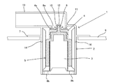
その燃料遮断弁を図15に示す。この燃料遮断弁1は、ケース2によって形成される内部空間3にアッパフロート4及びロアフロート5を収納してなるとともに、その上方には上部開口8aを、その下方には下部開口8bを、その上方の周壁面には横穴14を備え、ケース2の多くの部分は燃料タンク6内に挿入され、ケース2の上方外周壁に水平に形成されるフランジ7を燃料タンク6の上壁面に取り付ける形態で配置される。
The fuel cutoff valve is shown in FIG. The fuel shut-off valve 1 has an
ロアフロート5は、燃料タンク6内の燃料が下部開口8bから内部空間3に侵入すると上動する部材であり、その上面には棒状で且つ小径の第1の弁9を有する。アッパフロート4の上面には、リング状で且つ大径の第2の弁4aを有し、ロアフロート5の上方に上下動可能に取り付けられる。また、アッパフロート4は、その中央部に小径の上端開口12を有し、この小径の上端開口12の下端部には、ロアフロート5の小径の第1の弁9が当接可能な第1の弁座10が形成される。
The
大径の上部開口8aの下端部には第2の弁座11が形成され、燃料タンク6内への給油時等、燃料が下部開口8bから内部空間3に侵入すると、ロアフロート5及びアッパフロート4は共に上動し、ロアフロート5の小径の第1の弁9は、アッパフロート4の第1の弁座10に当接して小径の上端開口12を閉鎖するとともに、アッパフロート4の第2の弁4aは、上部開口8aの下端部に形成される第2の弁座11に当接して大径の上部開口8aを閉鎖し、燃料が上部開口8aの上方の連通路13を介して図示しないキャニスタに流出するのを防止する。
A
第1の弁9及び第2の弁4aの閉弁時、燃料タンク6内の圧力により小径の第1の弁9が第1の弁座10に当接する力は、大径の第2の弁4aが第2の弁座11に当接する力よりかなり小さく、燃料タンク6内の圧力が僅かでも低下すると、ロアフロート5は自重で下動し、小径の第1の弁9と第1の弁座10との当接が外れ、小径の上端開口12及び横穴14を介して燃料タンク6内は大気に連通する。
When the
その結果、燃料タンク6内の圧は下がり、大径の第2の弁4aと第2の弁座11との当接が直ちに外れ、大径の上部開口8aが大気に開放するため、燃料タンク6内の圧力は急激に低下する。また、燃料タンク6内の燃料が満タン時、例え、下部開口8bが燃料により塞がれていたとしても、ケース2の側壁面には横穴14が設けられているため、燃料タンク6内で発生する燃料蒸発ガスは横穴14より連通路13方向に流れるため、燃料タンク6内の圧力が過度に高くなることはない。
As a result, the pressure in the
このように、従来の燃料遮断弁1は、満タン制御弁及び燃料漏れ防止弁のそれぞれの機能を併せ持ち、1つのバルブで済むため、コスト面及び利便性において優れている(特許文献1参照)。 Thus, the conventional fuel shut-off valve 1 has both functions of a full tank control valve and a fuel leakage prevention valve, and only one valve is required, so that it is excellent in cost and convenience (see Patent Document 1). .
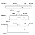
ところで、燃料遮断弁は、燃料タンク内を適正に通気し、例え燃料タンクが傾斜したとしても燃料タンク内の燃料をできるだけ流出しなく、給油満タン時には、燃料タンク内に常にほぼ同量の燃料を給油することができるものが求められる一方、近年いろいろな形状の燃料タンク、例えば、満タン時に、燃料蒸発量が比較的多く、空気層の容積が比較的大きく、傾斜時に燃料遮断弁が液没し易いようなタンク(例えば、図14(A)に示すような扁平タンク)、または、満タン時に、燃料蒸発量が比較的少なく、空気層の容積が比較的小さく、傾斜時に燃料遮断弁が液没し易いようなタンク(例えば、図14(B)に示すような鞍型タンク)、または、満タン時に、燃料蒸発量が比較的多く、空気層の容積が比較的大きく、傾斜時に燃料遮断弁が液切れし易いようなタンク(例えば、図14(C)に示すような大容量タンク)が自動車に採用されるようになり、それに伴い、各タンクで特に、以下の(1)〜(6)のような問題が発生し易くなる。 By the way, the fuel shut-off valve vents properly through the fuel tank, and even if the fuel tank is inclined, the fuel in the fuel tank does not flow out as much as possible. In recent years, fuel tanks of various shapes, for example, when the tank is full, the amount of fuel evaporation is relatively large, the volume of the air layer is relatively large, and the fuel shut-off valve is liquid when tilted. A tank that is easily submerged (for example, a flat tank as shown in FIG. 14A), or when the tank is full, the amount of fuel evaporation is relatively small, the volume of the air layer is relatively small, and the fuel cutoff valve is tilted. Is easily submerged (for example, vertical tank as shown in FIG. 14B), or when the tank is full, the amount of fuel evaporation is relatively large, the volume of the air layer is relatively large, and the tank is inclined. Fuel shut off A tank (for example, a large-capacity tank as shown in FIG. 14C) is easily adopted in an automobile, and accordingly, in each tank, the following (1) to (6) ) Is likely to occur.
(1)給油後の満タン時、特に、燃料タンク内で燃料と空気層との接触面積が大きい扁平タンク及び大容量タンクのような場合、燃料蒸発ガスが多く、燃料遮断弁のケース内外の圧力差が大きくなりケース内に燃料が浸入し、弁を閉鎖して通気を不能にする問題が発生し易くなる(以下、「満タン時の通気不能の問題」という。)(上記扁平タンク及び大容量タンクで、横穴の開口面積が小さいと問題が顕著)。 (1) When the tank is full after refueling, especially in the case of flat tanks and large-capacity tanks where the contact area between the fuel and the air layer is large in the fuel tank, the amount of fuel evaporating gas is large, The pressure difference becomes large, fuel enters the case, and the problem of making the ventilation impossible by closing the valve is likely to occur (hereinafter referred to as “the problem of inability to vent when full”) (the flat tank and The problem is remarkable when the opening area of the horizontal hole is small in a large capacity tank).
(2)燃料タンクは、満タン時の燃料漏れの確認のため傾斜を繰り返す実験が行われる。その傾斜繰り返し時、特に、燃料遮断弁の下端部が常に液没し易い扁平タンク及び鞍型タンクの場合、ケース内に浸入した燃料によりロアフロートが揺れ、ロアフレート上の第1の弁が開放する場合があり、第1の弁が開放するとロアフロートとアッパフロートとの間に溜まった燃料がアッパフロート上方の小径の第3開口から排出する問題が発生し易くなる(以下、「傾斜繰り返し時の燃料漏れ1の問題」という。)(通常、ロアフロートとアッパフロートとの間の近傍に横穴が設けられており、横穴の開口面積が大きいとこの横穴より溜まった燃料がケース外に流出するが、上記扁平タンク及び鞍型タンクで、横穴の開口面積が小さいと問題が顕著)。 (2) The fuel tank is repeatedly tilted to confirm fuel leakage when the tank is full. When the inclination is repeated, particularly in the case of flat tanks and saddle tanks where the lower end of the fuel shut-off valve is always liable to be submerged, the lower float shakes due to the fuel that has entered the case, and the first valve on the lower freight opens. When the first valve is opened, there is a tendency that the fuel accumulated between the lower float and the upper float is discharged from the third opening having a small diameter above the upper float. (It is called “Problem of fuel leakage 1”.) (Normally, a horizontal hole is provided between the lower float and the upper float, and if the opening area of the horizontal hole is large, the fuel accumulated in the horizontal hole flows out of the case. In the above flat tank and vertical tank, the problem is remarkable when the opening area of the horizontal hole is small).
(3)上記傾斜繰り返し時、特に、燃料遮断弁の下端部が液切れし易い大容量タンクの場合、ケース内の燃料が下方に流出する前にアッパフロート上部の第2の弁が開放する場合があり、ケース内の燃料が上方の大径の第2開口から排出する問題が発生し易くなる(以下、「傾斜繰り返し時の燃料漏れ2の問題」という。)(上記大容量タンクで、横穴の開口面積が大きいとケース内外の圧力差がより早く低下するため問題が顕著)。
(3) When the inclination repeats, especially when the lower end of the fuel shut-off valve is a large-capacity tank that is liable to run out of liquid, the second valve above the upper float opens before the fuel in the case flows downward And the problem that the fuel in the case is discharged from the upper large-diameter second opening is more likely to occur (hereinafter referred to as “the problem of
(4)給油時、燃料遮断弁の下端部まで燃料が給油されると、以後は燃料タンク上部の空気層の圧力が高まり、燃料はケース内に浸入し、フロートを押し上げ、弁を閉鎖することになる。特に、空気層の容積が大きい扁平タンク及び大容量タンクのような場合、横穴の開口面積が大きいと燃料遮断弁の下端部まで給油されたとしても、燃料タンク上部の空気層の圧力が上がりにくくなって下端部より高い位置まで燃料が給油されるようになり、満タン時の燃料液面の高さがばらつく問題が発生し易くなる(以下、「給油満タン時の液面位置の問題」という。)(上記扁平タンク及び大容量タンクで、横穴の開口面積が必要以上に大きいと問題が顕著)。 (4) When fuel is supplied to the lower end of the fuel shut-off valve at the time of refueling, the pressure of the air layer above the fuel tank increases thereafter, the fuel enters the case, pushes up the float, and closes the valve become. In particular, in flat tanks and large-capacity tanks where the volume of the air layer is large, if the opening area of the side hole is large, even if fuel is supplied to the lower end of the fuel shut-off valve, the pressure of the air layer above the fuel tank is difficult to increase. The fuel will be refueled to a position higher than the lower end, and it will be easy for problems to occur when the fuel level is full when the tank is full (hereinafter referred to as "the problem of the liquid level when the fuel is full"). (In the above-mentioned flat tank and large-capacity tank, if the opening area of the side hole is larger than necessary, the problem is remarkable).
(5)給油時、満タンになると給油は自動的に止まるが、有人の給油所では係りの人がよく満タン直後に続いて追加給油を行うことがある。満タン直後は、先ずロアフロートが自重で下がり、アッパフロート上部の小径の第3開口が横穴を介してケース外の燃料タンク内の空気層に連通し、空気層の圧力が下がり、ケース内の燃料とともにアッパフロートを含めフロート全体が下がり、上方の大径の第2開口を開放することになる。そのため、ロアフロートが下がった時点直後で、横穴の開口面積が大きいと、ケース内の燃料の流下が早くなり、より多くの追加給油が可能になる。その結果、満タン時の液面の高さが高くなるという問題が発生し易くなる(以下、「満タン直後の追加給油による液面位置の問題」という。)(全てのタンクで、横穴の開口面積が必要以上に大きいと問題が顕著)。 (5) When the tank is full, refueling automatically stops. However, at a manned gas station, the person involved often often performs additional refueling immediately after the tank is full. Immediately after the tank is full, the lower float first falls by its own weight, and the third small opening at the top of the upper float communicates with the air layer in the fuel tank outside the case through the lateral hole, the pressure in the air layer decreases, The entire float including the upper float is lowered together with the fuel, and the upper large-diameter second opening is opened. Therefore, immediately after the lower float is lowered, if the opening area of the side hole is large, the fuel in the case flows down quickly, and more additional fuel can be supplied. As a result, the problem that the level of the liquid level becomes high when the tank is full is likely to occur (hereinafter referred to as “the problem of the liquid level position due to additional refueling immediately after full tank”). The problem is noticeable if the opening area is larger than necessary).
(6)給油時、満タンになると給油は自動的に止まるが、有人の給油所では係りの人がよく満タン後しばらくして追加給油を行うことがある。満タン後しばらくするとロアフロートもアッパフロートも下がった状態になる。このような状態で追加給油する場合、横穴の開口面積が大きいと、空気層の圧力が上がりにくくなり、より多くの追加給油が可能になる。その結果、上記(5)と同様に満タン時の液面の高さが高くなるという問題が発生し易くなる(以下、「満タン後しばらくしてからの追加給油による液面位置の問題」という。)(全てのタンクで、横穴の開口面積が必要以上に大きいと問題が顕著)。 (6) When refueling, when the tank is full, refueling automatically stops. However, at a manned refueling station, the person involved often often performs additional refueling sometime after the tank is full. After a short time after the tank is full, both the lower float and the upper float are lowered. When additional oil is supplied in such a state, if the opening area of the horizontal hole is large, the pressure of the air layer is difficult to increase, and more additional oil can be supplied. As a result, similarly to the above (5), the problem that the liquid level becomes high when the tank is full is likely to occur (hereinafter, “the problem of the liquid surface position due to additional refueling after a full tank”). (In all tanks, the problem is significant when the opening area of the side holes is larger than necessary.)
ところが、従来のケースの側壁面に設けられる横穴は、その開口面積があらかじめ決められており、上記のような問題を各種形状の燃料タンクが求める要求に対し適切に対応することはできなかった。
本願発明の目的は、各種形状の燃料タンクが求める要求に対し適切に対応することができる燃料遮断弁を提供することである。 An object of the present invention is to provide a fuel shut-off valve that can appropriately meet the demands of various types of fuel tanks.
上記目的を達成するため、本願発明は以下の構成を採用する。 In order to achieve the above object, the present invention adopts the following configuration.
請求項1に係る発明では、燃料タンク内に連通する下方の第1開口とキャニスタに連通する上方の第2開口を有するとともに、側方に横穴を有するケースと、前記ケース内の空間に上下動自在に設けられ、上方に第1の弁を有するロアフロートと、前記ロアフロートの上部に上下動自在に設けられ、第2の弁とキャニスタに連通する第3開口を有するアッパフロートと、前記第1の弁が当接することにより前記第3開口が閉鎖される前記アッパフロートに設けられる第1の弁座と、前記第2の弁が当接することにより前記第2開口が閉鎖される前記第2開口近傍に設けられる第2の弁座と、を有し、前記ロアフロートまたは前記アッパフロートに連動し、前記横穴を開閉する弁部材を設け、前記弁部材は、前記ロアフロートまたは前記アッパフロートの位置に応じて前記横穴を開閉し、前記横穴閉鎖時、前記横穴の開口面積を前記横穴開放時に比べ小さくすることを特徴とする。 According to the first aspect of the present invention, there is provided a case having a lower first opening communicating with the fuel tank and an upper second opening communicating with the canister, and having a lateral hole on the side, and a space in the case. A lower float that is freely provided and has a first valve on the upper side, an upper float that is provided on the upper part of the lower float so as to be movable up and down, and has a third opening that communicates with the second valve and the canister; A first valve seat provided in the upper float that closes the third opening when the first valve abuts, and the second opening that is closed when the second valve abuts. A second valve seat provided in the vicinity of the opening, and provided with a valve member that opens and closes the lateral hole in conjunction with the lower float or the upper float, and the valve member includes the lower float or the upper float To open and close said lateral hole according to the position of the funnel, when the lateral hole closed, characterized by small compared with the opening area of the lateral hole at the lateral hole opening.
請求項2に係る発明では、前記弁部材は、前記第1の弁が開で、前記第2の弁が閉のときのみ、前記横穴を閉鎖することを特徴とする。
The invention according to
請求項3に係る発明では、前記弁部材は、さらに前記第1の弁が開で、前記第2の弁が開のとき、前記横穴を閉鎖することを特徴とする。
The invention according to
請求項4に係る発明では、前記弁部材は、さらに前記第1の弁が閉で、前記第2の弁が閉のとき、前記横穴を閉鎖することを特徴とする。
The invention according to
請求項5に係る発明では、前記弁部材は、前記ロアフロートに一体に設けられることを特徴とする。
The invention according to
請求項6に係る発明では、前記弁部材は、前記アッパフロートに一体に設けられることを特徴とする。
The invention according to
請求項7に係る発明では、前記弁部材は、前記横穴に対向する位置に凹みを有することを特徴とする。
In the invention which concerns on
請求項1に係る発明では、アッパフロートまたはロアフロートに連動して、横穴を開閉する弁部材を設け、横穴の閉鎖時、横穴の開口面積を横穴開放時に比べ小さくすることにより、特に、満タン時でのアッパフロート閉でロアフロート閉時と、アッパフロート閉でロアフロート開時と、アッパフロート開でロアフロート開時との3つの状態において、各種形状の燃料タンクが求める要求に対し適正に対応することができ、その結果、各種形状の燃料タンクが有するより多くの問題を解決することができる。 In the invention according to claim 1, a valve member that opens and closes the lateral hole is provided in conjunction with the upper float or the lower float, and when the lateral hole is closed, the opening area of the lateral hole is made smaller than when the lateral hole is opened. When the lower float is closed when the upper float is closed, the lower float is closed when the upper float is closed, and the lower float is opened when the upper float is opened and the lower float is opened. As a result, more problems that the fuel tanks of various shapes have can be solved.
請求項2に係る発明では、弁部材を、第1の弁が開で第2の弁が閉のときのみ、横穴を閉鎖することにより、請求項1に係る発明の効果に加え、特に、満タン時に、燃料蒸発量が比較的多く、空気層の容積が比較的大きく、傾斜時に燃料遮断弁が液没し易いようなタンク、例えば、図14(A)に示すような扁平タンクにおいて、上記(5)の「満タン直後の追加給油による液面位置の問題」を解決することができる。
In the invention according to
請求項3に係る発明では、弁部材を、さらに第1の弁が開で第2の弁が開のとき、横穴を閉鎖することにより、請求項2に係る発明の効果に加え、特に、満タン時に、燃料蒸発量が比較的少なく、空気層の容積が比較的小さく、傾斜時に燃料遮断弁が液没し易いようなタンク、例えば、図14(B)に示すような鞍型タンクにおいて、上記(4)の「給油満タン時の液面位置の問題」及び(6)の「満タン後しばらくしてからの追加給油による液面位置の問題」を解決することができる。なお、上記(1)の「満タン時の通気不能の問題」については不利となるが、このようなタンクは燃料蒸発ガス量は少なく、特に問題はない。
In the invention according to
請求項4に係る発明では、弁部材を、さらに第1の弁が閉で第2の弁が閉のとき、横穴を閉鎖することにより、請求項2に係る発明の効果に加え、特に、満タン時に、燃料蒸発量が比較的多く、空気層の容積が比較的大きく、傾斜時に燃料遮断弁が液切れし易いようなタンク、例えば、図14(C)に示すような大容量タンクにおいて、上記(3)の「傾斜繰り返し時の燃料漏れ2の問題」を解決することができる。
In the invention according to
請求項5に係る発明では、弁部材をロアフロートに一体に設けることにより、請求項1乃至4に係る発明の効果に加え、ロアフロートと一体に成形することができるため、部品点数を低減することができる。
In the invention according to
請求項6に係る発明では、弁部材をアッパフロートに一体に設けることにより、請求項1乃至4に係る発明の効果に加え、アッパフロートと一体に成形することができるため、部品点数を低減することができる。
In the invention according to
請求項7に係る発明では、弁部材の横穴に対向する位置に凹みを設けることにより、請求項1乃至6に係る発明の効果に加え、ケース外からケース内へ蒸気等が流入する場合、凹部がないと弁部材の表面にあたって層流状の流れになり、弁部材の閉鎖による蒸気等の遮蔽効果が見込め難くなるが、凹部があると乱流状になり、ケース内に流入する蒸気等の流量を低減することができる。
In the invention according to
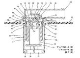
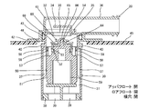
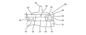
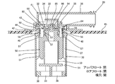
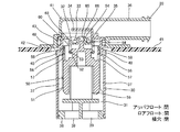
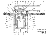
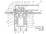
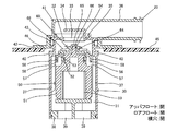
この例のものは、特に、満タン時に、燃料蒸発量が比較的多く、空気層の容積が比較的大きく、傾斜時に燃料遮断弁が液没し易いようなタンク、例えば、図14(A)に示すような扁平タンクにおいて有利なものである。図1にアッパフロートが閉でロアフロートが閉状態時の全体断面図を示し、図2にアッパフロートが閉でロアフロートが開状態時の全体断面図を示し、図3にアッパフロートが開でロアフロートが開状態時の全体断面図を示し、図4にロアフロートの一部拡大正面図を示し、図5にアッパフロートの斜視図を示す。本願発明の燃料遮断弁は、どのような用途に用いられるものでも良いが、以下においては、自動車用のものについて説明する。 In this example, in particular, when the tank is full, the amount of fuel evaporation is relatively large, the volume of the air layer is relatively large, and the fuel shut-off valve is liable to be submerged when inclined, for example, FIG. It is advantageous in a flat tank as shown in FIG. 1 shows an overall cross-sectional view when the upper float is closed and the lower float is closed, FIG. 2 shows an overall cross-sectional view when the upper float is closed and the lower float is open, and FIG. 3 shows an upper float opened. FIG. 4 is a partially enlarged front view of the lower float, and FIG. 5 is a perspective view of the upper float when the lower float is in the open state. The fuel shut-off valve of the present invention may be used for any application, but in the following, a description will be given for an automobile.
燃料遮断弁20は、ケース30、ケース30内に配置されるロアフロート50、アッパフロート60、第1の弁54及び第2の弁68等を有する。
The
ケース30は、下方が開放された円筒状の樹脂製部材であり、内部空間31を有する。ケース30の上壁32の中央には、内部空間31に連通する上部開口である第2開口33を有する。前記上壁32の上面には、第2開口33を覆う断面L字型の遮蔽部材34が立設され、第2開口33から流出する燃料及び燃料蒸発ガス等を衝突させ、更に流出方向と反対側に迂回させ、液状燃料を分離し、且つケース30内に戻す機能を有する。また、前記第2開口33の下端部には、後記の第2の弁68が当接する第2の弁座35が形成される。
The
前記第2開口33には、連通路36が連結される。この連通路36は、図示しないキャニスタに連通されており、燃料タンク45内の燃料蒸発ガスをキャニスタに排出したり、大気を燃料タンク45内に導入する。
A
ケース30内には、内壁面に沿って垂直方向に複数のリブ37が等間隔に設けられており、該リブ37は、ケース30の内壁面とロアフロート50の外周面との間に空間を確保し、燃料蒸発ガス等の通路を形成するとともに、その先端でロアフロート50の上下動を案内する。
In the
ケース30の底部には、熱溶着等の手段により底部材38が取り付けられる。この底部材38には、燃料等が内部空間31に侵入するための複数の底部開口である第1開口39が穿設される。この第1開口39は、給油時或いは自動車が傾斜状態にあったり横転した時等に内部空間31に燃料を侵入させるためのもので、給油時等に内部空間31に侵入する燃料によりロアフロート50及びアッパフロート60を上動させ、アッパフロート60の上部に設けられる後記の第2の弁68により第2開口33を閉鎖し、燃料がキャニスタに流出するのを防止する。
A
また、ケース30の上方の側壁面には、複数個、例えば2個の円形の横穴40がほぼ対向して設けられ、燃料タンク45内の燃料蒸発ガスは、この横穴40より、内部空間31に侵入し、第2開口33及び連通路36を介し図示しないキャニスタに排出される。
In addition, a plurality of, for example, two circular lateral holes 40 are provided on the side wall surface above the
ケース30の上方には、樹脂製のキャップ部材41がシール部材43を介して嵌合されている。このキャップ部材41には、キャニスタに連通する連通路36及び燃料タンク45に取り付けられるフランジ42が一体に形成される。なお、この実施例及び他の実施例についても同様であるが、キャップ部材41はケース30と一体に形成され、全体でケース30を形成していてもよい。
A
燃料タンク45の上壁面には取付孔46が設けられ、この取付孔46内にケース30を挿入し、キャップ部材41のフランジ42を燃料タンク45の上壁面に固定する。その結果、燃料遮断弁20は、図1に示すように燃料タンク45内に挿入される形態で取り付けられる。
A mounting
ケース30内に挿入されるロアフロート50は、樹脂製で下方開放の概略中空円筒形状を呈し、図4にも示すようにその下方には大径円筒部51を、上方には小径円筒部52を有する。大径円筒部51は同径でその外周部は、ケース30の内側面に設けられる垂直なリブ37に沿って上下動する。
The
小径円筒部52の上部外周面には、径方向に張り出した複数個、例えば4個の係止片53がほぼ等間隔に設けられ、更に小径円筒部52の上面中央部には、柱状でその先端が円弧状の第1の弁54が立設される。
A plurality of, for example, four locking
また、前記大径円筒部51の上面外周には、複数の支持片55が一体に立設し、その支持片55の上部には、弁部材56が一体に設けられ、支持片55が設けられない大径円筒部51と弁部材56との間には開放空間57が形成される。
A plurality of
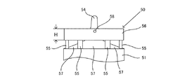
弁部材56は、上下方向の長さhのリング状の部材で、その上端は前記係止片53の直上部まで伸び、その外径は大径円筒部51とほぼ同じにされ、その外周面の前記横穴40と対向する位置には、横穴40より若干大きい円形の凹部58が形成される。そして、弁部材56の外周面は横穴40と例えば、0.5mmの隙間を有して対向し、横穴40の閉鎖時に横穴40の開口面積を閉鎖されない大の状態から小の状態にする。このように横穴40の閉鎖は開口面積が小さくなることである。
The
また、凹部58は、横穴40よりケース30内に浸入する燃料及び蒸気の流れを受け止め、そのエネルギを吸収する。このように弁部材56をリング状にすることにより強度を高めることができる。なお、リング状に変えて円弧状にし、横穴40に対向する位置に設けるようにしてもよい。また、凹部58も燃料の流れを低減できるものであれば、どのような大きさ及び形状であってもよい。また、アッパフロートとロアフロートの各開閉状態にて、アッパフロートとロアフロートの横穴対向位置への凹部の設定の要否は、各状態での必要性により任意とする。
In addition, the
ロアフロート50と底部材38との間には、スプリング59が介在される。スプリング59はそれ自体ではロアフロート50を上動する力はないが、ケース30内に燃料が侵入したとき燃料による浮力とともにロアフロート50を素早く上動する力として作用する。
A
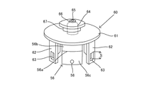
ロアフロート50の小径円筒部52の上方には、アッパフロート60が取り付けられる。アッパフロート60は、樹脂製で、図5に示すように円板状部材61及び脚部材62を有する。脚部材62は、円板状部材61の外周底面に複数個、例えば4個ほぼ等間隔に垂下する断面円弧状の部材で、その下端部近傍には、ロアフロート50の小径円筒部52の外周面に形成される複数個の係止片53が係合される係合溝63が設けられる。
An
アッパフロート60の下面中央部には、ロアフロート50上の小径の第1の弁54が嵌入する凹陥部64を有する。また、アッパフロート60の中央には、凹陥部64にまで達する上下方向に開口した第3開口65を有するとともに、この第3開口65の下端であり前記凹陥部64の上端には第1の弁座66が設けられる。そして、この凹陥部64内にロアフロート50上の第1の弁54が嵌入し、第1の弁座に当接することによりアッパフロート60はロアフロート50の上部にピボット状に支持される。
A central portion of the lower surface of the
アッパフロート60の上部外周側面にはリング状に窪んだ溝部67が形成されるとともに、この溝部67内にはドーナツ状で且つゴム製の第2の弁68が嵌合される。この第2の弁68は、ロアフロート50が上動した時にケース30の上部に形成される第2の弁座35に当接し、燃料等の第2開口33側への流出を防止する。この場合、第2の弁68は前後左右方向にゆとりをもって嵌合され、ロアフロート50が傾斜した状態であっても第2の弁68と第2の弁座35との密着を良好に行う。
A
ロアフロート50とアッパフロート60との組み付けは次のように行われる。まず、アッパフロート60の溝部67内に第2の弁68を嵌合する。次いで、ロアフロート50の上部にアッパフロート60を置き、そのままの状態でアッパフロート60の上部から力を加え、アッパフロート60を下動させる。するとアッパフロート60はロアフロート50の小径円筒部52の外周上に沿って押し込まれ、ついには脚部材62の係合溝63内に、小径円筒部52の外周上に設けられる係止片53が入り込み、両部材は無理ばめ係合される。その結果、アッパフロート60は、ロアフロート50から切り離されることなく、上下動自在に連結される。
The assembly of the
前記係合溝63は、長さSを有し、アッパフロート60が第2の弁座35に当接し第2開口33を閉鎖時、ロアフロート50は長さSだけ下降することができ、その際ロアフロート50の第1の弁54はアッパフロート60の中央部の第3開口65を開口する。
The
まず、弁部材56がない燃料遮断弁20給油満タン時からその後にかけての作用について簡単に説明する。
First, the operation from the time when the fuel shut-off
給油満タン直前等に、燃料が第1開口39から内部空間31に侵入すると、侵入した燃料は、ケース30の内壁面とロアフロート50の側壁面との間の内部空間31を通り、第2開口33を経て連通路36に流れようとする。しかしながら、内部空間31に侵入する燃料は、アッパフロート60及びロアフロート50を共に上方位置(以下、アッパフロート閉でロアフロート閉時という。)に押し上げ、第2開口33を閉鎖して燃料が連通路36に流出するのを防止する。
When the fuel enters the
満タン直後、燃料タンク45内の圧力は高くなっており、第2の弁68は高い圧力を下方から受け第2の弁座35に強い力で当接され、燃料タンク45内の圧力が多少下がったくらいではその当接が外れないが、ロアフロート50はアッパフロート60に対し、第1の弁54と凹陥部64との小さな面積での当接であり、燃料タンク45内の燃料液面が僅かに下がるだけで第1の弁54と凹陥部64との当接が外れ、ロアフロート50は自重で落下しアッパフロート60は上方位置でロアフロート50は長さS(図5参照)だけ下方位置(以下、アッパフロート閉でロアフロート開時という。)に位置する。
Immediately after the tank is full, the pressure in the
満タン直後しばらくすると、アッパフロート60の第3開口65が開放するため、ケース30の内外の圧力差が低下し、アッパフロート60及びロアフロート50は下方位置(以下、アッパフロート開でロアフロート開時という。)になり、燃料タンク45内で発生した燃料蒸発ガスは、横穴40より内部空間31に入り、第2開口33及び連通路36を介してキャニスタに送られるというように、燃料タンク45の通気が行われる。
After a while, the
次に、本願発明の作用について説明する。図1乃至図3は、図14で示すように満タン時の燃料遮断弁20の状態、即ち、底部材38にまで燃料が満たされている状態を示しており、図1は満タン直前の状態(アッパフロート閉でロアフロート閉時)を、図2は満タン直後の状態(アッパフロート閉でロアフロート開時)を、図3は満タン後しばらくしてからの状態(アッパフロート開でロアフロート開時)を示す。
Next, the operation of the present invention will be described. FIGS. 1 to 3 show the state of the fuel shut-off
そして、図1の満タン直前の状態(アッパフロート閉でロアフロート閉時)では、弁部材56は、ほぼ対向位置に設けられる2個の横穴40の上部に位置し、その下方の開放空間57を介して横穴40を直接内部空間31に連通する。
In the state immediately before the full tank in FIG. 1 (when the upper float is closed and the lower float is closed), the
満タン時に、燃料蒸発量が比較的多く、空気層の容積が比較的大きく、傾斜時に燃料遮断弁が液没し易いようなタンク、例えば、図14(A)に示すような扁平タンクにおいては、この時期、上記背景技術の項目で記載した上記(2)の「傾斜繰り返し時の燃料漏れ1の問題」が発生し易いが、横穴40を開放することによりそのような問題の発生を低減することができる。
In a tank in which the fuel evaporation amount is relatively large when the tank is full, the volume of the air layer is relatively large, and the fuel shut-off valve is liable to be submerged when inclined, for example, a flat tank as shown in FIG. At this time, the “problem of fuel leakage 1 at the time of repeated tilting” described in the item of the background art is likely to occur, but the occurrence of such a problem is reduced by opening the
図2の満タン直後の状態(アッパフロート閉でロアフロート開時)では、弁部材56は、横穴40を閉鎖する位置になり、横穴40を閉鎖し、横穴40の開口面積を絞って小さくする。
In the state immediately after the full tank in FIG. 2 (when the upper float is closed and the lower float is opened), the
上記扁平タンクにおいては、この時期、上記背景技術の項目で記載した上記(5)の「満タン直後の追加給油による液面位置の問題」が発生し易いが、横穴40を閉鎖することによりそのような問題の発生を低減することができる。なお、この場合、横穴40には弁部材56の外周に設けた凹部58が対向しており、ケース30外から横穴40を通ってケース内に流れる蒸気が乱流状となり、流入時の圧力抵抗が大きくケース内の液落ちが抑えられ、追加給油を低減できる。
In the flat tank, at this time, the “problem of the liquid surface position due to additional oil supply immediately after full tank” described in the item of the background art is likely to occur. The occurrence of such problems can be reduced. In this case, the
図3の満タン後しばらくしてからの状態(アッパフロート開でロアフロート開時)では、弁部材56の上下方向の長さh(図4参照)はあまり大きく形成されていないため、弁部材56は、横穴40の下部に位置し、横穴40を直接内部空間31に連通する。
In the state after a while after the full tank in FIG. 3 (when the upper float is opened and the lower float is opened), the vertical length h (see FIG. 4) of the
上記扁平タンクにおいては、この時期、上記背景技術の項目で記載した上記(1)の「満タン時の通気不能の問題」、上記(4)の「給油満タン時の液面位置の問題」及び上記(6)の「満タン後しばらくしてからの追加給油による液面位置の問題」が発生し易く、上記(1)の問題を解決するには、横穴40を開放する必要があり、上記(4)及び上記(6)の問題を解決するには、横穴40を閉鎖する必要がある。しかし、この時期上記扁平タンクでは、上記(1)の問題がより重要になるため、上記(1)の問題の解決を他のものより優先させる。即ち、横穴40開放することにより上記(1)の問題の発生を低減することができる。
In the above-described flat tank, at this time, the above-mentioned (1) “Problem of inability to vent when full tank” described in the section of the background art, and “(Problem of liquid level position when full of fuel supply)” described in (4) above. And the above-mentioned (6) “problem of liquid level position due to additional refueling after a while after full” is likely to occur, and in order to solve the problem (1), it is necessary to open the
この例のものは、特に、満タン時に、燃料蒸発量が比較的少なく、空気層の容積が比較的小さく、傾斜時に燃料遮断弁が液没し易いようなタンク、例えば、図14(B)に示すような鞍型タンクにおいて有利なものである。この例のものは、実施例1のものと同様に弁部材をロアフロート上に設けるが、実施例1との相違は、その弁部材の上下方向の長さを図9に示すように実施例1の長さhより長い長さHにするものである。なお、実施例1と共通のものの説明は省略し、主として異なるものについて説明する。 This example is a tank in which the amount of fuel evaporation is relatively small when the tank is full, the volume of the air layer is relatively small, and the fuel shut-off valve is liable to be submerged when inclined, for example, FIG. This is advantageous in a vertical tank as shown in FIG. In this example, the valve member is provided on the lower float as in the first embodiment. The difference from the first embodiment is that the length of the valve member in the vertical direction is as shown in FIG. The length H is longer than the length h of 1. In addition, the description of what is common to the first embodiment is omitted, and mainly the difference is described.
図6にアッパフロートが閉でロアフロートが閉状態時の全体断面図を示し、図7にアッパフロートが閉でロアフロートが開状態時の全体断面図を示し、図8にアッパフロートが開でロアフロートが開状態時の全体断面図を示し、図9にロアフロートの一部拡大正面図を示す。 6 is an overall cross-sectional view when the upper float is closed and the lower float is closed, FIG. 7 is an overall cross-sectional view when the upper float is closed and the lower float is open, and FIG. 8 is an open view of the upper float. FIG. 9 shows a partially enlarged front view of the lower float when the lower float is in an open state.
その作用について説明する。弁部材56は実施例1のものより長い長さHであり、図6の満タン直前の状態(アッパフロート閉でロアフロート閉時)では、弁部材56の下方外周は、ほぼ対向位置に設けられる2個の横穴40の上部に位置し、その下方の開放空間57を介して横穴40を直接内部空間31に連通する。
The operation will be described. The
満タン時に、燃料蒸発量が比較的少なく、空気層の容積が比較的小さく、傾斜時に燃料遮断弁が液没し易いようなタンク、例えば、図14(B)に示すような鞍型タンクにおいては、この時期、上記背景技術の項目で記載した上記(2)の「傾斜繰り返し時の燃料漏れ1の問題」が発生し易いが、横穴40を開放することによりそのような問題の発生を低減することができる。
In a tank in which the fuel evaporation amount is relatively small when the tank is full, the volume of the air layer is relatively small, and the fuel shut-off valve is liable to be submerged when inclined, for example, a vertical tank as shown in FIG. At this time, the “problem of fuel leakage 1 at the time of repeated tilting” described in the item of the background art is likely to occur at this time, but the occurrence of such a problem is reduced by opening the
図7の満タン直後の状態(アッパフロート閉でロアフロート開時)では、弁部材56は、横穴40を閉鎖する位置になり、横穴40を閉鎖し、横穴40の開口面積を絞って小さくする。
In the state immediately after the full tank in FIG. 7 (when the upper float is closed and the lower float is opened), the
上記鞍型タンクにおいては、この時期、上記背景技術の項目で記載した上記(5)の「満タン直後の追加給油による液面位置の問題」が発生し易いが、横穴40を閉鎖することによりそのような問題の発生を低減することができる。
In the vertical tank, at this time, the “problem of the liquid level due to the additional oil supply immediately after full tank” described in the item of the background art is likely to occur, but by closing the
図8の満タン後しばらくしてからの状態(アッパフロート開でロアフロート開時)では、弁部材56の上下方向の長さH(図9参照)は長いため、弁部材56は、横穴40を閉鎖し、横穴40の開口面積を絞って小さくする。
In the state after a while after the full tank in FIG. 8 (when the upper float is opened and the lower float is opened), the
上記鞍型タンクにおいては、この時期、上記背景技術の項目で記載した上記(1)の「満タン時の通気不能の問題」、上記(4)の「給油満タン時の液面位置の問題」及び上記(6)の「満タン後しばらくしてからの追加給油による液面位置の問題」が発生し易く、上記(1)の問題を解決するには、横穴40を開放する必要があり、上記(4)及び上記(6)の問題を解決するには、横穴40を閉鎖する必要がある。しかし、この時期上記鞍型タンクでは、上記(1)の問題は比較的少ないため、上記(4)及び上記(6)の問題の解決を上記(1)のものに優先させる。即ち、横穴40閉鎖することにより上記(4)及び上記(6)の問題の発生を低減することができる。
In the vertical tank, at this time, the “problem of inability to vent when full” described in the item of the background art, and the “problem of liquid level when full of fuel” described in (4) above. And the above-mentioned (6) “problem of liquid level position due to additional refueling after a while after full tank” is likely to occur, and in order to solve the problem (1), it is necessary to open the
なお、この場合、横穴40には弁部材56の上方外周に設けた凹部58が対向しており、ケース30外から横穴40を通ってケース内に流れる蒸気が乱流状となり、流入時の圧力抵抗が大きくケース内の液落ちが抑えられ、追加給油を低減できる。この例の場合、弁部材56の外周に沿って上下方向に長い凹部58を形成しておくと、図8の状態で燃料流がケース30内に侵入することが考えられるため、弁部材56の下方外周には設けていないが、上下方向に長い凹部58としてもよいし、上下2箇所としてもよい。
In this case, the
この例のものは、特に、満タン時に、燃料蒸発量が比較的多く、空気層の容積が比較的大きく、傾斜時に燃料遮断弁が液切れし易いようなタンク、例えば、図14(C)に示すような大容量タンクにおいて有利なものである。この例のものは、弁部材をアッパフロート上に設ける点で異なるが、その他の点では共通する。実施例1と共通のものの説明は省略し、主として異なるものについて説明する。 In this example, in particular, when the tank is full, the fuel evaporation amount is relatively large, the air layer volume is relatively large, and the fuel shut-off valve is liable to run out when the tank is inclined, for example, FIG. It is advantageous in a large capacity tank as shown in FIG. This example differs in that the valve member is provided on the upper float, but is common in other points. Descriptions common to those in the first embodiment will be omitted, and mainly the differences will be described.
図10にアッパフロートが閉でロアフロートが閉状態時の全体断面図を示し、図11にアッパフロートが閉でロアフロートが開状態時の全体断面図を示し、図12にアッパフロートが開でロアフロートが開状態時の全体断面図を示し、図13にアッパフロートの斜視図を示す。 FIG. 10 is an overall cross-sectional view when the upper float is closed and the lower float is closed, FIG. 11 is an overall cross-sectional view when the upper float is closed and the lower float is open, and FIG. 12 is an open view of the upper float. FIG. 13 is a perspective view of the upper float when the lower float is in an open state.
アッパフロート60の円板状部材61は、実施例1、2のものより大径にされ、その外周端には、断面円弧状で正面視矩形状の弁部材56が垂下する。この弁部材56は、横穴40に対向する位置に設けられ、上から略1/3のところに水平の段部56aが形成され、段部56aの上方には小径部56bが、下方にはロアフロート50の大径円筒部51と同じ径の大径部56cが形成される。大径部56cは横穴40に対向する部分であり、対向箇所である下方外周には凹部58が形成される。なお、弁部材56は実施例1、2のようなリング状であってもよい。
The disk-shaped
その作用について説明する。図10の満タン直前の状態(アッパフロート閉でロアフロート閉時)では、弁部材56の下方外周は、ほぼ対向位置に設けられる2個の横穴40を閉鎖するように位置する。なお、この場合、横穴40には弁部材56の下方外周に設けた凹部58が対向しており、ケース30外から横穴40を通ってケース内に流れる蒸気が乱流状となり、流入時の圧力抵抗が大きくケース内の液落ちが抑えられ、追加給油を低減できる。
The operation will be described. In the state immediately before the full tank in FIG. 10 (when the upper float is closed and the lower float is closed), the lower outer periphery of the
満タン時に、燃料蒸発量が比較的多く、空気層の容積が比較的大きく、傾斜時に燃料遮断弁が液切れし易いようなタンク、例えば、図14(C)に示すような大容量タンクにおいては、この時期、上記背景技術の項目で記載した上記(3)の「傾斜繰り返し時の燃料漏れ2の問題」が発生し易いが、横穴40を閉鎖することによりそのような問題の発生を低減することができる。
In a tank where the fuel evaporation amount is relatively large when the tank is full, the volume of the air layer is relatively large, and the fuel shut-off valve is liable to run out when the tank is inclined, such as a large capacity tank as shown in FIG. At this time, the “problem of
図11の満タン直後の状態(アッパフロート閉でロアフロート開時)では、弁部材56は、依然として横穴40を閉鎖し、横穴40の開口面積を絞って小さくする。
In the state immediately after the full tank in FIG. 11 (when the upper float is closed and the lower float is opened), the
上記大容量タンクにおいては、この時期、上記背景技術の項目で記載した上記(5)の「満タン直後の追加給油による液面位置の問題」が発生し易いが、横穴40を閉鎖することによりそのような問題の発生を低減することができる。
In the large-capacity tank, at this time, the “problem of the liquid surface position due to additional oil supply immediately after full tank” described in the item of the background art is likely to occur. However, by closing the
図12の満タン後しばらくしてからの状態(アッパフロート開でロアフロート開時)では、弁部材56の上方の小径部56bが位置し、弁部材56は横穴40を開放する。
In a state after a while after the full tank shown in FIG. 12 (when the upper float is opened and the lower float is opened), the small-
上記大容量タンクにおいては、この時期、上記背景技術の項目で記載した上記(1)の「満タン時の通気不能の問題」、上記(4)の「給油満タン時の液面位置の問題」及び上記(6)の「満タン後しばらくしてからの追加給油による液面位置の問題」が発生し易く、上記(1)の問題を解決するには、横穴40を開放する必要があり、上記(4)及び上記(6)の問題を解決するには、横穴40を閉鎖する必要がある。しかし、この時期上記大容量タンクでは、上記(1)の問題がより重要になるため、上記(1)の問題の解決を他のものより優先させる。即ち、横穴40開放することにより上記(1)の問題の発生を低減することができる。
In the above-mentioned large-capacity tank, at this time, the above-mentioned (1) “Problem of inability to vent when full” described in the section of the background art, and “4. And the above-mentioned (6) “problem of liquid level position due to additional refueling after a while after full tank” is likely to occur, and in order to solve the problem (1), it is necessary to open the
なお、前記実施例の構成に限定されるものではなく、発明の要旨を逸脱しない範囲において適宜設計変更可能である。例えば、上記各実施例では、特有な形状の燃料タンクを用いて説明しているが、そのようなタンクに特定されず、各燃料タンクでどの状態を優先させるかで横穴の開放及び閉鎖時期は適宜可変可能である。 It should be noted that the present invention is not limited to the configuration of the above-described embodiment, and the design can be changed as appropriate without departing from the gist of the invention. For example, in each of the above embodiments, a fuel tank having a specific shape has been described. However, it is not specified as such a tank, and the opening and closing timing of the side hole depends on which state is prioritized in each fuel tank. It can be changed appropriately.
20 燃料遮断弁 30 ケース
31 内部空間 32 上壁
33 第2開口 34 遮蔽部材
35 第2の弁座 36 連通路
37 リブ 38 底部材
39 第1開口 40 横穴
41 キャップ部材 42 フランジ
43 シール部材 45 燃料タンク
46 取付孔 50 ロアフロート
51 大径円筒部 52 小径円筒部
53 係止片 54 第1の弁
55 支持片 56 弁部材
56a 段部 56b 小径部
56c 大径部 57 開放空間
58 凹部 59 スプリング
60 アッパフロート 61 円板状部材
62 脚部材 63 係合溝
64 凹陥部 65 第3開口
66 第1の弁座 67 溝部
68 第2の弁
DESCRIPTION OF
Claims (7)
前記ケース内の空間に上下動自在に設けられ、上方に第1の弁を有するロアフロートと、
前記ロアフロートの上部に上下動自在に設けられ、第2の弁とキャニスタに連通する第3開口を有するアッパフロートと、
前記第1の弁が当接することにより前記第3開口が閉鎖される前記アッパフロートに設けられる第1の弁座と、
前記第2の弁が当接することにより前記第2開口が閉鎖される前記第2開口近傍に設けられる第2の弁座と、を有し、
前記ロアフロートまたは前記アッパフロートに連動し、前記横穴を開閉する弁部材を設け、
前記弁部材は、前記ロアフロートまたは前記アッパフロートの位置に応じて前記横穴を開閉し、前記横穴閉鎖時、前記横穴の開口面積を前記横穴開放時に比べ小さくすることを特徴とする燃料遮断弁。 A case having a lower first opening communicating with the fuel tank and an upper second opening communicating with the canister, and having a lateral hole on the side;
A lower float provided in the space in the case so as to be movable up and down, and having a first valve above;
An upper float provided on the upper part of the lower float so as to be movable up and down and having a third opening communicating with the second valve and the canister;
A first valve seat provided in the upper float in which the third opening is closed by the contact of the first valve;
A second valve seat provided in the vicinity of the second opening, wherein the second opening is closed when the second valve abuts,
In conjunction with the lower float or the upper float, a valve member for opening and closing the side hole is provided,
The fuel shut-off valve, wherein the valve member opens and closes the lateral hole according to the position of the lower float or the upper float, and when the lateral hole is closed, the opening area of the lateral hole is smaller than that when the lateral hole is opened.
Priority Applications (1)
| Application Number | Priority Date | Filing Date | Title |
|---|---|---|---|
| JP2008324929A JP2010143498A (en) | 2008-12-22 | 2008-12-22 | Fuel shut-off valve |
Applications Claiming Priority (1)
| Application Number | Priority Date | Filing Date | Title |
|---|---|---|---|
| JP2008324929A JP2010143498A (en) | 2008-12-22 | 2008-12-22 | Fuel shut-off valve |
Publications (1)
| Publication Number | Publication Date |
|---|---|
| JP2010143498A true JP2010143498A (en) | 2010-07-01 |
Family
ID=42564366
Family Applications (1)
| Application Number | Title | Priority Date | Filing Date |
|---|---|---|---|
| JP2008324929A Pending JP2010143498A (en) | 2008-12-22 | 2008-12-22 | Fuel shut-off valve |
Country Status (1)
| Country | Link |
|---|---|
| JP (1) | JP2010143498A (en) |
Cited By (8)
| Publication number | Priority date | Publication date | Assignee | Title |
|---|---|---|---|---|
| JP2010188991A (en) * | 2009-01-23 | 2010-09-02 | Yachiyo Industry Co Ltd | Vent regulation valve device |
| WO2012137774A1 (en) * | 2011-04-04 | 2012-10-11 | 株式会社ニフコ | Connector for fuel tank |
| JP2013028213A (en) * | 2011-07-27 | 2013-02-07 | Toyoda Gosei Co Ltd | Fuel shutoff valve |
| WO2013039013A1 (en) * | 2011-09-12 | 2013-03-21 | 株式会社ニフコ | Fuel tank connector |
| JP2013203279A (en) * | 2012-03-29 | 2013-10-07 | Toyoda Gosei Co Ltd | Fuel shut-off valve |
| WO2018168712A1 (en) * | 2017-03-16 | 2018-09-20 | 株式会社パイオラックス | Fuel tank valve device |
| CN110345289A (en) * | 2018-04-05 | 2019-10-18 | 百乐仕株式会社 | Valve gear |
| JP7553365B2 (en) | 2021-01-20 | 2024-09-18 | 株式会社ニフコ | Valve mechanism |
-
2008
- 2008-12-22 JP JP2008324929A patent/JP2010143498A/en active Pending
Cited By (17)
| Publication number | Priority date | Publication date | Assignee | Title |
|---|---|---|---|---|
| JP2010188991A (en) * | 2009-01-23 | 2010-09-02 | Yachiyo Industry Co Ltd | Vent regulation valve device |
| WO2012137774A1 (en) * | 2011-04-04 | 2012-10-11 | 株式会社ニフコ | Connector for fuel tank |
| US9493065B2 (en) | 2011-04-04 | 2016-11-15 | Nifco Inc. | Connector for fuel tank |
| JP2013028213A (en) * | 2011-07-27 | 2013-02-07 | Toyoda Gosei Co Ltd | Fuel shutoff valve |
| JP2013060033A (en) * | 2011-09-12 | 2013-04-04 | Nifco Inc | Fuel tank connector |
| CN103764426A (en) * | 2011-09-12 | 2014-04-30 | 株式会社利富高 | Fuel tank connector |
| EP2756978A4 (en) * | 2011-09-12 | 2015-08-12 | Nifco Inc | Fuel tank connector |
| WO2013039013A1 (en) * | 2011-09-12 | 2013-03-21 | 株式会社ニフコ | Fuel tank connector |
| US9586475B2 (en) | 2011-09-12 | 2017-03-07 | Nifco Inc. | Fuel tank connector |
| JP2013203279A (en) * | 2012-03-29 | 2013-10-07 | Toyoda Gosei Co Ltd | Fuel shut-off valve |
| WO2018168712A1 (en) * | 2017-03-16 | 2018-09-20 | 株式会社パイオラックス | Fuel tank valve device |
| JPWO2018168712A1 (en) * | 2017-03-16 | 2019-12-12 | 株式会社パイオラックス | Valve device for fuel tank |
| US11135913B2 (en) | 2017-03-16 | 2021-10-05 | Piolax, Inc. | Fuel tank valve device |
| CN110345289A (en) * | 2018-04-05 | 2019-10-18 | 百乐仕株式会社 | Valve gear |
| JP2019183707A (en) * | 2018-04-05 | 2019-10-24 | 株式会社パイオラックス | Valve gear |
| JP7115890B2 (en) | 2018-04-05 | 2022-08-09 | 株式会社パイオラックス | valve device |
| JP7553365B2 (en) | 2021-01-20 | 2024-09-18 | 株式会社ニフコ | Valve mechanism |
Similar Documents
| Publication | Publication Date | Title |
|---|---|---|
| JP2010143498A (en) | Fuel shut-off valve | |
| JP4534841B2 (en) | Fuel shut-off valve | |
| JP5874601B2 (en) | Fuel shut-off valve | |
| JP2011201535A (en) | Dual function valve for fuel tank | |
| US8490603B2 (en) | Fuel tank valve device and fuel tank ventilation device | |
| US20090211649A1 (en) | Fuel cutoff valve | |
| JP3909837B2 (en) | Fuel tank fuel spill regulating device | |
| JP2004257264A (en) | Full tank control valve structure | |
| JP5370270B2 (en) | Fuel shut-off valve | |
| JP4237042B2 (en) | Evaporative gas control valve structure | |
| JP2015150935A (en) | valve device | |
| JP2010105469A (en) | Fuel shut-off valve | |
| US7448364B2 (en) | Fuel cutoff valve and breather pipe | |
| JP2009286201A (en) | Venting device for fuel tank | |
| US20110017320A1 (en) | Fuel Cutoff valve | |
| JP2011102098A (en) | Fuel shut-off valve | |
| JP2005138677A (en) | Full tank detection valve | |
| JP2004353518A (en) | Tank fill-up regulation valve | |
| JP5461087B2 (en) | Fuel shut-off valve | |
| JP4131399B2 (en) | Fuel tank fuel spill regulating device | |
| JP5123816B2 (en) | Float valve device | |
| WO2012118118A1 (en) | Fuel shutoff valve | |
| JP2006177164A (en) | Fill-up regulating valve | |
| JP2010173397A (en) | Fuel shutoff valve | |
| JP2010105468A (en) | Fuel shut-off valve |
