WO2022080110A1 - ロータ及び回転電機 - Google Patents
ロータ及び回転電機 Download PDFInfo
- Publication number
- WO2022080110A1 WO2022080110A1 PCT/JP2021/034893 JP2021034893W WO2022080110A1 WO 2022080110 A1 WO2022080110 A1 WO 2022080110A1 JP 2021034893 W JP2021034893 W JP 2021034893W WO 2022080110 A1 WO2022080110 A1 WO 2022080110A1
- Authority
- WO
- WIPO (PCT)
- Prior art keywords
- rotor
- permanent magnet
- rotor core
- magnet
- axial end
- Prior art date
- Legal status (The legal status is an assumption and is not a legal conclusion. Google has not performed a legal analysis and makes no representation as to the accuracy of the status listed.)
- Ceased
Links
Images










Classifications
-
- H—ELECTRICITY
- H02—GENERATION; CONVERSION OR DISTRIBUTION OF ELECTRIC POWER
- H02K—DYNAMO-ELECTRIC MACHINES
- H02K1/00—Details of the magnetic circuit
- H02K1/06—Details of the magnetic circuit characterised by the shape, form or construction
- H02K1/22—Rotating parts of the magnetic circuit
- H02K1/27—Rotor cores with permanent magnets
- H02K1/2706—Inner rotors
- H02K1/272—Inner rotors the magnetisation axis of the magnets being perpendicular to the rotor axis
- H02K1/274—Inner rotors the magnetisation axis of the magnets being perpendicular to the rotor axis the rotor consisting of two or more circumferentially positioned magnets
- H02K1/2753—Inner rotors the magnetisation axis of the magnets being perpendicular to the rotor axis the rotor consisting of two or more circumferentially positioned magnets the rotor consisting of magnets or groups of magnets arranged with alternating polarity
- H02K1/276—Magnets embedded in the magnetic core, e.g. interior permanent magnets [IPM]
- H02K1/2766—Magnets embedded in the magnetic core, e.g. interior permanent magnets [IPM] having a flux concentration effect
-
- H—ELECTRICITY
- H02—GENERATION; CONVERSION OR DISTRIBUTION OF ELECTRIC POWER
- H02K—DYNAMO-ELECTRIC MACHINES
- H02K1/00—Details of the magnetic circuit
- H02K1/06—Details of the magnetic circuit characterised by the shape, form or construction
- H02K1/22—Rotating parts of the magnetic circuit
- H02K1/27—Rotor cores with permanent magnets
- H02K1/2706—Inner rotors
- H02K1/272—Inner rotors the magnetisation axis of the magnets being perpendicular to the rotor axis
- H02K1/274—Inner rotors the magnetisation axis of the magnets being perpendicular to the rotor axis the rotor consisting of two or more circumferentially positioned magnets
- H02K1/2753—Inner rotors the magnetisation axis of the magnets being perpendicular to the rotor axis the rotor consisting of two or more circumferentially positioned magnets the rotor consisting of magnets or groups of magnets arranged with alternating polarity
- H02K1/276—Magnets embedded in the magnetic core, e.g. interior permanent magnets [IPM]
- H02K1/2766—Magnets embedded in the magnetic core, e.g. interior permanent magnets [IPM] having a flux concentration effect
- H02K1/2773—Magnets embedded in the magnetic core, e.g. interior permanent magnets [IPM] having a flux concentration effect consisting of tangentially magnetized radial magnets
-
- H—ELECTRICITY
- H02—GENERATION; CONVERSION OR DISTRIBUTION OF ELECTRIC POWER
- H02K—DYNAMO-ELECTRIC MACHINES
- H02K1/00—Details of the magnetic circuit
- H02K1/02—Details of the magnetic circuit characterised by the magnetic material
-
- H—ELECTRICITY
- H02—GENERATION; CONVERSION OR DISTRIBUTION OF ELECTRIC POWER
- H02K—DYNAMO-ELECTRIC MACHINES
- H02K21/00—Synchronous motors having permanent magnets; Synchronous generators having permanent magnets
- H02K21/12—Synchronous motors having permanent magnets; Synchronous generators having permanent magnets with stationary armatures and rotating magnets
- H02K21/14—Synchronous motors having permanent magnets; Synchronous generators having permanent magnets with stationary armatures and rotating magnets with magnets rotating within the armatures
- H02K21/16—Synchronous motors having permanent magnets; Synchronous generators having permanent magnets with stationary armatures and rotating magnets with magnets rotating within the armatures having annular armature cores with salient poles
-
- H—ELECTRICITY
- H02—GENERATION; CONVERSION OR DISTRIBUTION OF ELECTRIC POWER
- H02K—DYNAMO-ELECTRIC MACHINES
- H02K2201/00—Specific aspects not provided for in the other groups of this subclass relating to the magnetic circuits
- H02K2201/06—Magnetic cores, or permanent magnets characterised by their skew
-
- H—ELECTRICITY
- H02—GENERATION; CONVERSION OR DISTRIBUTION OF ELECTRIC POWER
- H02K—DYNAMO-ELECTRIC MACHINES
- H02K2213/00—Specific aspects, not otherwise provided for and not covered by codes H02K2201/00 - H02K2211/00
- H02K2213/03—Machines characterised by numerical values, ranges, mathematical expressions or similar information
Definitions
- the present invention relates to an embedded magnet type rotor and a rotary electric machine.
- a rotary electric machine that uses an embedded magnet type (IPM type) rotor is well known.
- the embedded magnet type rotor has a configuration in which a permanent magnet is embedded inside the rotor core, and in addition to the magnet torque generated by the permanent magnet, a reluctance torque is obtained at the outer core portion located radially outside the permanent magnet. It has become.
- leakage flux is likely to occur at the end of the permanent magnet located on the axial end face of the rotor core due to the arrangement of the permanent magnets, etc., and torque performance is particularly high when the effective magnetic flux leaks. Since it leads to a decrease in the amount of magnetic flux, various proposals have been made in the past regarding countermeasures (see, for example, Patent Document 1).
- An object of the present invention is to provide a rotor and a rotary electric machine which can be expected to improve torque performance by suppressing leakage of an effective magnetic flux of a permanent magnet with a simple response.
- the rotor that solves the above problems is a rotor (20) having a permanent magnet (23) embedded in a magnet accommodating hole (24) of the rotor core (22), and is an axial end surface (22c, 22d) of the rotor core. ) Form a flat surface, and the permanent magnet is configured to have a protruding portion (23x1 to 23x9, 23y1 to 23y9) having at least a part protruding from the axial end surface of the rotor core.
- Rotating electric machines that solve the above problems include a rotor (20) having a permanent magnet (23) embedded in a magnet accommodating hole (24) of the rotor core (22) and a stator that applies a rotating magnetic field to the rotor.
- the axial end faces (22c, 22d) of the rotor core have a flat surface
- the permanent magnet is at least one from the axial end face of the rotor core.
- the rotor was configured with protruding portions (23x1 to 23x9, 23y1 to 23y9) having protruding portions.
- the magnetic flux of the embedded magnet portion of the permanent magnet located in the rotor core is the rotor core.
- the protrusion is crossed. That is, since the path length at which the magnetic flux of the embedded magnet portion tries to leak becomes long, the leakage of the magnetic flux of the embedded magnet portion is suppressed.
- the magnetic flux of the embedded magnet part of the permanent magnet becomes an effective magnetic flux that contributes to the torque of the rotating electric machine
- the torque performance of the rotating electric machine is improved by increasing the amount of magnetic flux of the effective magnetic flux by preventing this from leaking as much as possible.
- the axial end face of the rotor core has a general flat surface shape, and it can be realized by simply projecting the end portion of the permanent magnet from the axial end face of the rotor core.
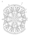
- FIG. 6 is a block diagram of a rotary electric machine having an embedded magnet type rotor in one embodiment.
- (A) to (c) are explanatory views for explaining the characteristic of the rotor in the same form.
- (A) to (c) are explanatory views for explaining the characteristic of the rotor which changed the shape partially in the same form.
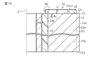
- Cross-sectional view of the rotor in the modified example Cross-sectional view of the rotor in the modified example.
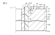
- Cross-sectional view of the rotor in the modified example. Cross-sectional view of the rotor in the modified example.
- Cross-sectional view of the rotor in the modified example Cross-sectional view of the rotor in the modified example.
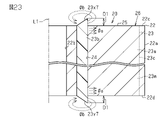
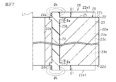
- Cross-sectional view of the rotor in the modified example. An explanatory diagram for explaining the characteristics of the rotor in the embodiment.
- the rotary electric machine M of the present embodiment shown in FIG. 1 is composed of an embedded magnet type brushless motor.
- the rotary electric machine M includes a substantially annular stator 10 and a substantially cylindrical rotor 20 rotatably arranged in the radial inner space of the stator 10.
- the stator 10 includes a substantially annular stator core 11.
- the stator core 11 is made of a magnetic metal material.
- the stator core 11 is configured, for example, by laminating a plurality of electromagnetic steel sheets in the L1 direction of the axis (see FIG. 3).
- the stator core 11 has 12 teeth 12 in the present embodiment extending inward in the radial direction and arranged at equal intervals in the circumferential direction.
- Each tooth 12 has the same shape as each other.
- the radial inner end portion, which is the tip portion has a substantially T shape
- the tip surface 12a has an arc shape following the outer peripheral surface of the rotor 20.
- the winding 13 is wound around the teeth 12 by centralized winding.
- the winding 13 is connected in three phases and functions as a U phase, a V phase, and a W phase, respectively, as shown in FIG. Then, when power is supplied to the winding 13, a rotating magnetic field for rotationally driving the rotor 20 is generated in the stator 10.
- a rotating magnetic field for rotationally driving the rotor 20 is generated in the stator 10.
- the outer peripheral surface of the stator core 11 is fixed to the inner peripheral surface of the housing 14.
- the rotor 20 includes a rotary shaft 21, a substantially columnar rotor core 22 into which the rotary shaft 21 is fitted in a central portion, and eight permanent magnets 23 in the present embodiment in which the rotary shaft 21 is embedded inside the rotor core 22. ing.
- the rotor core 22 is made of a magnetic metal material.
- the rotor core 22 is configured, for example, by laminating a plurality of electromagnetic steel sheets in the direction of the axis L1 shown in FIG.
- the rotor 20 is rotatably arranged with respect to the stator 10 by supporting the rotating shaft 21 with a bearing (not shown) provided in the housing 14.
- the rotor core 22 has a magnet accommodating hole 24 for accommodating the permanent magnet 23.
- Eight magnet accommodating holes 24 are provided in the present embodiment at equal intervals in the circumferential direction of the rotor core 22.
- Each magnet accommodating hole 24 has a substantially V-shaped folded shape that is convex inward in the radial direction, and has the same shape as each other. Further, the magnet accommodating hole 24 is provided over the entire axial direction of the rotor core 22.
- the permanent magnet 23 of the present embodiment is made of a bonded magnet formed by molding and solidifying a magnet material in which magnet powder is mixed with a resin. That is, in the permanent magnet 23, the magnet accommodating hole 24 of the rotor core 22 is molded, and the magnet material before solidification is filled in the magnet accommodating hole 24 without a gap by injection molding, and is solidified in the magnet accommodating hole 24 after filling. It is configured. Therefore, the hole shape of the magnet accommodating hole 24 is the outer shape of the permanent magnet 23. Further, the permanent magnet 23 of the present embodiment is configured to partially protrude from the axial end faces 22c and 22d of the rotor core 22 (see FIG. 3 and the like).
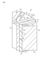
- the permanent magnet 23 has an embedded magnet portion 23m in the magnet accommodating hole 24 and protruding portions 23x1, 23y1 protruding from the axial end faces 22c and 22d of the rotor core 22.
- a recess for forming the protruding portion 23x1,23y1 is provided in a molded mold (not shown) for closing the magnet accommodating holes 24 opened in the axial end faces 22c and 22d of the rotor core 22. It can be easily realized just by providing.
- a sumalium iron nitrogen (SmFeN) magnet is used, but other rare earth magnets or the like may be used.
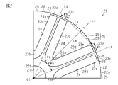
- the permanent magnet 23 has a substantially V-shaped folded shape that is convex inward in the radial direction. More specifically, as shown in FIG. 2, the permanent magnet 23 has a shape in which the radial inner ends of the pair of straight portions 23a are connected to each other by the bent portions 23b. The radial outer end portion 23c of the straight portion 23a is located near the outer peripheral surface 22a of the rotor core 22.
- the permanent magnet 23 has a constant thickness Wm in any of the V-shaped paths including the pair of straight portions 23a and the bent portions 23b.
- the permanent magnet 23 has a line-symmetrical shape with respect to its own circumferential center line Ls passing through the axis center O1 of the rotor 20, and is close to the magnetic pole boundary line Ld passing through the axis center O1 of the rotor 20 between adjacent permanent magnets 23. are doing.
- the angle between the adjacent magnetic pole boundary lines Ld, that is, the magnetic pole opening angle ⁇ m of the rotor magnetic pole portion 26 including the permanent magnet 23 is 180 ° in electrical angle.
- the distance between the intersection of the extension line of the inner surface of each straight line portion 23a of the V-shaped permanent magnet 23 and the outer peripheral surface 22a of the rotor core 22 is the magnetic pole pitch Lp
- the rotor core is on the circumferential center line Ls of the permanent magnet 23.
- the embedding depth is Lm from the outer peripheral surface 22a of 22 to the inner surface of the bent portion 23b.
- the permanent magnet 23 of the present embodiment is set to a deep folded shape so that the embedding depth Lm is larger than the magnetic pole pitch Lp. That is, the magnet surface 23d of the permanent magnet 23 of the present embodiment formed on each inner surface of each straight portion 23a and each bending portion 23b is set to be larger than the well-known surface magnet type magnet surface (not shown).
- the bent portion 23b of the permanent magnet 23 is located in the radial inward position close to the shaft fitting insertion hole 22b in which the rotating shaft 21 is fitted in the central portion of the rotor core 22. are doing.
- This folded shape of the permanent magnet 23 is an example, and can be appropriately changed, such as one having a shallow embedding depth Lm or a substantially U-shaped folded shape having a large bent portion 23b.
- the permanent magnet 23 is provided over the entire axial direction of the rotor core 22.
- the axial end faces 22c and 22d of the rotor core 22 are flat surfaces, and the permanent magnet 23 has protrusions 23x1, 23y1 that project axially from the axial end faces 22c and 22d of the rotor core 22.
- the protruding portions 23x1, 23y1 are continuous in a V-shaped path including the straight portion 23a and the bent portion 23b of the permanent magnet 23, and have a constant thickness Wm.
- the protrusions 23x1, 23y1 are provided on one axial end surface 22c of the rotor core 22 and the other axial end surface 22d, respectively.
- the protruding portions 23x1, 23y1 are continuously and integrally provided with the same material as the embedded magnet portion 23m of the permanent magnet 23 located in the magnet accommodating hole 24 of the rotor core 22.
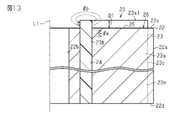
- Such a protruding portion 23x1, 23y1 of the permanent magnet 23 is an end portion of the permanent magnet 23 located at the axial end faces 22c and 22d of the rotor core 22, and the leakage flux easily generated at the end portion of the permanent magnet 23 is shown in FIG. It functions to generate ⁇ b at this site.
- more magnetic flux of the embedded magnet portion 23m located in the rotor core 22 of the permanent magnet 23 is allowed to flow along the radial direction from the axial end faces 22c and 22d without leaking to the outside, and more magnetic flux is generated.
- the effective magnetic flux ⁇ a that contributes to the torque of the rotary electric machine M is set.
- the protrusions 23x1, 23y1 are set so that the amount of protrusion D1 is appropriate from the axial end faces 22c and 22d of the rotor core 22 while increasing the effective magnetic flux ⁇ a.
- the protrusion amount D1 of the protrusions 23x1, 23y1 may differ from the shown dimensions and the actual dimensions.
- the permanent magnet 23 mainly provided in the magnet accommodating hole 24 of the rotor core 22 is magnetized from the outside of the rotor core 22 so as to function as an original magnet by using a magnetizing device (not shown) after the magnet material is solidified.
- Eight permanent magnets 23 are provided in the circumferential direction of the rotor core 22 in the present embodiment, and are magnetized so as to be alternately different in the circumferential direction. Further, each permanent magnet 23 is magnetized in its own thickness direction.
- the portion of the rotor core 22 located inside the V-shaped folded shape of the permanent magnet 23 and radially outside the permanent magnet 23 functions as the outer core portion 25 for obtaining the reluctance torque facing the stator 10.
- the outer core portion 25 has a substantially triangular shape with one apex directed toward the center of the rotor 20 in the axial direction.
- the rotor 20 is configured as an 8-pole rotor magnetic pole portion 26 in the present embodiment including the permanent magnet 23 and the outer core portion 25 surrounded by the inside of the V-shape of the permanent magnet 23. As shown in FIG. 1, each rotor magnetic pole portion 26 functions as an N pole and an S pole alternately in the circumferential direction. In the rotor 20 having such a rotor magnetic pole portion 26, the magnet torque and the reluctance torque can be preferably obtained.
- the permanent magnet 23 embedded in the rotor core 22 protrudes from the axial end faces 22c and 22d on both sides of the rotor core 22 with the ends of the permanent magnets 23 as protrusions 23x1, 23y1 respectively. I'm letting you.
- the leakage flux ⁇ b generated at the end portion of the permanent magnet 23 is concentrated on the protruding portion 23x1,23y1.
- FIG. 5A is a comparison result between this embodiment and a comparative example.
- the ends of the permanent magnets 23 are projected from the axial end faces 22c and 22d on both sides of the rotor core 22 as protrusions 23x1, 23y1 respectively.
- a comparative example is a conventionally known configuration in which the end portion of the permanent magnet 23 is not projected from the axial end faces 22c and 22d of the rotor core 22.
- this embodiment is sufficiently larger than the comparative example. This is because the leakage flux ⁇ b is generated at the protruding portions 23x1, 23y1, so that most of the magnetic flux of the embedded magnet portion 23m of the permanent magnet 23 becomes the effective magnetic flux ⁇ a, and the effective magnetic flux ⁇ a increases.
- FIG. 5B the relationship between the protrusion amount D1 of the protrusion 23x1,23y1 and the induced voltage Vm is shown. However, it can be seen that the induced voltage Vm also rises.
- the induced voltage / magnet volume (Vm / Va) is smaller than that of the comparative example because the magnet volume Va increases by the amount of the protrusions 23x1, 23y1.
- the relationship between the protrusion amount D1 and the induced voltage / magnet volume (Vm / Va) is shown. Can be seen to gradually decrease.
- the protrusion amount D1 is appropriately set in consideration of the relationship between the protrusion amount D1 of the protrusions 23x1, 23y1 and the induced voltage Vm and the induced voltage / magnet volume (Vm / Va). Further, since a large protrusion amount D1 leads to an increase in the weight of the rotor 20 and an increase in the magnet material of the permanent magnet 23, it is also preferable to consider when setting the protrusion amount D1.
- the protruding portions 23x1, 23y1 of the permanent magnet 23 are continuous in a V-shaped path including the straight portion 23a and the bent portion 23b of the permanent magnet 23, and are constant in thickness Wm.
- FIGS. 7 and 8 a case in which the thickness Wm1 of the bent portion 23b of the permanent magnet 23 is narrower than the thickness Wm of the straight portion 23a is also examined.
- FIG. 9A is a comparison result between a form in which the bent portion 23b has a thickness of Wm1 and a slightly narrow width and a comparative example.
- this embodiment is larger than the comparative example.
- the bent portion 23b of the magnet 23 is a portion where the magnetic flux leaks less than that of the straight portion 23a, it is possible to adjust the thickness Wm1 of the bent portion 23b to be slightly narrower.
- the thickness Wm1 of the bent portion 23b of the permanent magnet 23 is appropriately changed so that both the Vm value and the Vm / Va value are larger than those in the comparative example.
- the relationship between the protrusion amount D1 of the protrusion 23x1,23y1 and the induced voltage Vm shown in FIG. 9B when the protrusion amount D1 of the protrusion 23x1,23y1 becomes zero or more, the effective magnetic flux ⁇ a increases. The Vm value increases, but in this embodiment, the change reaches a plateau early.
- the embedded magnet portion 23m of the permanent magnet 23 located in the rotor core 22 In order for the magnetic flux of the rotor core 22 to leak from the axial end faces 22c and 22d of the rotor core 22, the protrusion exceeds the protrusions 23x1,23y1. That is, since the path length at which the magnetic flux of the embedded magnet portion 23m tends to leak becomes long, it is possible to suppress the leakage of the magnetic flux of the embedded magnet portion 23m.
- the magnetic flux of the embedded magnet portion 23m of the permanent magnet 23 becomes an effective magnetic flux ⁇ a that contributes to the torque of the rotary electric machine M
- the magnetic flux amount of the effective magnetic flux ⁇ a is increased by preventing this from leaking as much as possible. It can be fully expected that the torque performance of M will be improved.
- the axial end faces 22c and 22d of the rotor core 22 have a general flat surface shape, and the end portion of the permanent magnet 23 can be realized by simply projecting from the axial end faces 22c and 22d of the rotor core 22. be able to.
- the protruding portions 23x1, 23y1 of the permanent magnet 23 are continuously provided in the extending direction of the V-shape of the permanent magnet 23 along the axial end faces 22c and 22d of the rotor core 22, they are embedded to contribute to the torque. Leakage of the magnetic flux of the magnet portion 23m can be more reliably suppressed over the entire permanent magnet 23.
- the protruding portions 23x1, 23y1 of the permanent magnet 23 are provided so that the amount of protrusion D1 from the axial end faces 22c and 22d of the rotor core 22 is constant, so that the magnetic flux of the embedded magnet portion 23m that contributes to torque is increased. Leakage can be similarly suppressed at each location.
- the protruding portions 23x1, 23y1 of the permanent magnet 23 are continuously and integrally provided from the embedded magnet portion 23m of the rotor core 22, they can be easily formed by using the same material at the same time.
- the configuration of the protruding portions 23x1, 23y1 at the ends of the permanent magnets 23 protruding from the axial end faces 22c and 22d of the rotor core 22 may be appropriately changed.
- a protruding portion may be partially provided in a V-shaped path including a straight portion 23a and a bent portion 23b of the permanent magnet 23.
- a protruding portion 23x2, 23y2 that protrudes only from the bent portion 23b of the permanent magnet 23 may be provided.
- the protrusions 23x2 and 23y2 are similarly provided on both the axial end faces 22c and 22d of the rotor core 22.
- a protruding portion 23x3, 23y3 that protrudes only from the straight portion 23a of the permanent magnet 23 may be provided.
- the protrusions 23x3 and 23y3 are similarly provided on both the axial end faces 22c and 22d of the rotor core 22.
- a protruding portion 23x2, 23y2 protruding from the bent portion 23b of the permanent magnet 23 and a protruding portion 23x4, 23y4 partially protruding in the extending direction of the straight line portion 23a may be provided.
- the protrusions 23x2, 23y2 and the protrusions 23x4, 23y4 are similarly provided on both the axial end faces 22c and 22d of the rotor core 22.
- the protruding portion of the permanent magnet 23 may be provided on only one side of the V-shape, such as a straight portion 23a on one side of the V-shape of the permanent magnet 23 and half of the bent portion 23b.
- the magnet material of the permanent magnet 23 can be reduced, and the effect of reducing the weight of the rotor 20 can be expected.
- each of the axial end faces 22c and 22d of the rotor core 22 may be provided with protrusions having different configurations. Among them, the mode in which the protruding portion is provided only on one side of the axial end faces 22c and 22d of the rotor core 22 is listed first.
- the protrusion 23x1 may be provided only on the axial end surface 22c side of the rotor core 22. As described above, the protruding portion 23x1 is continuous along the V-shaped path of the permanent magnet 23.
- a protruding portion 23x2 that protrudes only from the bent portion 23b of the permanent magnet 23 may be provided only on the axial end surface 22c side of the rotor core 22.
- a protruding portion 23x3 that protrudes only from the linear portion 23a of the permanent magnet 23 may be provided only on the axial end surface 22c side of the rotor core 22.
- the protruding portion 23x2 protruding from the bent portion 23b of the permanent magnet 23 and the protruding portion 23x4 partially protruding in the extending direction of the straight portion 23a are provided. It may be provided.
- the magnet material of the permanent magnet 23 can be reduced, and the effect of reducing the weight of the rotor 20 can be expected.
- a protruding portion 23x2 is provided that protrudes only by the bent portion 23b of the permanent magnet 23, and on the axial end surface 22d side of the rotor core 22, the bent portion of the permanent magnet 23 is provided.
- a protruding portion 23y2 protruding from the 23b and a protruding portion 23y4 partially protruding in the extending direction of the straight portion 23a may be provided.
- a continuous protrusion 23x1 is provided along the V-shaped path of the permanent magnet 23, and on the axial end surface 22d side of the rotor core 22, a straight line of the permanent magnet 23 is provided.
- a protruding portion 23y3 that protrudes only from the portion 23a may be provided.
- a protruding portion 23x2 protruding from the bent portion 23b of the permanent magnet 23 and a protruding portion 23x4 partially protruding in the extending direction of the straight portion 23a are provided on the axial end surface 22d side of the rotor core 22 .
- a continuous protrusion 23y1 may be provided along the V-shaped path of the permanent magnet 23.
- the protruding portion may be partially provided in the thickness direction orthogonal to the extending direction of the V-shaped path of the permanent magnet 23.
- a protruding portion 23x5, 23y5 having a narrow shape may be provided at the central portion in the thickness direction of the permanent magnet 23.
- the protrusions 23x5 and 23y5 are continuous along the V-shaped path of the permanent magnet 23. Further, the protrusions 23x5 and 23y5 are similarly provided on both the axial end faces 22c and 22d of the rotor core 22.
- a protruding portion 23x6, 23y6 having a groove portion 23z1 may be provided at the central portion in the thickness direction of the permanent magnet 23.
- the groove portion 23z1 has the same depth as the protrusion amount D1 of the protrusions 23x6, 23y6.
- the protrusions 23x6, 23y6 are continuous along the V-shaped path of the permanent magnet 23. Further, the protrusions 23x6, 23y6 are similarly provided on both the axial end faces 22c and 22d of the rotor core 22.
- the depth of the groove portion 23z2 provided in the central portion of the protruding portion 23x6, 23y6 of the permanent magnet 23 in the thickness direction may be different from the protruding amount D1 of the protruding portion 23x6, 23y6.
- the groove portion 23z2 may be shallower or deeper than the protrusion amount D1 of the protrusions 23x6, 23y6 as shown in FIG. 22.
- the magnet material of the permanent magnet 23 can be reduced, and the effect of reducing the weight of the rotor 20 can be expected.
- the shape of the protruding portion provided on the permanent magnet 23 may be changed.
- the protrusion amount D1 may be changed depending on the portion of the protrusion.
- the protruding portions 23x7, 23y7 provided in the bent portion 23b of the permanent magnet 23 may have a slope shape.
- the protrusions 23x7 and 23y7 are formed in a slope shape in which the inside of the V-shape of the permanent magnet 23 is high and the outside is low.
- the protrusions 23x7 and 23y7 are similarly provided on both the axial end faces 22c and 22d of the rotor core 22.
- protrusions 23x8, 23y8 that are continuous in the extending direction of the V-shaped path of the permanent magnet 23, the bent portion 23b is the highest, and the radial outer end portion 23c of the straight portion 23a is reached. It may be a slope shape that gradually becomes lower toward the bottom.
- the protrusions 23x8 and 23y8 are similarly provided on both the axial end faces 22c and 22d of the rotor core 22.
- the magnet material of the permanent magnet 23 can be reduced, and the effect of reducing the weight of the rotor 20 can be expected. Further, it is expected that the degree of freedom of the outer shape of the rotor 20 including the protruding shape of the permanent magnet 23 can be increased.
- the protruding portion of the permanent magnet 23 may be separated from the embedded magnet portion 23 m.
- the magnet materials may be different from each other.
- the protruding portions 23x9, 23y9 of the permanent magnet 23 are continuous in the extending direction of the V-shaped path, and are similarly provided on both the axial end faces 22c and 22d of the rotor core 22.
- the protruding portions 23x9 and 23y9 may use a magnet material that is cheaper than the embedded magnet portion 23m. Further, the protruding portions 23x9 and 23y9 may use a magnet material having a magnetic force different from that of the embedded magnet portion 23m.
- the protruding portions 23x9 and 23y9 may be made of a magnet material having a strength different from that of the embedded magnet portion 23m, and may be configured to have high strength in consideration of being exposed from the axial end faces 22c and 22d of the rotor core 22. .. Further, the protruding portions 23x9 and 23y9 may be formed at the same time as the embedded magnet portion 23m, or may be retrofitted.
- a protrusion 23x1 may be selectively provided in every other permanent magnet 23 arranged in the circumferential direction. In addition, it may be placed at equal intervals other than every other one, or it may be placed at unequal intervals.
- the magnet material of the permanent magnet 23 can be reduced, and the effect of reducing the weight of the rotor 20 can be expected.
- the recess 24a in which the margin of the magnet material is accumulated when the permanent magnet 23 including the protrusions 23x1, 23y1 is formed is formed in the magnet accommodating hole 24. It may be provided around the opening. By doing so, since the margin of the magnet material can be accommodated in the recess 24a, it is possible to suppress the protrusion of the permanent magnet 23 as a burr on the axial end faces 22c and 22d of the rotor core 22.
- the permanent magnet 23 is not limited to a V-shape, but may have another folded shape that is convex inward in the radial direction of the rotor 20, such as a U-shape. Further, it may have a shape other than the folded shape such as an I shape.
- a permanent magnet 23 is formed by injection molding a magnet material into the magnet accommodating hole 24 of the rotor core 22. However, the permanent magnet 23 is prepared in advance and inserted into the magnet accommodating hole 24 of the rotor core 22 to be fixed. You may.
- the configuration of the rotor 20 and the configuration of the rotary electric machine M may be changed as appropriate.
- FIG. 28 is a graph comparing the magnitudes of the induced voltage Vm generated in the rotary electric machine M in the comparative configuration 1, the comparative configuration 2, and the above embodiment.
- the axial length of the stator core 11 is set to be equal to the axial length of the rotor core 22.
- the axial length of the stator core 11 is, for example, the axial length of the tip surface 12a of the teeth 12.
- the protruding portion 23x1,23y1 is formed by forming the permanent magnet 23 in the axial direction longer than the axial length of the rotor core 22. That is, in the above embodiment, the axial length of the permanent magnet 23 is longer than the axial length of the rotor core 22 and the stator core 11.
- the protruding portions 23x1, 23y1 of the permanent magnet 23 are located laterally in the axial direction with respect to both end faces in the axial direction of the stator core 11.
- the comparative configuration 1 has a configuration in which the axial lengths of the permanent magnet 23, the rotor core 22, and the stator core 11 are equal to each other.
- the axial length of the permanent magnet 23 is set equal to the axial length of the rotor core 22. That is, in the comparative configuration 2, a portion where the permanent magnet 23 protrudes in the axial direction from the magnet accommodating hole 24 is not formed. Further, in the comparative configuration 2, the axial lengths of the rotor core 22 and the permanent magnet 23 are set longer than the axial length of the stator core 11.
- the induced voltage Vm is larger in the comparative configuration 2 and the above embodiment than in the comparative configuration 1. It is considered that this is because the entire axial direction of the stator core 11 is included in the axial range of the permanent magnet 23.
- the magnitudes of the induced voltage Vm are almost the same.
- the axial length of the rotor core 22 is equal to the axial length of the stator core 11, and the axial length of only the permanent magnet 23 is increased. Therefore, in the above embodiment, the axial length of the rotor core 22 can be shortened with respect to the comparative configuration 2. Therefore, as in the above embodiment, by forming the axial length of the permanent magnet 23 longer than the axial length of the rotor core 22 and the stator core 11, the induced voltage Vm is improved, and the weight of the rotor core 22 and thus the rotary electric machine M is reduced. Can contribute to the conversion.
- the rotor core 22 is composed of a single component, but in addition to this, for example, the rotor core 22 may be configured by a plurality of rotor core portions arranged side by side in the axial direction.
- the rotor core 22 is configured by two rotor core portions arranged side by side in the axial direction.
- one of the two rotor core portions will be referred to as a first rotor core portion 31, and the other will be referred to as a second rotor core portion 32.
- the same configurations as those in the above embodiment may be designated by the same reference numerals as those in the above embodiment, and detailed description thereof may be omitted.
- the rotor 20 includes a rotating shaft 21, a first rotor portion R1 having a first rotor core portion 31, and a second rotor portion R2 having a second rotor core portion 32.
- the first rotor portion R1 and the second rotor portion R2 are arranged side by side in the direction along the axis L1 of the rotor 20.
- the first rotor portion R1 and the second rotor portion R2 are configured to be integrally rotatable with the rotating shaft 21.
- the first rotor portion R1 and the second rotor portion R2 are rotatably arranged with respect to the stator 10 by supporting the rotating shaft 21 with a bearing (not shown) provided in the housing 14.
- the first rotor core portion 31 has a substantially cylindrical shape in which the rotating shaft 21 is inserted into the central portion.
- the second rotor core portion 32 also has a substantially cylindrical shape in which the rotating shaft 21 is fitted into the central portion.
- the first rotor portion R1 includes a permanent magnet 23 embedded in the first rotor core portion 31.
- the second rotor portion R2 includes a permanent magnet 23 embedded in the second rotor core portion 32.
- the first rotor core portion 31 and the second rotor core portion 32 are, for example, parts having the same structure.
- Each of the first rotor core portion 31 and the second rotor core portion 32 is made of a magnetic metal material.
- Each of the first rotor core portion 31 and the second rotor core portion 32 is configured by, for example, laminating a plurality of electromagnetic steel sheets in the axis L1 direction.
- the first rotor core portion 31 and the second rotor core portion 32 are arranged side by side in the axial direction to form the rotor core 22.
- the cross-sectional shape orthogonal to the axis L1 is, for example, the same as the cross-sectional shape orthogonal to the axis L1 in the rotor core 22 of the above embodiment. That is, the first rotor core portion 31 and the second rotor core portion 32 each have a magnet accommodating hole 24 for accommodating the permanent magnet 23.
- the configuration such as the number and shape of the magnet accommodating holes 24 in the circumferential direction is the same as, for example, the magnet accommodating holes 24 of the above embodiment.
- each of the first rotor core portion 31 and the second rotor core portion 32 the portion located inside the V-shaped folded shape of the permanent magnet 23 and radially outside the permanent magnet 23 is opposed to the stator 10 and has a reluctance torque. Functions as the outer core portion 25 for obtaining.
- Each of the first rotor portion R1 and the second rotor portion R2 has eight rotor magnetic pole portions 26 including a permanent magnet 23 and an outer core portion 25. The rotor magnetic poles 26 alternately function as N poles and S poles in the circumferential direction.
- each rotor magnetic pole portion 26 has a magnetic pole center C in the circumferential direction.
- the magnetic pole centers C are set at equal intervals from each other in the circumferential direction.
- the magnetic pole centers C of each of the eight rotor magnetic pole portions 26 are set at intervals of 45 ° in the circumferential direction.
- the magnetic pole center C coincides with the circumferential center line Ls of the permanent magnet 23.
- the rotor magnetic pole portion 26 of the second rotor portion R2 is displaced in the circumferential direction with respect to the rotor magnetic pole portion 26 of the first rotor portion R1.
- the first rotor portion R1 and the second rotor portion R2 have the same configuration as each other, and the second rotor portion R2 is rotated by a predetermined angle with respect to the first rotor portion R1 to form a rotor 20.
- the magnetic pole center C of the second rotor portion R2 is displaced by a predetermined angle in the circumferential direction with respect to the magnetic pole center C of the first rotor portion R1.
- the deviation angle of the second rotor portion R2 with respect to the magnetic pole center C of the first rotor portion R1 in the circumferential direction is referred to as a skew angle ⁇ .
- the skew angle ⁇ in this example is set based on the following equation (a), where p is the number of poles of the rotor 20, and L is the least common multiple of the number of poles p and the number of slots of the stator 10.
- FIG. 30 shows the relationship between the rotation angle of the rotor 20 and the magnitude of the cogging torque in the configuration in which the skew angle ⁇ is set to 7.5 [°].
- the cogging torque generated in the first rotor portion R1 is T1
- the cogging torque generated in the second rotor portion R2 is T2
- the combined cogging torque generated in the entire rotor 20 in which the cogging torques T1 and T2 are combined is T3.
- the skew angle ⁇ is 7.5 [°]
- the cogging torque T1 and the cogging torque T2 are in opposite phases to each other.
- the cogging torques T1 and T2 are canceled out, whereby the combined cogging torque T3 is reduced.
- the combined cogging torque T3 of the entire rotor 20 can be reduced.
- the value of the skew angle ⁇ in this example is an example, and the value of the skew angle ⁇ can be appropriately changed according to the configuration of the rotary electric machine M.
- the rotor 20 of this example also has a protruding portion 23x1,23y1 which is a portion of a permanent magnet 23 protruding in the axial direction from the rotor core 22.
- the protruding portion 23x1 protrudes from one axial end surface 22c of the rotor core 22.
- the axial end surface 22c of the rotor core 22 is the end surface of the first rotor core portion 31 opposite to the second rotor portion R2.
- the protruding portion 23x1 is a part of the permanent magnet 23 of the first rotor portion R1.
- the protruding portion 23y1 protrudes from the other axial end surface 22d of the rotor core 22.
- the axial end surface 22d of the rotor core 22 is the end surface of the second rotor core portion 32 opposite to the first rotor portion R1.
- the protruding portion 23y1 is a part of the permanent magnet 23 of the second rotor portion R2.
- the permanent magnet 23 does not project from the axial end face on the opposite side of the axial end face 22c where the protruding portion 23x1 is provided.
- the permanent magnet 23 does not protrude from the axial end face on the side opposite to the axial end face 22d where the protruding portion 23y1 is provided.
- the first rotor core portion 31 and the second rotor core portion 32 are arranged side by side in such a manner that the end faces in the axial direction in which the permanent magnets 23 do not project are opposed to each other in the axial direction.
- the first rotor core portion 31 and the second rotor core portion 32 are arranged side by side so that the axial end faces are in contact with each other.
- the axial end faces of the permanent magnets 23 are not projected, and the axial end faces are in contact with each other.
- a gap may be provided in the.
- the permanent magnet 23 may be configured so as to project from the axial end faces of the first rotor core portion 31 and the second rotor core portion 32 facing each other.
- M rotary electric machine 10 stator, 20 rotor, 22 rotor core, 22c, 22d axial end face, 23 permanent magnet, 23m embedded magnet part, 23x1-23x9, 23y1-23y9 protrusion, 24 magnet accommodation hole, D1 protrusion amount, R1 1st rotor part (rotor part), R2 2nd rotor part (rotor part), 31 1st rotor core part (rotor core part), 32 2nd rotor core part (rotor core part), C magnetic pole center.
Landscapes
- Engineering & Computer Science (AREA)
- Power Engineering (AREA)
- Permanent Field Magnets Of Synchronous Machinery (AREA)
Priority Applications (4)
| Application Number | Priority Date | Filing Date | Title |
|---|---|---|---|
| JP2022557323A JPWO2022080110A1 (https=) | 2020-10-15 | 2021-09-22 | |
| CN202180070021.9A CN116325432A (zh) | 2020-10-15 | 2021-09-22 | 转子和旋转电机 |
| DE112021005414.7T DE112021005414T5 (de) | 2020-10-15 | 2021-09-22 | Rotor und rotierende elektrische maschine |
| US18/133,151 US12519356B2 (en) | 2020-10-15 | 2023-04-11 | Rotor and rotating electric machine |
Applications Claiming Priority (4)
| Application Number | Priority Date | Filing Date | Title |
|---|---|---|---|
| JP2020-173869 | 2020-10-15 | ||
| JP2020173869 | 2020-10-15 | ||
| JPPCT/JP2021/030888 | 2021-08-24 | ||
| PCT/JP2021/030888 WO2022080010A1 (ja) | 2020-10-15 | 2021-08-24 | ロータ及び回転電機 |
Related Child Applications (1)
| Application Number | Title | Priority Date | Filing Date |
|---|---|---|---|
| US18/133,151 Continuation US12519356B2 (en) | 2020-10-15 | 2023-04-11 | Rotor and rotating electric machine |
Publications (1)
| Publication Number | Publication Date |
|---|---|
| WO2022080110A1 true WO2022080110A1 (ja) | 2022-04-21 |
Family
ID=81207912
Family Applications (1)
| Application Number | Title | Priority Date | Filing Date |
|---|---|---|---|
| PCT/JP2021/034893 Ceased WO2022080110A1 (ja) | 2020-10-15 | 2021-09-22 | ロータ及び回転電機 |
Country Status (5)
| Country | Link |
|---|---|
| US (1) | US12519356B2 (https=) |
| JP (1) | JPWO2022080110A1 (https=) |
| CN (1) | CN116325432A (https=) |
| DE (1) | DE112021005414T5 (https=) |
| WO (1) | WO2022080110A1 (https=) |
Families Citing this family (2)
| Publication number | Priority date | Publication date | Assignee | Title |
|---|---|---|---|---|
| US20240364148A1 (en) * | 2023-04-26 | 2024-10-31 | Abb Schweiz Ag | Non-Exchanged-Couple Injection Moldable Hybrid Magnet |
| CN118983969A (zh) * | 2024-10-21 | 2024-11-19 | 浙江永昌电气股份有限公司 | 无稀土永磁高效低燥电机结构及制造方法 |
Citations (5)
| Publication number | Priority date | Publication date | Assignee | Title |
|---|---|---|---|---|
| JPH11136888A (ja) * | 1997-10-28 | 1999-05-21 | Toshiba Corp | 永久磁石形モータ及びその製造方法 |
| JP2013051837A (ja) * | 2011-08-31 | 2013-03-14 | Daikin Ind Ltd | 回転電気機械 |
| JP2016167907A (ja) * | 2015-03-09 | 2016-09-15 | 三菱電機株式会社 | 回転電機および電動パワーステアリング装置 |
| JP2017070031A (ja) * | 2015-09-29 | 2017-04-06 | ダイキン工業株式会社 | ロータ |
| WO2018198866A1 (ja) * | 2017-04-24 | 2018-11-01 | パナソニックIpマネジメント株式会社 | 電動機要素、電動機、装置 |
Family Cites Families (7)
| Publication number | Priority date | Publication date | Assignee | Title |
|---|---|---|---|---|
| JP2006158008A (ja) * | 2004-11-25 | 2006-06-15 | Asmo Co Ltd | 永久磁石埋め込み型ロータ及び回転電機 |
| MX347464B (es) * | 2012-09-29 | 2017-04-26 | Emerson Electric Co | Rotores con configuraciones de iman segmentado y maquinas dinamoeléctricas y compresores relacionados. |
| WO2014082839A2 (en) * | 2012-11-30 | 2014-06-05 | Arcelik Anonim Sirketi | A spoke permanent magnet rotor |
| JP6408766B2 (ja) * | 2014-01-28 | 2018-10-17 | 日本ピストンリング株式会社 | アキシャル立体ギャップ式回転電機 |
| JP2016072995A (ja) | 2014-09-26 | 2016-05-09 | パナソニックIpマネジメント株式会社 | 埋め込み磁石型ロータおよびそれを備えた電動機 |
| CN106469953A (zh) * | 2015-08-18 | 2017-03-01 | 珠海格力节能环保制冷技术研究中心有限公司 | 一种电机及其转子 |
| WO2018131402A1 (ja) * | 2017-01-11 | 2018-07-19 | パナソニックIpマネジメント株式会社 | 永久磁石埋込型の回転子およびこれを備えた電動機 |
-
2021
- 2021-09-22 DE DE112021005414.7T patent/DE112021005414T5/de active Pending
- 2021-09-22 CN CN202180070021.9A patent/CN116325432A/zh active Pending
- 2021-09-22 JP JP2022557323A patent/JPWO2022080110A1/ja active Pending
- 2021-09-22 WO PCT/JP2021/034893 patent/WO2022080110A1/ja not_active Ceased
-
2023
- 2023-04-11 US US18/133,151 patent/US12519356B2/en active Active
Patent Citations (5)
| Publication number | Priority date | Publication date | Assignee | Title |
|---|---|---|---|---|
| JPH11136888A (ja) * | 1997-10-28 | 1999-05-21 | Toshiba Corp | 永久磁石形モータ及びその製造方法 |
| JP2013051837A (ja) * | 2011-08-31 | 2013-03-14 | Daikin Ind Ltd | 回転電気機械 |
| JP2016167907A (ja) * | 2015-03-09 | 2016-09-15 | 三菱電機株式会社 | 回転電機および電動パワーステアリング装置 |
| JP2017070031A (ja) * | 2015-09-29 | 2017-04-06 | ダイキン工業株式会社 | ロータ |
| WO2018198866A1 (ja) * | 2017-04-24 | 2018-11-01 | パナソニックIpマネジメント株式会社 | 電動機要素、電動機、装置 |
Also Published As
| Publication number | Publication date |
|---|---|
| JPWO2022080110A1 (https=) | 2022-04-21 |
| US12519356B2 (en) | 2026-01-06 |
| US20230246496A1 (en) | 2023-08-03 |
| DE112021005414T5 (de) | 2023-08-03 |
| CN116325432A (zh) | 2023-06-23 |
Similar Documents
| Publication | Publication Date | Title |
|---|---|---|
| US10734852B2 (en) | Motor | |
| WO2022080010A1 (ja) | ロータ及び回転電機 | |
| JP6950361B2 (ja) | モータ | |
| JP5602815B2 (ja) | 永久磁石を位置決めするための突起を有する回転子及びそのような回転子を備える電動機 | |
| JP6950275B2 (ja) | ロータ及びモータ | |
| US20240030761A1 (en) | Rotor and rotating electric machine | |
| WO2022080110A1 (ja) | ロータ及び回転電機 | |
| JP7501693B2 (ja) | 回転電機及び回転電機の製造方法 | |
| JP6357859B2 (ja) | 永久磁石埋め込み式回転電機 | |
| JP2021027724A (ja) | ロータ及びモータ | |
| JP7367552B2 (ja) | ロータ | |
| JP7690839B2 (ja) | 回転電機 | |
| JP2005198381A (ja) | バーニアモータ | |
| JP2005210828A (ja) | 回転電機のロータおよび回転電機 | |
| WO2022219896A1 (ja) | 回転電機のロータ、回転電機及び電動駆動システム | |
| JP7582078B2 (ja) | ロータ及び回転電機 | |
| WO2022114075A1 (ja) | ロータ及び回転電機 | |
| JP7567648B2 (ja) | 回転電機 | |
| JP7563225B2 (ja) | ロータの製造装置、ロータの製造方法及びロータ | |
| KR101221251B1 (ko) | 매입형 영구자석 모터의 회전자 | |
| JP2013027106A (ja) | 永久磁石式モータ | |
| JP7318556B2 (ja) | ロータ | |
| JP2024166515A (ja) | 埋込磁石型モータ |
Legal Events
| Date | Code | Title | Description |
|---|---|---|---|
| 121 | Ep: the epo has been informed by wipo that ep was designated in this application |
Ref document number: 21879851 Country of ref document: EP Kind code of ref document: A1 |
|
| ENP | Entry into the national phase |
Ref document number: 2022557323 Country of ref document: JP Kind code of ref document: A |
|
| 122 | Ep: pct application non-entry in european phase |
Ref document number: 21879851 Country of ref document: EP Kind code of ref document: A1 |