WO2022080110A1 - Rotor and rotary electric machine - Google Patents
Rotor and rotary electric machine Download PDFInfo
- Publication number
- WO2022080110A1 WO2022080110A1 PCT/JP2021/034893 JP2021034893W WO2022080110A1 WO 2022080110 A1 WO2022080110 A1 WO 2022080110A1 JP 2021034893 W JP2021034893 W JP 2021034893W WO 2022080110 A1 WO2022080110 A1 WO 2022080110A1
- Authority
- WO
- WIPO (PCT)
- Prior art keywords
- rotor
- permanent magnet
- rotor core
- magnet
- axial end
- Prior art date
Links
Images


Classifications
-
- H—ELECTRICITY
- H02—GENERATION; CONVERSION OR DISTRIBUTION OF ELECTRIC POWER
- H02K—DYNAMO-ELECTRIC MACHINES
- H02K1/00—Details of the magnetic circuit
- H02K1/06—Details of the magnetic circuit characterised by the shape, form or construction
- H02K1/22—Rotating parts of the magnetic circuit
- H02K1/27—Rotor cores with permanent magnets
- H02K1/2706—Inner rotors
- H02K1/272—Inner rotors the magnetisation axis of the magnets being perpendicular to the rotor axis
- H02K1/274—Inner rotors the magnetisation axis of the magnets being perpendicular to the rotor axis the rotor consisting of two or more circumferentially positioned magnets
- H02K1/2753—Inner rotors the magnetisation axis of the magnets being perpendicular to the rotor axis the rotor consisting of two or more circumferentially positioned magnets the rotor consisting of magnets or groups of magnets arranged with alternating polarity
- H02K1/276—Magnets embedded in the magnetic core, e.g. interior permanent magnets [IPM]
- H02K1/2766—Magnets embedded in the magnetic core, e.g. interior permanent magnets [IPM] having a flux concentration effect
- H02K1/2773—Magnets embedded in the magnetic core, e.g. interior permanent magnets [IPM] having a flux concentration effect consisting of tangentially magnetized radial magnets
-
- H—ELECTRICITY
- H02—GENERATION; CONVERSION OR DISTRIBUTION OF ELECTRIC POWER
- H02K—DYNAMO-ELECTRIC MACHINES
- H02K1/00—Details of the magnetic circuit
- H02K1/02—Details of the magnetic circuit characterised by the magnetic material
-
- H—ELECTRICITY
- H02—GENERATION; CONVERSION OR DISTRIBUTION OF ELECTRIC POWER
- H02K—DYNAMO-ELECTRIC MACHINES
- H02K21/00—Synchronous motors having permanent magnets; Synchronous generators having permanent magnets
- H02K21/12—Synchronous motors having permanent magnets; Synchronous generators having permanent magnets with stationary armatures and rotating magnets
- H02K21/14—Synchronous motors having permanent magnets; Synchronous generators having permanent magnets with stationary armatures and rotating magnets with magnets rotating within the armatures
- H02K21/16—Synchronous motors having permanent magnets; Synchronous generators having permanent magnets with stationary armatures and rotating magnets with magnets rotating within the armatures having annular armature cores with salient poles
-
- H—ELECTRICITY
- H02—GENERATION; CONVERSION OR DISTRIBUTION OF ELECTRIC POWER
- H02K—DYNAMO-ELECTRIC MACHINES
- H02K2201/00—Specific aspects not provided for in the other groups of this subclass relating to the magnetic circuits
- H02K2201/06—Magnetic cores, or permanent magnets characterised by their skew
-
- H—ELECTRICITY
- H02—GENERATION; CONVERSION OR DISTRIBUTION OF ELECTRIC POWER
- H02K—DYNAMO-ELECTRIC MACHINES
- H02K2213/00—Specific aspects, not otherwise provided for and not covered by codes H02K2201/00 - H02K2211/00
- H02K2213/03—Machines characterised by numerical values, ranges, mathematical expressions or similar information
Definitions
- the present invention relates to an embedded magnet type rotor and a rotary electric machine.
- a rotary electric machine that uses an embedded magnet type (IPM type) rotor is well known.
- the embedded magnet type rotor has a configuration in which a permanent magnet is embedded inside the rotor core, and in addition to the magnet torque generated by the permanent magnet, a reluctance torque is obtained at the outer core portion located radially outside the permanent magnet. It has become.
- leakage flux is likely to occur at the end of the permanent magnet located on the axial end face of the rotor core due to the arrangement of the permanent magnets, etc., and torque performance is particularly high when the effective magnetic flux leaks. Since it leads to a decrease in the amount of magnetic flux, various proposals have been made in the past regarding countermeasures (see, for example, Patent Document 1).
- An object of the present invention is to provide a rotor and a rotary electric machine which can be expected to improve torque performance by suppressing leakage of an effective magnetic flux of a permanent magnet with a simple response.
- the rotor that solves the above problems is a rotor (20) having a permanent magnet (23) embedded in a magnet accommodating hole (24) of the rotor core (22), and is an axial end surface (22c, 22d) of the rotor core. ) Form a flat surface, and the permanent magnet is configured to have a protruding portion (23x1 to 23x9, 23y1 to 23y9) having at least a part protruding from the axial end surface of the rotor core.
- Rotating electric machines that solve the above problems include a rotor (20) having a permanent magnet (23) embedded in a magnet accommodating hole (24) of the rotor core (22) and a stator that applies a rotating magnetic field to the rotor.
- the axial end faces (22c, 22d) of the rotor core have a flat surface
- the permanent magnet is at least one from the axial end face of the rotor core.
- the rotor was configured with protruding portions (23x1 to 23x9, 23y1 to 23y9) having protruding portions.
- the magnetic flux of the embedded magnet portion of the permanent magnet located in the rotor core is the rotor core.
- the protrusion is crossed. That is, since the path length at which the magnetic flux of the embedded magnet portion tries to leak becomes long, the leakage of the magnetic flux of the embedded magnet portion is suppressed.
- the magnetic flux of the embedded magnet part of the permanent magnet becomes an effective magnetic flux that contributes to the torque of the rotating electric machine
- the torque performance of the rotating electric machine is improved by increasing the amount of magnetic flux of the effective magnetic flux by preventing this from leaking as much as possible.
- the axial end face of the rotor core has a general flat surface shape, and it can be realized by simply projecting the end portion of the permanent magnet from the axial end face of the rotor core.
- FIG. 6 is a block diagram of a rotary electric machine having an embedded magnet type rotor in one embodiment.
- (A) to (c) are explanatory views for explaining the characteristic of the rotor in the same form.
- (A) to (c) are explanatory views for explaining the characteristic of the rotor which changed the shape partially in the same form.
- Cross-sectional view of the rotor in the modified example Cross-sectional view of the rotor in the modified example.
- Cross-sectional view of the rotor in the modified example. Cross-sectional view of the rotor in the modified example.
- Cross-sectional view of the rotor in the modified example Cross-sectional view of the rotor in the modified example.
- Cross-sectional view of the rotor in the modified example. An explanatory diagram for explaining the characteristics of the rotor in the embodiment.
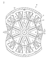
- the rotary electric machine M of the present embodiment shown in FIG. 1 is composed of an embedded magnet type brushless motor.
- the rotary electric machine M includes a substantially annular stator 10 and a substantially cylindrical rotor 20 rotatably arranged in the radial inner space of the stator 10.
- the stator 10 includes a substantially annular stator core 11.
- the stator core 11 is made of a magnetic metal material.
- the stator core 11 is configured, for example, by laminating a plurality of electromagnetic steel sheets in the L1 direction of the axis (see FIG. 3).
- the stator core 11 has 12 teeth 12 in the present embodiment extending inward in the radial direction and arranged at equal intervals in the circumferential direction.
- Each tooth 12 has the same shape as each other.
- the radial inner end portion, which is the tip portion has a substantially T shape
- the tip surface 12a has an arc shape following the outer peripheral surface of the rotor 20.
- the winding 13 is wound around the teeth 12 by centralized winding.
- the winding 13 is connected in three phases and functions as a U phase, a V phase, and a W phase, respectively, as shown in FIG. Then, when power is supplied to the winding 13, a rotating magnetic field for rotationally driving the rotor 20 is generated in the stator 10.
- a rotating magnetic field for rotationally driving the rotor 20 is generated in the stator 10.
- the outer peripheral surface of the stator core 11 is fixed to the inner peripheral surface of the housing 14.
- the rotor 20 includes a rotary shaft 21, a substantially columnar rotor core 22 into which the rotary shaft 21 is fitted in a central portion, and eight permanent magnets 23 in the present embodiment in which the rotary shaft 21 is embedded inside the rotor core 22. ing.
- the rotor core 22 is made of a magnetic metal material.
- the rotor core 22 is configured, for example, by laminating a plurality of electromagnetic steel sheets in the direction of the axis L1 shown in FIG.
- the rotor 20 is rotatably arranged with respect to the stator 10 by supporting the rotating shaft 21 with a bearing (not shown) provided in the housing 14.
- the rotor core 22 has a magnet accommodating hole 24 for accommodating the permanent magnet 23.
- Eight magnet accommodating holes 24 are provided in the present embodiment at equal intervals in the circumferential direction of the rotor core 22.
- Each magnet accommodating hole 24 has a substantially V-shaped folded shape that is convex inward in the radial direction, and has the same shape as each other. Further, the magnet accommodating hole 24 is provided over the entire axial direction of the rotor core 22.
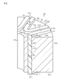
- the permanent magnet 23 of the present embodiment is made of a bonded magnet formed by molding and solidifying a magnet material in which magnet powder is mixed with a resin. That is, in the permanent magnet 23, the magnet accommodating hole 24 of the rotor core 22 is molded, and the magnet material before solidification is filled in the magnet accommodating hole 24 without a gap by injection molding, and is solidified in the magnet accommodating hole 24 after filling. It is configured. Therefore, the hole shape of the magnet accommodating hole 24 is the outer shape of the permanent magnet 23. Further, the permanent magnet 23 of the present embodiment is configured to partially protrude from the axial end faces 22c and 22d of the rotor core 22 (see FIG. 3 and the like).
- the permanent magnet 23 has an embedded magnet portion 23m in the magnet accommodating hole 24 and protruding portions 23x1, 23y1 protruding from the axial end faces 22c and 22d of the rotor core 22.
- a recess for forming the protruding portion 23x1,23y1 is provided in a molded mold (not shown) for closing the magnet accommodating holes 24 opened in the axial end faces 22c and 22d of the rotor core 22. It can be easily realized just by providing.
- a sumalium iron nitrogen (SmFeN) magnet is used, but other rare earth magnets or the like may be used.
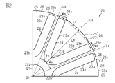
- the permanent magnet 23 has a substantially V-shaped folded shape that is convex inward in the radial direction. More specifically, as shown in FIG. 2, the permanent magnet 23 has a shape in which the radial inner ends of the pair of straight portions 23a are connected to each other by the bent portions 23b. The radial outer end portion 23c of the straight portion 23a is located near the outer peripheral surface 22a of the rotor core 22.
- the permanent magnet 23 has a constant thickness Wm in any of the V-shaped paths including the pair of straight portions 23a and the bent portions 23b.
- the permanent magnet 23 has a line-symmetrical shape with respect to its own circumferential center line Ls passing through the axis center O1 of the rotor 20, and is close to the magnetic pole boundary line Ld passing through the axis center O1 of the rotor 20 between adjacent permanent magnets 23. are doing.
- the angle between the adjacent magnetic pole boundary lines Ld, that is, the magnetic pole opening angle ⁇ m of the rotor magnetic pole portion 26 including the permanent magnet 23 is 180 ° in electrical angle.
- the distance between the intersection of the extension line of the inner surface of each straight line portion 23a of the V-shaped permanent magnet 23 and the outer peripheral surface 22a of the rotor core 22 is the magnetic pole pitch Lp
- the rotor core is on the circumferential center line Ls of the permanent magnet 23.
- the embedding depth is Lm from the outer peripheral surface 22a of 22 to the inner surface of the bent portion 23b.
- the permanent magnet 23 of the present embodiment is set to a deep folded shape so that the embedding depth Lm is larger than the magnetic pole pitch Lp. That is, the magnet surface 23d of the permanent magnet 23 of the present embodiment formed on each inner surface of each straight portion 23a and each bending portion 23b is set to be larger than the well-known surface magnet type magnet surface (not shown).
- the bent portion 23b of the permanent magnet 23 is located in the radial inward position close to the shaft fitting insertion hole 22b in which the rotating shaft 21 is fitted in the central portion of the rotor core 22. are doing.
- This folded shape of the permanent magnet 23 is an example, and can be appropriately changed, such as one having a shallow embedding depth Lm or a substantially U-shaped folded shape having a large bent portion 23b.
- the permanent magnet 23 is provided over the entire axial direction of the rotor core 22.
- the axial end faces 22c and 22d of the rotor core 22 are flat surfaces, and the permanent magnet 23 has protrusions 23x1, 23y1 that project axially from the axial end faces 22c and 22d of the rotor core 22.
- the protruding portions 23x1, 23y1 are continuous in a V-shaped path including the straight portion 23a and the bent portion 23b of the permanent magnet 23, and have a constant thickness Wm.
- the protrusions 23x1, 23y1 are provided on one axial end surface 22c of the rotor core 22 and the other axial end surface 22d, respectively.
- the protruding portions 23x1, 23y1 are continuously and integrally provided with the same material as the embedded magnet portion 23m of the permanent magnet 23 located in the magnet accommodating hole 24 of the rotor core 22.
- Such a protruding portion 23x1, 23y1 of the permanent magnet 23 is an end portion of the permanent magnet 23 located at the axial end faces 22c and 22d of the rotor core 22, and the leakage flux easily generated at the end portion of the permanent magnet 23 is shown in FIG. It functions to generate ⁇ b at this site.
- more magnetic flux of the embedded magnet portion 23m located in the rotor core 22 of the permanent magnet 23 is allowed to flow along the radial direction from the axial end faces 22c and 22d without leaking to the outside, and more magnetic flux is generated.
- the effective magnetic flux ⁇ a that contributes to the torque of the rotary electric machine M is set.
- the protrusions 23x1, 23y1 are set so that the amount of protrusion D1 is appropriate from the axial end faces 22c and 22d of the rotor core 22 while increasing the effective magnetic flux ⁇ a.
- the protrusion amount D1 of the protrusions 23x1, 23y1 may differ from the shown dimensions and the actual dimensions.
- the permanent magnet 23 mainly provided in the magnet accommodating hole 24 of the rotor core 22 is magnetized from the outside of the rotor core 22 so as to function as an original magnet by using a magnetizing device (not shown) after the magnet material is solidified.
- Eight permanent magnets 23 are provided in the circumferential direction of the rotor core 22 in the present embodiment, and are magnetized so as to be alternately different in the circumferential direction. Further, each permanent magnet 23 is magnetized in its own thickness direction.
- the portion of the rotor core 22 located inside the V-shaped folded shape of the permanent magnet 23 and radially outside the permanent magnet 23 functions as the outer core portion 25 for obtaining the reluctance torque facing the stator 10.
- the outer core portion 25 has a substantially triangular shape with one apex directed toward the center of the rotor 20 in the axial direction.
- the rotor 20 is configured as an 8-pole rotor magnetic pole portion 26 in the present embodiment including the permanent magnet 23 and the outer core portion 25 surrounded by the inside of the V-shape of the permanent magnet 23. As shown in FIG. 1, each rotor magnetic pole portion 26 functions as an N pole and an S pole alternately in the circumferential direction. In the rotor 20 having such a rotor magnetic pole portion 26, the magnet torque and the reluctance torque can be preferably obtained.
- the permanent magnet 23 embedded in the rotor core 22 protrudes from the axial end faces 22c and 22d on both sides of the rotor core 22 with the ends of the permanent magnets 23 as protrusions 23x1, 23y1 respectively. I'm letting you.
- the leakage flux ⁇ b generated at the end portion of the permanent magnet 23 is concentrated on the protruding portion 23x1,23y1.
- FIG. 5A is a comparison result between this embodiment and a comparative example.
- the ends of the permanent magnets 23 are projected from the axial end faces 22c and 22d on both sides of the rotor core 22 as protrusions 23x1, 23y1 respectively.
- a comparative example is a conventionally known configuration in which the end portion of the permanent magnet 23 is not projected from the axial end faces 22c and 22d of the rotor core 22.
- this embodiment is sufficiently larger than the comparative example. This is because the leakage flux ⁇ b is generated at the protruding portions 23x1, 23y1, so that most of the magnetic flux of the embedded magnet portion 23m of the permanent magnet 23 becomes the effective magnetic flux ⁇ a, and the effective magnetic flux ⁇ a increases.
- FIG. 5B the relationship between the protrusion amount D1 of the protrusion 23x1,23y1 and the induced voltage Vm is shown. However, it can be seen that the induced voltage Vm also rises.
- the induced voltage / magnet volume (Vm / Va) is smaller than that of the comparative example because the magnet volume Va increases by the amount of the protrusions 23x1, 23y1.
- the relationship between the protrusion amount D1 and the induced voltage / magnet volume (Vm / Va) is shown. Can be seen to gradually decrease.
- the protrusion amount D1 is appropriately set in consideration of the relationship between the protrusion amount D1 of the protrusions 23x1, 23y1 and the induced voltage Vm and the induced voltage / magnet volume (Vm / Va). Further, since a large protrusion amount D1 leads to an increase in the weight of the rotor 20 and an increase in the magnet material of the permanent magnet 23, it is also preferable to consider when setting the protrusion amount D1.
- the protruding portions 23x1, 23y1 of the permanent magnet 23 are continuous in a V-shaped path including the straight portion 23a and the bent portion 23b of the permanent magnet 23, and are constant in thickness Wm.
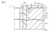
- FIGS. 7 and 8 a case in which the thickness Wm1 of the bent portion 23b of the permanent magnet 23 is narrower than the thickness Wm of the straight portion 23a is also examined.
- FIG. 9A is a comparison result between a form in which the bent portion 23b has a thickness of Wm1 and a slightly narrow width and a comparative example.
- this embodiment is larger than the comparative example.
- the bent portion 23b of the magnet 23 is a portion where the magnetic flux leaks less than that of the straight portion 23a, it is possible to adjust the thickness Wm1 of the bent portion 23b to be slightly narrower.
- the thickness Wm1 of the bent portion 23b of the permanent magnet 23 is appropriately changed so that both the Vm value and the Vm / Va value are larger than those in the comparative example.
- the relationship between the protrusion amount D1 of the protrusion 23x1,23y1 and the induced voltage Vm shown in FIG. 9B when the protrusion amount D1 of the protrusion 23x1,23y1 becomes zero or more, the effective magnetic flux ⁇ a increases. The Vm value increases, but in this embodiment, the change reaches a plateau early.
- the embedded magnet portion 23m of the permanent magnet 23 located in the rotor core 22 In order for the magnetic flux of the rotor core 22 to leak from the axial end faces 22c and 22d of the rotor core 22, the protrusion exceeds the protrusions 23x1,23y1. That is, since the path length at which the magnetic flux of the embedded magnet portion 23m tends to leak becomes long, it is possible to suppress the leakage of the magnetic flux of the embedded magnet portion 23m.
- the magnetic flux of the embedded magnet portion 23m of the permanent magnet 23 becomes an effective magnetic flux ⁇ a that contributes to the torque of the rotary electric machine M
- the magnetic flux amount of the effective magnetic flux ⁇ a is increased by preventing this from leaking as much as possible. It can be fully expected that the torque performance of M will be improved.
- the axial end faces 22c and 22d of the rotor core 22 have a general flat surface shape, and the end portion of the permanent magnet 23 can be realized by simply projecting from the axial end faces 22c and 22d of the rotor core 22. be able to.
- the protruding portions 23x1, 23y1 of the permanent magnet 23 are continuously provided in the extending direction of the V-shape of the permanent magnet 23 along the axial end faces 22c and 22d of the rotor core 22, they are embedded to contribute to the torque. Leakage of the magnetic flux of the magnet portion 23m can be more reliably suppressed over the entire permanent magnet 23.
- the protruding portions 23x1, 23y1 of the permanent magnet 23 are provided so that the amount of protrusion D1 from the axial end faces 22c and 22d of the rotor core 22 is constant, so that the magnetic flux of the embedded magnet portion 23m that contributes to torque is increased. Leakage can be similarly suppressed at each location.
- the protruding portions 23x1, 23y1 of the permanent magnet 23 are continuously and integrally provided from the embedded magnet portion 23m of the rotor core 22, they can be easily formed by using the same material at the same time.
- the configuration of the protruding portions 23x1, 23y1 at the ends of the permanent magnets 23 protruding from the axial end faces 22c and 22d of the rotor core 22 may be appropriately changed.
- a protruding portion may be partially provided in a V-shaped path including a straight portion 23a and a bent portion 23b of the permanent magnet 23.
- a protruding portion 23x2, 23y2 that protrudes only from the bent portion 23b of the permanent magnet 23 may be provided.
- the protrusions 23x2 and 23y2 are similarly provided on both the axial end faces 22c and 22d of the rotor core 22.
- a protruding portion 23x3, 23y3 that protrudes only from the straight portion 23a of the permanent magnet 23 may be provided.
- the protrusions 23x3 and 23y3 are similarly provided on both the axial end faces 22c and 22d of the rotor core 22.
- a protruding portion 23x2, 23y2 protruding from the bent portion 23b of the permanent magnet 23 and a protruding portion 23x4, 23y4 partially protruding in the extending direction of the straight line portion 23a may be provided.
- the protrusions 23x2, 23y2 and the protrusions 23x4, 23y4 are similarly provided on both the axial end faces 22c and 22d of the rotor core 22.
- the protruding portion of the permanent magnet 23 may be provided on only one side of the V-shape, such as a straight portion 23a on one side of the V-shape of the permanent magnet 23 and half of the bent portion 23b.
- the magnet material of the permanent magnet 23 can be reduced, and the effect of reducing the weight of the rotor 20 can be expected.
- each of the axial end faces 22c and 22d of the rotor core 22 may be provided with protrusions having different configurations. Among them, the mode in which the protruding portion is provided only on one side of the axial end faces 22c and 22d of the rotor core 22 is listed first.
- the protrusion 23x1 may be provided only on the axial end surface 22c side of the rotor core 22. As described above, the protruding portion 23x1 is continuous along the V-shaped path of the permanent magnet 23.
- a protruding portion 23x2 that protrudes only from the bent portion 23b of the permanent magnet 23 may be provided only on the axial end surface 22c side of the rotor core 22.
- a protruding portion 23x3 that protrudes only from the linear portion 23a of the permanent magnet 23 may be provided only on the axial end surface 22c side of the rotor core 22.
- the protruding portion 23x2 protruding from the bent portion 23b of the permanent magnet 23 and the protruding portion 23x4 partially protruding in the extending direction of the straight portion 23a are provided. It may be provided.
- the magnet material of the permanent magnet 23 can be reduced, and the effect of reducing the weight of the rotor 20 can be expected.
- a protruding portion 23x2 is provided that protrudes only by the bent portion 23b of the permanent magnet 23, and on the axial end surface 22d side of the rotor core 22, the bent portion of the permanent magnet 23 is provided.
- a protruding portion 23y2 protruding from the 23b and a protruding portion 23y4 partially protruding in the extending direction of the straight portion 23a may be provided.
- a continuous protrusion 23x1 is provided along the V-shaped path of the permanent magnet 23, and on the axial end surface 22d side of the rotor core 22, a straight line of the permanent magnet 23 is provided.
- a protruding portion 23y3 that protrudes only from the portion 23a may be provided.
- a protruding portion 23x2 protruding from the bent portion 23b of the permanent magnet 23 and a protruding portion 23x4 partially protruding in the extending direction of the straight portion 23a are provided on the axial end surface 22d side of the rotor core 22 .
- a continuous protrusion 23y1 may be provided along the V-shaped path of the permanent magnet 23.
- the protruding portion may be partially provided in the thickness direction orthogonal to the extending direction of the V-shaped path of the permanent magnet 23.
- a protruding portion 23x5, 23y5 having a narrow shape may be provided at the central portion in the thickness direction of the permanent magnet 23.
- the protrusions 23x5 and 23y5 are continuous along the V-shaped path of the permanent magnet 23. Further, the protrusions 23x5 and 23y5 are similarly provided on both the axial end faces 22c and 22d of the rotor core 22.
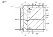
- a protruding portion 23x6, 23y6 having a groove portion 23z1 may be provided at the central portion in the thickness direction of the permanent magnet 23.
- the groove portion 23z1 has the same depth as the protrusion amount D1 of the protrusions 23x6, 23y6.
- the protrusions 23x6, 23y6 are continuous along the V-shaped path of the permanent magnet 23. Further, the protrusions 23x6, 23y6 are similarly provided on both the axial end faces 22c and 22d of the rotor core 22.
- the depth of the groove portion 23z2 provided in the central portion of the protruding portion 23x6, 23y6 of the permanent magnet 23 in the thickness direction may be different from the protruding amount D1 of the protruding portion 23x6, 23y6.
- the groove portion 23z2 may be shallower or deeper than the protrusion amount D1 of the protrusions 23x6, 23y6 as shown in FIG. 22.
- the magnet material of the permanent magnet 23 can be reduced, and the effect of reducing the weight of the rotor 20 can be expected.
- the shape of the protruding portion provided on the permanent magnet 23 may be changed.
- the protrusion amount D1 may be changed depending on the portion of the protrusion.
- the protruding portions 23x7, 23y7 provided in the bent portion 23b of the permanent magnet 23 may have a slope shape.
- the protrusions 23x7 and 23y7 are formed in a slope shape in which the inside of the V-shape of the permanent magnet 23 is high and the outside is low.
- the protrusions 23x7 and 23y7 are similarly provided on both the axial end faces 22c and 22d of the rotor core 22.
- protrusions 23x8, 23y8 that are continuous in the extending direction of the V-shaped path of the permanent magnet 23, the bent portion 23b is the highest, and the radial outer end portion 23c of the straight portion 23a is reached. It may be a slope shape that gradually becomes lower toward the bottom.
- the protrusions 23x8 and 23y8 are similarly provided on both the axial end faces 22c and 22d of the rotor core 22.
- the magnet material of the permanent magnet 23 can be reduced, and the effect of reducing the weight of the rotor 20 can be expected. Further, it is expected that the degree of freedom of the outer shape of the rotor 20 including the protruding shape of the permanent magnet 23 can be increased.
- the protruding portion of the permanent magnet 23 may be separated from the embedded magnet portion 23 m.
- the magnet materials may be different from each other.
- the protruding portions 23x9, 23y9 of the permanent magnet 23 are continuous in the extending direction of the V-shaped path, and are similarly provided on both the axial end faces 22c and 22d of the rotor core 22.
- the protruding portions 23x9 and 23y9 may use a magnet material that is cheaper than the embedded magnet portion 23m. Further, the protruding portions 23x9 and 23y9 may use a magnet material having a magnetic force different from that of the embedded magnet portion 23m.
- the protruding portions 23x9 and 23y9 may be made of a magnet material having a strength different from that of the embedded magnet portion 23m, and may be configured to have high strength in consideration of being exposed from the axial end faces 22c and 22d of the rotor core 22. .. Further, the protruding portions 23x9 and 23y9 may be formed at the same time as the embedded magnet portion 23m, or may be retrofitted.
- a protrusion 23x1 may be selectively provided in every other permanent magnet 23 arranged in the circumferential direction. In addition, it may be placed at equal intervals other than every other one, or it may be placed at unequal intervals.
- the magnet material of the permanent magnet 23 can be reduced, and the effect of reducing the weight of the rotor 20 can be expected.
- the recess 24a in which the margin of the magnet material is accumulated when the permanent magnet 23 including the protrusions 23x1, 23y1 is formed is formed in the magnet accommodating hole 24. It may be provided around the opening. By doing so, since the margin of the magnet material can be accommodated in the recess 24a, it is possible to suppress the protrusion of the permanent magnet 23 as a burr on the axial end faces 22c and 22d of the rotor core 22.
- the permanent magnet 23 is not limited to a V-shape, but may have another folded shape that is convex inward in the radial direction of the rotor 20, such as a U-shape. Further, it may have a shape other than the folded shape such as an I shape.
- a permanent magnet 23 is formed by injection molding a magnet material into the magnet accommodating hole 24 of the rotor core 22. However, the permanent magnet 23 is prepared in advance and inserted into the magnet accommodating hole 24 of the rotor core 22 to be fixed. You may.
- the configuration of the rotor 20 and the configuration of the rotary electric machine M may be changed as appropriate.
- FIG. 28 is a graph comparing the magnitudes of the induced voltage Vm generated in the rotary electric machine M in the comparative configuration 1, the comparative configuration 2, and the above embodiment.
- the axial length of the stator core 11 is set to be equal to the axial length of the rotor core 22.
- the axial length of the stator core 11 is, for example, the axial length of the tip surface 12a of the teeth 12.
- the protruding portion 23x1,23y1 is formed by forming the permanent magnet 23 in the axial direction longer than the axial length of the rotor core 22. That is, in the above embodiment, the axial length of the permanent magnet 23 is longer than the axial length of the rotor core 22 and the stator core 11.
- the protruding portions 23x1, 23y1 of the permanent magnet 23 are located laterally in the axial direction with respect to both end faces in the axial direction of the stator core 11.
- the comparative configuration 1 has a configuration in which the axial lengths of the permanent magnet 23, the rotor core 22, and the stator core 11 are equal to each other.
- the axial length of the permanent magnet 23 is set equal to the axial length of the rotor core 22. That is, in the comparative configuration 2, a portion where the permanent magnet 23 protrudes in the axial direction from the magnet accommodating hole 24 is not formed. Further, in the comparative configuration 2, the axial lengths of the rotor core 22 and the permanent magnet 23 are set longer than the axial length of the stator core 11.
- the induced voltage Vm is larger in the comparative configuration 2 and the above embodiment than in the comparative configuration 1. It is considered that this is because the entire axial direction of the stator core 11 is included in the axial range of the permanent magnet 23.
- the magnitudes of the induced voltage Vm are almost the same.
- the axial length of the rotor core 22 is equal to the axial length of the stator core 11, and the axial length of only the permanent magnet 23 is increased. Therefore, in the above embodiment, the axial length of the rotor core 22 can be shortened with respect to the comparative configuration 2. Therefore, as in the above embodiment, by forming the axial length of the permanent magnet 23 longer than the axial length of the rotor core 22 and the stator core 11, the induced voltage Vm is improved, and the weight of the rotor core 22 and thus the rotary electric machine M is reduced. Can contribute to the conversion.
- the rotor core 22 is composed of a single component, but in addition to this, for example, the rotor core 22 may be configured by a plurality of rotor core portions arranged side by side in the axial direction.
- the rotor core 22 is configured by two rotor core portions arranged side by side in the axial direction.
- one of the two rotor core portions will be referred to as a first rotor core portion 31, and the other will be referred to as a second rotor core portion 32.
- the same configurations as those in the above embodiment may be designated by the same reference numerals as those in the above embodiment, and detailed description thereof may be omitted.
- the rotor 20 includes a rotating shaft 21, a first rotor portion R1 having a first rotor core portion 31, and a second rotor portion R2 having a second rotor core portion 32.
- the first rotor portion R1 and the second rotor portion R2 are arranged side by side in the direction along the axis L1 of the rotor 20.
- the first rotor portion R1 and the second rotor portion R2 are configured to be integrally rotatable with the rotating shaft 21.
- the first rotor portion R1 and the second rotor portion R2 are rotatably arranged with respect to the stator 10 by supporting the rotating shaft 21 with a bearing (not shown) provided in the housing 14.
- the first rotor core portion 31 has a substantially cylindrical shape in which the rotating shaft 21 is inserted into the central portion.
- the second rotor core portion 32 also has a substantially cylindrical shape in which the rotating shaft 21 is fitted into the central portion.
- the first rotor portion R1 includes a permanent magnet 23 embedded in the first rotor core portion 31.
- the second rotor portion R2 includes a permanent magnet 23 embedded in the second rotor core portion 32.
- the first rotor core portion 31 and the second rotor core portion 32 are, for example, parts having the same structure.
- Each of the first rotor core portion 31 and the second rotor core portion 32 is made of a magnetic metal material.
- Each of the first rotor core portion 31 and the second rotor core portion 32 is configured by, for example, laminating a plurality of electromagnetic steel sheets in the axis L1 direction.
- the first rotor core portion 31 and the second rotor core portion 32 are arranged side by side in the axial direction to form the rotor core 22.
- the cross-sectional shape orthogonal to the axis L1 is, for example, the same as the cross-sectional shape orthogonal to the axis L1 in the rotor core 22 of the above embodiment. That is, the first rotor core portion 31 and the second rotor core portion 32 each have a magnet accommodating hole 24 for accommodating the permanent magnet 23.
- the configuration such as the number and shape of the magnet accommodating holes 24 in the circumferential direction is the same as, for example, the magnet accommodating holes 24 of the above embodiment.
- each of the first rotor core portion 31 and the second rotor core portion 32 the portion located inside the V-shaped folded shape of the permanent magnet 23 and radially outside the permanent magnet 23 is opposed to the stator 10 and has a reluctance torque. Functions as the outer core portion 25 for obtaining.
- Each of the first rotor portion R1 and the second rotor portion R2 has eight rotor magnetic pole portions 26 including a permanent magnet 23 and an outer core portion 25. The rotor magnetic poles 26 alternately function as N poles and S poles in the circumferential direction.
- each rotor magnetic pole portion 26 has a magnetic pole center C in the circumferential direction.
- the magnetic pole centers C are set at equal intervals from each other in the circumferential direction.
- the magnetic pole centers C of each of the eight rotor magnetic pole portions 26 are set at intervals of 45 ° in the circumferential direction.
- the magnetic pole center C coincides with the circumferential center line Ls of the permanent magnet 23.
- the rotor magnetic pole portion 26 of the second rotor portion R2 is displaced in the circumferential direction with respect to the rotor magnetic pole portion 26 of the first rotor portion R1.
- the first rotor portion R1 and the second rotor portion R2 have the same configuration as each other, and the second rotor portion R2 is rotated by a predetermined angle with respect to the first rotor portion R1 to form a rotor 20.
- the magnetic pole center C of the second rotor portion R2 is displaced by a predetermined angle in the circumferential direction with respect to the magnetic pole center C of the first rotor portion R1.
- the deviation angle of the second rotor portion R2 with respect to the magnetic pole center C of the first rotor portion R1 in the circumferential direction is referred to as a skew angle ⁇ .
- the skew angle ⁇ in this example is set based on the following equation (a), where p is the number of poles of the rotor 20, and L is the least common multiple of the number of poles p and the number of slots of the stator 10.
- FIG. 30 shows the relationship between the rotation angle of the rotor 20 and the magnitude of the cogging torque in the configuration in which the skew angle ⁇ is set to 7.5 [°].
- the cogging torque generated in the first rotor portion R1 is T1
- the cogging torque generated in the second rotor portion R2 is T2
- the combined cogging torque generated in the entire rotor 20 in which the cogging torques T1 and T2 are combined is T3.
- the skew angle ⁇ is 7.5 [°]
- the cogging torque T1 and the cogging torque T2 are in opposite phases to each other.
- the cogging torques T1 and T2 are canceled out, whereby the combined cogging torque T3 is reduced.
- the combined cogging torque T3 of the entire rotor 20 can be reduced.
- the value of the skew angle ⁇ in this example is an example, and the value of the skew angle ⁇ can be appropriately changed according to the configuration of the rotary electric machine M.
- the rotor 20 of this example also has a protruding portion 23x1,23y1 which is a portion of a permanent magnet 23 protruding in the axial direction from the rotor core 22.
- the protruding portion 23x1 protrudes from one axial end surface 22c of the rotor core 22.
- the axial end surface 22c of the rotor core 22 is the end surface of the first rotor core portion 31 opposite to the second rotor portion R2.
- the protruding portion 23x1 is a part of the permanent magnet 23 of the first rotor portion R1.
- the protruding portion 23y1 protrudes from the other axial end surface 22d of the rotor core 22.
- the axial end surface 22d of the rotor core 22 is the end surface of the second rotor core portion 32 opposite to the first rotor portion R1.
- the protruding portion 23y1 is a part of the permanent magnet 23 of the second rotor portion R2.
- the permanent magnet 23 does not project from the axial end face on the opposite side of the axial end face 22c where the protruding portion 23x1 is provided.
- the permanent magnet 23 does not protrude from the axial end face on the side opposite to the axial end face 22d where the protruding portion 23y1 is provided.
- the first rotor core portion 31 and the second rotor core portion 32 are arranged side by side in such a manner that the end faces in the axial direction in which the permanent magnets 23 do not project are opposed to each other in the axial direction.
- the first rotor core portion 31 and the second rotor core portion 32 are arranged side by side so that the axial end faces are in contact with each other.
- the axial end faces of the permanent magnets 23 are not projected, and the axial end faces are in contact with each other.
- a gap may be provided in the.
- the permanent magnet 23 may be configured so as to project from the axial end faces of the first rotor core portion 31 and the second rotor core portion 32 facing each other.
- M rotary electric machine 10 stator, 20 rotor, 22 rotor core, 22c, 22d axial end face, 23 permanent magnet, 23m embedded magnet part, 23x1-23x9, 23y1-23y9 protrusion, 24 magnet accommodation hole, D1 protrusion amount, R1 1st rotor part (rotor part), R2 2nd rotor part (rotor part), 31 1st rotor core part (rotor core part), 32 2nd rotor core part (rotor core part), C magnetic pole center.
Landscapes
- Engineering & Computer Science (AREA)
- Power Engineering (AREA)
- Permanent Field Magnets Of Synchronous Machinery (AREA)
Abstract
The present invention is configured so that end parts of a permanent magnet (23) protrude, as projecting parts (23x1, 23y1), from axial end faces (22c, 22d) which form flat surfaces of a rotor core 22, and leakage of the magnetic flux of an embedded magnet part (23m) of the permanent magnet (23), which is positioned inside the rotor core (22), from the axial end faces (22c, 22d) of the rotor core (22) is minimized as much as possible.
Description
本発明は、埋込磁石型のロータ及び回転電機に関する。
The present invention relates to an embedded magnet type rotor and a rotary electric machine.
埋込磁石型(IPM型)のロータを用いる回転電機が周知である。埋込磁石型のロータは、永久磁石がロータコアの内部に埋め込まれる態様をなし、永久磁石によるマグネットトルクに加えて、永久磁石より径方向外側に位置する外側コア部にてリラクタンストルクを得る構成となっている。このような埋込磁石型のロータにおいては、永久磁石の配置態様等の関係でロータコアの軸方向端面に位置する永久磁石の端部において漏れ磁束が生じ易く、特に有効磁束分が漏れるとトルク性能の低下に繋がるため、その対策について従来種々の提案がなされている(例えば特許文献1参照)。
A rotary electric machine that uses an embedded magnet type (IPM type) rotor is well known. The embedded magnet type rotor has a configuration in which a permanent magnet is embedded inside the rotor core, and in addition to the magnet torque generated by the permanent magnet, a reluctance torque is obtained at the outer core portion located radially outside the permanent magnet. It has become. In such an embedded magnet type rotor, leakage flux is likely to occur at the end of the permanent magnet located on the axial end face of the rotor core due to the arrangement of the permanent magnets, etc., and torque performance is particularly high when the effective magnetic flux leaks. Since it leads to a decrease in the amount of magnetic flux, various proposals have been made in the past regarding countermeasures (see, for example, Patent Document 1).
上記特許文献1等の対策は、ロータコアの端面形状を一般的な平坦面から比較的大きな段差を構成する等、形状変更の必要があるため、ロータコアの製造が煩雑になることが懸念される。本発明者は、上記対策での懸念事項を踏まえ、別の簡易な対応で永久磁石の有効磁束分の漏れを抑制できないか模索していた。本発明の目的は、簡易な対応で永久磁石の有効磁束分の漏れを抑制し、トルク性能の向上が期待できるロータ及び回転電機を提供することにある。
As a measure such as Patent Document 1 above, it is necessary to change the shape of the end face of the rotor core, such as forming a relatively large step from a general flat surface, so that there is a concern that the manufacture of the rotor core becomes complicated. Based on the concerns in the above measures, the present inventor has sought to suppress the leakage of the effective magnetic flux of the permanent magnet by another simple measure. An object of the present invention is to provide a rotor and a rotary electric machine which can be expected to improve torque performance by suppressing leakage of an effective magnetic flux of a permanent magnet with a simple response.
上記課題を解決するロータは、ロータコア(22)の磁石収容孔(24)に埋込態様をなす永久磁石(23)を有するロータ(20)であって、前記ロータコアの軸方向端面(22c,22d)は、平坦面をなしており、前記永久磁石は、前記ロータコアの軸方向端面から少なくとも一部が突出する突出部(23x1~23x9,23y1~23y9)を有して構成された。
The rotor that solves the above problems is a rotor (20) having a permanent magnet (23) embedded in a magnet accommodating hole (24) of the rotor core (22), and is an axial end surface (22c, 22d) of the rotor core. ) Form a flat surface, and the permanent magnet is configured to have a protruding portion (23x1 to 23x9, 23y1 to 23y9) having at least a part protruding from the axial end surface of the rotor core.
上記課題を解決する回転電機は、ロータコア(22)の磁石収容孔(24)に埋込態様をなす永久磁石(23)を有するロータ(20)と、前記ロータに対して回転磁界を付与するステータ(10)とを備えた回転電機(M)であって、前記ロータコアの軸方向端面(22c,22d)は、平坦面をなしており、前記永久磁石は、前記ロータコアの軸方向端面から少なくとも一部が突出する突出部(23x1~23x9,23y1~23y9)を有して前記ロータが構成された。
Rotating electric machines that solve the above problems include a rotor (20) having a permanent magnet (23) embedded in a magnet accommodating hole (24) of the rotor core (22) and a stator that applies a rotating magnetic field to the rotor. In the rotary electric machine (M) provided with (10), the axial end faces (22c, 22d) of the rotor core have a flat surface, and the permanent magnet is at least one from the axial end face of the rotor core. The rotor was configured with protruding portions (23x1 to 23x9, 23y1 to 23y9) having protruding portions.
上記ロータ及び回転電機によれば、ロータコアの平坦面をなす軸方向端面から永久磁石の少なくとも一部が突出部として突出しているため、ロータコア内に位置する永久磁石の埋込磁石部分の磁束がロータコアの軸方向端面から漏れ出ようとするにはその突出部を越える態様となる。つまり、埋込磁石部分の磁束の漏れ出ようとする経路長が長くなるため、埋込磁石部分の磁束の漏れが抑制される。永久磁石の埋込磁石部分の磁束は回転電機のトルクに寄与する有効磁束となるため、これを極力漏れ出ないようにして有効磁束の磁束量を増加させることで、回転電機のトルク性能の向上が期待できる。しかも、ロータコアの軸方向端面は一般的な平坦面形状であり、永久磁石の端部をそのロータコアの軸方向端面から突出させるだけの簡易な対応にて実現可能である。
According to the rotor and the rotary electric machine, since at least a part of the permanent magnet protrudes as a protruding portion from the axial end surface forming the flat surface of the rotor core, the magnetic flux of the embedded magnet portion of the permanent magnet located in the rotor core is the rotor core. In order to leak from the axial end face of the magnet, the protrusion is crossed. That is, since the path length at which the magnetic flux of the embedded magnet portion tries to leak becomes long, the leakage of the magnetic flux of the embedded magnet portion is suppressed. Since the magnetic flux of the embedded magnet part of the permanent magnet becomes an effective magnetic flux that contributes to the torque of the rotating electric machine, the torque performance of the rotating electric machine is improved by increasing the amount of magnetic flux of the effective magnetic flux by preventing this from leaking as much as possible. Can be expected. Moreover, the axial end face of the rotor core has a general flat surface shape, and it can be realized by simply projecting the end portion of the permanent magnet from the axial end face of the rotor core.
以下、ロータの製造装置、ロータの製造方法及びロータの一実施形態を説明する。
Hereinafter, the rotor manufacturing apparatus, the rotor manufacturing method, and one embodiment of the rotor will be described.
図1に示す本実施形態の回転電機Mは、埋込磁石型のブラシレスモータにて構成されている。回転電機Mは、略円環状のステータ10と、ステータ10の径方向内側空間にて回転可能に配置される略円柱状のロータ20とを備えている。
The rotary electric machine M of the present embodiment shown in FIG. 1 is composed of an embedded magnet type brushless motor. The rotary electric machine M includes a substantially annular stator 10 and a substantially cylindrical rotor 20 rotatably arranged in the radial inner space of the stator 10.
ステータ10は、略円環状のステータコア11を備えている。ステータコア11は、磁性金属材料にて構成されている。ステータコア11は、例えば複数枚の電磁鋼板を軸線L1方向(図3参照)に積層して構成されている。ステータコア11は、径方向内側に向かって延び周方向等間隔に配置される本実施形態では12個のティース12を有している。各ティース12は、互いに同一形状をなしている。ティース12は、先端部である径方向内側端部が略T型をなし、先端面12aがロータ20の外周面に倣った円弧状をなしている。ティース12には、巻線13が集中巻きにて巻装されている。巻線13は3相結線がなされ、図1ようにそれぞれU相、V相、W相として機能する。そして、巻線13に対して電源供給がなされると、ロータ20を回転駆動するための回転磁界がステータ10にて生じるようになっている。このようなステータ10は、ステータコア11の外周面がハウジング14の内周面に対して固定されている。
The stator 10 includes a substantially annular stator core 11. The stator core 11 is made of a magnetic metal material. The stator core 11 is configured, for example, by laminating a plurality of electromagnetic steel sheets in the L1 direction of the axis (see FIG. 3). The stator core 11 has 12 teeth 12 in the present embodiment extending inward in the radial direction and arranged at equal intervals in the circumferential direction. Each tooth 12 has the same shape as each other. In the teeth 12, the radial inner end portion, which is the tip portion, has a substantially T shape, and the tip surface 12a has an arc shape following the outer peripheral surface of the rotor 20. The winding 13 is wound around the teeth 12 by centralized winding. The winding 13 is connected in three phases and functions as a U phase, a V phase, and a W phase, respectively, as shown in FIG. Then, when power is supplied to the winding 13, a rotating magnetic field for rotationally driving the rotor 20 is generated in the stator 10. In such a stator 10, the outer peripheral surface of the stator core 11 is fixed to the inner peripheral surface of the housing 14.
ロータ20は、回転軸21と、回転軸21が中心部に嵌挿される略円柱状のロータコア22と、ロータコア22の内部に埋め込まれる態様をなす本実施形態では8個の永久磁石23とを備えている。ロータコア22は、磁性金属材料にて構成されている。ロータコア22は、例えば複数枚の電磁鋼板を図3にて示す軸線L1方向に積層して構成されている。ロータ20は、回転軸21がハウジング14に設けられる図示略の軸受に支持されることで、ステータ10に対して回転可能に配置されている。
The rotor 20 includes a rotary shaft 21, a substantially columnar rotor core 22 into which the rotary shaft 21 is fitted in a central portion, and eight permanent magnets 23 in the present embodiment in which the rotary shaft 21 is embedded inside the rotor core 22. ing. The rotor core 22 is made of a magnetic metal material. The rotor core 22 is configured, for example, by laminating a plurality of electromagnetic steel sheets in the direction of the axis L1 shown in FIG. The rotor 20 is rotatably arranged with respect to the stator 10 by supporting the rotating shaft 21 with a bearing (not shown) provided in the housing 14.
ロータコア22は、永久磁石23を収容するための磁石収容孔24を有している。磁石収容孔24は、ロータコア22の周方向等間隔に本実施形態では8個設けられている。各磁石収容孔24は、径方向内側に向かって凸の略V字の折返し形状をなし、互いに同一形状をなしている。また、磁石収容孔24は、ロータコア22の軸方向全体に亘り設けられている。
The rotor core 22 has a magnet accommodating hole 24 for accommodating the permanent magnet 23. Eight magnet accommodating holes 24 are provided in the present embodiment at equal intervals in the circumferential direction of the rotor core 22. Each magnet accommodating hole 24 has a substantially V-shaped folded shape that is convex inward in the radial direction, and has the same shape as each other. Further, the magnet accommodating hole 24 is provided over the entire axial direction of the rotor core 22.
ここで、本実施形態の永久磁石23は、磁石粉体を樹脂と混合した磁石材料を成型固化してなるボンド磁石よりなる。すなわち、永久磁石23は、ロータコア22の磁石収容孔24を成形型とし、固化前の磁石材料が射出成形により磁石収容孔24内に隙間なく充填され、充填後に磁石収容孔24内で固化されて構成されている。したがって、磁石収容孔24の孔形状は、永久磁石23の外形形状となる。また、本実施形態の永久磁石23は、ロータコア22の軸方向端面22c,22dから一部突出させて構成されている(図3等参照)。永久磁石23は、磁石収容孔24内にある埋込磁石部23mと、ロータコア22の軸方向端面22c,22dから突出する突出部23x1,23y1とを有する。この永久磁石23の突出部23x1,23y1については、ロータコア22の軸方向端面22c,22dに開口する磁石収容孔24を閉塞するための図示略の成形型に、突出部23x1,23y1形成用の凹部を設けるだけで容易に実現可能である。本実施形態の永久磁石23に用いられる磁石粉体としては、例えばサマリウム鉄窒素(SmFeN)系磁石が用いられるが、他の希土類磁石等を用いてもよい。
Here, the permanent magnet 23 of the present embodiment is made of a bonded magnet formed by molding and solidifying a magnet material in which magnet powder is mixed with a resin. That is, in the permanent magnet 23, the magnet accommodating hole 24 of the rotor core 22 is molded, and the magnet material before solidification is filled in the magnet accommodating hole 24 without a gap by injection molding, and is solidified in the magnet accommodating hole 24 after filling. It is configured. Therefore, the hole shape of the magnet accommodating hole 24 is the outer shape of the permanent magnet 23. Further, the permanent magnet 23 of the present embodiment is configured to partially protrude from the axial end faces 22c and 22d of the rotor core 22 (see FIG. 3 and the like). The permanent magnet 23 has an embedded magnet portion 23m in the magnet accommodating hole 24 and protruding portions 23x1, 23y1 protruding from the axial end faces 22c and 22d of the rotor core 22. Regarding the protruding portions 23x1,23y1 of the permanent magnet 23, a recess for forming the protruding portion 23x1,23y1 is provided in a molded mold (not shown) for closing the magnet accommodating holes 24 opened in the axial end faces 22c and 22d of the rotor core 22. It can be easily realized just by providing. As the magnet powder used for the permanent magnet 23 of the present embodiment, for example, a sumalium iron nitrogen (SmFeN) magnet is used, but other rare earth magnets or the like may be used.
永久磁石23は、径方向内側に向かって凸の略V字の折返し形状をなしている。詳述すると、永久磁石23は、図2に示すように、一対の直線部23aの径方向内側端部同士を屈曲部23bにて繋いだ形状をなしている。直線部23aの径方向外側端部23cは、ロータコア22の外周面22aの近くに位置している。永久磁石23は、一対の直線部23a及び屈曲部23bを含むV字経路のいずれにおいても厚さWmが一定に設定されている。永久磁石23は、ロータ20の軸中心O1を通る自身の周方向中心線Lsに対して線対称形状をなし、隣接の永久磁石23間におけるロータ20の軸中心O1を通る磁極境界線Ldに近接している。隣接の磁極境界線Ld間の角度、すなわちこの永久磁石23を含むロータ磁極部26の磁極開角度θmは、電気角で180°である。
The permanent magnet 23 has a substantially V-shaped folded shape that is convex inward in the radial direction. More specifically, as shown in FIG. 2, the permanent magnet 23 has a shape in which the radial inner ends of the pair of straight portions 23a are connected to each other by the bent portions 23b. The radial outer end portion 23c of the straight portion 23a is located near the outer peripheral surface 22a of the rotor core 22. The permanent magnet 23 has a constant thickness Wm in any of the V-shaped paths including the pair of straight portions 23a and the bent portions 23b. The permanent magnet 23 has a line-symmetrical shape with respect to its own circumferential center line Ls passing through the axis center O1 of the rotor 20, and is close to the magnetic pole boundary line Ld passing through the axis center O1 of the rotor 20 between adjacent permanent magnets 23. are doing. The angle between the adjacent magnetic pole boundary lines Ld, that is, the magnetic pole opening angle θm of the rotor magnetic pole portion 26 including the permanent magnet 23 is 180 ° in electrical angle.
ここで、V字形状をなす永久磁石23の各直線部23aの内側面の延長線とロータコア22の外周面22aとの交点間を磁極ピッチLp、永久磁石23の周方向中心線Ls上でロータコア22の外周面22aから屈曲部23bの内側面までを埋込深さLmとする。本実施形態の永久磁石23は、磁極ピッチLpより埋込深さLmが大となるような深い折返し形状に設定されている。つまり、各直線部23a及び屈曲部23bの各内側面でなす本実施形態の永久磁石23の磁石表面23dが、周知の表面磁石型の磁石表面(図示略)よりも大きくなるような設定としている。また、埋込深さLmが大きい設定としていることで、永久磁石23の屈曲部23bは、ロータコア22の中心部の回転軸21の嵌挿される軸嵌挿孔22bに近い径方向内側寄りに位置している。なお、永久磁石23のこの折返し形状は一例であり、埋込深さLmが浅いものや屈曲部23bの大きい略U字の折返し形状のもの等、適宜変更可である。
Here, the distance between the intersection of the extension line of the inner surface of each straight line portion 23a of the V-shaped permanent magnet 23 and the outer peripheral surface 22a of the rotor core 22 is the magnetic pole pitch Lp, and the rotor core is on the circumferential center line Ls of the permanent magnet 23. The embedding depth is Lm from the outer peripheral surface 22a of 22 to the inner surface of the bent portion 23b. The permanent magnet 23 of the present embodiment is set to a deep folded shape so that the embedding depth Lm is larger than the magnetic pole pitch Lp. That is, the magnet surface 23d of the permanent magnet 23 of the present embodiment formed on each inner surface of each straight portion 23a and each bending portion 23b is set to be larger than the well-known surface magnet type magnet surface (not shown). .. Further, since the embedding depth Lm is set to be large, the bent portion 23b of the permanent magnet 23 is located in the radial inward position close to the shaft fitting insertion hole 22b in which the rotating shaft 21 is fitted in the central portion of the rotor core 22. are doing. This folded shape of the permanent magnet 23 is an example, and can be appropriately changed, such as one having a shallow embedding depth Lm or a substantially U-shaped folded shape having a large bent portion 23b.
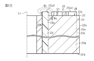
また、永久磁石23は、図3及び図4に示すように、ロータコア22の軸方向全体に亘り設けられている。ロータコア22の軸方向端面22c,22dは平坦面をなしており、永久磁石23はそのロータコア22の軸方向端面22c,22dから軸方向に突出する突出部23x1,23y1を有している。突出部23x1,23y1は、永久磁石23の直線部23a及び屈曲部23bを含むV字経路で連続し厚さWmが一定である。突出部23x1,23y1は、ロータコア22の一方の軸方向端面22cと他方の軸方向端面22dとのそれぞれに設けられている。突出部23x1,23y1は、ロータコア22の磁石収容孔24内に位置する永久磁石23の埋込磁石部23mと同種材料で連続して一体的に設けられている。
Further, as shown in FIGS. 3 and 4, the permanent magnet 23 is provided over the entire axial direction of the rotor core 22. The axial end faces 22c and 22d of the rotor core 22 are flat surfaces, and the permanent magnet 23 has protrusions 23x1, 23y1 that project axially from the axial end faces 22c and 22d of the rotor core 22. The protruding portions 23x1, 23y1 are continuous in a V-shaped path including the straight portion 23a and the bent portion 23b of the permanent magnet 23, and have a constant thickness Wm. The protrusions 23x1, 23y1 are provided on one axial end surface 22c of the rotor core 22 and the other axial end surface 22d, respectively. The protruding portions 23x1, 23y1 are continuously and integrally provided with the same material as the embedded magnet portion 23m of the permanent magnet 23 located in the magnet accommodating hole 24 of the rotor core 22.
このような永久磁石23の突出部23x1,23y1は、ロータコア22の軸方向端面22c,22dに位置する永久磁石23の端部であり、永久磁石23の端部で生じ易い図3に示す漏れ磁束φbをこの部位にて生じさせるように機能する。換言すると、永久磁石23のロータコア22内に位置する埋込磁石部23mの磁束のより多くを軸方向端面22c,22dから外部に漏らすことなく径方向に沿って流れるようにし、より多くの磁束が回転電機Mのトルクに寄与する有効磁束φaとなるようにしている。突出部23x1,23y1は、有効磁束φaの増加を図りつつ、ロータコア22の軸方向端面22c,22dから適切な突出量D1となるように設定されている。なお、突出部23x1,23y1の突出量D1については、図示の寸法と実際の寸法と異なる場合がある。
Such a protruding portion 23x1, 23y1 of the permanent magnet 23 is an end portion of the permanent magnet 23 located at the axial end faces 22c and 22d of the rotor core 22, and the leakage flux easily generated at the end portion of the permanent magnet 23 is shown in FIG. It functions to generate φb at this site. In other words, more magnetic flux of the embedded magnet portion 23m located in the rotor core 22 of the permanent magnet 23 is allowed to flow along the radial direction from the axial end faces 22c and 22d without leaking to the outside, and more magnetic flux is generated. The effective magnetic flux φa that contributes to the torque of the rotary electric machine M is set. The protrusions 23x1, 23y1 are set so that the amount of protrusion D1 is appropriate from the axial end faces 22c and 22d of the rotor core 22 while increasing the effective magnetic flux φa. The protrusion amount D1 of the protrusions 23x1, 23y1 may differ from the shown dimensions and the actual dimensions.
ロータコア22の磁石収容孔24内に主として設けられる永久磁石23は、磁石素材が固化した後に、図示略の着磁装置を用いて本来の磁石として機能させるべくロータコア22の外部から着磁される。永久磁石23は、ロータコア22の周方向に本実施形態では8個設けられており、周方向に交互に異極となるように着磁される。また、個々の永久磁石23においては、それぞれ自身の厚さ方向に磁化される。
The permanent magnet 23 mainly provided in the magnet accommodating hole 24 of the rotor core 22 is magnetized from the outside of the rotor core 22 so as to function as an original magnet by using a magnetizing device (not shown) after the magnet material is solidified. Eight permanent magnets 23 are provided in the circumferential direction of the rotor core 22 in the present embodiment, and are magnetized so as to be alternately different in the circumferential direction. Further, each permanent magnet 23 is magnetized in its own thickness direction.
永久磁石23のV字の折返し形状の内側であり永久磁石23よりも径方向外側に位置するロータコア22の部位は、ステータ10と対向してリラクタンストルクを得るための外側コア部25として機能する。外側コア部25は、軸方向視でロータ20の中心部方向に1つの頂点を向けた略三角形状をなしている。そして、ロータ20は、永久磁石23と永久磁石23のV字形状の内側で囲まれる外側コア部25とを含む本実施形態では8極のロータ磁極部26として構成されている。各ロータ磁極部26は、図1のように周方向に交互にそれぞれN極、S極として機能する。このようなロータ磁極部26を有するロータ20では、マグネットトルクとリラクタンストルクとが好適に得られるものとなる。
The portion of the rotor core 22 located inside the V-shaped folded shape of the permanent magnet 23 and radially outside the permanent magnet 23 functions as the outer core portion 25 for obtaining the reluctance torque facing the stator 10. The outer core portion 25 has a substantially triangular shape with one apex directed toward the center of the rotor 20 in the axial direction. The rotor 20 is configured as an 8-pole rotor magnetic pole portion 26 in the present embodiment including the permanent magnet 23 and the outer core portion 25 surrounded by the inside of the V-shape of the permanent magnet 23. As shown in FIG. 1, each rotor magnetic pole portion 26 functions as an N pole and an S pole alternately in the circumferential direction. In the rotor 20 having such a rotor magnetic pole portion 26, the magnet torque and the reluctance torque can be preferably obtained.
本実施形態の回転電機Mのロータ20の作用を説明する。
The operation of the rotor 20 of the rotary electric machine M of the present embodiment will be described.
本実施形態のロータ20の構成において、ロータコア22に埋込態様をなす永久磁石23は、ロータコア22の両側の軸方向端面22c,22dからそれぞれ永久磁石23の端部を突出部23x1,23y1として突出させている。永久磁石23の端部を突出部23x1,23y1としたことで、永久磁石23の端部に生じる漏れ磁束φbがその突出部23x1,23y1に集中して生じるようになる。また、ロータコア22内に位置する永久磁石23の埋込磁石部23mにおいては、ロータコア22の軸方向端面22c,22dから漏れようとした場合の磁束の経路が突出部23x1,23y1を越える態様となるため、磁束の経路長が長くなる。そのため、埋込磁石部23mにおける磁束は、ロータコア22の軸方向端面22c,22dから漏れ出ることが抑制され、埋込磁石部23mで生じる磁束が軸方向全体にわたってロータコア22内を径方向に沿って流れるものとなる。こうして埋込磁石部23mの軸方向全体にわたって生じる磁束の多くが回転電機Mのトルクに寄与する有効磁束φaとなり、有効磁束φaの磁束量を増加させることが可能である。
In the configuration of the rotor 20 of the present embodiment, the permanent magnet 23 embedded in the rotor core 22 protrudes from the axial end faces 22c and 22d on both sides of the rotor core 22 with the ends of the permanent magnets 23 as protrusions 23x1, 23y1 respectively. I'm letting you. By setting the end portion of the permanent magnet 23 to the protruding portion 23x1,23y1, the leakage flux φb generated at the end portion of the permanent magnet 23 is concentrated on the protruding portion 23x1,23y1. Further, in the embedded magnet portion 23m of the permanent magnet 23 located in the rotor core 22, the path of the magnetic flux when trying to leak from the axial end faces 22c and 22d of the rotor core 22 exceeds the protruding portion 23x1,23y1. Therefore, the path length of the magnetic flux becomes long. Therefore, the magnetic flux in the embedded magnet portion 23m is suppressed from leaking from the axial end faces 22c and 22d of the rotor core 22, and the magnetic flux generated in the embedded magnet portion 23m is radially along the inside of the rotor core 22 over the entire axial direction. It will flow. In this way, most of the magnetic flux generated over the entire axial direction of the embedded magnet portion 23 m becomes the effective magnetic flux φa that contributes to the torque of the rotary electric machine M, and it is possible to increase the amount of the magnetic flux of the effective magnetic flux φa.
図5(a)は、本形態と比較例との比較結果である。本形態は、上記したロータコア22の両側の軸方向端面22c,22dから永久磁石23の端部を突出部23x1,23y1としてそれぞれ突出させる構成である。比較例は、ロータコア22の軸方向端面22c,22dから永久磁石23の端部を突出させていない従来周知の構成である。回転電機Mにおいて生じる誘起電圧Vmと、その誘起電圧を永久磁石23の体積で除した誘起電圧/磁石体積(Vm/Va)とのそれぞれにおいて、比較例を100としたときの本形態との比較である。
FIG. 5A is a comparison result between this embodiment and a comparative example. In this embodiment, the ends of the permanent magnets 23 are projected from the axial end faces 22c and 22d on both sides of the rotor core 22 as protrusions 23x1, 23y1 respectively. A comparative example is a conventionally known configuration in which the end portion of the permanent magnet 23 is not projected from the axial end faces 22c and 22d of the rotor core 22. Comparison of the induced voltage Vm generated in the rotary electric machine M and the induced voltage / magnet volume (Vm / Va) obtained by dividing the induced voltage by the volume of the permanent magnet 23 with the present embodiment when the comparative example is 100. Is.
誘起電圧Vmに関しては、本形態の方が比較例よりも十分に大きくなる。これは、突出部23x1,23y1にて漏れ磁束φbを生じさせるようにしたため、永久磁石23の埋込磁石部23mの磁束の多くが有効磁束φaとなり、有効磁束φaが増加するためである。図5(b)に突出部23x1,23y1の突出量D1と誘起電圧Vmとの関係を示すように、突出部23x1,23y1の突出量D1がゼロ以上、すなわち突出することで有効磁束φaが増加し、誘起電圧Vmも上昇することがわかる。一方、誘起電圧/磁石体積(Vm/Va)に関しては、突出部23x1,23y1を設けた分、磁石体積Vaが増加するため、比較例よりも小さくなる。図5(c)に突出量D1と誘起電圧/磁石体積(Vm/Va)との関係を示すように、突出部23x1,23y1が突出することによる磁石体積Vaの増加にて、Vm/Va値が次第に低下していくのがわかる。このような突出部23x1,23y1の突出量D1と、誘起電圧Vm及び誘起電圧/磁石体積(Vm/Va)との関係を考慮し、突出量D1が適切に設定される。また、突出量D1が大きくなることは、ロータ20の重量増及び永久磁石23の磁石材料増等にも繋がるため、突出量D1の設定に際し考慮することも好ましい。
Regarding the induced voltage Vm, this embodiment is sufficiently larger than the comparative example. This is because the leakage flux φb is generated at the protruding portions 23x1, 23y1, so that most of the magnetic flux of the embedded magnet portion 23m of the permanent magnet 23 becomes the effective magnetic flux φa, and the effective magnetic flux φa increases. As shown in FIG. 5B, the relationship between the protrusion amount D1 of the protrusion 23x1,23y1 and the induced voltage Vm is shown. However, it can be seen that the induced voltage Vm also rises. On the other hand, the induced voltage / magnet volume (Vm / Va) is smaller than that of the comparative example because the magnet volume Va increases by the amount of the protrusions 23x1, 23y1. As shown in FIG. 5 (c), the relationship between the protrusion amount D1 and the induced voltage / magnet volume (Vm / Va) is shown. Can be seen to gradually decrease. The protrusion amount D1 is appropriately set in consideration of the relationship between the protrusion amount D1 of the protrusions 23x1, 23y1 and the induced voltage Vm and the induced voltage / magnet volume (Vm / Va). Further, since a large protrusion amount D1 leads to an increase in the weight of the rotor 20 and an increase in the magnet material of the permanent magnet 23, it is also preferable to consider when setting the protrusion amount D1.
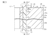
ちなみに、上記では、永久磁石23の突出部23x1,23y1をその永久磁石23の直線部23a及び屈曲部23bを含むV字経路で連続し厚さWmで一定としたものであるが、図6、図7及び図8に示すように、永久磁石23の屈曲部23bの厚さWm1を直線部23aの厚さWmより幅狭に構成したものも検討してみた。
Incidentally, in the above, the protruding portions 23x1, 23y1 of the permanent magnet 23 are continuous in a V-shaped path including the straight portion 23a and the bent portion 23b of the permanent magnet 23, and are constant in thickness Wm. As shown in FIGS. 7 and 8, a case in which the thickness Wm1 of the bent portion 23b of the permanent magnet 23 is narrower than the thickness Wm of the straight portion 23a is also examined.
図9(a)は、屈曲部23bを厚さWm1と若干幅狭とした形態と比較例との比較結果である。
FIG. 9A is a comparison result between a form in which the bent portion 23b has a thickness of Wm1 and a slightly narrow width and a comparative example.
誘起電圧Vm及び誘起電圧/磁石体積(Vm/Va)のいずれに関しても、本形態の方が比較例よりも大きくなる。突出部23x1,23y1の厚さが大きいほど、永久磁石23の埋込磁石部23mの磁束がロータコア22の軸方向端面22c,22dから漏れ出る経路長を長くでき磁束の漏れを抑制できるが、永久磁石23の屈曲部23bは直線部23aより磁束の漏れが少ない部位であるため、屈曲部23bの厚さWm1を若干幅狭に調整することは可能である。つまり換言すると、Vm値及びVm/Va値がともに比較例よりも本形態が大きくなるように永久磁石23の屈曲部23bの厚さWm1を適切に変更した態様である。なお、図9(b)に示す突出部23x1,23y1の突出量D1と誘起電圧Vmとの関係としては、突出部23x1,23y1の突出量D1がゼロ以上となると、有効磁束φaの増加に伴いVm値が増加するが、この態様では早めに頭打ちとなる変化となる。一方、図9(c)に示す突出量D1と誘起電圧/磁石体積(Vm/Va)との関係としては、屈曲部23bを幅狭の厚さWm1としたことによる磁石体積Vaの減少にて、突出部23x1,23y1の突出量D1がゼロ以上となってもVm/Va値が暫く上昇し、次第に低下していく。これは、永久磁石23の埋込磁石部23mの磁束をロータコア22の軸方向端面22c,22dから極力漏れ出ないようにしつつ、永久磁石23を極力軽量化した結果である。
Regarding both the induced voltage Vm and the induced voltage / magnet volume (Vm / Va), this embodiment is larger than the comparative example. The larger the thickness of the protruding portions 23x1, 23y1, the longer the path length of the magnetic flux of the embedded magnet portion 23m of the permanent magnet 23 leaking from the axial end faces 22c and 22d of the rotor core 22, and the leakage of the magnetic flux can be suppressed, but it is permanent. Since the bent portion 23b of the magnet 23 is a portion where the magnetic flux leaks less than that of the straight portion 23a, it is possible to adjust the thickness Wm1 of the bent portion 23b to be slightly narrower. That is, in other words, the thickness Wm1 of the bent portion 23b of the permanent magnet 23 is appropriately changed so that both the Vm value and the Vm / Va value are larger than those in the comparative example. As for the relationship between the protrusion amount D1 of the protrusion 23x1,23y1 and the induced voltage Vm shown in FIG. 9B, when the protrusion amount D1 of the protrusion 23x1,23y1 becomes zero or more, the effective magnetic flux φa increases. The Vm value increases, but in this embodiment, the change reaches a plateau early. On the other hand, the relationship between the protrusion amount D1 and the induced voltage / magnet volume (Vm / Va) shown in FIG. 9 (c) is that the magnet volume Va is reduced by setting the bent portion 23b to a narrow thickness Wm1. Even if the protrusion amount D1 of the protrusions 23x1, 23y1 becomes zero or more, the Vm / Va value rises for a while and gradually decreases. This is a result of reducing the weight of the permanent magnet 23 as much as possible while preventing the magnetic flux of the embedded magnet portion 23m of the permanent magnet 23 from leaking from the axial end faces 22c and 22d of the rotor core 22 as much as possible.
本実施形態の効果について説明する。
The effect of this embodiment will be explained.
(1)ロータコア22の平坦面をなす軸方向端面22c,22dから永久磁石23の端部が突出部23x1,23y1として突出しているため、ロータコア22内に位置する永久磁石23の埋込磁石部23mの磁束がロータコア22の軸方向端面22c,22dから漏れ出ようとするにはその突出部23x1,23y1を越える態様となる。つまり、埋込磁石部23mの磁束の漏れ出ようとする経路長が長くなるため、埋込磁石部23mの磁束の漏れを抑制することができる。永久磁石23の埋込磁石部23mの磁束は回転電機Mのトルクに寄与する有効磁束φaとなるため、これを極力漏れ出ないようにして有効磁束φaの磁束量を増加させることで、回転電機Mのトルク性能の向上を十分に期待することができる。しかも、ロータコア22の軸方向端面22c,22dは一般的な平坦面形状であり、永久磁石23の端部をそのロータコア22の軸方向端面22c,22dから突出させるだけの簡易な対応にて実現することができる。
(1) Since the end portion of the permanent magnet 23 protrudes as a protruding portion 23x1,23y1 from the axial end surfaces 22c and 22d forming the flat surface of the rotor core 22, the embedded magnet portion 23m of the permanent magnet 23 located in the rotor core 22 In order for the magnetic flux of the rotor core 22 to leak from the axial end faces 22c and 22d of the rotor core 22, the protrusion exceeds the protrusions 23x1,23y1. That is, since the path length at which the magnetic flux of the embedded magnet portion 23m tends to leak becomes long, it is possible to suppress the leakage of the magnetic flux of the embedded magnet portion 23m. Since the magnetic flux of the embedded magnet portion 23m of the permanent magnet 23 becomes an effective magnetic flux φa that contributes to the torque of the rotary electric machine M, the magnetic flux amount of the effective magnetic flux φa is increased by preventing this from leaking as much as possible. It can be fully expected that the torque performance of M will be improved. Moreover, the axial end faces 22c and 22d of the rotor core 22 have a general flat surface shape, and the end portion of the permanent magnet 23 can be realized by simply projecting from the axial end faces 22c and 22d of the rotor core 22. be able to.
(2)永久磁石23の突出部23x1,23y1は、ロータコア22の両側の軸方向端面22c,22dから同様な突出形状をなしているため、ロータ20の重量バランスを良好に維持等の効果を得ることができる。
(2) Since the protruding portions 23x1, 23y1 of the permanent magnet 23 have the same protruding shape from the axial end faces 22c and 22d on both sides of the rotor core 22, the effect of maintaining a good weight balance of the rotor 20 can be obtained. be able to.
(3)永久磁石23の突出部23x1,23y1は、ロータコア22の軸方向端面22c,22dに沿った永久磁石23のV字形状の延びる方向に連続して設けられるため、トルクに寄与する埋込磁石部23mの磁束の漏れを永久磁石23の全体にわたってより確実に抑制することができる。
(3) Since the protruding portions 23x1, 23y1 of the permanent magnet 23 are continuously provided in the extending direction of the V-shape of the permanent magnet 23 along the axial end faces 22c and 22d of the rotor core 22, they are embedded to contribute to the torque. Leakage of the magnetic flux of the magnet portion 23m can be more reliably suppressed over the entire permanent magnet 23.
(4)永久磁石23の突出部23x1,23y1は、ロータコア22の軸方向端面22c,22dからの突出量D1が一定となるように設けられるため、トルクに寄与する埋込磁石部23mの磁束の漏れを各箇所で同様に抑制することができる。
(4) The protruding portions 23x1, 23y1 of the permanent magnet 23 are provided so that the amount of protrusion D1 from the axial end faces 22c and 22d of the rotor core 22 is constant, so that the magnetic flux of the embedded magnet portion 23m that contributes to torque is increased. Leakage can be similarly suppressed at each location.
(5)永久磁石23の突出部23x1,23y1は、ロータコア22の埋込磁石部23mから連続して一体的に設けられるため、同材料で同時に形成できる等、容易に形成することができる。
(5) Since the protruding portions 23x1, 23y1 of the permanent magnet 23 are continuously and integrally provided from the embedded magnet portion 23m of the rotor core 22, they can be easily formed by using the same material at the same time.
(6)永久磁石23の突出部23x1,23y1は、ロータ20の周方向配置される全部の永久磁石23に対して設けられるため、トルクに寄与する埋込磁石部23mの磁束の漏れを全部の永久磁石23において抑制することができる。また、ロータ20の重量バランスを良好に維持等の効果を得ることができる。
(6) Since the protruding portions 23x1, 23y1 of the permanent magnet 23 are provided for all the permanent magnets 23 arranged in the circumferential direction of the rotor 20, all the leakage of the magnetic flux of the embedded magnet portion 23m that contributes to the torque is caused. It can be suppressed by the permanent magnet 23. Further, it is possible to obtain an effect such as maintaining a good weight balance of the rotor 20.
本実施形態は、以下のように変更して実施することができる。本実施形態及び以下の変更例は、技術的に矛盾しない範囲で互いに組み合わせて実施することができる。
This embodiment can be changed and implemented as follows. The present embodiment and the following modified examples can be implemented in combination with each other within a technically consistent range.
・ロータコア22の軸方向端面22c,22dから突出する永久磁石23の端部の突出部23x1,23y1の構成を適宜変更してもよい。
The configuration of the protruding portions 23x1, 23y1 at the ends of the permanent magnets 23 protruding from the axial end faces 22c and 22d of the rotor core 22 may be appropriately changed.
例えば、永久磁石23の直線部23a及び屈曲部23bを含むV字経路で突出部を部分的に設けてもよい。
For example, a protruding portion may be partially provided in a V-shaped path including a straight portion 23a and a bent portion 23b of the permanent magnet 23.
図10に示すように、永久磁石23の屈曲部23bのみで突出する突出部23x2,23y2を設けてもよい。突出部23x2,23y2は、ロータコア22の軸方向端面22c,22dの両方に同様に設けられる。
As shown in FIG. 10, a protruding portion 23x2, 23y2 that protrudes only from the bent portion 23b of the permanent magnet 23 may be provided. The protrusions 23x2 and 23y2 are similarly provided on both the axial end faces 22c and 22d of the rotor core 22.
図11に示すように、永久磁石23の直線部23aのみで突出する突出部23x3,23y3を設けてもよい。突出部23x3,23y3は、ロータコア22の軸方向端面22c,22dの両方に同様に設けられる。
As shown in FIG. 11, a protruding portion 23x3, 23y3 that protrudes only from the straight portion 23a of the permanent magnet 23 may be provided. The protrusions 23x3 and 23y3 are similarly provided on both the axial end faces 22c and 22d of the rotor core 22.
図12に示すように、永久磁石23の屈曲部23bで突出する突出部23x2,23y2と、直線部23aの延びる方向において部分的に突出する突出部23x4,23y4とを設けてもよい。突出部23x2,23y2及び突出部23x4,23y4は、ロータコア22の軸方向端面22c,22dの両方に同様に設けられる。
As shown in FIG. 12, a protruding portion 23x2, 23y2 protruding from the bent portion 23b of the permanent magnet 23 and a protruding portion 23x4, 23y4 partially protruding in the extending direction of the straight line portion 23a may be provided. The protrusions 23x2, 23y2 and the protrusions 23x4, 23y4 are similarly provided on both the axial end faces 22c and 22d of the rotor core 22.
特に図示はしないが、永久磁石23のV字形状の一方側の直線部23aと屈曲部23bの半分というように、永久磁石23の突出部をV字形状の片側だけ設けてもよい。
Although not particularly shown, the protruding portion of the permanent magnet 23 may be provided on only one side of the V-shape, such as a straight portion 23a on one side of the V-shape of the permanent magnet 23 and half of the bent portion 23b.
このようにすれば、永久磁石23の磁石材料を低減でき、ロータ20の軽量化が図れる等の効果が期待できる。
By doing so, the magnet material of the permanent magnet 23 can be reduced, and the effect of reducing the weight of the rotor 20 can be expected.
また例えば、ロータコア22の軸方向端面22c,22dのそれぞれで異なる構成の突出部を設けてもよい。そのうち、ロータコア22の軸方向端面22c,22dの一方側にのみ突出部を設ける態様を先に列挙する。
Further, for example, each of the axial end faces 22c and 22d of the rotor core 22 may be provided with protrusions having different configurations. Among them, the mode in which the protruding portion is provided only on one side of the axial end faces 22c and 22d of the rotor core 22 is listed first.
図13に示すように、ロータコア22の軸方向端面22c側にのみ、突出部23x1を設けてもよい。なお、突出部23x1は、上記したように、永久磁石23のV字経路に沿って連続するものである。
As shown in FIG. 13, the protrusion 23x1 may be provided only on the axial end surface 22c side of the rotor core 22. As described above, the protruding portion 23x1 is continuous along the V-shaped path of the permanent magnet 23.
図14に示すように、ロータコア22の軸方向端面22c側にのみ、永久磁石23の屈曲部23bのみで突出する突出部23x2を設けてもよい。
As shown in FIG. 14, a protruding portion 23x2 that protrudes only from the bent portion 23b of the permanent magnet 23 may be provided only on the axial end surface 22c side of the rotor core 22.
図15に示すように、ロータコア22の軸方向端面22c側にのみ、永久磁石23の直線部23aのみで突出する突出部23x3を設けてもよい。
As shown in FIG. 15, a protruding portion 23x3 that protrudes only from the linear portion 23a of the permanent magnet 23 may be provided only on the axial end surface 22c side of the rotor core 22.
図16に示すように、ロータコア22の軸方向端面22c側にのみ、永久磁石23の屈曲部23bで突出する突出部23x2と、直線部23aの延びる方向において部分的に突出する突出部23x4とを設けてもよい。
As shown in FIG. 16, only on the axial end surface 22c side of the rotor core 22, the protruding portion 23x2 protruding from the bent portion 23b of the permanent magnet 23 and the protruding portion 23x4 partially protruding in the extending direction of the straight portion 23a are provided. It may be provided.
このようにしても、永久磁石23の磁石材料を低減でき、ロータ20の軽量化が図れる等の効果が期待できる。
Even in this way, the magnet material of the permanent magnet 23 can be reduced, and the effect of reducing the weight of the rotor 20 can be expected.
また、ロータコア22の軸方向端面22c,22dのそれぞれに突出部が設けられるものにおいて、そのそれぞれで異なる構成の突出部を設ける態様を次に列挙する。
Further, in the case where the protrusions are provided on the axial end faces 22c and 22d of the rotor core 22, the embodiments in which the protrusions having different configurations are provided are listed below.
図17に示すように、ロータコア22の軸方向端面22c側では、永久磁石23の屈曲部23bのみで突出する突出部23x2を設け、ロータコア22の軸方向端面22d側では、永久磁石23の屈曲部23bで突出する突出部23y2と、直線部23aの延びる方向において部分的に突出する突出部23y4とを設けてもよい。
As shown in FIG. 17, on the axial end surface 22c side of the rotor core 22, a protruding portion 23x2 is provided that protrudes only by the bent portion 23b of the permanent magnet 23, and on the axial end surface 22d side of the rotor core 22, the bent portion of the permanent magnet 23 is provided. A protruding portion 23y2 protruding from the 23b and a protruding portion 23y4 partially protruding in the extending direction of the straight portion 23a may be provided.
図18に示すように、ロータコア22の軸方向端面22c側では、永久磁石23のV字経路に沿って連続する突出部23x1を設け、ロータコア22の軸方向端面22d側では、永久磁石23の直線部23aのみで突出する突出部23y3を設けてもよい。
As shown in FIG. 18, on the axial end surface 22c side of the rotor core 22, a continuous protrusion 23x1 is provided along the V-shaped path of the permanent magnet 23, and on the axial end surface 22d side of the rotor core 22, a straight line of the permanent magnet 23 is provided. A protruding portion 23y3 that protrudes only from the portion 23a may be provided.
図19に示すように、ロータコア22の軸方向端面22c側では、永久磁石23の屈曲部23bで突出する突出部23x2と、直線部23aの延びる方向において部分的に突出する突出部23x4とを設け、ロータコア22の軸方向端面22d側では、永久磁石23のV字経路に沿って連続する突出部23y1を設けてもよい。
As shown in FIG. 19, on the axial end surface 22c side of the rotor core 22, a protruding portion 23x2 protruding from the bent portion 23b of the permanent magnet 23 and a protruding portion 23x4 partially protruding in the extending direction of the straight portion 23a are provided. On the axial end surface 22d side of the rotor core 22, a continuous protrusion 23y1 may be provided along the V-shaped path of the permanent magnet 23.
このようにすれば、永久磁石23の突出形状を含めたロータ20の外形形状の自由度を高くできる等の効果が期待できる。
By doing so, it is expected that the degree of freedom of the outer shape of the rotor 20 including the protruding shape of the permanent magnet 23 can be increased.
また例えば、永久磁石23のV字経路の延びる方向と直交する厚さ方向で突出部を部分的に設けてもよい。
Further, for example, the protruding portion may be partially provided in the thickness direction orthogonal to the extending direction of the V-shaped path of the permanent magnet 23.
図20に示すように、永久磁石23の厚さ方向中央部に幅狭形状をなす突出部23x5,23y5を設けてもよい。突出部23x5,23y5は、永久磁石23のV字経路に沿って連続するものである。また、突出部23x5,23y5は、ロータコア22の軸方向端面22c,22dの両方に同様に設けられる。
As shown in FIG. 20, a protruding portion 23x5, 23y5 having a narrow shape may be provided at the central portion in the thickness direction of the permanent magnet 23. The protrusions 23x5 and 23y5 are continuous along the V-shaped path of the permanent magnet 23. Further, the protrusions 23x5 and 23y5 are similarly provided on both the axial end faces 22c and 22d of the rotor core 22.
図21に示すように、永久磁石23の厚さ方向中央部に溝部23z1を有する突出部23x6,23y6を設けてもよい。溝部23z1は、突出部23x6,23y6の突出量D1と同じ深さをなしている。突出部23x6,23y6は、永久磁石23のV字経路に沿って連続するものである。また、突出部23x6,23y6は、ロータコア22の軸方向端面22c,22dの両方に同様に設けられる。
As shown in FIG. 21, a protruding portion 23x6, 23y6 having a groove portion 23z1 may be provided at the central portion in the thickness direction of the permanent magnet 23. The groove portion 23z1 has the same depth as the protrusion amount D1 of the protrusions 23x6, 23y6. The protrusions 23x6, 23y6 are continuous along the V-shaped path of the permanent magnet 23. Further, the protrusions 23x6, 23y6 are similarly provided on both the axial end faces 22c and 22d of the rotor core 22.
図22に示すように、永久磁石23の突出部23x6,23y6の厚さ方向中央部に設けた溝部23z2の深さを、突出部23x6,23y6の突出量D1と異ならせてもよい。溝部23z2は、同図22のように突出部23x6,23y6の突出量D1よりも浅くしてもよく、深くしてもよい。
As shown in FIG. 22, the depth of the groove portion 23z2 provided in the central portion of the protruding portion 23x6, 23y6 of the permanent magnet 23 in the thickness direction may be different from the protruding amount D1 of the protruding portion 23x6, 23y6. The groove portion 23z2 may be shallower or deeper than the protrusion amount D1 of the protrusions 23x6, 23y6 as shown in FIG. 22.
このようにしても、永久磁石23の磁石材料を低減でき、ロータ20の軽量化が図れる等の効果が期待できる。
Even in this way, the magnet material of the permanent magnet 23 can be reduced, and the effect of reducing the weight of the rotor 20 can be expected.
また例えば、永久磁石23に設ける突出部の形状を変更してもよい。突出部の部位によって突出量D1を変化させてもよい。
Further, for example, the shape of the protruding portion provided on the permanent magnet 23 may be changed. The protrusion amount D1 may be changed depending on the portion of the protrusion.
図23に示すように、永久磁石23の屈曲部23bに設けた突出部23x7,23y7を斜面形状としてもよい。突出部23x7,23y7は、永久磁石23のV字形状の内側が高く、外側が低い斜面形状にて構成されている。突出部23x7,23y7は、ロータコア22の軸方向端面22c,22dの両方に同様に設けられる。
As shown in FIG. 23, the protruding portions 23x7, 23y7 provided in the bent portion 23b of the permanent magnet 23 may have a slope shape. The protrusions 23x7 and 23y7 are formed in a slope shape in which the inside of the V-shape of the permanent magnet 23 is high and the outside is low. The protrusions 23x7 and 23y7 are similarly provided on both the axial end faces 22c and 22d of the rotor core 22.
図24に示すように、永久磁石23のV字経路の延びる方向に連続する突出部23x8,23y8であり、屈曲部23bの部分が最も高く、そこから直線部23aの径方向外側端部23cに向けて次第に低くなる斜面形状としてもよい。突出部23x8,23y8は、ロータコア22の軸方向端面22c,22dの両方に同様に設けられる。
As shown in FIG. 24, there are protrusions 23x8, 23y8 that are continuous in the extending direction of the V-shaped path of the permanent magnet 23, the bent portion 23b is the highest, and the radial outer end portion 23c of the straight portion 23a is reached. It may be a slope shape that gradually becomes lower toward the bottom. The protrusions 23x8 and 23y8 are similarly provided on both the axial end faces 22c and 22d of the rotor core 22.
このようにしても、永久磁石23の磁石材料を低減でき、ロータ20の軽量化が図れる等の効果が期待できる。また、永久磁石23の突出形状を含めたロータ20の外形形状の自由度を高くできる等の効果が期待できる。
Even in this way, the magnet material of the permanent magnet 23 can be reduced, and the effect of reducing the weight of the rotor 20 can be expected. Further, it is expected that the degree of freedom of the outer shape of the rotor 20 including the protruding shape of the permanent magnet 23 can be increased.
また例えば、永久磁石23の突出部を埋込磁石部23mと別体としてもよい。この場合、互いの磁石材料を異ならせてもよい。
Further, for example, the protruding portion of the permanent magnet 23 may be separated from the embedded magnet portion 23 m. In this case, the magnet materials may be different from each other.
図25に示すように、永久磁石23の突出部23x9,23y9は、V字経路の延びる方向に連続するであり、ロータコア22の軸方向端面22c,22dの両方に同様に設けられる。突出部23x9,23y9は、埋込磁石部23mよりも安価な磁石材料をもちいてもよい。また、突出部23x9,23y9は、埋込磁石部23mとは磁力の異なる磁石材料を用いてもよい。また、突出部23x9,23y9は、埋込磁石部23mと強度の異なる磁石材料を用いてもよく、ロータコア22の軸方向端面22c,22dから露出することを考慮すると高強度に構成してもよい。また、突出部23x9,23y9は、埋込磁石部23mと同時に形成してもよく、後付けしてもよい。
As shown in FIG. 25, the protruding portions 23x9, 23y9 of the permanent magnet 23 are continuous in the extending direction of the V-shaped path, and are similarly provided on both the axial end faces 22c and 22d of the rotor core 22. The protruding portions 23x9 and 23y9 may use a magnet material that is cheaper than the embedded magnet portion 23m. Further, the protruding portions 23x9 and 23y9 may use a magnet material having a magnetic force different from that of the embedded magnet portion 23m. Further, the protruding portions 23x9 and 23y9 may be made of a magnet material having a strength different from that of the embedded magnet portion 23m, and may be configured to have high strength in consideration of being exposed from the axial end faces 22c and 22d of the rotor core 22. .. Further, the protruding portions 23x9 and 23y9 may be formed at the same time as the embedded magnet portion 23m, or may be retrofitted.
このようにすれば、永久磁石23の構成の自由度を高くできる等の効果が期待できる。
By doing so, effects such as increasing the degree of freedom in the configuration of the permanent magnet 23 can be expected.
また例えば、ロータ20の周方向に配置される永久磁石23の全てにロータコア22の軸方向端面22c,22dから突出する突出部を設けなくてもよい。
Further, for example, it is not necessary to provide all the permanent magnets 23 arranged in the circumferential direction of the rotor 20 with protrusions protruding from the axial end faces 22c and 22d of the rotor core 22.
図26に示すように、周方向に複数配置される永久磁石23の1つ置きに選択的に突出部23x1を設けてもよい。なお、1つ置き以外の等間隔置きでもよく、不等間隔置きでもよい。
As shown in FIG. 26, a protrusion 23x1 may be selectively provided in every other permanent magnet 23 arranged in the circumferential direction. In addition, it may be placed at equal intervals other than every other one, or it may be placed at unequal intervals.
このようにしても、永久磁石23の磁石材料を低減でき、ロータ20の軽量化が図れる等の効果が期待できる。
Even in this way, the magnet material of the permanent magnet 23 can be reduced, and the effect of reducing the weight of the rotor 20 can be expected.
・ロータコア22の軸方向端面22c,22dにおいて、図27に示すように、突出部23x1,23y1を含む永久磁石23の成形の際にその磁石材料の余裕分が溜まる凹部24aを磁石収容孔24の開口部周りに設けてもよい。このようにすれば、磁石材料の余裕分が凹部24aに収めることが可能なため、ロータコア22の軸方向端面22c,22dに永久磁石23のバリとして突出することが抑制可能である。
As shown in FIG. 27, in the axial end faces 22c and 22d of the rotor core 22, the recess 24a in which the margin of the magnet material is accumulated when the permanent magnet 23 including the protrusions 23x1, 23y1 is formed is formed in the magnet accommodating hole 24. It may be provided around the opening. By doing so, since the margin of the magnet material can be accommodated in the recess 24a, it is possible to suppress the protrusion of the permanent magnet 23 as a burr on the axial end faces 22c and 22d of the rotor core 22.
・永久磁石23はV字状に限らず、U字状等、ロータ20の径方向内側に凸のその他の折返し形状であってもよい。また、I字状等、折返し形状以外であってもよい。
-The permanent magnet 23 is not limited to a V-shape, but may have another folded shape that is convex inward in the radial direction of the rotor 20, such as a U-shape. Further, it may have a shape other than the folded shape such as an I shape.
・ロータコア22の磁石収容孔24に磁石材料を射出成形して永久磁石23を構成したが、永久磁石23を予め作製しておき、ロータコア22の磁石収容孔24に挿入して固定する態様であってもよい。
A permanent magnet 23 is formed by injection molding a magnet material into the magnet accommodating hole 24 of the rotor core 22. However, the permanent magnet 23 is prepared in advance and inserted into the magnet accommodating hole 24 of the rotor core 22 to be fixed. You may.
・上記以外、ロータ20の構成及び回転電機Mの構成を適宜変更してもよい。
-Other than the above, the configuration of the rotor 20 and the configuration of the rotary electric machine M may be changed as appropriate.
・図28は、比較構成1、比較構成2及び上記実施形態において、回転電機Mにおいて生じる誘起電圧Vmの大きさを比較したグラフである。上記実施形態では、ステータコア11の軸方向長さが、ロータコア22の軸方向長さと等しく設定されている。なお、当該ステータコア11の軸方向長さは、例えば、ティース12の先端面12aの軸方向長さである。また、上記実施形態で言及したように、永久磁石23の軸方向長さがロータコア22の軸方向長さよりも長く形成されることで、突出部23x1,23y1が形成されている。すなわち、上記実施形態において、永久磁石23の軸方向長さは、ロータコア22及びステータコア11の軸方向長さよりも長い。なお、永久磁石23の突出部23x1,23y1は、ステータコア11の軸方向両端面よりも軸方向の側方に位置している。
FIG. 28 is a graph comparing the magnitudes of the induced voltage Vm generated in the rotary electric machine M in the comparative configuration 1, the comparative configuration 2, and the above embodiment. In the above embodiment, the axial length of the stator core 11 is set to be equal to the axial length of the rotor core 22. The axial length of the stator core 11 is, for example, the axial length of the tip surface 12a of the teeth 12. Further, as mentioned in the above embodiment, the protruding portion 23x1,23y1 is formed by forming the permanent magnet 23 in the axial direction longer than the axial length of the rotor core 22. That is, in the above embodiment, the axial length of the permanent magnet 23 is longer than the axial length of the rotor core 22 and the stator core 11. The protruding portions 23x1, 23y1 of the permanent magnet 23 are located laterally in the axial direction with respect to both end faces in the axial direction of the stator core 11.
上記実施形態に対し、比較構成1は、永久磁石23、ロータコア22及びステータコア11の各々の軸方向長さが互いに等しい構成である。
In contrast to the above embodiment, the comparative configuration 1 has a configuration in which the axial lengths of the permanent magnet 23, the rotor core 22, and the stator core 11 are equal to each other.
比較構成2では、永久磁石23の軸方向長さが、ロータコア22の軸方向長さと等しく設定される。すなわち、比較構成2では、永久磁石23が磁石収容孔24から軸方向に突出する部位が形成されない。また、比較構成2では、ロータコア22及び永久磁石23の軸方向長さは、ステータコア11の軸方向長さよりも長く設定される。
In the comparative configuration 2, the axial length of the permanent magnet 23 is set equal to the axial length of the rotor core 22. That is, in the comparative configuration 2, a portion where the permanent magnet 23 protrudes in the axial direction from the magnet accommodating hole 24 is not formed. Further, in the comparative configuration 2, the axial lengths of the rotor core 22 and the permanent magnet 23 are set longer than the axial length of the stator core 11.
図28に示すように、比較構成1に対し、比較構成2及び上記実施形態では、誘起電圧Vmが大きくなる。これは、ステータコア11の軸方向の全体が永久磁石23の軸方向の範囲に含まれるためと考えられる。
As shown in FIG. 28, the induced voltage Vm is larger in the comparative configuration 2 and the above embodiment than in the comparative configuration 1. It is considered that this is because the entire axial direction of the stator core 11 is included in the axial range of the permanent magnet 23.
また、比較構成2と上記実施形態では、誘起電圧Vmの大きさがほぼ等しくなる。上記実施形態では、ロータコア22の軸方向長さをステータコア11の軸方向長さと等しくし、永久磁石23のみ軸方向長さを長くしている。このため、比較構成2に対して上記実施形態では、ロータコア22の軸方向長さを短く構成できる。したがって、上記実施形態のように、永久磁石23の軸方向長さをロータコア22及びステータコア11の軸方向長さよりも長く構成することで、誘起電圧Vm向上させつつ、ロータコア22ひいては回転電機Mの軽量化に寄与できる。
Further, in the comparative configuration 2 and the above embodiment, the magnitudes of the induced voltage Vm are almost the same. In the above embodiment, the axial length of the rotor core 22 is equal to the axial length of the stator core 11, and the axial length of only the permanent magnet 23 is increased. Therefore, in the above embodiment, the axial length of the rotor core 22 can be shortened with respect to the comparative configuration 2. Therefore, as in the above embodiment, by forming the axial length of the permanent magnet 23 longer than the axial length of the rotor core 22 and the stator core 11, the induced voltage Vm is improved, and the weight of the rotor core 22 and thus the rotary electric machine M is reduced. Can contribute to the conversion.
・上記実施形態では、ロータコア22が単一の部品で構成されるが、これ以外に例えば、軸方向に並設した複数のロータコア部にてロータコア22を構成してもよい。例えば、図29に示す構成では、軸方向に並設された2つのロータコア部にてロータコア22が構成されている。以下の説明では、当該2つのロータコア部のうちの一方を第1ロータコア部31と称し、他方を第2ロータコア部32と称する。また、図29に示す構成において、上記実施形態と同様の構成については、上記実施形態と同様の符号を付してその詳細な説明を省略する場合がある。
-In the above embodiment, the rotor core 22 is composed of a single component, but in addition to this, for example, the rotor core 22 may be configured by a plurality of rotor core portions arranged side by side in the axial direction. For example, in the configuration shown in FIG. 29, the rotor core 22 is configured by two rotor core portions arranged side by side in the axial direction. In the following description, one of the two rotor core portions will be referred to as a first rotor core portion 31, and the other will be referred to as a second rotor core portion 32. Further, in the configuration shown in FIG. 29, the same configurations as those in the above embodiment may be designated by the same reference numerals as those in the above embodiment, and detailed description thereof may be omitted.
図29に示すように、ロータ20は、回転軸21と、第1ロータコア部31を有する第1ロータ部R1と、第2ロータコア部32を有する第2ロータ部R2と、を備えている。
As shown in FIG. 29, the rotor 20 includes a rotating shaft 21, a first rotor portion R1 having a first rotor core portion 31, and a second rotor portion R2 having a second rotor core portion 32.
第1ロータ部R1と第2ロータ部R2とは、ロータ20の軸線L1に沿った方向に並設されている。第1ロータ部R1及び第2ロータ部R2は、回転軸21と一体回転可能に構成されている。第1ロータ部R1及び第2ロータ部R2は、回転軸21がハウジング14に設けられる図示略の軸受に支持されることで、ステータ10に対して回転可能に配置されている。
The first rotor portion R1 and the second rotor portion R2 are arranged side by side in the direction along the axis L1 of the rotor 20. The first rotor portion R1 and the second rotor portion R2 are configured to be integrally rotatable with the rotating shaft 21. The first rotor portion R1 and the second rotor portion R2 are rotatably arranged with respect to the stator 10 by supporting the rotating shaft 21 with a bearing (not shown) provided in the housing 14.
第1ロータコア部31は、回転軸21が中心部に嵌挿される略円柱状をなしている。第2ロータコア部32も同様に、回転軸21が中心部に嵌挿される略円柱状をなしている。第1ロータ部R1は、第1ロータコア部31に埋設された永久磁石23を備えている。また、第2ロータ部R2は、第2ロータコア部32に埋設された永久磁石23を備えている。
The first rotor core portion 31 has a substantially cylindrical shape in which the rotating shaft 21 is inserted into the central portion. Similarly, the second rotor core portion 32 also has a substantially cylindrical shape in which the rotating shaft 21 is fitted into the central portion. The first rotor portion R1 includes a permanent magnet 23 embedded in the first rotor core portion 31. Further, the second rotor portion R2 includes a permanent magnet 23 embedded in the second rotor core portion 32.
第1ロータコア部31と第2ロータコア部32とは、例えば、同一構造の部品である。第1ロータコア部31及び第2ロータコア部32の各々は、磁性金属材料にて構成されている。なお、第1ロータコア部31及び第2ロータコア部32の各々は、例えば複数枚の電磁鋼板を軸線L1方向に積層して構成されている。第1ロータコア部31と第2ロータコア部32とは、軸方向に並設されてロータコア22を構成する。
The first rotor core portion 31 and the second rotor core portion 32 are, for example, parts having the same structure. Each of the first rotor core portion 31 and the second rotor core portion 32 is made of a magnetic metal material. Each of the first rotor core portion 31 and the second rotor core portion 32 is configured by, for example, laminating a plurality of electromagnetic steel sheets in the axis L1 direction. The first rotor core portion 31 and the second rotor core portion 32 are arranged side by side in the axial direction to form the rotor core 22.
第1ロータコア部31と第2ロータコア部32の各々において、軸線L1と直交する断面形状は、例えば、上記実施形態のロータコア22における軸線L1と直交する断面形状と同様である。すなわち、第1ロータコア部31と第2ロータコア部32はそれぞれ、永久磁石23を収容するための磁石収容孔24を有している。第1ロータコア部31と第2ロータコア部32の各々において、磁石収容孔24の周方向における数や形状等の構成は、例えば、上記実施形態の磁石収容孔24と同様である。
In each of the first rotor core portion 31 and the second rotor core portion 32, the cross-sectional shape orthogonal to the axis L1 is, for example, the same as the cross-sectional shape orthogonal to the axis L1 in the rotor core 22 of the above embodiment. That is, the first rotor core portion 31 and the second rotor core portion 32 each have a magnet accommodating hole 24 for accommodating the permanent magnet 23. In each of the first rotor core portion 31 and the second rotor core portion 32, the configuration such as the number and shape of the magnet accommodating holes 24 in the circumferential direction is the same as, for example, the magnet accommodating holes 24 of the above embodiment.
第1ロータコア部31及び第2ロータコア部32の各々において、永久磁石23のV字の折返し形状の内側であり永久磁石23よりも径方向外側に位置する部位は、ステータ10と対向してリラクタンストルクを得るための外側コア部25として機能する。そして、第1ロータ部R1及び第2ロータ部R2の各々は、永久磁石23と外側コア部25とを含むロータ磁極部26を8つ有している。ロータ磁極部26は、周方向において交互にN極、S極として機能する。
In each of the first rotor core portion 31 and the second rotor core portion 32, the portion located inside the V-shaped folded shape of the permanent magnet 23 and radially outside the permanent magnet 23 is opposed to the stator 10 and has a reluctance torque. Functions as the outer core portion 25 for obtaining. Each of the first rotor portion R1 and the second rotor portion R2 has eight rotor magnetic pole portions 26 including a permanent magnet 23 and an outer core portion 25. The rotor magnetic poles 26 alternately function as N poles and S poles in the circumferential direction.
第1ロータ部R1及び第2ロータ部R2の各々において、各ロータ磁極部26は、周方向における磁極中心Cを有している。各磁極中心Cは、周方向において互いに等間隔に設定されている。本例では、8個のロータ磁極部26の各々の各磁極中心Cは、互いに周方向に45°間隔に設定されている。なお、各ロータ磁極部26において、磁極中心Cは、永久磁石23の周方向中心線Lsと一致している。
In each of the first rotor portion R1 and the second rotor portion R2, each rotor magnetic pole portion 26 has a magnetic pole center C in the circumferential direction. The magnetic pole centers C are set at equal intervals from each other in the circumferential direction. In this example, the magnetic pole centers C of each of the eight rotor magnetic pole portions 26 are set at intervals of 45 ° in the circumferential direction. In each rotor magnetic pole portion 26, the magnetic pole center C coincides with the circumferential center line Ls of the permanent magnet 23.
第2ロータ部R2のロータ磁極部26は、第1ロータ部R1のロータ磁極部26に対して周方向にずれている。本例では、第1ロータ部R1と第2ロータ部R2とは互いに同一構成であり、第1ロータ部R1に対して第2ロータ部R2を所定角度だけ回転させたロータ20の構成となっている。これにより、第2ロータ部R2の磁極中心Cが、第1ロータ部R1の磁極中心Cに対して周方向に所定角度ずれている。以下では、第1ロータ部R1の磁極中心Cに対する第2ロータ部R2の磁極中心Cの周方向へのずれ角度を、スキュー角θと称する。
The rotor magnetic pole portion 26 of the second rotor portion R2 is displaced in the circumferential direction with respect to the rotor magnetic pole portion 26 of the first rotor portion R1. In this example, the first rotor portion R1 and the second rotor portion R2 have the same configuration as each other, and the second rotor portion R2 is rotated by a predetermined angle with respect to the first rotor portion R1 to form a rotor 20. There is. As a result, the magnetic pole center C of the second rotor portion R2 is displaced by a predetermined angle in the circumferential direction with respect to the magnetic pole center C of the first rotor portion R1. Hereinafter, the deviation angle of the second rotor portion R2 with respect to the magnetic pole center C of the first rotor portion R1 in the circumferential direction is referred to as a skew angle θ.
本例のスキュー角θは、ロータ20の極数をpとし、当該極数pとステータ10のスロット数の最小公倍数をLとして、次式(a)に基づいて設定される。
The skew angle θ in this example is set based on the following equation (a), where p is the number of poles of the rotor 20, and L is the least common multiple of the number of poles p and the number of slots of the stator 10.
θ=180/L…(a)
ロータ20の極数pは、第1ロータ部R1及び第2ロータ部R2の各々におけるロータ磁極部26の数であり、本例では8極である。また、本例では、スロット数は12個である。すなわち、本例のスキュー角θは、式(a)にp=8、L=24を代入して得られる7.5[°]に設定されている。 θ = 180 / L ... (a)
The number of poles p of therotor 20 is the number of rotor magnetic pole portions 26 in each of the first rotor portion R1 and the second rotor portion R2, and is 8 poles in this example. Further, in this example, the number of slots is 12. That is, the skew angle θ of this example is set to 7.5 [°] obtained by substituting p = 8 and L = 24 into the equation (a).
ロータ20の極数pは、第1ロータ部R1及び第2ロータ部R2の各々におけるロータ磁極部26の数であり、本例では8極である。また、本例では、スロット数は12個である。すなわち、本例のスキュー角θは、式(a)にp=8、L=24を代入して得られる7.5[°]に設定されている。 θ = 180 / L ... (a)
The number of poles p of the
図30は、スキュー角θを7.5[°]に設定した構成における、ロータ20の回転角とコギングトルクの大きさとの関係を示している。同図では、第1ロータ部R1で生じるコギングトルクをT1とし、第2ロータ部R2で生じるコギングトルクをT2とし、コギングトルクT1,T2を合成したロータ20全体で生じる合成コギングトルクをT3としてそれぞれ表している。スキュー角θが7.5[°]の場合、コギングトルクT1とコギングトルクT2とは互いに逆位相となる。つまり、この場合コギングトルクT1,T2が相殺され、これにより、合成コギングトルクT3が低減される。このように、第1ロータ部R1と第2ロータ部R2の互いの磁極中心Cを周方向にずらすことによって、ロータ20全体の合成コギングトルクT3の低減が可能となる。本例におけるスキュー角θの値は一例であり、回転電機Mの構成に応じてスキュー角θの値は適宜変更可能である。
FIG. 30 shows the relationship between the rotation angle of the rotor 20 and the magnitude of the cogging torque in the configuration in which the skew angle θ is set to 7.5 [°]. In the figure, the cogging torque generated in the first rotor portion R1 is T1, the cogging torque generated in the second rotor portion R2 is T2, and the combined cogging torque generated in the entire rotor 20 in which the cogging torques T1 and T2 are combined is T3. Represents. When the skew angle θ is 7.5 [°], the cogging torque T1 and the cogging torque T2 are in opposite phases to each other. That is, in this case, the cogging torques T1 and T2 are canceled out, whereby the combined cogging torque T3 is reduced. In this way, by shifting the magnetic pole centers C of the first rotor portion R1 and the second rotor portion R2 in the circumferential direction, the combined cogging torque T3 of the entire rotor 20 can be reduced. The value of the skew angle θ in this example is an example, and the value of the skew angle θ can be appropriately changed according to the configuration of the rotary electric machine M.
本例のロータ20においても、上記実施形態と同様に、ロータコア22から軸方向に突出する永久磁石23の部位である突出部23x1,23y1を有している。突出部23x1は、ロータコア22の一方の軸方向端面22cから突出している。本例において、ロータコア22の軸方向端面22cは、第1ロータコア部31における第2ロータ部R2とは反対側の端面である。そして、突出部23x1は、第1ロータ部R1の永久磁石23の一部位である。また、突出部23y1は、ロータコア22の他方の軸方向端面22dから突出している。本例において、ロータコア22の軸方向端面22dは、第2ロータコア部32における第1ロータ部R1とは反対側の端面である。そして、突出部23y1は、第2ロータ部R2の永久磁石23の一部位である。
Similarly to the above embodiment, the rotor 20 of this example also has a protruding portion 23x1,23y1 which is a portion of a permanent magnet 23 protruding in the axial direction from the rotor core 22. The protruding portion 23x1 protrudes from one axial end surface 22c of the rotor core 22. In this example, the axial end surface 22c of the rotor core 22 is the end surface of the first rotor core portion 31 opposite to the second rotor portion R2. The protruding portion 23x1 is a part of the permanent magnet 23 of the first rotor portion R1. Further, the protruding portion 23y1 protrudes from the other axial end surface 22d of the rotor core 22. In this example, the axial end surface 22d of the rotor core 22 is the end surface of the second rotor core portion 32 opposite to the first rotor portion R1. The protruding portion 23y1 is a part of the permanent magnet 23 of the second rotor portion R2.
第1ロータコア部31において、突出部23x1が設けられる軸方向端面22cとは反対側の軸方向端面からは、例えば永久磁石23は突出していない。また、第2ロータコア部32において、突出部23y1が設けられる軸方向端面22dとは反対側の軸方向端面からは、例えば永久磁石23は突出していない。そして、第1ロータコア部31と第2ロータコア部32とは、永久磁石23が突出していない各々の軸方向端面同士が軸方向に対向する態様で並設されている。本例では、例えば、当該軸方向端面同士が接するように、第1ロータコア部31と第2ロータコア部32とが並設されている。
In the first rotor core portion 31, for example, the permanent magnet 23 does not project from the axial end face on the opposite side of the axial end face 22c where the protruding portion 23x1 is provided. Further, in the second rotor core portion 32, for example, the permanent magnet 23 does not protrude from the axial end face on the side opposite to the axial end face 22d where the protruding portion 23y1 is provided. The first rotor core portion 31 and the second rotor core portion 32 are arranged side by side in such a manner that the end faces in the axial direction in which the permanent magnets 23 do not project are opposed to each other in the axial direction. In this example, for example, the first rotor core portion 31 and the second rotor core portion 32 are arranged side by side so that the axial end faces are in contact with each other.
本例においても、突出部23x1,23y1による上記実施形態と同様の効果を得ることが可能である。
Also in this example, it is possible to obtain the same effect as that of the above embodiment by the protruding portions 23x1, 23y1.
なお、本例では、第1ロータコア部31と第2ロータコア部32において、永久磁石23が突出していない各々の軸方向端面同士が接する構成としたが、これに限らず、当該軸方向端面の間に隙間を設けてもよい。また、第1ロータコア部31と第2ロータコア部32における互いに対向する軸方向端面から永久磁石23が突出する構成であってもよい。
In this example, in the first rotor core portion 31 and the second rotor core portion 32, the axial end faces of the permanent magnets 23 are not projected, and the axial end faces are in contact with each other. A gap may be provided in the. Further, the permanent magnet 23 may be configured so as to project from the axial end faces of the first rotor core portion 31 and the second rotor core portion 32 facing each other.
M 回転電機、10 ステータ、20 ロータ、22 ロータコア、22c,22d 軸方向端面、23 永久磁石、23m 埋込磁石部、23x1~23x9,23y1~23y9 突出部、24 磁石収容孔、D1 突出量、R1 第1ロータ部(ロータ部)、R2 第2ロータ部(ロータ部)、31 第1ロータコア部(ロータコア部)、32 第2ロータコア部(ロータコア部)、C 磁極中心。
M rotary electric machine, 10 stator, 20 rotor, 22 rotor core, 22c, 22d axial end face, 23 permanent magnet, 23m embedded magnet part, 23x1-23x9, 23y1-23y9 protrusion, 24 magnet accommodation hole, D1 protrusion amount, R1 1st rotor part (rotor part), R2 2nd rotor part (rotor part), 31 1st rotor core part (rotor core part), 32 2nd rotor core part (rotor core part), C magnetic pole center.
Claims (17)
- ロータコア(22)の磁石収容孔(24)に埋込態様をなす永久磁石(23)を有するロータ(20)であって、
前記ロータコアの軸方向端面(22c,22d)は、平坦面をなしており、
前記永久磁石は、前記ロータコアの軸方向端面から少なくとも一部が突出する突出部(23x1~23x9,23y1~23y9)を有して構成された、ロータ。 A rotor (20) having a permanent magnet (23) embedded in a magnet accommodating hole (24) of the rotor core (22).
The axial end faces (22c, 22d) of the rotor core are flat surfaces.
The permanent magnet is a rotor having a protrusion (23x1 to 23x9, 23y1 to 23y9) having at least a part protruding from the axial end surface of the rotor core. - 前記永久磁石は、ロータの径方向内側に凸の折返し形状をなすものである、請求項1に記載のロータ。 The rotor according to claim 1, wherein the permanent magnet has a folded shape that is convex inward in the radial direction of the rotor.
- 前記永久磁石の突出部は、前記ロータコアの両側の軸方向端面から同様な突出形状をなして構成された、請求項1又は請求項2に記載のロータ。 The rotor according to claim 1 or 2, wherein the protruding portion of the permanent magnet has a similar protruding shape from the axial end faces on both sides of the rotor core.
- 前記永久磁石の突出部は、前記ロータコアの両方の軸方向端面から異なる突出形状にて構成された、請求項1又は請求項2に記載のロータ。 The rotor according to claim 1 or 2, wherein the protruding portion of the permanent magnet is configured to have a different protruding shape from both axial end faces of the rotor core.
- 前記永久磁石の突出部は、前記ロータコアの軸方向端面に沿った前記永久磁石の延びる方向に連続して設けられた、請求項1から請求項4のいずれか1項に記載のロータ。 The rotor according to any one of claims 1 to 4, wherein the protruding portion of the permanent magnet is continuously provided in the extending direction of the permanent magnet along the axial end surface of the rotor core.
- 前記永久磁石の突出部は、前記ロータコアの軸方向端面に沿った前記永久磁石の延びる方向に部分的に設けられた、請求項1から請求項4のいずれか1項に記載のロータ。 The rotor according to any one of claims 1 to 4, wherein the protruding portion of the permanent magnet is partially provided in the extending direction of the permanent magnet along the axial end surface of the rotor core.
- 前記永久磁石の突出部は、前記ロータコアの軸方向端面に沿った前記永久磁石の延びる方向に直交する厚さ方向に部分的に設けられた、請求項1から請求項6のいずれか1項に記載のロータ。 The one according to any one of claims 1 to 6, wherein the protruding portion of the permanent magnet is partially provided in a thickness direction orthogonal to the extending direction of the permanent magnet along the axial end surface of the rotor core. The described rotor.
- 前記永久磁石の突出部は、前記ロータコアの軸方向端面からの突出量(D1)が一定となるように設けられた、請求項1から請求項7のいずれか1項に記載のロータ。 The rotor according to any one of claims 1 to 7, wherein the protruding portion of the permanent magnet is provided so that the amount of protrusion (D1) from the axial end surface of the rotor core is constant.
- 前記永久磁石の突出部は、前記ロータコアの軸方向端面からの突出量(D1)が部位によって異なるように設けられた、請求項1から請求項7のいずれか1項に記載のロータ。 The rotor according to any one of claims 1 to 7, wherein the protruding portion of the permanent magnet is provided so that the amount of protrusion (D1) from the axial end surface of the rotor core differs depending on the portion.
- 前記永久磁石の突出部は、前記ロータコアの前記磁石収容孔内に位置する埋込磁石部(23m)から連続して一体的に設けられた、請求項1から請求項9のいずれか1項に記載のロータ。 The one according to any one of claims 1 to 9, wherein the protruding portion of the permanent magnet is continuously and integrally provided from the embedded magnet portion (23 m) located in the magnet accommodating hole of the rotor core. The described rotor.
- 前記永久磁石の突出部は、前記ロータコアの前記磁石収容孔内に位置する埋込磁石部(23m)とは別体として設けられた、請求項1から請求項9のいずれか1項に記載のロータ。 The one according to any one of claims 1 to 9, wherein the protruding portion of the permanent magnet is provided separately from the embedded magnet portion (23 m) located in the magnet accommodating hole of the rotor core. Rotor.
- 前記永久磁石は、前記ロータの周方向に複数配置されるものであり、
前記永久磁石の突出部は、前記ロータの周方向に配置される全部の前記永久磁石に対して設けられた、請求項1から請求項11のいずれか1項に記載のロータ。 A plurality of the permanent magnets are arranged in the circumferential direction of the rotor.
The rotor according to any one of claims 1 to 11, wherein the protruding portion of the permanent magnet is provided for all the permanent magnets arranged in the circumferential direction of the rotor. - 前記永久磁石は、前記ロータの周方向に複数配置されるものであり、
前記永久磁石の突出部は、前記ロータの周方向配置される前記永久磁石に対して選択的に設けられた、請求項1から請求項11のいずれか1項に記載のロータ。 A plurality of the permanent magnets are arranged in the circumferential direction of the rotor.
The rotor according to any one of claims 1 to 11, wherein the protruding portion of the permanent magnet is selectively provided with respect to the permanent magnet arranged in the circumferential direction of the rotor. - 前記永久磁石は、前記ロータコアの前記磁石収容孔に磁石材料が充填され前記磁石収容孔内で固化されて構成された、請求項1から請求項13のいずれか1項に記載のロータ。 The rotor according to any one of claims 1 to 13, wherein the permanent magnet is configured by filling the magnet accommodating hole of the rotor core with a magnet material and solidifying the magnet material in the magnet accommodating hole.
- 軸方向に並設された複数のロータ部(R1,R2)を備え、
前記複数のロータ部の各々は、前記ロータコアを構成するロータコア部(31,32)と、前記ロータコア部に埋設された前記永久磁石と、を有し、
前記複数のロータ部のうちの少なくとも1つの前記ロータ部の磁極中心(C)が、他の前記ロータ部の磁極中心(C)に対して周方向にずれている、請求項1から請求項14のいずれか1項に記載のロータ。 Equipped with a plurality of rotor parts (R1, R2) arranged side by side in the axial direction,
Each of the plurality of rotor portions has a rotor core portion (31, 32) constituting the rotor core portion and a permanent magnet embedded in the rotor core portion.
Claims 1 to 14 wherein the magnetic pole center (C) of at least one of the plurality of rotor portions is displaced in the circumferential direction with respect to the magnetic pole center (C) of the other rotor portions. The rotor according to any one of the above. - ロータコア(22)の磁石収容孔(24)に埋込態様をなす永久磁石(23)を有するロータ(20)と、
前記ロータに対して回転磁界を付与するステータ(10)と
を備えた回転電機(M)であって、
前記ロータコアの軸方向端面(22c,22d)は、平坦面をなしており、
前記永久磁石は、前記ロータコアの軸方向端面から少なくとも一部が突出する突出部(23x1~23x9,23y1~23y9)を有して前記ロータが構成された、回転電機。 A rotor (20) having a permanent magnet (23) embedded in a magnet accommodating hole (24) of the rotor core (22), and a rotor (20).
A rotary electric machine (M) provided with a stator (10) that applies a rotating magnetic field to the rotor.
The axial end faces (22c, 22d) of the rotor core are flat surfaces.
The permanent magnet is a rotary electric machine having the rotor having a protrusion (23x1 to 23x9, 23y1 to 23y9) having at least a part protruding from the axial end surface of the rotor core. - 前記ロータは、軸方向に並設された複数のロータ部(R1,R2)を備え、
前記複数のロータ部の各々は、前記ロータコアを構成するロータコア部(31,32)と、前記ロータコア部に埋設された前記永久磁石と、を有し、
前記複数のロータ部のうちの少なくとも1つの前記ロータ部の磁極中心(C)が、他の前記ロータ部の磁極中心(C)に対して周方向にずれている、請求項16に記載の回転電機。 The rotor includes a plurality of rotor portions (R1, R2) arranged side by side in the axial direction.
Each of the plurality of rotor portions has a rotor core portion (31, 32) constituting the rotor core portion and a permanent magnet embedded in the rotor core portion.
16. The rotation according to claim 16, wherein the magnetic pole center (C) of at least one of the plurality of rotor portions is displaced in the circumferential direction with respect to the magnetic pole center (C) of the other rotor portions. Electric.
Priority Applications (4)
| Application Number | Priority Date | Filing Date | Title |
|---|---|---|---|
| CN202180070021.9A CN116325432A (en) | 2020-10-15 | 2021-09-22 | Rotor and rotating electrical machine |
| JP2022557323A JPWO2022080110A1 (en) | 2020-10-15 | 2021-09-22 | |
| DE112021005414.7T DE112021005414T5 (en) | 2020-10-15 | 2021-09-22 | ROTOR AND ROTATING ELECTRICAL MACHINE |
| US18/133,151 US20230246496A1 (en) | 2020-10-15 | 2023-04-11 | Rotor and rotating electric machine |
Applications Claiming Priority (4)
| Application Number | Priority Date | Filing Date | Title |
|---|---|---|---|
| JP2020173869 | 2020-10-15 | ||
| JP2020-173869 | 2020-10-15 | ||
| PCT/JP2021/030888 WO2022080010A1 (en) | 2020-10-15 | 2021-08-24 | Rotor and rotating electric machine |
| JPPCT/JP2021/030888 | 2021-08-24 |
Related Child Applications (1)
| Application Number | Title | Priority Date | Filing Date |
|---|---|---|---|
| US18/133,151 Continuation US20230246496A1 (en) | 2020-10-15 | 2023-04-11 | Rotor and rotating electric machine |
Publications (1)
| Publication Number | Publication Date |
|---|---|
| WO2022080110A1 true WO2022080110A1 (en) | 2022-04-21 |
Family
ID=81207912
Family Applications (1)
| Application Number | Title | Priority Date | Filing Date |
|---|---|---|---|
| PCT/JP2021/034893 WO2022080110A1 (en) | 2020-10-15 | 2021-09-22 | Rotor and rotary electric machine |
Country Status (5)
| Country | Link |
|---|---|
| US (1) | US20230246496A1 (en) |
| JP (1) | JPWO2022080110A1 (en) |
| CN (1) | CN116325432A (en) |
| DE (1) | DE112021005414T5 (en) |
| WO (1) | WO2022080110A1 (en) |
Citations (5)
| Publication number | Priority date | Publication date | Assignee | Title |
|---|---|---|---|---|
| JPH11136888A (en) * | 1997-10-28 | 1999-05-21 | Toshiba Corp | Permanent magnet motor and manufacture thereof |
| JP2013051837A (en) * | 2011-08-31 | 2013-03-14 | Daikin Ind Ltd | Rotary electric machine |
| JP2016167907A (en) * | 2015-03-09 | 2016-09-15 | 三菱電機株式会社 | Dynamo-electric machine and electric power steering device |
| JP2017070031A (en) * | 2015-09-29 | 2017-04-06 | ダイキン工業株式会社 | Rotor |
| WO2018198866A1 (en) * | 2017-04-24 | 2018-11-01 | パナソニックIpマネジメント株式会社 | Electric motor element, electric motor, and device |
Family Cites Families (2)
| Publication number | Priority date | Publication date | Assignee | Title |
|---|---|---|---|---|
| JP2016072995A (en) | 2014-09-26 | 2016-05-09 | パナソニックIpマネジメント株式会社 | Embedded magnet type rotor and electric motor including the same |
| CN106469953A (en) * | 2015-08-18 | 2017-03-01 | 珠海格力节能环保制冷技术研究中心有限公司 | A kind of motor and its rotor |
-
2021
- 2021-09-22 CN CN202180070021.9A patent/CN116325432A/en active Pending
- 2021-09-22 JP JP2022557323A patent/JPWO2022080110A1/ja active Pending
- 2021-09-22 WO PCT/JP2021/034893 patent/WO2022080110A1/en active Application Filing
- 2021-09-22 DE DE112021005414.7T patent/DE112021005414T5/en active Pending
-
2023
- 2023-04-11 US US18/133,151 patent/US20230246496A1/en active Pending
Patent Citations (5)
| Publication number | Priority date | Publication date | Assignee | Title |
|---|---|---|---|---|
| JPH11136888A (en) * | 1997-10-28 | 1999-05-21 | Toshiba Corp | Permanent magnet motor and manufacture thereof |
| JP2013051837A (en) * | 2011-08-31 | 2013-03-14 | Daikin Ind Ltd | Rotary electric machine |
| JP2016167907A (en) * | 2015-03-09 | 2016-09-15 | 三菱電機株式会社 | Dynamo-electric machine and electric power steering device |
| JP2017070031A (en) * | 2015-09-29 | 2017-04-06 | ダイキン工業株式会社 | Rotor |
| WO2018198866A1 (en) * | 2017-04-24 | 2018-11-01 | パナソニックIpマネジメント株式会社 | Electric motor element, electric motor, and device |
Also Published As
| Publication number | Publication date |
|---|---|
| US20230246496A1 (en) | 2023-08-03 |
| DE112021005414T5 (en) | 2023-08-03 |
| CN116325432A (en) | 2023-06-23 |
| JPWO2022080110A1 (en) | 2022-04-21 |
Similar Documents
| Publication | Publication Date | Title |
|---|---|---|
| US10734852B2 (en) | Motor | |
| US7057322B2 (en) | Rotor for reluctance type rotating machine | |
| US9716411B2 (en) | Permanent-magnet-type rotating electric mechanism | |
| JP2008199794A (en) | Embedded magnet type motor | |
| JP5602815B2 (en) | Rotor having a protrusion for positioning a permanent magnet and electric motor comprising such a rotor | |
| KR101473086B1 (en) | Rotary electric machine | |
| JP6357859B2 (en) | Permanent magnet embedded rotary electric machine | |
| WO2022080110A1 (en) | Rotor and rotary electric machine | |
| WO2022080010A1 (en) | Rotor and rotating electric machine | |
| JP2023053154A (en) | Rotor and method for manufacturing rotor | |
| JP6950361B2 (en) | motor | |
| WO2022114075A1 (en) | Rotor and rotating electric machine | |
| JP7263971B2 (en) | rotor and motor | |
| WO2022239851A1 (en) | Rotor and rotary electric machine | |
| JP6950275B2 (en) | Rotor and motor | |
| JP2005198381A (en) | Vernier motor | |
| JP2005210828A (en) | Rotating electric machine and rotor therefor | |
| WO2023063241A1 (en) | Rotary electric machine | |
| JP7367552B2 (en) | rotor | |
| WO2022215646A1 (en) | Rotor and rotating electric machine | |
| JP6630986B2 (en) | Rotor and motor | |
| WO2021166872A1 (en) | Rotor | |
| KR101221251B1 (en) | Rotor of interior permanent magnet motor | |
| WO2022255481A1 (en) | Rotor and dynamo-electric machine | |
| WO2022219896A1 (en) | Rotary electrical machine rotor, rotary electrical machine, and electrical driving system |
Legal Events
| Date | Code | Title | Description |
|---|---|---|---|
| 121 | Ep: the epo has been informed by wipo that ep was designated in this application |
Ref document number: 21879851 Country of ref document: EP Kind code of ref document: A1 |
|
| ENP | Entry into the national phase |
Ref document number: 2022557323 Country of ref document: JP Kind code of ref document: A |
|
| 122 | Ep: pct application non-entry in european phase |
Ref document number: 21879851 Country of ref document: EP Kind code of ref document: A1 |