CN116325432A - Rotor and rotating electrical machine - Google Patents
Rotor and rotating electrical machine Download PDFInfo
- Publication number
- CN116325432A CN116325432A CN202180070021.9A CN202180070021A CN116325432A CN 116325432 A CN116325432 A CN 116325432A CN 202180070021 A CN202180070021 A CN 202180070021A CN 116325432 A CN116325432 A CN 116325432A
- Authority
- CN
- China
- Prior art keywords
- rotor
- rotor core
- magnet
- permanent magnet
- protruding
- Prior art date
- Legal status (The legal status is an assumption and is not a legal conclusion. Google has not performed a legal analysis and makes no representation as to the accuracy of the status listed.)
- Pending
Links
Images


Classifications
-
- H—ELECTRICITY
- H02—GENERATION; CONVERSION OR DISTRIBUTION OF ELECTRIC POWER
- H02K—DYNAMO-ELECTRIC MACHINES
- H02K1/00—Details of the magnetic circuit
- H02K1/06—Details of the magnetic circuit characterised by the shape, form or construction
- H02K1/22—Rotating parts of the magnetic circuit
- H02K1/27—Rotor cores with permanent magnets
- H02K1/2706—Inner rotors
- H02K1/272—Inner rotors the magnetisation axis of the magnets being perpendicular to the rotor axis
- H02K1/274—Inner rotors the magnetisation axis of the magnets being perpendicular to the rotor axis the rotor consisting of two or more circumferentially positioned magnets
- H02K1/2753—Inner rotors the magnetisation axis of the magnets being perpendicular to the rotor axis the rotor consisting of two or more circumferentially positioned magnets the rotor consisting of magnets or groups of magnets arranged with alternating polarity
- H02K1/276—Magnets embedded in the magnetic core, e.g. interior permanent magnets [IPM]
- H02K1/2766—Magnets embedded in the magnetic core, e.g. interior permanent magnets [IPM] having a flux concentration effect
- H02K1/2773—Magnets embedded in the magnetic core, e.g. interior permanent magnets [IPM] having a flux concentration effect consisting of tangentially magnetized radial magnets
-
- H—ELECTRICITY
- H02—GENERATION; CONVERSION OR DISTRIBUTION OF ELECTRIC POWER
- H02K—DYNAMO-ELECTRIC MACHINES
- H02K1/00—Details of the magnetic circuit
- H02K1/02—Details of the magnetic circuit characterised by the magnetic material
-
- H—ELECTRICITY
- H02—GENERATION; CONVERSION OR DISTRIBUTION OF ELECTRIC POWER
- H02K—DYNAMO-ELECTRIC MACHINES
- H02K21/00—Synchronous motors having permanent magnets; Synchronous generators having permanent magnets
- H02K21/12—Synchronous motors having permanent magnets; Synchronous generators having permanent magnets with stationary armatures and rotating magnets
- H02K21/14—Synchronous motors having permanent magnets; Synchronous generators having permanent magnets with stationary armatures and rotating magnets with magnets rotating within the armatures
- H02K21/16—Synchronous motors having permanent magnets; Synchronous generators having permanent magnets with stationary armatures and rotating magnets with magnets rotating within the armatures having annular armature cores with salient poles
-
- H—ELECTRICITY
- H02—GENERATION; CONVERSION OR DISTRIBUTION OF ELECTRIC POWER
- H02K—DYNAMO-ELECTRIC MACHINES
- H02K2201/00—Specific aspects not provided for in the other groups of this subclass relating to the magnetic circuits
- H02K2201/06—Magnetic cores, or permanent magnets characterised by their skew
-
- H—ELECTRICITY
- H02—GENERATION; CONVERSION OR DISTRIBUTION OF ELECTRIC POWER
- H02K—DYNAMO-ELECTRIC MACHINES
- H02K2213/00—Specific aspects, not otherwise provided for and not covered by codes H02K2201/00 - H02K2211/00
- H02K2213/03—Machines characterised by numerical values, ranges, mathematical expressions or similar information
Landscapes
- Engineering & Computer Science (AREA)
- Power Engineering (AREA)
- Permanent Field Magnets Of Synchronous Machinery (AREA)
Abstract
The end parts of the permanent magnets (23) are protruded from the axial end surfaces (22 c, 22 d) forming the flat surfaces of the rotor core (22) as protruding parts (23 x1, 23y 1), and the magnetic flux of the embedded magnet parts (23 m) of the permanent magnets (23) positioned in the rotor core (22) is prevented from leaking from the axial end surfaces (22 c, 22 d) of the rotor core (22) as much as possible.
Description
Technical Field
The present invention relates to a rotor and a rotating electrical machine of an embedded magnet type.
Background
Rotating electrical machines using a rotor of the embedded magnet type (ipm type) are well known. The embedded magnet type rotor is configured such that a permanent magnet is embedded in the rotor core, and a reluctance torque is obtained in an outer core portion located radially outward of the permanent magnet in addition to a magnet torque generated by the permanent magnet. In such a rotor of the embedded magnet type, since leakage magnetic flux is likely to occur at the end portions of the permanent magnets located at the axial end faces of the rotor core due to the arrangement of the permanent magnets and the like, in particular, leakage of effective magnetic flux is associated with a decrease in torque performance, various measures have been proposed for this (for example, refer to patent document 1).
Prior art literature
Patent literature
Patent document 1: japanese patent laid-open publication No. 2016-72995
Disclosure of Invention
Technical problem to be solved by the invention
In the countermeasure of patent document 1 and the like, the shape of the end surface of the rotor core is changed from a generally flat surface to a relatively large step, and the like, and therefore, the manufacturing of the rotor core may be complicated. The present inventors have made an investigation as to whether leakage of the effective magnetic flux of the permanent magnet can be suppressed by other simple measures, based on the above-described concerns. The present invention provides a rotor and a rotary electric machine, which can restrain leakage of effective magnetic flux of a permanent magnet through simple response, thereby expecting improvement of torque performance.
Technical proposal adopted for solving the technical problems
The rotor (20) for solving the above-mentioned problems is provided with a permanent magnet (23) in an embedded form embedded in a magnet accommodating hole (24) of a rotor core (22), wherein axial end faces (22 c, 22 d) of the rotor core are formed as flat faces, and the permanent magnet is configured to have protruding parts (23 x 1-23 x9, 23y 1-23 y 9) at least a part of which protrudes from the axial end faces of the rotor core.
The rotating electrical machine for solving the above-mentioned technical problem is a rotating electrical machine (M), the above-mentioned rotating electrical machine includes the rotor (20) and stator (10), the above-mentioned rotor has permanent magnet (23) of the embedded form that is embedded into magnet accommodating hole (24) of the rotor core (22), the above-mentioned stator applies the rotating magnetic field to the above-mentioned rotor, wherein, the above-mentioned rotor is formed into the flat surface by the axial end (22 c, 22 d) of the above-mentioned rotor core, the above-mentioned permanent magnet has protruding portion (23 x 1-23 x9, 23y 1-23 y 9) that at least a part protrudes from axial end of the above-mentioned rotor core.
According to the rotor and the rotating electrical machine described above, since at least a part of the permanent magnet protrudes from the axial end surface of the rotor core, which forms the flat surface, as the protruding portion, the magnetic flux of the embedded magnet portion of the permanent magnet located in the rotor core needs to pass over the protruding portion when the magnetic flux leaks from the axial end surface of the rotor core. That is, since the path length of the magnetic flux of the embedded magnet portion to be leaked is long, leakage of the magnetic flux of the embedded magnet portion can be suppressed. Since the magnetic flux of the embedded magnet portion of the permanent magnet becomes effective magnetic flux contributing to the torque of the rotating electrical machine, the magnetic flux of the effective magnetic flux is increased so as not to leak out as much as possible, and thus improvement of the torque performance of the rotating electrical machine can be expected. The axial end surface of the rotor core is a generally flat surface shape, and can be achieved by a simple process of projecting only the end portions of the permanent magnets from the axial end surface of the rotor core.
Drawings
Fig. 1 is a structural diagram of a rotating electrical machine having a magnet-embedded rotor according to an embodiment.
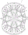
Fig. 2 is a structural view of a rotor in this embodiment.
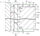
Fig. 3 is a cross-sectional view of the rotor in this embodiment.
Fig. 4 is a perspective view of the rotor in this embodiment.
Fig. 5 (a) to (c) are explanatory diagrams for explaining characteristics of the rotor in this embodiment.
Fig. 6 is a structural view of a rotor in which a part of the shape is changed in this embodiment.
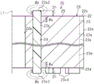
Fig. 7 is a cross-sectional view of a rotor in which a part of the shape is changed in this embodiment.
Fig. 8 is a perspective view of a rotor in which a part of the shape is changed in this embodiment.
Fig. 9 (a) to (c) are explanatory diagrams for explaining the characteristics of the rotor in which a part of the shape is changed in this embodiment.
Fig. 10 is a cross-sectional view of a rotor in a modification.
Fig. 11 is a cross-sectional view of a rotor in a modification.
Fig. 12 is a cross-sectional view of a rotor in a modification.
Fig. 13 is a cross-sectional view of a rotor in a modification.
Fig. 14 is a cross-sectional view of a rotor in a modification.
Fig. 15 is a cross-sectional view of a rotor in a modification.
Fig. 16 is a cross-sectional view of a rotor in a modification.
Fig. 17 is a cross-sectional view of a rotor in a modification.
Fig. 18 is a cross-sectional view of a rotor in a modification.
Fig. 19 is a cross-sectional view of a rotor in a modification.
Fig. 20 is a cross-sectional view of a rotor in a modification.
Fig. 21 is a cross-sectional view of a rotor in a modification.
Fig. 22 is a cross-sectional view of a rotor in a modification.
Fig. 23 is a cross-sectional view of a rotor in a modification.
Fig. 24 is a cross-sectional view of a rotor in a modification.
Fig. 25 is a cross-sectional view of a rotor in a modification.
Fig. 26 is a perspective view of a rotor in a modification.
Fig. 27 is a cross-sectional view of a rotor in a modification.
Fig. 28 is an explanatory diagram for explaining characteristics of the rotor in the embodiment.
Fig. 29 is a perspective view of a rotor in a modification.
Fig. 30 is an explanatory diagram for explaining characteristics of the rotor in this modification.
Detailed Description
Hereinafter, an apparatus for manufacturing a rotor, a method for manufacturing a rotor, and an embodiment of a rotor will be described.
The rotating electric machine M of the present embodiment shown in fig. 1 is constituted by a brushless motor of a buried magnet type. The rotating electrical machine M includes: a substantially annular stator 10; and a substantially cylindrical rotor 20 rotatably disposed in a space radially inside the stator 10.
The stator 10 includes a substantially annular stator core 11. The stator core 11 is made of a magnetic metal material. The stator core 11 is configured by, for example, stacking a plurality of electromagnetic steel plates along the axis L1 (see fig. 3). In the present embodiment, the stator core 11 has twelve pole teeth 12 extending radially inward and arranged at equal intervals in the circumferential direction. The teeth 12 are identical in shape to each other. The tip end portion, i.e., the radially inner end portion of the pole tooth 12 is substantially T-shaped, and the tip end surface 12a is arcuate along the outer peripheral surface of the rotor 20. The winding 13 is wound around the tooth 12 in a concentrated winding manner. The windings 13 are three-phase wires, and as shown in fig. 1, function as U-phase, V-phase, and W-phase, respectively. When power is supplied to the winding 13, a rotating magnetic field for driving the rotor 20 to rotate is generated in the stator 10. The outer peripheral surface of the stator core 11 of the stator 10 as described above is fixed with respect to the inner peripheral surface of the housing 14.
In the present embodiment, the rotor 20 includes: a rotation shaft 21; a substantially cylindrical rotor core 22 having a rotary shaft 21 inserted into a center portion thereof; and eight permanent magnets 23 in the form of being buried inside the rotor core 22. The rotor core 22 is made of a magnetic metal material. The rotor core 22 is configured by, for example, stacking a plurality of electromagnetic steel plates in the direction of the axis L1 shown in fig. 3. The rotor 20 is rotatably disposed with respect to the stator 10 by supporting a rotary shaft 21 on a bearing, not shown, provided in the housing 14.
The rotor core 22 has a magnet accommodating hole 24 for accommodating the permanent magnet 23. In the present embodiment, eight magnet housing holes 24 are provided at equal intervals in the circumferential direction of the rotor core 22. The magnet housing holes 24 have a convex substantially V-shaped folded shape protruding inward in the radial direction, and are formed in the same shape as each other. The magnet housing hole 24 is provided in the entire axial direction of the rotor core 22.
Here, the permanent magnet 23 of the present embodiment is constituted by a bonded magnet formed by molding and hardening a magnet material obtained by mixing a magnet powder with a resin. That is, the permanent magnet 23 is configured by setting the magnet accommodating hole 24 of the rotor core 22 as a molding die, filling the magnet material before curing into the magnet accommodating hole 24 without gaps by injection molding, and curing the magnet material in the magnet accommodating hole 24 after filling. Therefore, the hole shape of the magnet housing hole 24 becomes the outer shape of the permanent magnet 23. The permanent magnet 23 of the present embodiment is configured to protrude from the axial end surfaces 22c and 22d of the rotor core 22 (see fig. 3, etc.). The permanent magnet 23 has an embedded magnet portion 23m located in the magnet housing hole 24 and protruding portions 23x1, 23y1 protruding from the axial end faces 22c, 22d of the rotor core 22. The protruding portions 23x1, 23y1 of the permanent magnet 23 can be easily realized by providing recesses for forming the protruding portions 23x1, 23y1 in a not-shown forming die for closing the magnet housing holes 24 opened in the axial end faces 22c, 22d of the rotor core 22. As the magnet powder used for the permanent magnet 23 of the present embodiment, for example, a samarium iron nitrogen (SmFeN) magnet is used, but other rare earth magnets may be used.
The permanent magnet 23 has a convex substantially V-shaped folded shape protruding toward the radially inner side. In detail, as shown in fig. 2, the permanent magnet 23 has a shape in which radially inner end portions of a pair of straight portions 23a are connected to each other by a curved portion 23 b. The radially outer end 23c of the linear portion 23a is located near the outer peripheral surface 22a of the rotor core 22. The thickness Wm of the permanent magnet 23 is set constant at any one of V-shaped paths including a pair of straight portions 23a and curved portions 23 b. The permanent magnets 23 are line-symmetrical with respect to a circumferential center line Ls itself passing through the axial center O1 of the rotor 20, and are close to a magnetic pole boundary line Ld passing through the axial center O1 of the rotor 20 between adjacent permanent magnets 23. The angle between adjacent magnetic pole boundary lines Ld, that is, the magnetic pole opening angle θm of the rotor magnetic pole portion 26 including the permanent magnet 23 is an electrical angle of 180 °.
Here, the magnetic pole pitch Lp is set between the intersection point of the extension line of the inner side surface of each linear portion 23a of the V-shaped permanent magnet 23 and the outer circumferential surface 22a of the rotor core 22, and the distance from the outer circumferential surface 22a of the rotor core 22 to the inner side surface of the curved portion 23b on the circumferential center line Ls of the permanent magnet 23 is set to the embedding depth Lm. The permanent magnet 23 of the present embodiment is set to a deep folded shape such that the embedding depth Lm is larger than the pole pitch Lp. That is, the magnet surface 23d of the permanent magnet 23 of the present embodiment, which is formed by the inner side surfaces of the straight portions 23a and the curved portions 23b, is set to be larger than a well-known surface magnet type magnet surface (not shown). Further, by setting the embedding depth Lm to be large, the bent portion 23b of the permanent magnet 23 is located near the inner side in the radial direction of the shaft insertion hole 22b in which the rotary shaft 21 is inserted near the center portion of the rotor core 22. The folded shape of the permanent magnet 23 is an example, and can be changed to a substantially U-shaped folded shape having a shallow embedding depth Lm or a large bent portion 23b, as appropriate.
As shown in fig. 3 and 4, the permanent magnet 23 is provided in the entire axial direction of the rotor core 22. The axial end surfaces 22c, 22d of the rotor core 22 are formed as flat surfaces, and the permanent magnet 23 has protruding portions 23x1, 23y1 protruding in the axial direction from the axial end surfaces 22c, 22d of the rotor core 22. The protruding portions 23x1, 23y1 are continuous in a V-shaped path including the straight portion 23a and the curved portion 23b of the permanent magnet 23, and have a constant thickness Wm. The protruding portions 23x1, 23y1 are provided on one axial end surface 22c and the other axial end surface 22d of the rotor core 22, respectively. The protruding portions 23x1, 23y1 are integrally and continuously formed of the same material as the embedded magnet portion 23m of the permanent magnet 23 located in the magnet housing hole 24 of the rotor core 22.
The protruding portions 23x1, 23y1 of the permanent magnet 23 are end portions of the permanent magnet 23 located on the axial end faces 22c, 22d of the rotor core 22, and function so that the leakage magnetic flux Φb shown in fig. 3, which is easily generated at the end portions of the permanent magnet 23, is generated at the portion. In other words, a larger portion of the magnetic flux of the embedded magnet portion 23M in the rotor core 22 of the permanent magnet 23 flows in the radial direction without leaking to the outside from the axial end faces 22c, 22d, and the larger portion of the magnetic flux becomes the effective magnetic flux Φa contributing to the torque of the rotating electrical machine M. The protruding portions 23x1, 23y1 are set to protrude from the axial end faces 22c, 22D of the rotor core 22 by an appropriate protruding amount D1 while achieving an increase in the effective magnetic flux Φa. The protruding amounts D1 of the protruding portions 23x1, 23y1 may be different from the actual size in the drawings.
After the magnet material is cured, the permanent magnet 23 mainly provided in the magnet accommodating hole 24 of the rotor core 22 is magnetized from the outside of the rotor core 22 by a magnetization device, not shown, to function as an original magnet. In the present embodiment, the permanent magnets 23 are provided with eight magnets in the circumferential direction of the rotor core 22, and are magnetized so that polarities are alternately different in the circumferential direction. In addition, each permanent magnet 23 is magnetized in the thickness direction thereof.
The portion of the rotor core 22 located inside the V-shaped fold-back shape of the permanent magnet 23 and radially outside the permanent magnet 23 functions as an outer core portion 25 that faces the stator 10 and is used to obtain reluctance torque. The outer core portion 25 has a substantially triangular shape with one apex directed toward the center of the rotor 20 when viewed in the axial direction. In the present embodiment, the rotor 20 includes the permanent magnets 23 and the outer core portions 25 surrounded by the inner sides of the V-shapes of the permanent magnets 23, and is configured as the eight-pole rotor magnetic pole portions 26. As shown in fig. 1, each of the rotor magnetic pole portions 26 alternately functions as an N pole and an S pole in the circumferential direction. In the rotor 20 having such a rotor magnetic pole portion 26, the magnet torque and the reluctance torque can be appropriately obtained.
The operation of the rotor 20 of the rotating electrical machine M of the present embodiment will be described.
In the structure of the rotor 20 of the present embodiment, the permanent magnets 23 in the form of being embedded in the rotor core 22 have the end portions of the permanent magnets 23 protruding from the axial end surfaces 22c, 22d on both sides of the rotor core 22 as protruding portions 23x1, 23y1, respectively. By setting the end portions of the permanent magnet 23 as the protruding portions 23x1, 23y1, the leakage magnetic flux Φb generated at the end portions of the permanent magnet 23 is concentrated in the protruding portions 23x1, 23y1. In addition, in the embedded magnet portion 23m of the permanent magnet 23 located in the rotor core 22, the path length of the magnetic flux becomes longer because the path of the magnetic flux to be leaked from the axial end surfaces 22c, 22d of the rotor core 22 passes over the protruding portions 23x1, 23y1. Therefore, leakage of the magnetic flux in the embedded magnet portion 23m from the axial end faces 22c, 22d of the rotor core 22 can be suppressed, and the magnetic flux generated in the embedded magnet portion 23m flows in the rotor core 22 in the radial direction over the entire axial direction. In this way, the magnetic flux generated in the entire axial direction of the embedded magnet portion 23M becomes the effective magnetic flux Φa contributing to the torque of the rotating electrical machine M in large quantity, and the magnetic flux of the effective magnetic flux Φa can be increased.
Fig. 5 (a) shows the comparison result between the present embodiment and the comparative example. In the present embodiment, the end portions of the permanent magnets 23 are projected as the projecting portions 23x1, 23y1 from the axial end surfaces 22c, 22d on both sides of the rotor core 22. The comparative example is a conventional well-known structure in which the end portions of the permanent magnets 23 do not protrude from the axial end faces 22c, 22d of the rotor core 22. Fig. 5 (a) shows a comparison between the induction voltage Vm generated in the rotating electric machine M and the induction voltage/magnet volume (Vm/Va) obtained by dividing the induction voltage by the volume of the permanent magnet 23, and the present embodiment when the comparative example is 100.
The induced voltage Vm is sufficiently larger in this embodiment than in the comparative example. This is because the leakage magnetic flux Φb is generated in the protruding portions 23x1 and 23y1, and therefore the magnetic flux of the embedded magnet portion 23m of the permanent magnet 23 is often the effective magnetic flux Φa, and the effective magnetic flux Φa is increased. As shown in the relation between the protrusion amounts D1 of the protrusions 23x1 and 23y1 and the induced voltage Vm in fig. 5 (b), it is clear that the effective magnetic flux Φa increases and the induced voltage Vm also increases because the protrusion amount D1 of the protrusions 23x1 and 23y1 is zero or more, that is, protrudes. On the other hand, the induced voltage/magnet volume (Vm/Va) is smaller than that of the comparative example because the protrusions 23x1 and 23y are provided to increase the magnet volume Va correspondingly. As shown in the relation between the protrusion amount D1 and the induced voltage/magnet volume (Vm/Va) in fig. 5 (c), it is seen that the Vm/Va value gradually decreases due to the increase in the magnet volume Va caused by the protrusion of the protruding portions 23x1, 23y1. The protruding amount D1 is appropriately set in consideration of the relationship between the protruding amount D1 of the protruding portions 23x1, 23y1, the induced voltage Vm, and the induced voltage/magnet volume (Vm/Va). Further, since the increase in the protruding amount D1 is also associated with an increase in the weight of the rotor 20, an increase in the magnet material of the permanent magnet 23, and the like, it is preferable to set the protruding amount D1.
Incidentally, in the above, the protruding portions 23x1, 23y1 of the permanent magnet 23 are continuous and the thickness Wm is constant in the V-shaped path including the straight portion 23a and the bent portion 23b of the permanent magnet 23, but as shown in fig. 6, 7 and 8, a structure in which the thickness Wm1 of the bent portion 23b of the permanent magnet 23 is made narrower than the thickness Wm of the straight portion 23a has also been studied.
Fig. 9 (a) shows the result of comparison between the embodiment and the comparative example in which the thickness Wm1 of the bent portion 23b is slightly narrower.
The present embodiment is larger than the comparative example with respect to either the induced voltage Vm or the induced voltage/magnet volume (Vm/Va). The greater the thickness of the protruding portions 23x1, 23y1, the longer the path length of the magnetic flux of the embedded magnet portion 23m of the permanent magnet 23 leaking from the axial end faces 22c, 22d of the rotor core 22 can be, and the more leakage of the magnetic flux can be suppressed, but the curved portion 23b of the permanent magnet 23 is a portion where the leakage of the magnetic flux is smaller than the linear portion 23a, and therefore the thickness Wm1 of the curved portion 23b can be adjusted to be slightly narrower. In other words, the thickness Wm1 of the curved portion 23b of the permanent magnet 23 is changed appropriately so that the Vm value and the Vm/Va value are both larger than those of the comparative example. As a relation between the protrusion amount D1 of the protruding portions 23x1, 23y1 and the induced voltage Vm shown in fig. 9 (b), when the protrusion amount D1 of the protruding portions 23x1, 23y1 is zero or more, the Vm value increases with an increase in the effective magnetic flux Φa, but in this embodiment, the change to the highest point is advanced. On the other hand, as a relation between the protrusion amount D1 and the induced voltage/magnet volume (Vm/Va) shown in fig. 9 (c), the Vm/Va value temporarily increases and gradually decreases even when the protrusion amount D1 of the protruding portions 23x1, 23y1 is zero or more due to the decrease in the magnet volume Va caused by the narrow thickness Wm1 of the bent portion 23 b. This is a result of reducing the weight of the permanent magnet 23 as much as possible while preventing the magnetic flux of the embedded magnet portion 23m of the permanent magnet 23 from leaking out of the axial end faces 22c, 22d of the rotor core 22 as much as possible.
Effects of the present embodiment will be described.
(1) Since the end portions of the permanent magnets 23 protrude from the axial end surfaces 22c, 22d forming the flat surfaces of the rotor core 22 as the protruding portions 23x1, 23y1, the magnetic flux of the embedded magnet portions 23m of the permanent magnets 23 located in the rotor core 22 is required to pass over the protruding portions 23x1, 23y1 to leak from the axial end surfaces 22c, 22d of the rotor core 22. That is, since the path length of the magnetic flux of the embedded magnet portion 23m to leak becomes long, the leakage of the magnetic flux of the embedded magnet portion 23m can be suppressed. Since the magnetic flux of the embedded magnet portion 23M of the permanent magnet 23 becomes the effective magnetic flux Φa contributing to the torque of the rotating electrical machine M, the improvement of the torque performance of the rotating electrical machine M can be sufficiently expected by increasing the magnetic flux of the effective magnetic flux Φa without leaking out as much as possible. The axial end surfaces 22c and 22d of the rotor core 22 are generally flat, and can be realized by a simple process of projecting only the end portions of the permanent magnets 23 from the axial end surfaces 22c and 22d of the rotor core 22.
(2) Since the protruding portions 23x1, 23y1 of the permanent magnet 23 have the same protruding shape from the axial end surfaces 22c, 22d on both sides of the rotor core 22, an effect of maintaining the weight balance of the rotor 20 can be obtained satisfactorily.
(3) Since the protruding portions 23x1, 23y1 of the permanent magnet 23 are continuously provided in the extending direction of the V-shape of the permanent magnet 23 along the axial end faces 22c, 22d of the rotor core 22, leakage of the magnetic flux of the buried magnet portion 23m contributing to the torque can be more reliably suppressed over the entire range of the permanent magnet 23.
(4) Since the protruding portions 23x1, 23y1 of the permanent magnet 23 are provided so that the protruding amount D1 protruding from the axial end faces 22c, 22D of the rotor core 22 is constant, leakage of the magnetic flux of the embedded magnet portion 23m contributing to the torque can be suppressed equally at each portion.
(5) Since the protruding portions 23x1, 23y1 of the permanent magnet 23 are integrally provided continuously from the embedded magnet portion 23m of the rotor core 22, they can be easily formed by simultaneously forming the same material or the like.
(6) Since the protruding portions 23x1, 23y1 of the permanent magnets 23 are provided for all the permanent magnets 23 arranged along the circumferential direction of the rotor 20, leakage of the magnetic flux of the buried magnet portion 23m contributing to the torque can be suppressed in all the permanent magnets 23. In addition, the weight balance of the rotor 20 can be maintained satisfactorily.
The present embodiment can be modified and implemented as follows. The present embodiment and the following modifications can be combined and implemented within a range that is not technically contradictory.
The configuration of the protruding portions 23x1, 23y1 of the end portions of the permanent magnet 23 protruding from the axial end faces 22c, 22d of the rotor core 22 may be changed as appropriate.
For example, a protruding portion may be provided locally in a V-shaped path of the permanent magnet 23 including the straight portion 23a and the curved portion 23 b.
As shown in fig. 10, protruding portions 23x2, 23y2 protruding only in the bent portion 23b of the permanent magnet 23 may be provided. The protruding portions 23x2, 23y2 are similarly provided on both the axial end faces 22c, 22d of the rotor core 22.
As shown in fig. 11, protruding portions 23x3, 23y3 protruding only in the straight portion 23a of the permanent magnet 23 may be provided. The protruding portions 23x3, 23y3 are similarly provided on both the axial end faces 22c, 22d of the rotor core 22.
As shown in fig. 12, protruding portions 23x2, 23y2 protruding in the curved portion 23b of the permanent magnet 23 and protruding portions 23x4, 23y4 partially protruding in the extending direction of the straight portion 23a may be provided. Projections 23x2, 23y2 and projections 23x4, 23y4 are provided on both axial end surfaces 22c, 22d of rotor core 22 in the same manner.
Although not particularly shown, the protruding portion of the permanent magnet 23 may be provided only on one side of the V-shape, as in the case of half of the straight portion 23a and the curved portion 23b on one side of the V-shape of the permanent magnet 23.
In this way, the magnet material of the permanent magnet 23 can be reduced, and the effect of reducing the weight of the rotor 20 can be expected.
For example, protruding portions having different structures may be provided on the axial end surfaces 22c and 22d of the rotor core 22. First, a method is described in which a protruding portion is provided only on one side of the axial end surfaces 22c and 22d of the rotor core 22.
As shown in fig. 13, the protruding portion 23x1 may be provided only on the axial end surface 22c side of the rotor core 22. In addition, the protruding portion 23x1 continues along the V-shaped path of the permanent magnet 23 as described above.
As shown in fig. 14, a protruding portion 23x2 protruding only in the bent portion 23b of the permanent magnet 23 may be provided only on the axial end surface 22c side of the rotor core 22.
As shown in fig. 15, a protruding portion 23x3 protruding only in the linear portion 23a of the permanent magnet 23 may be provided only on the axial end surface 22c side of the rotor core 22.
As shown in fig. 16, only the protruding portion 23x2 protruding in the bent portion 23b of the permanent magnet 23 and the protruding portion 23x4 partially protruding in the extending direction of the straight portion 23a may be provided on the axial end surface 22c side of the rotor core 22.
In this way, the magnet material of the permanent magnet 23 can be reduced, and the effect of reducing the weight of the rotor 20 can be expected.
In the following, a configuration in which protruding portions are provided on the axial end faces 22c and 22d of the rotor core 22, respectively, is described.
As shown in fig. 17, a protrusion 23x2 protruding only in the bent portion 23b of the permanent magnet 23 may be provided on the axial end surface 22c side of the rotor core 22, and a protrusion 23y2 protruding in the bent portion 23b of the permanent magnet 23 and a protrusion 23y4 partially protruding in the extending direction of the linear portion 23a may be provided on the axial end surface 22d side of the rotor core 22.
As shown in fig. 18, a projection 23x1 continuous along the V-shaped path of the permanent magnet 23 may be provided on the axial end surface 22c side of the rotor core 22, and a projection 23y3 projecting only on the linear portion 23a of the permanent magnet 23 may be provided on the axial end surface 22d side of the rotor core 22.
As shown in fig. 19, on the axial end surface 22c side of the rotor core 22, a protruding portion 23x2 protruding in the bent portion 23b of the permanent magnet 23 and a protruding portion 23x4 partially protruding in the extending direction of the straight portion 23a may be provided, and on the axial end surface 22d side of the rotor core 22, a protruding portion 23y1 continuous along the V-shaped path of the permanent magnet 23 may be provided.
In this way, the degree of freedom of the outer shape of the rotor 20 including the protruding shape of the permanent magnet 23 can be expected to be improved.
Further, for example, a protruding portion may be provided locally in the thickness direction orthogonal to the extending direction of the V-shaped path of the permanent magnet 23.
As shown in fig. 20, the permanent magnet 23 may have narrow protruding portions 23x5 and 23y5 at the center in the thickness direction. The protruding portions 23x5, 23y5 are continuous along the V-shaped path of the permanent magnet 23. The protruding portions 23x5, 23y5 are similarly provided on both the axial end surfaces 22c, 22d of the rotor core 22.
As shown in fig. 21, protruding portions 23x6, 23y6 having a groove portion 23z1 may be provided at the center portion in the thickness direction of the permanent magnet 23. The groove 23z1 has the same depth as the protruding amount D1 of the protruding portions 23x6, 23y6. The protruding portions 23x6, 23y6 are continuous along the V-shaped path of the permanent magnet 23. The protruding portions 23x6 and 23y6 are similarly provided on both the axial end surfaces 22c and 22d of the rotor core 22.
As shown in fig. 22, the depth of the groove 23z2 provided at the central portion in the thickness direction of the protruding portions 23x6, 23y6 of the permanent magnet 23 may be different from the protruding amount D1 of the protruding portions 23x6, 23y6. As shown in fig. 22, the groove 23z2 may be shallower than the protruding amount D1 of the protruding portions 23x6 and 23y6, or may be deeper than the protruding amount D1.
In this way, the magnet material of the permanent magnet 23 can be reduced, and the effect of reducing the weight of the rotor 20 can be expected.
In addition, for example, the shape of the protruding portion provided to the permanent magnet 23 may be changed. The protruding amount D1 may be changed according to the position of the protruding portion.
As shown in fig. 23, the protruding portions 23x7, 23y7 provided in the curved portion 23b of the permanent magnet 23 may be formed in an inclined surface shape. The protruding portions 23x7, 23y7 are formed of a slope shape having a V-shape of the permanent magnet 23 with a higher inner side and a lower outer side. The protruding portions 23x7, 23y7 are similarly provided on both the axial end faces 22c, 22d of the rotor core 22.
As shown in fig. 24, the protruding portions 23x8, 23y8 continuous in the extending direction of the V-shaped path of the permanent magnet 23 may have a slope shape in which the portion of the curved portion 23b is the highest and gradually decreases from the curved portion 23b toward the radially outer end portion 23c of the linear portion 23 a. The protruding portions 23x8, 23y8 are similarly provided on both the axial end faces 22c, 22d of the rotor core 22.
In this way, the magnet material of the permanent magnet 23 can be reduced, and the effect of reducing the weight of the rotor 20 can be expected. Further, it is expected to improve the degree of freedom of the outer shape of the rotor 20 including the protruding shape of the permanent magnet 23.
In addition, for example, the protruding portion of the permanent magnet 23 may be provided separately from the embedded magnet portion 23 m. In this case, the magnet materials may be different from each other.
As shown in fig. 25, the protruding portions 23x9, 23y9 of the permanent magnet 23 are continuous in the extending direction of the V-shaped path, and are similarly provided to both the axial end faces 22c, 22d of the rotor core 22. The protruding portions 23x9 and 23y9 may be made of a less expensive magnet material than the embedded magnet portion 23 m. The protruding portions 23x9 and 23y9 may be made of a different magnetic material from the embedded magnet portion 23 m. The protruding portions 23x9 and 23y9 may be made of a magnet material having a strength different from that of the embedded magnet portion 23m, and may have a high strength in consideration of exposure from the axial end surfaces 22c and 22d of the rotor core 22. The protruding portions 23x9 and 23y9 may be formed simultaneously with the embedded magnet portion 23m, or may be added later.
In this way, the effect of improving the degree of freedom of the structure of the permanent magnet 23 and the like can be expected.
For example, the protruding portions protruding from the axial end surfaces 22c and 22d of the rotor core 22 may not be provided in all the permanent magnets 23 arranged in the circumferential direction of the rotor 20.
As shown in fig. 26, the protruding portions 23x1 may be selectively provided in a plurality of permanent magnets 23 arranged in the circumferential direction so as to be placed one by one. The substrates may be placed at equal intervals other than one, or may be placed at unequal intervals.
In this way, the magnet material of the permanent magnet 23 can be reduced, and the effect of reducing the weight of the rotor 20 can be expected.
As shown in fig. 27, a recess 24a may be provided around the opening of the magnet housing hole 24 on the axial end surfaces 22c, 22d of the rotor core 22, and the recess 24a may accumulate the remaining portion of the magnet material when the permanent magnet 23 including the protruding portions 23x1, 23y1 is molded. In this way, since the remaining portion of the magnet material can be accommodated in the recess 24a, the remaining portion of the magnet material can be suppressed from protruding as burrs of the permanent magnet 23 on the axial end surfaces 22c, 22d of the rotor core 22.
The permanent magnet 23 is not limited to the V-shape, and may have other convex folded shapes such as a U-shape protruding radially inward of the rotor 20. In addition, the shape may be other than a folded shape such as an I-shape.
The permanent magnet 23 is formed by injection molding a magnet material in the magnet accommodating hole 24 of the rotor core 22, but the permanent magnet 23 may be manufactured in advance and fixed by being inserted into the magnet accommodating hole 24 of the rotor core 22.
In addition to the above, the structure of the rotor 20 and the structure of the rotating electrical machine M may be appropriately changed.
Fig. 28 is a graph comparing the magnitude of the induced voltage Vm generated in the rotating electric machine M in the comparison structure 1, the comparison structure 2, and the above embodiment. In the above embodiment, the axial length of the stator core 11 is set to be equal to the axial length of the rotor core 22. The axial length of the stator core 11 is, for example, the axial length of the tip end surface 12a of the pole tooth 12. In addition, as mentioned in the above embodiment, the axial length of the permanent magnet 23 is formed longer than the axial length of the rotor core 22, thereby forming the protruding portions 23x1, 23y1. That is, in the above embodiment, the axial length of the permanent magnet 23 is longer than the axial lengths of the rotor core 22 and the stator core 11. The protruding portions 23x1, 23y1 of the permanent magnet 23 are located on the axial side of the axial end surfaces of the stator core 11.
In contrast to the above embodiment, the comparative structure 1 is configured such that the axial lengths of the permanent magnet 23, the rotor core 22, and the stator core 11 are equal to each other.
In comparative structure 2, the axial length of permanent magnet 23 is set equal to the axial length of rotor core 22. That is, in the comparative structure 2, the permanent magnet 23 is not formed at a portion protruding in the axial direction from the magnet accommodating hole 24. In the comparative structure 2, the axial length of the rotor core 22 and the permanent magnet 23 is set to be longer than the axial length of the stator core 11.
As shown in fig. 28, in the comparative structure 2 and the above embodiment, the induced voltage Vm increases with respect to the comparative structure 1. This is considered to be because the axial entirety of the stator core 11 is contained within the axial range of the permanent magnet 23.
In the comparative structure 2 and the above embodiment, the magnitude of the induced voltage Vm is substantially equal. In the above embodiment, the axial length of the rotor core 22 is equal to the axial length of the stator core 11, and only the axial length of the permanent magnet 23 is long. Therefore, in the above embodiment, the axial length of the rotor core 22 can be shortened with respect to the comparative structure 2. Therefore, as in the above embodiment, by making the axial length of the permanent magnet 23 longer than the axial lengths of the rotor core 22 and the stator core 11, it is possible to increase the induced voltage Vm and to contribute to weight reduction of the rotor core 22 and the rotating electrical machine M.
In the above embodiment, the rotor core 22 is formed of a single member, but in addition to this, the rotor core 22 may be formed of a plurality of rotor core portions arranged in the axial direction, for example. For example, in the structure shown in fig. 29, the rotor core 22 is constituted by two rotor core portions arranged in an axial direction. In the following description, one of the two rotor core portions is referred to as a first rotor core portion 31, and the other is referred to as a second rotor core portion 32. In the structure shown in fig. 29, the same reference numerals as those in the above-described embodiment may be given to the same structures as those in the above-described embodiment, and detailed description thereof may be omitted.
As shown in fig. 29, the rotor 20 includes a rotary shaft 21, a first rotor portion R1 having a first rotor core portion 31, and a second rotor portion R2 having a second rotor core portion 32.
The first rotor portion R1 and the second rotor portion R2 are arranged in a direction along the axis L1 of the rotor 20. The first rotor portion R1 and the second rotor portion R2 are configured to be rotatable integrally with the rotary shaft 21. The rotary shaft 21 is supported by a bearing, not shown, provided in the housing 14, and the first rotor R1 and the second rotor R2 are rotatably disposed with respect to the stator 10.
The first rotor core portion 31 has a substantially cylindrical shape with the rotary shaft 21 inserted in the center portion. The second rotor core portion 32 is also substantially cylindrical with the rotary shaft 21 inserted in the center portion in the same manner. The first rotor portion R1 includes the permanent magnet 23 buried in the first rotor core portion 31. In addition, the second rotor portion R2 includes the permanent magnets 23 buried in the second rotor core portion 32.
The first rotor core portion 31 and the second rotor core portion 32 are members of the same structure, for example. The first rotor core portion 31 and the second rotor core portion 32 are each composed of a magnetic metal material. The first rotor core portion 31 and the second rotor core portion 32 are each formed by stacking a plurality of electromagnetic steel plates along the axis L1, for example. The first rotor core portion 31 and the second rotor core portion 32 are arranged in an axial direction to constitute the rotor core 22.
In each of the first rotor core portion 31 and the second rotor core portion 32, the cross-sectional shape orthogonal to the axis L1 is, for example, the same as the cross-sectional shape orthogonal to the axis L1 in the rotor core 22 of the above embodiment. That is, the first rotor core portion 31 and the second rotor core portion 32 each have a magnet accommodating hole 24 for accommodating the permanent magnet 23. In each of the first rotor core portion 31 and the second rotor core portion 32, the number and the shape of the magnet accommodating holes 24 in the circumferential direction are the same as those of the magnet accommodating holes 24 of the above embodiment, for example.
In each of the first rotor core portion 31 and the second rotor core portion 32, a portion located inside the V-shaped folded shape of the permanent magnet 23 and located radially outside the permanent magnet 23 functions as an outer core portion 25 that faces the stator 10 and is used to obtain reluctance torque. Further, the first rotor portion R1 and the second rotor portion R2 have eight rotor magnetic pole portions 26 including the permanent magnets 23 and the outer core portions 25, respectively. The rotor magnetic pole portions 26 alternately function as N poles and S poles in the circumferential direction.
In each of the first rotor portion R1 and the second rotor portion R2, each rotor magnetic pole portion 26 has a magnetic pole center C in the circumferential direction. The respective magnetic pole centers C are set at equal intervals in the circumferential direction. In this example, the respective magnetic pole centers C of the eight rotor magnetic pole portions 26 are set to be spaced 45 ° from each other in the circumferential direction. In each rotor magnetic pole portion 26, the magnetic pole center C coincides with the circumferential center line Ls of the permanent magnet 23.
The rotor magnetic pole portions 26 of the second rotor portion R2 are circumferentially offset with respect to the rotor magnetic pole portions 26 of the first rotor portion R1. In this example, the first rotor portion R1 and the second rotor portion R2 have the same structure, and the second rotor portion R2 is rotated by a predetermined angle with respect to the first rotor portion R1 to form a rotor 20. Thereby, the magnetic pole center C of the second rotor portion R2 is shifted from the magnetic pole center C of the first rotor portion R1 by a predetermined angle in the circumferential direction. Hereinafter, the angle at which the magnetic pole center C of the second rotor portion R2 is circumferentially offset from the magnetic pole center C of the first rotor portion R1 is referred to as a skew angle θ.
The skew angle θ of this example is set based on the following equation (a) when the number of poles of the rotor 20 is p and the least common multiple of the number of poles p and the number of slots of the stator 10 is L.
θ=180/L…(a)
The number of poles p of the rotor 20 is the number of rotor magnetic pole portions 26 in each of the first rotor portion R1 and the second rotor portion R2, in this example, eight poles. In this example, the number of slots is twelve. That is, the skew angle θ in this example is set to 7.5 ° which is obtained by substituting p=8 and l=24 in the formula (a).
Fig. 30 shows a relationship between the rotational angle of the rotor 20 and the magnitude of the cogging torque in a configuration in which the skew angle θ is set to 7.5 °. In the figure, the cogging torque generated in the first rotor R1 is denoted by T1, the cogging torque generated in the second rotor R2 is denoted by T2, and the resultant cogging torque generated in the rotor 20 as a whole in which the cogging torques T1 and T2 are combined is denoted by T3. When the skew angle θ is 7.5[ °, the cogging torque T1 and the cogging torque T2 are in opposite phases to each other. That is, in this case, the cogging torques T1 and T2 are canceled, and the resultant cogging torque T3 is reduced. In this way, by shifting the magnetic pole centers C of the first rotor portion R1 and the second rotor portion R2 in the circumferential direction, the resultant cogging torque T3 of the rotor 20 as a whole can be reduced. The value of the skew angle θ in this example is an example, and can be changed appropriately according to the structure of the rotating electrical machine M.
The rotor 20 of this example also has protruding portions 23x1, 23y1, which are portions of the permanent magnets 23 protruding in the axial direction from the rotor core 22, as in the above-described embodiment. The protruding portion 23x1 protrudes from one axial end surface 22c of the rotor core 22. In this example, an axial end face 22c of the rotor core 22 is an end face on the opposite side of the second rotor portion R2 in the first rotor core portion 31. The protruding portion 23x1 is a portion of the permanent magnet 23 of the first rotor portion R1. Further, the protruding portion 23y1 protrudes from the other axial end surface 22d of the rotor core 22. In this example, an axial end face 22d of the rotor core 22 is an end face on the opposite side of the first rotor portion R1 in the second rotor core portion 32. The protruding portion 23y1 is a portion of the permanent magnet 23 of the second rotor portion R2.
In the first rotor core portion 31, for example, the permanent magnet 23 does not protrude from an axial end face on the opposite side to the axial end face 22c where the protruding portion 23x1 is provided. In the second rotor core portion 32, for example, the permanent magnets 23 do not protrude from the axial end face on the opposite side to the axial end face 22d where the protruding portions 23y1 are provided. Further, the first rotor core portion 31 and the second rotor core portion 32 are arranged in such a manner that the respective axial end faces of the permanent magnets 23, which do not protrude, are axially opposed to each other. In this example, for example, the first rotor core portion 31 and the second rotor core portion 32 are arranged so that the axial end faces are in contact with each other.
In this example, the same effects as those of the above embodiment can be obtained by the protruding portions 23x1, 23y1.
In this example, the first rotor core portion 31 and the second rotor core portion 32 are configured such that the respective axial end surfaces of the permanent magnets 23 that do not protrude are in contact with each other, but the present invention is not limited thereto, and a gap may be provided between the axial end surfaces. The permanent magnets 23 may protrude from axially facing end surfaces of the first rotor core portion 31 and the second rotor core portion 32.
Symbol description
An M rotary electric machine, 10 stators, 20 rotors, 22 rotor cores, 22C, 22D axial end faces, 23 permanent magnets, 23M embedded magnet portions, 23x1 to 23x9, 23y1 to 23y9 protruding portions, 24 magnet housing holes, D1 protruding amount, R1 first rotor portion (rotor portion), R2 second rotor portion (rotor portion), 31 first rotor core portion (rotor core portion), 32 second rotor core portion (rotor core portion), C magnetic pole center.
Claims (17)
1. A rotor (20) has permanent magnets (23) in an embedded form embedded in a magnet accommodating hole (24) of a rotor core (22),
the axial end faces (22 c, 22 d) of the rotor core are formed as flat faces,
the permanent magnet is configured to have protruding portions (23 x 1-23 x9, 23y 1-23 y 9) at least a part of which protrudes from an axial end surface of the rotor core.
2. The rotor of claim 1, wherein the rotor comprises a plurality of rotor blades,
the permanent magnets have a convex folded shape protruding radially inward of the rotor.
3. A rotor according to claim 1 or 2, wherein,
the protruding portions of the permanent magnets are configured to have the same protruding shape from the axial end surfaces of both sides of the rotor core.
4. A rotor according to claim 1 or 2, wherein,
the protruding portions of the permanent magnets are formed in different protruding shapes from both axial end surfaces of the rotor core.
5. The rotor according to claim 1 to 4,
the protruding portions of the permanent magnets are continuously provided in the extending direction of the permanent magnets along the axial end face of the rotor core.
6. The rotor according to claim 1 to 4,
the protruding portion of the permanent magnet is provided locally in the extending direction of the permanent magnet along the axial end face of the rotor core.
7. The rotor according to claim 1 to 6,
the protruding portion of the permanent magnet is provided locally in a thickness direction orthogonal to an extending direction of the permanent magnet along an axial end face of the rotor core.
8. The rotor according to claim 1 to 7,
the protruding portion of the permanent magnet is provided so that the protruding amount (D1) protruding from the axial end face of the rotor core is constant.
9. The rotor according to claim 1 to 7,
the protruding portion of the permanent magnet is provided such that the protruding amount (D1) protruding from the axial end face of the rotor core differs depending on the location.
10. The rotor according to any one of claim 1 to 9, wherein,
the protruding portion of the permanent magnet is integrally and continuously provided with an embedded magnet portion (23 m) located in the magnet housing hole of the rotor core.
11. The rotor according to any one of claim 1 to 9, wherein,
the protruding portion of the permanent magnet is provided separately from an embedded magnet portion (23 m) located in the magnet housing hole of the rotor core.
12. The rotor according to any one of claim 1 to 11,
the permanent magnets are arranged in plurality in the circumferential direction of the rotor,
the protruding portion of the permanent magnet is provided for all the permanent magnets arranged along the circumferential direction of the rotor.
13. The rotor according to any one of claim 1 to 11,
the permanent magnets are arranged in plurality in the circumferential direction of the rotor,
the protruding portion of the permanent magnet is selectively provided for the permanent magnet arranged along the circumferential direction of the rotor.
14. The rotor according to any one of claim 1 to 13, wherein,
the permanent magnet is formed by filling a magnet material into the magnet accommodating hole of the rotor core and hardening the magnet material in the magnet accommodating hole.
15. The rotor according to any one of claim 1 to 14, wherein,
the rotor comprises a plurality of rotor parts (R1, R2) arranged in an axial direction,
the plurality of rotor parts each have a rotor core part (31, 32) constituting the rotor core and the permanent magnets buried in the rotor core part,
the magnetic pole center (C) of at least one of the plurality of rotor sections is circumferentially offset with respect to the magnetic pole center (C) of the other rotor section.
16. A rotating electrical machine (M) comprising:
a rotor (20) having permanent magnets (23) in an embedded form embedded in a magnet accommodating hole (24) of a rotor core (22); and
a stator (10) that applies a rotating magnetic field to the rotor,
the axial end faces (22 c, 22 d) of the rotor core are formed as flat faces,
the permanent magnet has protruding portions (23 x1 to 23x9, 23y1 to 23y 9) at least a part of which protrudes from an axial end surface of the rotor core, and the rotor is configured.
17. The rotating electrical machine according to claim 16, wherein,
the rotor comprises a plurality of rotor parts (R1, R2) arranged in an axial direction,
the plurality of rotor parts each have a rotor core part (31, 32) constituting the rotor core and the permanent magnets buried in the rotor core part,
the magnetic pole center (C) of at least one of the plurality of rotor sections is circumferentially offset with respect to the magnetic pole center (C) of the other rotor section.
Applications Claiming Priority (5)
| Application Number | Priority Date | Filing Date | Title |
|---|---|---|---|
| JP2020-173869 | 2020-10-15 | ||
| JP2020173869 | 2020-10-15 | ||
| PCT/JP2021/030888 WO2022080010A1 (en) | 2020-10-15 | 2021-08-24 | Rotor and rotating electric machine |
| JPPCT/JP2021/030888 | 2021-08-24 | ||
| PCT/JP2021/034893 WO2022080110A1 (en) | 2020-10-15 | 2021-09-22 | Rotor and rotary electric machine |
Publications (1)
| Publication Number | Publication Date |
|---|---|
| CN116325432A true CN116325432A (en) | 2023-06-23 |
Family
ID=81207912
Family Applications (1)
| Application Number | Title | Priority Date | Filing Date |
|---|---|---|---|
| CN202180070021.9A Pending CN116325432A (en) | 2020-10-15 | 2021-09-22 | Rotor and rotating electrical machine |
Country Status (5)
| Country | Link |
|---|---|
| US (1) | US20230246496A1 (en) |
| JP (1) | JPWO2022080110A1 (en) |
| CN (1) | CN116325432A (en) |
| DE (1) | DE112021005414T5 (en) |
| WO (1) | WO2022080110A1 (en) |
Family Cites Families (7)
| Publication number | Priority date | Publication date | Assignee | Title |
|---|---|---|---|---|
| JPH11136888A (en) * | 1997-10-28 | 1999-05-21 | Toshiba Corp | Permanent magnet motor and manufacture thereof |
| JP2013051837A (en) * | 2011-08-31 | 2013-03-14 | Daikin Ind Ltd | Rotary electric machine |
| JP2016072995A (en) | 2014-09-26 | 2016-05-09 | パナソニックIpマネジメント株式会社 | Embedded magnet type rotor and electric motor including the same |
| JP6249417B2 (en) * | 2015-03-09 | 2017-12-20 | 三菱電機株式会社 | Rotating electric machine and electric power steering device |
| CN106469953A (en) * | 2015-08-18 | 2017-03-01 | 珠海格力节能环保制冷技术研究中心有限公司 | A kind of motor and its rotor |
| JP2017070031A (en) * | 2015-09-29 | 2017-04-06 | ダイキン工業株式会社 | Rotor |
| WO2018198866A1 (en) * | 2017-04-24 | 2018-11-01 | パナソニックIpマネジメント株式会社 | Electric motor element, electric motor, and device |
-
2021
- 2021-09-22 DE DE112021005414.7T patent/DE112021005414T5/en active Pending
- 2021-09-22 CN CN202180070021.9A patent/CN116325432A/en active Pending
- 2021-09-22 JP JP2022557323A patent/JPWO2022080110A1/ja active Pending
- 2021-09-22 WO PCT/JP2021/034893 patent/WO2022080110A1/en active Application Filing
-
2023
- 2023-04-11 US US18/133,151 patent/US20230246496A1/en active Pending
Also Published As
| Publication number | Publication date |
|---|---|
| JPWO2022080110A1 (en) | 2022-04-21 |
| WO2022080110A1 (en) | 2022-04-21 |
| DE112021005414T5 (en) | 2023-08-03 |
| US20230246496A1 (en) | 2023-08-03 |
Similar Documents
| Publication | Publication Date | Title |
|---|---|---|
| EP2216883B1 (en) | Rotor for a rotating electrical machine | |
| JP3787756B2 (en) | Permanent magnet rotating electric machine | |
| CN101682220B (en) | Dynamo-electric machine | |
| US20100219712A1 (en) | Rotor of rotary electric machine, and production method therefor | |
| US9780610B2 (en) | Rotor and motor | |
| US20240030761A1 (en) | Rotor and rotating electric machine | |
| JP7501693B2 (en) | Rotating electric machine and method for manufacturing the same | |
| WO2022080010A1 (en) | Rotor and rotating electric machine | |
| JP6950275B2 (en) | Rotor and motor | |
| CN111869067A (en) | Electric motor | |
| JP7367552B2 (en) | rotor | |
| JP7134278B1 (en) | Rotating electric machine | |
| CN116325432A (en) | Rotor and rotating electrical machine | |
| WO2022239851A1 (en) | Rotor and rotary electric machine | |
| CN118104115A (en) | Rotary electric machine | |
| JP7563225B2 (en) | Rotor manufacturing apparatus, rotor manufacturing method and rotor | |
| US20230017419A1 (en) | Apparatus for manufacturing rotor, method of manufacturing rotor, and rotor | |
| WO2024009942A1 (en) | Rotary electric machine | |
| WO2022219896A1 (en) | Rotary electrical machine rotor, rotary electrical machine, and electrical driving system | |
| KR102238353B1 (en) | Electric motor with split core and manufacturing method thereof | |
| JP5772330B2 (en) | Permanent magnet motor and method for manufacturing rotor part of permanent magnet motor | |
| EP4391312A1 (en) | Rotor of rotary electric machine and method for manufacturing rotor | |
| CN117461243A (en) | Rotor and rotating electrical machine | |
| CN116458032A (en) | Rotor and rotating electrical machine | |
| KR20210147828A (en) | Switched reluctance motor |
Legal Events
| Date | Code | Title | Description |
|---|---|---|---|
| PB01 | Publication | ||
| PB01 | Publication | ||
| SE01 | Entry into force of request for substantive examination | ||
| SE01 | Entry into force of request for substantive examination |