WO2022071161A1 - 光源装置及び導光アレイ部 - Google Patents
光源装置及び導光アレイ部 Download PDFInfo
- Publication number
- WO2022071161A1 WO2022071161A1 PCT/JP2021/035200 JP2021035200W WO2022071161A1 WO 2022071161 A1 WO2022071161 A1 WO 2022071161A1 JP 2021035200 W JP2021035200 W JP 2021035200W WO 2022071161 A1 WO2022071161 A1 WO 2022071161A1
- Authority
- WO
- WIPO (PCT)
- Prior art keywords
- light source
- light
- source units
- arrangement
- light guide
- Prior art date
- Legal status (The legal status is an assumption and is not a legal conclusion. Google has not performed a legal analysis and makes no representation as to the accuracy of the status listed.)
- Ceased
Links
Images










Classifications
-
- F—MECHANICAL ENGINEERING; LIGHTING; HEATING; WEAPONS; BLASTING
- F21—LIGHTING
- F21S—NON-PORTABLE LIGHTING DEVICES; SYSTEMS THEREOF; VEHICLE LIGHTING DEVICES SPECIALLY ADAPTED FOR VEHICLE EXTERIORS
- F21S41/00—Illuminating devices specially adapted for vehicle exteriors, e.g. headlamps
- F21S41/20—Illuminating devices specially adapted for vehicle exteriors, e.g. headlamps characterised by refractors, transparent cover plates, light guides or filters
- F21S41/25—Projection lenses
- F21S41/265—Composite lenses; Lenses with a patch-like shape
-
- F—MECHANICAL ENGINEERING; LIGHTING; HEATING; WEAPONS; BLASTING
- F21—LIGHTING
- F21L—LIGHTING DEVICES OR SYSTEMS THEREOF, BEING PORTABLE OR SPECIALLY ADAPTED FOR TRANSPORTATION
- F21L4/00—Electric lighting devices with self-contained electric batteries or cells
- F21L4/02—Electric lighting devices with self-contained electric batteries or cells characterised by the provision of two or more light sources
- F21L4/022—Pocket lamps
- F21L4/027—Pocket lamps the light sources being a LED
-
- F—MECHANICAL ENGINEERING; LIGHTING; HEATING; WEAPONS; BLASTING
- F21—LIGHTING
- F21S—NON-PORTABLE LIGHTING DEVICES; SYSTEMS THEREOF; VEHICLE LIGHTING DEVICES SPECIALLY ADAPTED FOR VEHICLE EXTERIORS
- F21S41/00—Illuminating devices specially adapted for vehicle exteriors, e.g. headlamps
- F21S41/10—Illuminating devices specially adapted for vehicle exteriors, e.g. headlamps characterised by the light source
- F21S41/14—Illuminating devices specially adapted for vehicle exteriors, e.g. headlamps characterised by the light source characterised by the type of light source
- F21S41/141—Light emitting diodes [LED]
- F21S41/151—Light emitting diodes [LED] arranged in one or more lines
- F21S41/153—Light emitting diodes [LED] arranged in one or more lines arranged in a matrix
-
- F—MECHANICAL ENGINEERING; LIGHTING; HEATING; WEAPONS; BLASTING
- F21—LIGHTING
- F21V—FUNCTIONAL FEATURES OR DETAILS OF LIGHTING DEVICES OR SYSTEMS THEREOF; STRUCTURAL COMBINATIONS OF LIGHTING DEVICES WITH OTHER ARTICLES, NOT OTHERWISE PROVIDED FOR
- F21V5/00—Refractors for light sources
- F21V5/007—Array of lenses or refractors for a cluster of light sources, e.g. for arrangement of multiple light sources in one plane
-
- F—MECHANICAL ENGINEERING; LIGHTING; HEATING; WEAPONS; BLASTING
- F21—LIGHTING
- F21V—FUNCTIONAL FEATURES OR DETAILS OF LIGHTING DEVICES OR SYSTEMS THEREOF; STRUCTURAL COMBINATIONS OF LIGHTING DEVICES WITH OTHER ARTICLES, NOT OTHERWISE PROVIDED FOR
- F21V7/00—Reflectors for light sources
- F21V7/0075—Reflectors for light sources for portable lighting devices
-
- F—MECHANICAL ENGINEERING; LIGHTING; HEATING; WEAPONS; BLASTING
- F21—LIGHTING
- F21V—FUNCTIONAL FEATURES OR DETAILS OF LIGHTING DEVICES OR SYSTEMS THEREOF; STRUCTURAL COMBINATIONS OF LIGHTING DEVICES WITH OTHER ARTICLES, NOT OTHERWISE PROVIDED FOR
- F21V7/00—Reflectors for light sources
- F21V7/0083—Array of reflectors for a cluster of light sources, e.g. arrangement of multiple light sources in one plane
-
- F—MECHANICAL ENGINEERING; LIGHTING; HEATING; WEAPONS; BLASTING
- F21—LIGHTING
- F21V—FUNCTIONAL FEATURES OR DETAILS OF LIGHTING DEVICES OR SYSTEMS THEREOF; STRUCTURAL COMBINATIONS OF LIGHTING DEVICES WITH OTHER ARTICLES, NOT OTHERWISE PROVIDED FOR
- F21V7/00—Reflectors for light sources
- F21V7/04—Optical design
- F21V7/09—Optical design with a combination of different curvatures
-
- G—PHYSICS
- G03—PHOTOGRAPHY; CINEMATOGRAPHY; ANALOGOUS TECHNIQUES USING WAVES OTHER THAN OPTICAL WAVES; ELECTROGRAPHY; HOLOGRAPHY
- G03B—APPARATUS OR ARRANGEMENTS FOR TAKING PHOTOGRAPHS OR FOR PROJECTING OR VIEWING THEM; APPARATUS OR ARRANGEMENTS EMPLOYING ANALOGOUS TECHNIQUES USING WAVES OTHER THAN OPTICAL WAVES; ACCESSORIES THEREFOR
- G03B15/00—Special procedures for taking photographs; Apparatus therefor
- G03B15/02—Illuminating scene
- G03B15/03—Combinations of cameras with lighting apparatus; Flash units
- G03B15/05—Combinations of cameras with electronic flash apparatus; Electronic flash units
-
- G—PHYSICS
- G03—PHOTOGRAPHY; CINEMATOGRAPHY; ANALOGOUS TECHNIQUES USING WAVES OTHER THAN OPTICAL WAVES; ELECTROGRAPHY; HOLOGRAPHY
- G03B—APPARATUS OR ARRANGEMENTS FOR TAKING PHOTOGRAPHS OR FOR PROJECTING OR VIEWING THEM; APPARATUS OR ARRANGEMENTS EMPLOYING ANALOGOUS TECHNIQUES USING WAVES OTHER THAN OPTICAL WAVES; ACCESSORIES THEREFOR
- G03B15/00—Special procedures for taking photographs; Apparatus therefor
- G03B15/02—Illuminating scene
- G03B15/06—Special arrangements of screening, diffusing, or reflecting devices, e.g. in studio
-
- F—MECHANICAL ENGINEERING; LIGHTING; HEATING; WEAPONS; BLASTING
- F21—LIGHTING
- F21V—FUNCTIONAL FEATURES OR DETAILS OF LIGHTING DEVICES OR SYSTEMS THEREOF; STRUCTURAL COMBINATIONS OF LIGHTING DEVICES WITH OTHER ARTICLES, NOT OTHERWISE PROVIDED FOR
- F21V7/00—Reflectors for light sources
- F21V7/0091—Reflectors for light sources using total internal reflection
-
- F—MECHANICAL ENGINEERING; LIGHTING; HEATING; WEAPONS; BLASTING
- F21—LIGHTING
- F21Y—INDEXING SCHEME ASSOCIATED WITH SUBCLASSES F21K, F21L, F21S and F21V, RELATING TO THE FORM OR THE KIND OF THE LIGHT SOURCES OR OF THE COLOUR OF THE LIGHT EMITTED
- F21Y2105/00—Planar light sources
- F21Y2105/10—Planar light sources comprising a two-dimensional [2D] array of point-like light-generating elements
-
- F—MECHANICAL ENGINEERING; LIGHTING; HEATING; WEAPONS; BLASTING
- F21—LIGHTING
- F21Y—INDEXING SCHEME ASSOCIATED WITH SUBCLASSES F21K, F21L, F21S and F21V, RELATING TO THE FORM OR THE KIND OF THE LIGHT SOURCES OR OF THE COLOUR OF THE LIGHT EMITTED
- F21Y2105/00—Planar light sources
- F21Y2105/10—Planar light sources comprising a two-dimensional [2D] array of point-like light-generating elements
- F21Y2105/12—Planar light sources comprising a two-dimensional [2D] array of point-like light-generating elements characterised by the geometrical disposition of the light-generating elements, e.g. arranging light-generating elements in differing patterns or densities
-
- F—MECHANICAL ENGINEERING; LIGHTING; HEATING; WEAPONS; BLASTING
- F21—LIGHTING
- F21Y—INDEXING SCHEME ASSOCIATED WITH SUBCLASSES F21K, F21L, F21S and F21V, RELATING TO THE FORM OR THE KIND OF THE LIGHT SOURCES OR OF THE COLOUR OF THE LIGHT EMITTED
- F21Y2105/00—Planar light sources
- F21Y2105/10—Planar light sources comprising a two-dimensional [2D] array of point-like light-generating elements
- F21Y2105/14—Planar light sources comprising a two-dimensional [2D] array of point-like light-generating elements characterised by the overall shape of the two-dimensional [2D] array
-
- F—MECHANICAL ENGINEERING; LIGHTING; HEATING; WEAPONS; BLASTING
- F21—LIGHTING
- F21Y—INDEXING SCHEME ASSOCIATED WITH SUBCLASSES F21K, F21L, F21S and F21V, RELATING TO THE FORM OR THE KIND OF THE LIGHT SOURCES OR OF THE COLOUR OF THE LIGHT EMITTED
- F21Y2105/00—Planar light sources
- F21Y2105/10—Planar light sources comprising a two-dimensional [2D] array of point-like light-generating elements
- F21Y2105/14—Planar light sources comprising a two-dimensional [2D] array of point-like light-generating elements characterised by the overall shape of the two-dimensional [2D] array
- F21Y2105/16—Planar light sources comprising a two-dimensional [2D] array of point-like light-generating elements characterised by the overall shape of the two-dimensional [2D] array square or rectangular, e.g. for light panels
-
- F—MECHANICAL ENGINEERING; LIGHTING; HEATING; WEAPONS; BLASTING
- F21—LIGHTING
- F21Y—INDEXING SCHEME ASSOCIATED WITH SUBCLASSES F21K, F21L, F21S and F21V, RELATING TO THE FORM OR THE KIND OF THE LIGHT SOURCES OR OF THE COLOUR OF THE LIGHT EMITTED
- F21Y2105/00—Planar light sources
- F21Y2105/10—Planar light sources comprising a two-dimensional [2D] array of point-like light-generating elements
- F21Y2105/14—Planar light sources comprising a two-dimensional [2D] array of point-like light-generating elements characterised by the overall shape of the two-dimensional [2D] array
- F21Y2105/18—Planar light sources comprising a two-dimensional [2D] array of point-like light-generating elements characterised by the overall shape of the two-dimensional [2D] array annular; polygonal other than square or rectangular, e.g. for spotlights or for generating an axially symmetrical light beam
-
- F—MECHANICAL ENGINEERING; LIGHTING; HEATING; WEAPONS; BLASTING
- F21—LIGHTING
- F21Y—INDEXING SCHEME ASSOCIATED WITH SUBCLASSES F21K, F21L, F21S and F21V, RELATING TO THE FORM OR THE KIND OF THE LIGHT SOURCES OR OF THE COLOUR OF THE LIGHT EMITTED
- F21Y2115/00—Light-generating elements of semiconductor light sources
- F21Y2115/10—Light-emitting diodes [LED]
-
- G—PHYSICS
- G03—PHOTOGRAPHY; CINEMATOGRAPHY; ANALOGOUS TECHNIQUES USING WAVES OTHER THAN OPTICAL WAVES; ELECTROGRAPHY; HOLOGRAPHY
- G03B—APPARATUS OR ARRANGEMENTS FOR TAKING PHOTOGRAPHS OR FOR PROJECTING OR VIEWING THEM; APPARATUS OR ARRANGEMENTS EMPLOYING ANALOGOUS TECHNIQUES USING WAVES OTHER THAN OPTICAL WAVES; ACCESSORIES THEREFOR
- G03B2215/00—Special procedures for taking photographs; Apparatus therefor
- G03B2215/05—Combinations of cameras with electronic flash units
- G03B2215/0503—Built-in units
-
- G—PHYSICS
- G03—PHOTOGRAPHY; CINEMATOGRAPHY; ANALOGOUS TECHNIQUES USING WAVES OTHER THAN OPTICAL WAVES; ELECTROGRAPHY; HOLOGRAPHY
- G03B—APPARATUS OR ARRANGEMENTS FOR TAKING PHOTOGRAPHS OR FOR PROJECTING OR VIEWING THEM; APPARATUS OR ARRANGEMENTS EMPLOYING ANALOGOUS TECHNIQUES USING WAVES OTHER THAN OPTICAL WAVES; ACCESSORIES THEREFOR
- G03B2215/00—Special procedures for taking photographs; Apparatus therefor
- G03B2215/05—Combinations of cameras with electronic flash units
- G03B2215/0564—Combinations of cameras with electronic flash units characterised by the type of light source
- G03B2215/0567—Solid-state light source, e.g. LED, laser
-
- G—PHYSICS
- G03—PHOTOGRAPHY; CINEMATOGRAPHY; ANALOGOUS TECHNIQUES USING WAVES OTHER THAN OPTICAL WAVES; ELECTROGRAPHY; HOLOGRAPHY
- G03B—APPARATUS OR ARRANGEMENTS FOR TAKING PHOTOGRAPHS OR FOR PROJECTING OR VIEWING THEM; APPARATUS OR ARRANGEMENTS EMPLOYING ANALOGOUS TECHNIQUES USING WAVES OTHER THAN OPTICAL WAVES; ACCESSORIES THEREFOR
- G03B2215/00—Special procedures for taking photographs; Apparatus therefor
- G03B2215/05—Combinations of cameras with electronic flash units
- G03B2215/0582—Reflectors
-
- G—PHYSICS
- G03—PHOTOGRAPHY; CINEMATOGRAPHY; ANALOGOUS TECHNIQUES USING WAVES OTHER THAN OPTICAL WAVES; ELECTROGRAPHY; HOLOGRAPHY
- G03B—APPARATUS OR ARRANGEMENTS FOR TAKING PHOTOGRAPHS OR FOR PROJECTING OR VIEWING THEM; APPARATUS OR ARRANGEMENTS EMPLOYING ANALOGOUS TECHNIQUES USING WAVES OTHER THAN OPTICAL WAVES; ACCESSORIES THEREFOR
- G03B2215/00—Special procedures for taking photographs; Apparatus therefor
- G03B2215/05—Combinations of cameras with electronic flash units
- G03B2215/0589—Diffusors, filters or refraction means
- G03B2215/0592—Diffusors, filters or refraction means installed in front of light emitter
Definitions
- This disclosure relates to a light source device and a light guide array unit.
- a lens cap is attached to each of a plurality of light emitting diodes arranged two-dimensionally at equal intervals in a predetermined plane region, and the directing angle of the emitted light emitted from the lens cap is directed from the center of the plane region toward the outer peripheral side.
- a light irradiation device that is narrowed is disclosed.
- the arrangement of the light sources is the same as the arrangement of the light emitted by the light sources (see, for example, Patent Document 1).
- the light source device is a light source device having a plurality of light source units for irradiating light, and the light source unit includes a light emitting element and a light guide member, and the plurality of light sources.
- the portions are arranged in a combination of at least rectangular grids and triangular grids in a circular planar arrangement region, or are arranged concentrically, and the light emitted by each of the plurality of light source portions is covered with light. Arrange in a matrix in the irradiation area.
- the light source device is a light source device having a plurality of light source units for irradiating light, and the light source unit includes a light emitting element and a light guide member, and the plurality of light sources.
- the light emitted by each of the portions is arranged in a matrix in the irradiated region, and at least a part of the plurality of light source portions is arranged in the arrangement region in a state different from the arrangement of the light in the irradiated region. ..
- the light guide array unit includes a plurality of light guide members, and each of the plurality of light guide members guides the light incident from the light emitting element and then emits the light to cover the irradiated area.
- the plurality of light guide members are arranged in a combination of at least a rectangular grid and a triangular grid in a circular planar arrangement region, or are arranged concentrically, and each of the light guide members is arranged in a concentric manner.
- the light to be irradiated is arranged in a matrix in the irradiated area.
- the light guide array unit includes a plurality of light guide members, and each of the plurality of light guide members guides the light incident from the light emitting element and then emits the light to cover the irradiated area.
- the light emitted by each of the plurality of light guide members is arranged in a matrix in the irradiated area, and at least a part of the plurality of light guide members is the light in the irradiated area in the arrangement region. Arrange in a state different from the arrangement of light.
- a light source device and a light guide array unit that can irradiate light in an arrangement different from the arrangement of the light source units regardless of the arrangement of the light source units.
- FIG. 1 is a diagram showing an example of lighting by the light source device according to the embodiment.
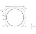
- FIG. 2A is a plan view showing an external example of the light source device according to the embodiment.
- FIG. 2B is a side view showing an external example of the light source device according to the embodiment.
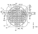
- FIG. 3A is a perspective view showing a configuration example of the light source device according to the embodiment.
- FIG. 3B is an enlarged view of a cross section taken along the line III-III of FIG. 3A.
- FIG. 4 is a partially enlarged view of the region B in FIG. 3B.
- FIG. 5 is a diagram showing an example of LED configuration.
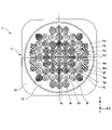
- FIG. 6 is a diagram showing an arrangement example of various light source units.
- FIG. 1 is a diagram showing an example of lighting by the light source device according to the embodiment.
- FIG. 2A is a plan view showing an external example of the light source device according to the embodiment.
- FIG. 2B is a side view showing an external example of the light source device according
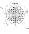
- FIG. 7 is a diagram showing an example of the orientation of each optical axis of the plurality of light source units.
- FIG. 8 is a diagram showing an example of the relationship between the central axis of the arrangement region and the direction of the optical axis of the light source unit.
- FIG. 9 is a diagram of an arrangement example in the irradiated area of the irradiation light by each light source unit.
- FIG. 10A is a diagram showing a first example of arrangement of a plurality of light source units according to a modified example.
- FIG. 10B is a diagram showing a second example of the arrangement of the plurality of light source units according to the modified example.
- FIG. 10C is a diagram showing a third example of the arrangement of the plurality of light source units according to the modified example.
- FIG. 10A is a diagram showing a first example of arrangement of a plurality of light source units according to a modified example.
- FIG. 10B is a diagram showing a second example of the arrangement of the pluralit
- FIG. 10D is a diagram showing a fourth example of arrangement of a plurality of light source units according to a modified example.
- FIG. 10E is a diagram showing a fifth example of arrangement of a plurality of light source units according to a modified example.
- FIG. 11 is a diagram comparing the light source device according to the embodiment and the light source device according to the reference example.
- FIG. 12 is a diagram illustrating the uniformity of illuminance.
- FIG. 13A is a diagram of the illuminance distribution of the irradiation light by the light source device according to the embodiment.
- FIG. 13B is a diagram of the illuminance distribution of the irradiation light by the light source device according to the reference example.
- the embodiments shown below exemplify a light source device for embodying the technical idea of the present invention, and the present invention is not limited to the embodiments shown below.
- the dimensions, materials, shapes, relative arrangements, etc. of the components described below are not intended to limit the scope of the present invention to the specific description, but are intended to be exemplified. It is a thing.
- the size and positional relationship of the members shown in the drawings may be exaggerated in order to clarify the explanation.
- the direction may be indicated by the X-axis, the Y-axis, and the Z-axis. It indicates a predetermined direction, the Y direction along the Y axis indicates a direction orthogonal to the X direction in the arrangement plane, and the Z direction along the Z axis indicates a direction orthogonal to the arrangement plane.
- the direction in which the arrow points in the X direction is referred to as the + X direction, the opposite direction in the + X direction is referred to as the -X direction, the direction in which the arrow points in the Y direction is referred to as the + Y direction, and the opposite direction in the + Y direction is referred to as the -Y direction.
- the direction in which the arrow points in the Z direction is referred to as the + Z direction
- the direction opposite to the + Z direction is referred to as the ⁇ Z direction.
- the plurality of light source units irradiate light on the + Z direction side as an example. However, this does not limit the orientation when the light source device is used, and the orientation of the light source device is arbitrary.
- FIG. 1 is a diagram illustrating an example of lighting by the light source device 1.
- the smartphone 100 has a back panel 101 and a light source device 1.
- the back panel 101 constitutes a part of the housing of the smartphone 100, and is a plate-shaped member provided on the side opposite to the front portion where the operation portion of the smartphone 100 such as a touch panel is provided.
- a substantially circular through hole 102 is formed in the back panel 101.
- the light source device 1 is provided in the housing of the smartphone 100 so as to be able to irradiate light through the above-mentioned through hole 102.
- the light source device 1 is, for example, a flashlight used for a portable lighting device such as a flashlight, or a lighting device that emits a flash (flash) for photography.
- the light source device 1 irradiates the irradiation light 2 in the direction (+ Z direction) along the central axis of the through hole 102, and illuminates an object such as a person or an object existing in the irradiation direction. Further, as shown in FIG. 1, the light source device 1 is configured to be able to illuminate the irradiated area 3 which is a rectangular area.
- the irradiated area 3 is, for example, a rectangular area in which the ratio of the length in the longitudinal direction along the X direction to the length in the lateral direction along the Y direction is 4: 3.
- the irradiated area 3 is not limited to the surface area of a flat object such as a wall surface or a screen, but may be a surface area of an object having irregularities, or a spatial area in which the object does not exist. It may be.
- FIGS. 2A and 2B are views showing an example of the appearance of the light source device 1.
- 2A is a plan view and FIG. 2B is a side view.
- the light source device 1 has a substrate 10 and a light guide array unit 11 provided on a surface of the substrate 10 on the + Z direction side.
- the substrate 10 is a substantially square plate-shaped member, and is a substrate provided with wiring on which light emitting elements such as LEDs (Light Emitting Diodes) and LDs (Laser Diodes) and various electric elements can be mounted.
- a substrate of various materials such as a metal substrate, a paper phenol substrate, a paper epoxy substrate, or a glass epoxy substrate can be applied to the substrate 10.
- the light guide array unit 11 is a member in which a plurality of light guide members arranged in an array are integrally formed. As shown in FIG. 2A, the light guide array unit 11 has a circular planar arrangement region 12 formed in a substantially circular shape in a plan view and a peripheral region 13 in which a plan view is formed in a substantially square shape and surrounds the arrangement region 12. Is configured to include.
- the circular plane of the arrangement region 12 is a plane parallel to the above-mentioned arrangement plane. Further, the outer shape of the peripheral region 13 substantially matches the outer shape of the substrate 10. Therefore, in FIG. 2A, the substrate 10 is hidden by the light guide array unit 11 and is not visible.
- the + Z direction side in the arrangement region 12 of the light guide array unit 11 is formed in a planar shape (in other words, a substantially flat surface). Further, a plurality of light guide members are formed on the ⁇ Z direction side of the arrangement region 12 of the light guide array unit 11. The surface of the peripheral region 13 on the ⁇ Z direction side is in contact with the surface of the substrate 10 on the + Z direction side. The light guide array portion 11 is fixed to the surface of the substrate 10 on the + Z direction side by adhering the contacting surfaces with an adhesive or the like.
- the light guide array unit 11 is shown as if it is an opaque member, but the light guide array unit 11 according to the present embodiment is shown.
- At least the arrangement area 12 is a transparent member.
- "transparency” means having transparency to at least one of visible light and invisible light.
- the light guide array unit 11 has transparency to visible light.
- the light guide array unit 11 can be manufactured by processing a polycarbonate resin material by injection molding. However, the present invention is not limited to this, and the light guide array unit 11 can be manufactured from various resin materials such as acrylic resin, glass materials, and the like. Other processing methods such as cutting may be applied. Further, the light guide array unit 11 may be made of colored resin, or an optical bandpass filter may be provided to limit the wavelength of light transmitted through the light guide array unit 11.
- the length L of the light source device 1 is preferably 30 mm or more and 40 mm or less, and the diameter D of the arrangement region 12 is preferably 27 mm or more and 37 mm or less.
- the height (length along the Z-axis direction) h of the light guide array unit 11 is preferably 2 mm or more and 3 mm or less.
- FIGS. 3A and 3B are diagrams illustrating an example of the configuration of the light source device 1.
- 3A is a perspective view
- FIG. 3B is an enlarged view of a cross section taken along the line III-III of FIG. 3A.
- FIG. 3A sees through the surface of the arrangement region 12 on the + Z direction side of the light guide array unit 11, and shows the configuration of the arrangement region 12 on the ⁇ Z direction side.
- the TIR lens 41 is an example of a light guide member including a total reflection surface 411 that totally reflects light. Specifically, it has a total reflection surface 411 that totally reflects light inside the TIR lens 41.
- the light source device 1 includes a total of 63 TIR lenses 41.
- the TIR lens 41 is a general term for a plurality of TIR lenses such as the TIR lenses 41a, 41b, 41c and 41d in FIG. 3B. Further, the total reflection surface 411 is a general term for a plurality of total reflection surfaces such as the total reflection surfaces 411a, 411b, 411c and 411d in FIG. 3B.
- the TIR lens 41 is a component formed on the back side (-Z direction side) of the arrangement region 12, but is shown by a solid line in FIG. 3A for the convenience of easy viewing. This point is the same in the figure after which the TIR lens 41 is displayed by seeing through the arrangement region 12.
- the total reflection surface 411 is a surface formed in a tapered shape that tapers toward the ⁇ Z direction.
- the shape of the total reflection surface 411 is not limited to the tapered shape, and may be a bowl-shaped shape including a curved surface. Further, it does not necessarily have to be formed axially symmetric with respect to an axis parallel to the Z axis.
- the TIR lens may be formed substantially axisymmetric with respect to the center line of the TIR lens.
- the center line of the TIR lens means a line passing through the substantially center of the TIR lens in a plane parallel to the array plane.
- the center line 410 shown in FIG. 3A represents the center line of the TIR lens 41.
- the adjacent TIR lenses 41 among the plurality of TIR lenses 41 are connected to each other on the exit surface 111 side that emits light.
- the TIR lenses 41a, 41b, 41c and 41d are connected on the exit surface 111 side.
- the plurality of TIR lenses 41 include those having different shapes.
- the TIR lens 41a has a shape substantially axisymmetric with respect to the central axis 41ac of the TIR lens 41a.
- the TIR lens 41a includes a total reflection surface 411a and a truncated cone surface 412a which is a surface formed in a substantially cone shape.
- Each of the total reflection surface 411a and the conical base surface 412a is formed substantially axially symmetric with respect to the central axis 41ac of the TIR lens 41a.
- the central axis of the TIR lens is an axis that passes through the substantially center of the TIR lens and is substantially parallel to the Z axis, and refers to the midpoint of the maximum diameter of the TIR lens in plan view.
- the TIR lens 41b is not formed in a shape that is axisymmetric with respect to the central axis 41bc of the TIR lens 41b.
- the TIR lens 41b includes a total reflection surface 411b and a conical base surface 412b.
- Each of the total reflection surface 411b and the conical base surface 412b is formed substantially axisymmetric with respect to the center line of the TIR lens 41b (see the center line 410 described above), and is not axially symmetric.
- each of the total reflection surface 411c and the conical base surface 412c of the TIR lens 41c is formed substantially axisymmetric with respect to the center line of the TIR lens 41c (see the center line 410 described above), and is the center of the TIR lens 41c. It is not axisymmetric with respect to the axis 41cc.
- each of the total reflection surface 411d and the conical base surface 412d of the TIR lens 41d is formed substantially line-symmetrically with respect to the center line of the TIR lens 41d (see the center line 410 described above), and the central axis 41dc of the TIR lens 41d is formed. It is not axisymmetric with respect to.
- the conical base surface 412 which will be described later, is a general term for the conical base surfaces 412a, 412b, 412c, and 412d.
- the TIR lens 41a is an example of the first light guide member
- the TIR lens 41b is an example of the second light guide member.
- the shape of the TIR lens 41a and the shape of the TIR lens 41b are different.
- the TIR lens 41b is exemplified as the second light guide member, any of the plurality of TIR lenses arranged outside the center in the arrangement region 12 corresponds to the second light guide member. That is, all the TIR lenses other than the TIR lens 41a among the plurality of TIR lenses 41 correspond to the second light guide member.
- the LED 42 is provided on the substrate 10 at a position facing each of the plurality of TIR lenses 41 so as to have a one-to-one correspondence with the TIR lens 41.
- the LED 42a is provided facing the TIR lens 41a, and the LED 42b is provided facing the TIR lens 41b. Further, the LED 42c is provided facing the TIR lens 41c, and the LED 42d is provided facing the TIR lens 41d.
- the LED 42 is an example of a light emitting element. Further, LED 42 is a general term for a plurality of LEDs such as LEDs 42a, 42b, 42c and 42d.
- the light source device 1 includes a total of 63 LEDs 42 corresponding to a total of 63 TIR lenses 41.
- Each of the plurality of LEDs 42 is electrically connected to the drive circuit 20 via the substrate 10 and emits light in response to the drive voltage applied from the drive circuit 20. Further, each of the plurality of LEDs 42 is configured to be able to independently control the switching between light emission and non-light emission, the light intensity of light emission, and the like in response to the control signal input to the drive circuit 20.
- the LED 42 emits, for example, white light.
- the light emitted by the LED 42 is not limited to white light, and may be monochromatic light, and various types of white light such as light bulb color, neutral white, and daylight color can be selected.
- the light emitted by the LED 42 is guided by the TIR lens 41 and emitted through the emission surface 111.
- the light source device 1 can illuminate the irradiated area with this emitted light.
- each of the plurality of TIR lenses 41 included in the light guide array unit 11 can guide the light incident from the LED 42 and then emit the light through the emission surface 111 to irradiate the irradiated area.
- the set of the TIR lens 41a and the LED 42a constitutes the light source unit 4a
- the set of the TIR lens 41b and the LED 42b constitutes the light source unit 4b
- the set of the TIR lens 41c and the LED 42c constitutes the light source unit 4c
- the set of the TIR lens 41d and the LED 42d constitutes the light source unit 4d.
- the light source unit 4 is a general term for a plurality of light source units such as the light source units 4a, 4b, 4c, and 4d.
- the light source device 1 includes a total of 63 light source units 4 by a pair of a TIR lens 41 and an LED 42.
- TIR lenses 41 and LEDs 42 need to be provided in a one-to-one correspondence, and either one of some TIR lenses 41 or LED 42 may be provided independently instead of a set.
- the positional relationship between the TIR lens 41 and the LED 42 in the light source unit 4 differs depending on the position of the light source unit 4 in the arrangement area 12. Specifically, the distance between the center of the LED 42 and the central axis of the TIR lens 41 increases as the light source unit 4 is arranged farther from the central axis 14 of the arrangement region 12. That is, the distance between the center of the LED 42 and the central axes 41ac, 41bc, 41cc, and 42dc of the TIR lens 41 increases in the order of the light source portions 4a, 4b, 4c, and 4d.
- the central axis 14 of the arrangement area 12 is an axis that penetrates the substantially center of the arrangement area 12 and is an axis that is substantially orthogonal to the arrangement area 12 (an axis that is substantially parallel to the Z axis).
- the center of the LED 42a substantially coincides with the central axis 41ac of the TIR lens 41a.
- the center of the LED 42b is displaced in the + X direction with respect to the central axis 41bc of the TIR lens 41b.
- the center of the LED 42c is further displaced in the + X direction with respect to the central axis 41cc of the TIR lens 41c, and the deviation is larger than the displacement of the LED 42b with respect to the central axis 41bc of the TIR lens 41b.
- the center of the LED 42d is further displaced in the + X direction with respect to the central axis 41dc of the TIR lens 41d, and the deviation is larger than the displacement of the LED 42c with respect to the central axis 41cc of the TIR lens 41c.
- the light source portions 4n arranged in the triangular lattice region 5 indicated by the square of the two-dot chain line are arranged in a triangular lattice pattern.
- the light source portions 4a, 4b, 4c and 4d are arranged in a rectangular grid pattern in the arrangement region 12.
- the light source unit 4d is also arranged in the triangular lattice region 5, and is also one of the light source units arranged in a triangular lattice pattern.
- the TIR lenses 41n included in the light source unit 4n are arranged in a triangular lattice pattern. Further, in the arrangement region 12, the TIR lenses 41a, 41b, 41c and 41d are arranged in a rectangular grid pattern. Here, the TIR lens 41d is also arranged in the triangular lattice region 5 and is also one of the TIR lenses arranged in a triangular lattice pattern.
- the light source device 1 when the light source device 1 is viewed in a plan view, a certain light source unit is used as a first light source unit, and a light source unit adjacent to the first light source unit along the first direction is used as a second light source unit. .. Further, the light source unit adjacent to the first light source unit along the second direction orthogonal to the first direction is referred to as a third light source unit. Further, a light source unit adjacent to the third light source unit along the first direction and adjacent to the second light source unit along the second direction is referred to as a fourth light source unit. In FIGS. 3A and 3B, the Y direction corresponds to the first direction and the X direction corresponds to the second direction. In addition, "adjacent" means that they are adjacent to each other.
- the triangular grid arrangement means that the center position between the first light source unit and the second light source unit along the first direction and the center of the third light source unit are along the second direction. It means that it is placed in.
- the center of the first light source portion and the center of the third light source portion along the second direction are arranged so as to be short.
- the first to third light source portions can be arranged at a higher density.
- the triangles in the triangular lattice arrangement include various triangles such as equilateral triangles and isosceles triangles.
- an equilateral triangle or an isosceles triangle whose base is a line connecting the center of the first light source portion and the center of the second light source portion is that the first to third light source portions are arranged at a higher density. preferable.
- the center of the first light source unit and the center of the third light source unit are arranged along the second direction, and the center of the second light source unit and the fourth light source unit are arranged. It means that the center of the light source unit is arranged along the second direction. It should be noted that the rectangle in the rectangular grid-like array includes at least one of the square and the rectangle.
- the light source unit 4p 1 corresponds to the first light source unit. Since the light source unit 4p 2 is adjacent to the light source unit 4p 1 along the Y direction, it corresponds to the second light source unit. Since the light source unit 4q is adjacent to the light source unit 4p1 along the X direction, it corresponds to the third light source unit.
- the center position M between the center 4pc 1 of the light source unit 4p 1 and the center 4pc 2 of the light source unit 4p 2 and the center 4qc of the light source unit 4q are arranged along the X direction. Therefore, the light source unit 4p 1 and the light source unit 4p 2 and the light source unit 4q are arranged in a triangular lattice pattern.
- the light source unit 4s corresponds to the first light source unit. Since the light source unit 4u is adjacent to the light source unit 4s along the Y direction, it corresponds to the second light source unit. Since the light source unit 4t is adjacent to the light source unit 4s along the X direction, it corresponds to the third light source unit. Since the light source unit 4v is adjacent to the light source unit 4u along the X direction and adjacent to the light source unit 4t along the Y direction, it corresponds to the fourth light source unit.
- the center 4sc of the light source unit 4s and the center 4tc of the light source unit 4t are arranged along the X direction, and the center 4uc of the light source unit 4u and the center 4vic of the light source unit 4v are arranged along the X direction. Therefore, the light source units 4s, 4t, 4u, and 4v are arranged in a rectangular grid pattern.
- the center of the light source unit is located on the central axis of the light guide member included in the light source unit (in this embodiment, on the central axis of the TIR lens). Further, the center position of the light source unit does not have to be strictly the center position of the light source unit, and may be a substantially center position of the light source unit.
- abbreviation means that a difference generally recognized as an error is allowed. The difference that is generally recognized as an error is, for example, a variation of 1/5 or less of the design value.
- the central position between the first light source unit and the second light source unit does not have to be strictly the central position, but may be a substantially central position. Further, the arrangement along the center position and the center, or the arrangement along the second direction between the centers does not require the arrangement strictly parallel to the second direction, and may be arranged along approximately the second direction.
- the center of the first light source unit and the third light source unit are used.
- the distance along the Y direction between the center of the unit and the center of the second light source unit is D / 5 or less
- the distance between the center of the second light source unit and the center of the fourth light source unit is D / 5 or less. If so, the first to fourth light source portions are arranged in a rectangular grid pattern.
- the distance along the Y direction between the center position M between the center of the first light source unit and the center of the second light source unit and the center of the third light source unit is D / 5 or less.
- the first to third light source portions are arranged in a triangular lattice pattern.
- the shortest distance between the center of the first light source unit and the center of the third light source unit, and the shortest distance between the center of the second light source unit and the center of the third light source unit are D, respectively. It is preferably / 2 or more and 2 ⁇ D or less.
- the positional relationship when the second light source unit is arranged on the ⁇ Y direction side of the first light source unit and the third light source unit is arranged on the + X direction side of the first light source unit has been described as an example.
- the positional relationship of the first to fourth light source units is not limited to this. For example, the same applies even if the second light source unit is arranged on the + Y direction side of the first light source unit and the third light source unit is arranged on the ⁇ X direction side of the first light source unit. ..
- the light source unit 4n is an example of the light source unit arranged on the peripheral edge portion in the arrangement region 12. Further, the center line 410n of the TIR lens 41n in the light source unit 4n is arranged so as to be tilted by a predetermined angle with respect to the rectangular grid-like arrangement direction (for example, the X direction) of the light source units 4a, 4b, 4c, 4d and the like.
- the predetermined angle is, for example, 45 degrees.
- the TIR lens included in the light source portion arranged on the peripheral portion of the arrangement region 12 has a substantially elliptical top view, but even in this case, the center line 410n is provided by a predetermined angle with respect to the arrangement direction. By tilting, it becomes possible to arrange the TIR lens having a substantially elliptical shape at a higher density.
- Each of the light source units 4a, 4b, 4c and 4d is an example of the light source unit arranged in the central portion of the arrangement region 12.
- FIG. 4 is a partially enlarged view of a region B surrounded by a broken line square in FIG. 3B, and is a diagram illustrating an example of a state of light guidance by the TIR lens 41 of light emitted by the LED 42.
- the divergent light emitted from the LED 42a toward the + Z direction is incident on the inside of the TIR lens 41a through the conical base surface 412a.
- the incident light 413a (indicated by a broken arrow) incident through the slope portion of the conical base surface 412a is totally reflected by the total reflection surface 411a and then emitted through the emission surface 111.
- the light emitted from the exit surface 111 after being totally reflected by the total reflection surface 411a is referred to as the first central light of the TIR lens 41a.
- the incident light 414a incident on the inside of the TIR lens 41a through the upper bottom portion of the conical base surface 412a reaches the emission surface 111 without reaching the total reflection surface 411a, and is emitted through the emission surface 111.
- the light emitted directly from the exit surface 111 without passing through the total reflection surface 411a is referred to as the second central light of the TIR lens 41a.
- the light intensity or spread angle of the first central light and the second central light can be set to a desired state.
- the light guiding by the TIR lens of the light emitted by the LED is described by taking the TIR lens 41a as an example, but the light guiding function is the same in other TIR lenses.
- FIG. 5 is a diagram illustrating an example of the configuration of the LED 42.
- FIG. 5 shows one of a plurality of LEDs 42 as a representative example.
- the plurality of LEDs 42 all have the same configuration, but are not limited to this, and may include LEDs having different configurations as a part thereof.
- the LED 42 has a block-like shape with a substantially square view in a plan view.
- a light emitting unit 421 is provided in the center of the LED 42.
- the LED 41 can emit white light from the light emitting unit 421.
- the LED 42 is located between the two lower ends of the conical base surface 412 of the TIR lens 41 in the X direction or the Y direction, and the length S along the X direction and the Y direction of the LED 42 is 480 ⁇ m or more. It is preferably 620 ⁇ m or less. Further, the length C of the light emitting unit 421 along each of the X direction and the Y direction is preferably 280 ⁇ m or more and 420 ⁇ m or less.
- the LED 42 is arranged so as to be substantially axisymmetric with respect to the center line of the TIR lens for each light source unit. The dimensions of the LED 42 and the dimensions of the light emitting unit 421 can be adjusted as appropriate.
- the LED 42 includes at least a light emitting element, a wavelength conversion member arranged on the light emitting element and containing a wavelength conversion substance, and a light reflecting covering member that at least covers the side surface of the light emitting element and the side surface of the wavelength conversion member.
- the light emitting unit 421 includes a light emitting element and a wavelength conversion member
- the outer peripheral 422 of the light emitting unit 421 includes a covering member.
- the light emitting element is a semiconductor element that emits light by itself by applying a voltage.
- the light emitting device includes at least a semiconductor laminate and has electrodes having different polarities, for example, a p-side electrode and an n-side electrode.
- As the material of the semiconductor it is preferable to use a nitride semiconductor which is a material capable of emitting short wavelength light capable of efficiently exciting a wavelength conversion substance contained in the wavelength conversion member.
- Nitride semiconductors are mainly represented by the general formula In x Al y Ga 1-xy N (0 ⁇ x, 0 ⁇ y, x + y ⁇ 1).
- the emission peak wavelength of the light emitting element is preferably 400 nm or more and 530 nm or less, more preferably 420 nm or more and 490 nm or less, and more preferably 450 nm or more and 475 nm or less from the viewpoint of luminous efficiency, excitation of the wavelength converting substance and the color mixing relationship with the emission thereof. More preferable.
- the semiconductor material an InAlGaAs-based semiconductor, an InAlGaP-based semiconductor, or the like can also be used.
- the wavelength conversion member is a member containing a wavelength conversion substance using a resin such as silicone as a base material.
- the wavelength conversion substance is a member that absorbs at least a part of the primary light emitted by the light emitting element and emits secondary light having a wavelength different from that of the primary light.
- Examples of the wavelength conversion substance include yttrium aluminum garnet phosphor (for example, Y 3 (Al, Ga) 5 O 12 : Ce) and terbium aluminum garnet phosphor (for example, Lu 3 (Al, Ga)).
- Phosphoric elements excluding Ce) Phosphoric elements excluding Ce
- nitride-based phosphors such as CASN-based phosphors (eg, CaAlSiN 3 : Eu) or SCASN-based phosphors (eg, (Sr, Ca) AlSiN 3 : Eu), KSF-based fluorescence.
- a fluoride-based phosphor such as a body (for example, K 2 SiF 6 : Mn) or an MGF-based phosphor (for example, 3.5 MgO / 0.5 MgF 2 : GeO 2 : Mn), a CCA-based phosphor (for example, (Ca) , Sr) 10 (PO 4 ) 6 Cl 2 : Eu), or a quantum dot phosphor or the like can be used.
- a body for example, K 2 SiF 6 : Mn
- MGF-based phosphor for example, 3.5 MgO / 0.5 MgF 2 : GeO 2 : Mn
- a CCA-based phosphor for example, (Ca) , Sr) 10 (PO 4 ) 6 Cl 2 : Eu
- a quantum dot phosphor or the like can be used.
- the wavelength conversion substance one of these fluorescent substances can be used alone, or two or more of these fluorescent substances can be used in combination.
- the covering member preferably has light reflectivity in order to take out the light from the light emitting element to the upper surface side (+ Z direction), and the width ((length S-length C) of the outer circumference 422 of the light emitting portion 421 in a plan view. ) / 2) is preferably 100 ⁇ m or more.
- the light reflectance with respect to the emission peak wavelength of the light emitting element is preferably 70% or more, more preferably 80% or more, still more preferably 90% or more.
- the covering member is preferably white, and the base material of the covering member preferably contains a white pigment such as titanium oxide or magnesium oxide.
- the base material of the covering member 40 include resins such as silicone, epoxy, phenol, polycarbonate, and acrylic, or modified resins thereof.
- the type of the light source unit refers to a group of light source units having the same properties or forms.
- the light source unit is classified according to the position where the light source unit is arranged. More specifically, the light source units having the same distance from the central axis 14 of the arrangement region 12 are the same type of light source unit.
- FIG. 6 is a diagram illustrating an example of arrangement of various light source units 4. Similar to FIG. 3A, FIG. 6 sees through the surface of the arrangement region 12 on the + Z direction side of the light guide array unit 11 and shows the configuration of the arrangement region 12 on the ⁇ Z direction side. In this embodiment, a total of 63 light source units 4 are classified into 14 types of light source units 4a to 4n. In FIG. 6, the light source units 4a to 4n are classified and displayed according to the type of hatching.
- one light source unit arranged at the center of the 63 light source units 4 corresponds to the light source unit 4a.
- the four light source units arranged adjacent to each of the + X direction side, the ⁇ X direction side, the + Y direction side, and the ⁇ Y direction side of the light source unit 4a correspond to the light source unit 4b, respectively.
- the four light source units classified into the light source unit 4b are arranged at positions where the distances from the central axis 14 of the arrangement region 12 are equal.
- the types of the light source units 4a to 4n are different depending on the positions in which they are arranged. Further, since the number of light source units that can be arranged differs depending on the position, the number of light source units also differs depending on the type. Table 1 is a list showing the number of light source units 4a to 4n for each type.
- FIG. 7 is a diagram illustrating an example of the orientation of each optical axis of the plurality of light source units 4.
- FIG. 7 sees through the surface of the arrangement region 12 on the + Z direction side of the light guide array unit 11, and shows the light source unit including the TIR lens and the LED on the ⁇ Z direction side of the arrangement region 12.
- the optical axis in the light source unit means the central axis of the luminous flux emitted by the light source unit.
- the luminous flux emitted by the light source unit is, in other words, the irradiation light emitted by the light source unit, and is divergent light, focused light, parallel light, or the like.
- the direction of the optical axis is determined according to the shape of the TIR lens included in the light source unit, the positional relationship between the TIR lens and the LED, and the like.
- the shape of the TIR lens is, for example, a shape corresponding to the direction of the center line of the TIR lens.
- the light source unit can irradiate light in the direction along the direction of the optical axis.
- the light source unit 4c has a TIR lens 41c and an LED 42c.
- the optical axis 43c indicated by the arrow indicates the optical axis of the light source unit 4c, and the arrow of the optical axis 43c indicates the direction of the optical axis.
- the optical axis 43c is directed toward the central axis 14 of the arrangement region 12.
- the four light source units 4m and the four light source units 4n have their optical axes not directed to the central axis 14 of the arrangement region 12, and the other parts.
- the 55 light source units 4 of the above are configured so that the optical axis of the light source unit 4 faces the central axis 14 of the arrangement region 12.
- the plurality of light source units 4 has an optical axis 43 in a direction of irradiating toward the central axis 14 of the arrangement region 12.
- the direction of irradiating toward the central axis 14 of the arrangement region 12 means a direction intended to intersect the central axis of the arrangement region 12.
- the optical axis 43 is a general term for optical axes possessed by a plurality of light source units such as the optical axes 43c, 43m, and 43n.
- FIG. 8 is a diagram illustrating an example of the relationship between the central axis 14 of the arrangement region 12 and the orientation of the optical axis 43 in the light source unit 4 in more detail.
- the view of FIG. 8 is the same as that of FIG. 7, but in FIG. 8, one of the four light source units 4c, one of the four light source units 4m, and the four light sources of the plurality of light source units 4 One of the parts 4n is displayed, and the display of the other light source parts is omitted for the convenience of easy viewing.
- the arrow indicating the optical axis is extended and displayed in the direction indicating the direction of the optical axis.
- the optical axis 43c intersects the central axis 14 of the arrangement region 12.
- the light source unit 4c arranged in the central portion of the arrangement region 12 has an optical axis 43c in the direction of irradiating toward the central axis 14 of the arrangement region 12.
- the light source device 1 is manufactured aiming at the intersection of the optical axis 43c and the central axis 14 of the arrangement region 12, but strictly speaking, due to a manufacturing error, the optical axis 43c and the center of the arrangement region 12 are centered.
- the shaft 14 does not intersect and both are in a twisted position.
- the twisted position means the positional relationship between two straight lines that are not parallel and do not intersect.
- the operation and effect (described later) of the light source device 1 according to the present embodiment can be obtained even if there is such a slight twist that is generally recognized as a manufacturing error. Therefore, the “intersection of the optical axis 43c and the central axis 14 of the arrangement region 12” in the present embodiment includes such a twist that is generally recognized as a manufacturing error.
- the light source unit 4c is shown as an example, but the same applies to the light source unit 4m and other light source units other than the light source unit 4n among the plurality of light source units 4.
- each of the optical axis 43m and the optical axis 43n does not intersect the central axis 14 of the arrangement region 12.
- the light source unit 4m arranged on the peripheral edge of the arrangement region 12 has an optical axis 43m in the direction of irradiation at a twisted position with respect to the central axis 14 of the arrangement region 12.
- the light source unit 4n arranged on the peripheral edge of the arrangement region 12 has an optical axis 43n in a direction of irradiation at a twisted position with respect to the central axis 14 of the arrangement region 12. That is, at least a part of the light source portion arranged on the peripheral edge portion of the arrangement region 12 has an optical axis 43 in a direction of irradiation at a twisted position with respect to the central axis 14 of the arrangement region 12.
- the light source unit 4c which is a part of the light source unit 4 is directed toward the central axis 14 which is an axis orthogonal to the plane of the arrangement region 12. It has an optical axis 43c.
- the light source unit 4m which is a part of the light source unit 4 has an optical axis 43m in a twisted position with respect to the central axis 14 which is an axis orthogonal to the plane of the arrangement region 12.
- the light source unit 4n which is a part of the light source unit 4, has an optical axis 43n in a twisted position with respect to the central axis 14 which is an axis orthogonal to the plane of the arrangement region 12.
- the light emitted by some of the TIR lenses 41 among the plurality of TIR lenses 41 included in the plurality of light source units 4 in a one-to-one correspondence is on the plane of the arrangement region 12. It has an optical axis in the direction of irradiation toward the central axis 14, which is an orthogonal axis. Further, among the plurality of TIR lenses 41, the light emitted by some of the TIR lenses 41 has an optical axis in a direction of irradiation at a twisted position with respect to the central axis 14 which is an axis orthogonal to the plane of the arrangement region 12. .. In FIGS. 7 and 8, the optical axis of the light emitted by the TIR lens 41 coincides with the optical axis 43 of the light source unit 4.
- FIG. 9 is a diagram illustrating an example of an arrangement of the irradiation light emitted by each light source unit in the irradiated area.
- the light source device 1 irradiates the irradiated area 3 with the irradiation light 2.
- the diagram of the matrix displayed in the irradiated area 3 in FIG. 9 represents a partial area illuminated by the irradiation light from each of the plurality of light source units.
- the types of hatching in each subregion are displayed differently according to the type of each light source unit.
- the irradiated region 3 is formed by aggregating a plurality of partial regions.
- FIG. 9 shows a partial region illuminated by the irradiation light of each of the plurality of light source units 4 in a one-to-one relationship, which is a portion where the light emitted from the light source unit 4 actually corresponds.
- each light source unit 4 is an area targeted by the light source unit 4 for irradiation. Therefore, in practice, the light emitted from one light source unit 4 may illuminate at least a part of an adjacent partial region (or a nearby partial region).
- the light source units other than the light source units 4m and 4n have an optical axis 43 in the direction of irradiation toward the central axis 14 of the arrangement region 12. Therefore, the irradiation light from each light source unit other than the light source unit 4m and 4n illuminates the partial region 31 at a position symmetrical with respect to the central axis 14 of the arrangement region 12 in the irradiated region 3.
- the irradiation light 2j 1 by the light source unit 4j 1 illuminates the partial region 31j 1 located at a position symmetrical to the light source unit 4j 1 with the central axis 14 of the arrangement region 12 interposed therebetween. Further, the irradiation light 2j 2 by the light source unit 4j 2 illuminates the partial region 31j 2 located at a position symmetrical to the light source unit 4j 2 with the central axis 14 of the arrangement region 12 interposed therebetween.
- the partial region 31 is a general term for a plurality of partial regions such as the partial regions 31j 1 and 31j 2 .
- the plurality of light source units 4 are arranged in the circular planar arrangement area 12 and as many light source units 4 as possible are arranged in the arrangement area 12, the plurality of light source units 4 are arranged. It is arranged so that the entire outer shape becomes a circular shape according to the outer shape of the arrangement area 12.
- the irradiated area 3 in which the irradiation light from the plurality of light source units 4 is arranged has the arrangement of the plurality of light source units 4. It becomes a circular area according to.
- the light source portions 4m and 4n of the plurality of light source portions 4 irradiate the central axis 14 of the arrangement region 12 with light at a twisted position, so that the irradiated region 3 is rectangular. It is designed to be a region of shape.
- the light source unit 4m 1 illuminates the partial region 31m 1 by irradiating the central axis 14 of the arrangement region 12 with light at a twisted position, and the light source unit 4m 2 illuminates the central axis 14 of the arrangement region 12.
- the partial region 31m 2 is illuminated by irradiating the light at the twisted position.
- the light source unit 4n 1 illuminates the partial region 31n 1 by irradiating the central axis 14 of the arrangement region 12 with light at a twisted position
- the light source unit 4n 2 illuminates the central axis 14 of the arrangement region 12.
- the partial region 31n 2 is illuminated by irradiating light at the twisted position. By doing so, the irradiated area 3 becomes a rectangular area.
- each of the plurality of light source units is arranged in a matrix in the rectangular illuminated area 3. Since the plurality of light source units 4 are arranged in a combination of a rectangular grid shape and a triangular grid shape in the circular planar arrangement region 12, at least a part of the plurality of light source units 4 is irradiated in the irradiated area 3. It is arranged in a state different from the arrangement of light.
- the light emitted by each of the TIR lenses included in the plurality of light source units is arranged in a matrix in the rectangular irradiated area 3. Since the TIR lens included in the plurality of light source units 4 is arranged in a combination of a rectangular grid shape and a triangular grid shape in the circular planar arrangement region 12, at least a part of the TIR lens included in the plurality of light source units 4 Are arranged in a state different from the arrangement of the irradiation light in the irradiated area 3.
- each of the plurality of partial regions 31 is a rectangular region, but the region is not limited to this, and may be a circular or elliptical region.
- the light emitted by each of the plurality of light source units may be arranged in a matrix in the irradiated area 3 in a state where the light emitted by the adjacent light source units partially overlaps with each other.
- the light emitted by each of the plurality of light source units may be arranged in a matrix in the irradiated area 3 with a gap between the lights emitted by the adjacent light source units.
- a plurality of light source portions included in the light source device 1 are arranged in a combination of at least a rectangular grid shape and a triangular grid shape in a circular planar arrangement region.
- 55 of the 63 light source units 4 are arranged in a rectangular grid pattern (that is, in a matrix), and the remaining 8 light source units 4 are arranged in a triangular grid pattern at the peripheral portion of the arrangement region 12.
- the light emitted by each of the plurality of light source units is arranged in a matrix in the irradiated area. This makes it easy to understand which light source unit illuminates which partial region, that is, the irradiation pattern, for example, when a plurality of light source units are independently controlled to irradiate light in various patterns.
- the light source device may become large.
- at least a rectangular grid shape and a triangular grid shape are arranged in combination.
- the light emitted by each of the plurality of light source units 4 is arranged in a matrix in the irradiated area 3, and at least a part of the plurality of light source units 4 is arranged with the irradiation light in the irradiated area 3. Arrange in different states. This makes it easier to understand the irradiation pattern in the irradiated area 3, and the plurality of light source units 4 and the TIR lens 41 can be housed in the circular planar arrangement area 12.
- the irradiated area is a circular area, it may not be possible to efficiently illuminate the entire information included in the rectangular area of the information display means. For example, there is a lot of wasted light illuminating areas where there is no information.
- the light source device 1 and the light guide array unit 11 having a circular shape and a neat and beautiful appearance are provided, and in the information display means and the like.
- the rectangular area can be illuminated efficiently.
- At least a part of the plurality of light source units 4 has an optical axis in a direction of irradiating toward the central axis 14 of the arrangement region 12.
- a part of the irradiation light may be blocked (blocked) by a smartphone housing or the like existing around the arrangement area 12. be.
- vignetting increases.
- the light source unit 4 arranged in the central portion of the arrangement region 12 among the plurality of light source units 4 is arranged in a rectangular grid pattern, and is located on the peripheral portion of the arrangement region 12 among the plurality of light source units 4. At least a part of the light source unit 4 to be arranged is arranged in a triangular lattice pattern.
- the light source unit 4 By arranging the light source unit 4 in a rectangular grid pattern, it becomes easier to understand the irradiation pattern, and by arranging the light source unit 4 in a triangular grid pattern, the light source unit 4 can be accommodated in the circular planar arrangement region 12. can. As a result, the rectangular irradiated area 3 can be formed, and the rectangular area in the information display means or the like can be efficiently illuminated.
- the light source unit 4 arranged in the central portion has an optical axis in the direction of irradiating toward the central axis 14 of the arrangement region 12, and at least a part of the light source unit 4 arranged in the peripheral portion.
- the irradiated area 3 becomes a rectangular area. can do. Then, the rectangular area in the information display means or the like can be efficiently illuminated.
- the light guide member included in the plurality of light source units 4 includes a first light guide member including a total reflection surface that totally reflects light, and a second guide including a total reflection surface that totally reflects light.
- the shape of the first light guide member and the shape of the second light guide member are different from each other, including the optical member. Thereby, the irradiation direction of the irradiation light by the light source unit can be set in a desired direction according to the arrangement position.
- the plurality of light source units 4 are connected on the surface side where the adjacent light guide members emit light.
- a light guide member having a plurality of TIR lenses can be integrally formed, the work of assembling the plurality of light guide members and the like can be reduced, and the labor and time in manufacturing the light source device 1 can be reduced.
- each of the plurality of light source units 4 can independently irradiate light. This enables lighting in various patterns. Further, it is possible to freely switch the illumination position, the illumination direction, the illumination range, and the like without moving the light source device 1.
- FIG. 10A is a diagram illustrating a first example of arrangement of a plurality of light source units according to a modified example.
- the light source device 1a has a light guide array unit 11a.
- a plurality of light source units 4aa composed of the TIR lens 41aa included in the light guide array unit 11a and the LED 42 are arranged concentrically.
- the concentric arrangement means that the substantially center of each light source unit 4aa is arranged on a plurality of circles 103 having different radii around the central axis 14 of the arrangement area 12.
- the circle 103 shown by the alternate long and short dash line in FIG. 10A is shown for convenience of explaining the concentric arrangement, and is not a component included in the light source device 1a.
- the arrangement area 12 in the light guide array unit 11a has transparency to visible light
- a user such as a smartphone equipped with the light source device 1a can visually recognize the light source unit 4aa arranged in the arrangement area 12 from the outside.
- the regularity of arrangement in the entire plurality of light source units 4aa can be ensured, so that the appearance of the light source device 1a when visually recognized can be improved.
- FIGS. 10B and 10C are diagrams showing a number of light source units other than 63
- FIG. 10B is a second example of arrangement of a plurality of light source units
- FIG. 10C is a third of arrangement of a plurality of light source units. It is a figure which shows each example.
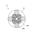
- the light source device 1b has four light source units 4Ab arranged in a rectangular grid pattern and four light source units 4Bb arranged in a triangular grid pattern (specifically, each triangle). It has four light source units 4Bb), which is one of the lattices, in the arrangement region 12.
- the light source unit 4Ab is a generic notation for the light source units arranged in a rectangular grid pattern
- the light source unit 4Bb is a generic notation for the light source units arranged in a triangular grid pattern.
- the light source unit 4Ab is displayed by diagonal line hatching
- the light source unit 4Bb is displayed by dot hatching.
- the combination of the three light source units 4 arranged in a triangular grid pattern is arbitrary.
- the four light source units 4Bb of the light source device 1b are each a part of a combination of any three light source units 4.
- the light source device 1c As shown in FIG. 10C, in the light source device 1c, nine light source units 4Ac arranged in a rectangular grid pattern and eight light source units 4Bc arranged in a triangular grid pattern (specifically, each triangle). Eight light source units 4Bc), which corresponds to one of the lattices, are provided in the arrangement region 12.
- the light source unit 4Ac is a generic notation for the light source units arranged in a rectangular grid pattern
- the light source unit 4Bc is a generic notation for the light source units arranged in a triangular grid pattern.
- the light source unit 4Ac is displayed by diagonal line hatching
- the light source unit 4Bc is displayed by dot hatching.
- any combination of four or more light source units 4Ac arranged in a rectangular grid pattern is arbitrary. Further, the combination of three or more light source units 4 arranged in a triangular lattice pattern is arbitrary.
- the eight light source units 4Bc of the light source device 1c are each a part of a combination of any three light source units 4.
- At least eight light source units 4 are required.
- FIGS. 10D and 10E are views showing light source units arranged other than the circular arrangement
- FIG. 10D is a fourth example of arrangement of a plurality of light source units
- FIG. 10E is a diagram showing a fourth example of arrangement of a plurality of light source units. It is a figure which shows each of 5 examples.
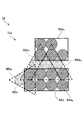
- FIG. 10D shows at least a part of a plurality of light source units provided in the arrangement region 12d having an arbitrary plan view shape in the light source device 1d.
- the light source device 1d has six light source units 4Ad arranged in a rectangular grid pattern and six light source units 4Bd arranged in a triangular grid pattern.
- the light source unit 4Ad is a generic notation for the light source units arranged in a rectangular grid pattern
- the light source unit 4Bd is a generic notation for the light source units arranged in a triangular grid pattern.
- the light source unit 4Ad is displayed by diagonal line hatching
- the light source unit 4Bd is displayed by dot hatching.
- any combination of four or more light source units 4Ad arranged in a rectangular grid pattern is arbitrary.
- the combination of three or more light source units 4 arranged in a triangular lattice pattern is arbitrary.
- the six light source units 4Bd of the light source device 1d are each a part of a combination of three or more arbitrary light source units 4.
- the rectangular grid area 6Ad 1 indicates a region in which the light source unit 4Ad is arranged in a rectangular grid pattern
- the triangular grid regions 6Bd 1 , 6Bd 2 and 6Bd 3 are regions in which the light source unit 4Bd is arranged in a triangular grid pattern, respectively. Is shown.
- FIG. 10E shows at least a part of a plurality of light source units provided in the arrangement region 12e having an arbitrary plan view shape in the light source device 1e.
- the light source device 1e includes 13 light source units 4Ae arranged in a rectangular grid pattern and four light source units 4Be arranged in a triangular grid pattern (specifically, a light source unit 4 arranged in a triangular grid pattern). It has four light source units 4Be), which corresponds to one of them.
- the light source unit 4Ae is a generic notation of the light source units arranged in a rectangular grid pattern
- the light source unit 4Be is a generic notation of the light source units arranged in a triangular grid pattern.
- the light source unit 4Ae is displayed by diagonal line hatching, and the light source unit 4Be is displayed by dot hatching.
- any combination of four or more light source units 4Ae arranged in a rectangular grid pattern is arbitrary.
- the combination of three or more light source units 4 arranged in a triangular lattice pattern is arbitrary.
- each of the four light source units 4Be of the light source device 1e is a part of a combination of any three or more light source units 4.
- the rectangular grid regions 6Ae 1 and 6Ae 2 indicate regions in which the light source portions 4Ae are arranged in a rectangular grid pattern, and the triangular grid regions 6Be 1 , 6Be 2 and 6Be 3 have the light source portions 4Be arranged in a triangular grid pattern, respectively. Shows the area where it is.
- a part of the light source unit 4 arranged in the rectangular grid region 6Ae 1 or 6Ae 2 can also be a part of the triangular grid-like arrangement.
- the arrangement of the plurality of light source units 4 in the embodiment does not necessarily require a rectangular grid-like arrangement and a triangular grid-like arrangement, but if at least the rectangular grid arrangement and the triangular grid arrangement are mixed, the arrangement area in the light source device. Can be miniaturized. Further, the arrangement of the plurality of light source units 4 does not have to be symmetrical. That is, a plurality of light source units 4 can be arranged in an arrangement area having an arbitrary plan view shape. In the above-mentioned modification, the arrangement of the light source unit 4 has been described as an example, but the arrangement of the light guide member in the light guide array unit is also the same.
- FIG. 11 is a diagram showing a comparison between the light source device 1 according to the embodiment and the light source device 1X according to the reference example.
- items are shown in the left column
- the light source device 1 is shown in the center column
- the light source device 1X is shown in the right column.
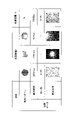
- FIG. 11 shows each experimental data of the maximum illuminance, the uniformity of the illuminance, and the illuminance distribution for each of the three light emission patterns of the light source device 1, and each of the maximum illuminance, the uniformity of the illuminance, and the illuminance distribution of the light source device 1X.
- the experimental data are shown.
- the experimental data on the uniformity of the illuminance in the light source device 1 shows only the experimental results based on the light emission pattern in which all of the plurality of light source units included in the light source device 1 are lit.
- the illuminance uniformity means a value obtained by dividing the minimum illuminance among the illuminances in the four corner regions of the irradiated region by the illuminance in the central region of the irradiated region.
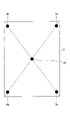
- FIG. 12 is a diagram for explaining the uniformity of illuminance, and is a diagram showing a central region 30 in the irradiated region 3 and corner regions 3a, 3b, 3c, and 3d corresponding to the four corner regions.
- the diffuser plate provided at a position 300 [mm] away from the light source device is irradiated with light from the light source device, and the irradiated area on the diffuser plate is sandwiched between the diffuser plates and from the opposite side to the light source device.
- 3 was photographed with a camera.
- the pixel luminance of the image region corresponding to each of the central region 30 and the corner regions 3a to 3d of the irradiated region 3 is defined as the illuminance of each region.
- the respective sizes of the central region 30 and the corner regions 3a to 3d in the irradiated region 3 are circular regions having a diameter of approximately 10 mm.
- the average value of the luminance values of the plurality of pixels constituting each image region was used.
- Each position of the corner regions 3a to 3d on the irradiated region 3 is a position corresponding to an angle that is 90% of the irradiation angle of view by the light source device.
- the position of the central region 30 is the coordinates (0,0) [mm]
- the position of the corner region 3a is the coordinates (126.0,166.5) [mm]
- the position of the corner region 3b is the coordinates.
- the position of the corner region 3c is the coordinates (126.0, -166.5) [mm]
- the position of the corner region 3d is the coordinates (-126.0, -166). .5) [mm].
- the light emission pattern represents the position of the light source unit that emits light in each of the light source device 1 and the light source device 1X.
- Each of the squares shown in the row of the light emitting pattern in FIG. 11 schematically represents a light source unit including a light emitting element (LED) and a light guide member.
- the light source device 1 arranges a plurality of light source units in a circular shape, and the light source device 1X arranges one light source unit.
- the light source device 1 Since the light source device 1 has a plurality of (63 in this case) light source units, it is possible to emit light in a plurality of light emission patterns according to the number of light source units, and in FIG. 11, three light emission patterns are displayed. are doing. Since the light source device 1X has only one light source unit, one type of light emission pattern is displayed. Further, in FIG. 11, the light source unit that emits light (lights on) is shown by dot hatching, and the light source unit that does not emit light (turns off) is displayed without hatching.
- the illuminance distribution indicates the illuminance distribution of the irradiation light obtained in a part of the irradiated area, and corresponds to the irradiation pattern.
- the illuminance distribution shown in FIG. 11 is obtained by taking an image of irradiation light on a screen provided at a position separated from the light source device by a predetermined distance with a camera, for example.
- the main specifications of the light source device 1 and the light source device 1X are as follows.
- [wt%] shown below represents a weight percent, and means the ratio of the weight of the contained substance to the total weight including the resin which is a base material, and the contained substance.
- the light emitting element is a square shape with a side of 220 [ ⁇ m] in a plan view.
- -Wavelength conversion member Lu 3 Al 5 O 12 : Ce and CaAlSiN 3 : Eu-containing silicone resin-Coating member: Titanium oxide-containing silicone resin-Titanium oxide content of the coating member: 60 [wt%] -Refractive index of titanium oxide of the covering member: 2.54 -Refractive index of silicone resin of covering member: 1.51 -Light diffusing member on the wavelength conversion member: Silicone resin containing titanium oxide-Titanium oxide content of the light diffusing member on the wavelength conversion member: 0.93 [wt%] -Light guide member: TIR lens array including 63 TIR lenses-Material of light guide member: Polycarbonate (refractive index 1.58) Planar view size of light guide member (length L in FIG.
- the light emitting element is a square shape with a side of 1400 [ ⁇ m] in a plan view.
- the specifications of items other than the above in the LED are the same for the light source device 1 and the light source device 1X.
- the maximum illuminance was 2676 [lux] and the uniformity was 41.5 [%].
- the illuminance distribution was obtained in a wide range by the irradiation light of all the light source portions.
- the maximum illuminance was 1250 [lux].
- a local illuminance distribution was obtained only in the portion corresponding to the irradiation light by one light source portion in the central portion.
- the maximum illuminance was 454 [lux].
- a local illuminance distribution was obtained only in the portion corresponding to the irradiation light by one light source portion in the peripheral portion.
- the maximum illuminance was 1500 [lux] and the uniformity was 41.0 [%].
- the illuminance distribution was obtained in a wide range by the irradiation light of one light source unit.
- the light source device 1 has a maximum illuminance of 1.78 times higher than that of the light source device 1X and can obtain 1.78 times brighter irradiation light. It was also found that it is possible to irradiate not only a wide area in the irradiated area but also only a part of the area.
- FIGS. 13A and 13B are diagrams showing an example of the illuminance distribution of the irradiation light by the light source device 1.
- FIG. 13A shows the illuminance distribution of the irradiation light by the light source device 1
- FIG. 13B shows the illuminance distribution of the irradiation light by the light source device 1X.
- the illuminance distribution shown in FIGS. 13A and 13B is an illuminance distribution obtained on the screen when each of the light source device 1 and the light source device 1X irradiates a screen provided at a distance of 500 [mm] with light. ..
- the light source device 1X only one illuminance distribution was obtained by one light emission pattern.
- the light source device 1A seven types of illuminance distributions were obtained by changing the light source unit that irradiates the light among the 63 light source units.
- the number is not limited to seven, and the illuminance distribution corresponding to the number and position of the light source unit that irradiates the light can be obtained from the 63 light source units.
- the configuration of the light guide member including the TIR lens is exemplified, but the present invention is not limited to this.
- the light guide member may include a light guide tube, a refraction type lens, a diffraction type lens, a refractive index distribution type lens, and the like.
- the light source device of the present invention can irradiate a desired illuminated area with light, it can be suitably used for lighting, camera flashes, in-vehicle headlights, head-up display backlights, and the like.
- the light source device of the present invention is not limited to these uses.
Landscapes
- Engineering & Computer Science (AREA)
- General Engineering & Computer Science (AREA)
- Physics & Mathematics (AREA)
- General Physics & Mathematics (AREA)
- Mathematical Physics (AREA)
- Microelectronics & Electronic Packaging (AREA)
- Optics & Photonics (AREA)
- Planar Illumination Modules (AREA)
- Non-Portable Lighting Devices Or Systems Thereof (AREA)
- Led Device Packages (AREA)
- Stroboscope Apparatuses (AREA)
- Studio Devices (AREA)
Priority Applications (6)
| Application Number | Priority Date | Filing Date | Title |
|---|---|---|---|
| JP2022553917A JP7448858B2 (ja) | 2020-10-02 | 2021-09-24 | 光源装置及び導光アレイ部 |
| CN202180066941.3A CN116249934A (zh) | 2020-10-02 | 2021-09-24 | 光源装置和导光阵列部 |
| DE112021004173.8T DE112021004173T5 (de) | 2020-10-02 | 2021-09-24 | Lichtquellenvorrichtung und lichtleiterarrayeinheit |
| US18/188,574 US12044374B2 (en) | 2020-10-02 | 2023-03-23 | Light source device and light guide array unit |
| US18/190,348 US12241608B2 (en) | 2020-10-02 | 2023-03-27 | Light source device and light guide array unit |
| JP2024025996A JP7832511B2 (ja) | 2020-10-02 | 2024-02-22 | 光源装置、車載用光源装置、及び光源装置の駆動方法 |
Applications Claiming Priority (6)
| Application Number | Priority Date | Filing Date | Title |
|---|---|---|---|
| JP2020-168014 | 2020-10-02 | ||
| JP2020168014 | 2020-10-02 | ||
| JP2021-015305 | 2021-02-02 | ||
| JP2021015305 | 2021-02-02 | ||
| JP2021-096777 | 2021-06-09 | ||
| JP2021096777 | 2021-06-09 |
Related Child Applications (1)
| Application Number | Title | Priority Date | Filing Date |
|---|---|---|---|
| US18/188,574 Continuation US12044374B2 (en) | 2020-10-02 | 2023-03-23 | Light source device and light guide array unit |
Publications (1)
| Publication Number | Publication Date |
|---|---|
| WO2022071161A1 true WO2022071161A1 (ja) | 2022-04-07 |
Family
ID=80951618
Family Applications (1)
| Application Number | Title | Priority Date | Filing Date |
|---|---|---|---|
| PCT/JP2021/035200 Ceased WO2022071161A1 (ja) | 2020-10-02 | 2021-09-24 | 光源装置及び導光アレイ部 |
Country Status (5)
| Country | Link |
|---|---|
| US (2) | US12044374B2 (https=) |
| JP (2) | JP7448858B2 (https=) |
| CN (1) | CN116249934A (https=) |
| DE (1) | DE112021004173T5 (https=) |
| WO (1) | WO2022071161A1 (https=) |
Cited By (2)
| Publication number | Priority date | Publication date | Assignee | Title |
|---|---|---|---|---|
| WO2024017950A1 (en) * | 2022-07-22 | 2024-01-25 | Ams International Ag | Device for emitting flash light |
| JP2025084044A (ja) * | 2023-11-21 | 2025-06-02 | 日機株式会社 | レンズ装置及びレンズ装置を有する照明ランプ |
Families Citing this family (4)
| Publication number | Priority date | Publication date | Assignee | Title |
|---|---|---|---|---|
| US12578513B2 (en) * | 2022-11-30 | 2026-03-17 | Panasonic Automotive Systems America, LLC. | Diffuser to improve uniformity of head-up display image brightness |
| US12532078B1 (en) | 2023-06-20 | 2026-01-20 | Amazon Technologies, Inc. | Use of zonal adaptive illumination |
| US12506973B1 (en) | 2023-06-28 | 2025-12-23 | Amazon Technologies, Inc. | Adaptive illumination using vertical cavity surface emitting laser (VCSEL) array |
| WO2025103663A1 (en) * | 2023-11-16 | 2025-05-22 | Ams-Osram Ag | Light source, image recording arrangement, and method for operating an image recording arrangement |
Citations (3)
| Publication number | Priority date | Publication date | Assignee | Title |
|---|---|---|---|---|
| JP2009295434A (ja) * | 2008-06-05 | 2009-12-17 | Epson Imaging Devices Corp | 照明装置、電気光学装置及び電子機器 |
| JP2014157282A (ja) * | 2013-02-15 | 2014-08-28 | Seiko Epson Corp | 照明装置、及びプロジェクター |
| JP2015167512A (ja) * | 2014-03-07 | 2015-09-28 | 株式会社環境フォトニクス | 光照射装置 |
Family Cites Families (41)
| Publication number | Priority date | Publication date | Assignee | Title |
|---|---|---|---|---|
| US7009789B1 (en) | 2000-02-22 | 2006-03-07 | Mems Optical, Inc. | Optical device, system and method |
| US7918583B2 (en) * | 2006-08-16 | 2011-04-05 | Rpc Photonics, Inc. | Illumination devices |
| KR20090115712A (ko) | 2007-02-20 | 2009-11-05 | 칼 짜이스 에스엠테 아게 | 다수의 일차 광원을 갖는 광학 소자 |
| CN101545614B (zh) | 2008-03-26 | 2012-05-23 | 富准精密工业(深圳)有限公司 | 发光二极管灯具 |
| JP2010020995A (ja) | 2008-07-10 | 2010-01-28 | Epson Imaging Devices Corp | 面状照明装置、電気光学装置及び電子機器 |
| CN101684934B (zh) | 2008-09-25 | 2012-12-26 | 富准精密工业(深圳)有限公司 | 发光二极管灯具 |
| EP2287640B1 (en) | 2009-05-25 | 2014-08-20 | LG Innotek Co., Ltd. | Gap member, lens and lighting device having the same |
| KR101028201B1 (ko) | 2009-05-25 | 2011-04-11 | 엘지이노텍 주식회사 | 렌즈 및 이를 구비한 조명 유닛 |
| EP3203306B1 (en) | 2009-07-13 | 2019-07-24 | Harman Professional Denmark ApS | Color-combining illumination device |
| KR100959511B1 (ko) * | 2009-07-15 | 2010-05-27 | 주식회사 네브레이코리아 | 비대칭 반사경 및 집광렌즈를 구비하는 발광다이오드 조명기 |
| DE202010004874U1 (de) | 2010-04-11 | 2010-07-22 | Lightdesign Solutions Gmbh | LED-Modul mit Passiv-LED |
| JP2011222514A (ja) | 2010-04-11 | 2011-11-04 | Sd Hess Lighting Kk | Led照明装置 |
| US8708520B2 (en) * | 2010-04-30 | 2014-04-29 | Seiko Epson Corporation | Illumination device and electronic apparatus |
| EP2718619B8 (en) | 2011-06-10 | 2017-06-28 | Martin Professional ApS | Mechanichal color mixing device |
| US20130064531A1 (en) | 2011-09-13 | 2013-03-14 | Bruce Harold Pillman | Zoom flash with no moving parts |
| SG10201605675WA (en) | 2011-12-20 | 2016-09-29 | Regeneron Pharma | Humanized light chain mice |
| DE102012008638A1 (de) | 2012-05-02 | 2013-11-07 | Heraeus Noblelight Gmbh | Leuchte mit LEDs und Zylinderlinse |
| WO2014045178A1 (en) * | 2012-09-20 | 2014-03-27 | Koninklijke Philips N.V. | Lighting device, lens, system and method |
| FR3002792B1 (fr) * | 2013-03-01 | 2018-07-27 | Legrand France | Appareillage electrique eclairant rotatif |
| US10502391B2 (en) | 2013-12-05 | 2019-12-10 | Harman Professional Denmark Aps | Light collector with a plurality of lenslets packed in an optimized dense circular pattern |
| CN104696883B (zh) | 2013-12-05 | 2019-08-13 | 哈曼专业丹麦公司 | 具有不同光功率的多个合并小透镜的聚光器 |
| JP6270519B2 (ja) | 2014-02-06 | 2018-01-31 | シャープ株式会社 | 光源ユニット及び照明装置 |
| JP6452073B2 (ja) | 2014-02-28 | 2019-01-16 | 日亜化学工業株式会社 | 発光デバイスおよび発光デバイスを有する装置 |
| EP2995852B1 (en) | 2014-09-04 | 2019-03-13 | Harman Professional Denmark ApS | Projecting light fixture with dymamic illumination of beam shaping object |
| KR101737321B1 (ko) * | 2015-03-23 | 2017-05-22 | (주)엔디에스 | 집광 조명장치 |
| EP3420601B1 (en) | 2016-02-26 | 2023-08-02 | Magic Leap, Inc. | Optical system |
| JP6693188B2 (ja) | 2016-03-11 | 2020-05-13 | 岩崎電気株式会社 | 照射器 |
| US10859235B2 (en) * | 2016-06-02 | 2020-12-08 | Federal Signal Corporation | Warning devices with oscillating light patterns |
| JP6678524B2 (ja) | 2016-06-15 | 2020-04-08 | 日立グローバルライフソリューションズ株式会社 | 照明装置 |
| CN205877921U (zh) | 2016-06-22 | 2017-01-11 | 飞利浦灯具(上海)有限公司 | 一种隐藏式灯具及建筑物室内照明结构 |
| EP3290783B1 (en) | 2016-09-04 | 2019-05-15 | Harman Professional Denmark ApS | Light fixture comprising light sources, lenslets and a reto-refector |
| US10514150B2 (en) * | 2017-02-22 | 2019-12-24 | Osram Sylvania Inc. | Solid-state luminaire reflector assembly |
| JP7143740B2 (ja) | 2018-02-07 | 2022-09-29 | オムロン株式会社 | 画像検査装置および照明装置 |
| EP3524967B1 (en) | 2018-02-07 | 2024-01-31 | OMRON Corporation | Image inspection device and lighting device |
| JP7132502B2 (ja) | 2018-03-09 | 2022-09-07 | 日亜化学工業株式会社 | 光源装置 |
| US10770632B2 (en) | 2018-03-09 | 2020-09-08 | Nichia Corporation | Light source device |
| JP7180145B2 (ja) | 2018-06-28 | 2022-11-30 | 富士フイルムビジネスイノベーション株式会社 | 発光素子アレイ、及び光計測システム |
| JP6990265B2 (ja) * | 2019-03-08 | 2022-01-12 | シャープ株式会社 | 画像表示素子 |
| JP7075437B2 (ja) | 2019-04-23 | 2022-05-25 | シャープ株式会社 | 画像表示素子 |
| JP7078600B2 (ja) | 2019-12-19 | 2022-05-31 | 新コスモス電機株式会社 | 警報器 |
| JP2021015305A (ja) | 2020-11-10 | 2021-02-12 | 日東電工株式会社 | 光学部材および画像表示装置 |
-
2021
- 2021-09-24 CN CN202180066941.3A patent/CN116249934A/zh active Pending
- 2021-09-24 WO PCT/JP2021/035200 patent/WO2022071161A1/ja not_active Ceased
- 2021-09-24 JP JP2022553917A patent/JP7448858B2/ja active Active
- 2021-09-24 DE DE112021004173.8T patent/DE112021004173T5/de active Pending
-
2023
- 2023-03-23 US US18/188,574 patent/US12044374B2/en active Active
- 2023-03-27 US US18/190,348 patent/US12241608B2/en active Active
-
2024
- 2024-02-22 JP JP2024025996A patent/JP7832511B2/ja active Active
Patent Citations (3)
| Publication number | Priority date | Publication date | Assignee | Title |
|---|---|---|---|---|
| JP2009295434A (ja) * | 2008-06-05 | 2009-12-17 | Epson Imaging Devices Corp | 照明装置、電気光学装置及び電子機器 |
| JP2014157282A (ja) * | 2013-02-15 | 2014-08-28 | Seiko Epson Corp | 照明装置、及びプロジェクター |
| JP2015167512A (ja) * | 2014-03-07 | 2015-09-28 | 株式会社環境フォトニクス | 光照射装置 |
Cited By (3)
| Publication number | Priority date | Publication date | Assignee | Title |
|---|---|---|---|---|
| WO2024017950A1 (en) * | 2022-07-22 | 2024-01-25 | Ams International Ag | Device for emitting flash light |
| JP2025084044A (ja) * | 2023-11-21 | 2025-06-02 | 日機株式会社 | レンズ装置及びレンズ装置を有する照明ランプ |
| JP7805029B2 (ja) | 2023-11-21 | 2026-01-23 | 日機株式会社 | レンズ装置及びレンズ装置を有する照明ランプ |
Also Published As
| Publication number | Publication date |
|---|---|
| US20230228401A1 (en) | 2023-07-20 |
| US12241608B2 (en) | 2025-03-04 |
| JP7832511B2 (ja) | 2026-03-18 |
| US12044374B2 (en) | 2024-07-23 |
| CN116249934A (zh) | 2023-06-09 |
| US20230228396A1 (en) | 2023-07-20 |
| DE112021004173T5 (de) | 2023-06-01 |
| JP7448858B2 (ja) | 2024-03-13 |
| JP2024055918A (ja) | 2024-04-19 |
| JPWO2022071161A1 (https=) | 2022-04-07 |
Similar Documents
| Publication | Publication Date | Title |
|---|---|---|
| JP7448858B2 (ja) | 光源装置及び導光アレイ部 | |
| JP6812411B2 (ja) | 車両用灯具、車両用灯具制御システムおよびこれらを備えた車両 | |
| US20130258700A1 (en) | Color-mixing convergent optical system | |
| JP2008515138A (ja) | 照明システム | |
| CN102112802A (zh) | 光源装置、照明装置以及显示装置 | |
| JP7575853B2 (ja) | 発光デバイス | |
| US8956009B2 (en) | Apparatus and methods for controlling a three-dimensional optical field | |
| US20090046459A1 (en) | Lighting device | |
| US8915612B2 (en) | Illumination system for spot illumination with reduced symmetry | |
| EP3032310B1 (en) | Light emitting module and light emitting apparatus | |
| KR101951599B1 (ko) | 입체적 이미지를 표출할 수 있는 조명장치 | |
| US10371955B2 (en) | Illumination device having a lenticular lens sheet that is formed in a concave manner having a plano-convex cylindrical convex surface with a light source disposed within the convex surface | |
| US10145527B2 (en) | Laser car lamp and night vision system using the same | |
| WO2014203725A1 (ja) | 照明装置 | |
| JP6121745B2 (ja) | 面照明発光装置 | |
| KR20160059707A (ko) | 발광 소자 패키지 및 이를 포함하는 백 라이트 유닛 | |
| KR20150108213A (ko) | 조명 장치 | |
| JP6138705B2 (ja) | 照明装置及び表示装置 | |
| KR20230047084A (ko) | 조명 장치 | |
| CN118984968A (zh) | 面发光装置、显示装置以及照明装置 | |
| JP2023004228A (ja) | 発光装置、面光源装置および表示装置 | |
| JP2022168629A (ja) | 面光源装置および表示装置 | |
| JP2020194646A (ja) | 照明装置 | |
| JP2017191693A (ja) | 面発光装置、および画像形成装置 |
Legal Events
| Date | Code | Title | Description |
|---|---|---|---|
| 121 | Ep: the epo has been informed by wipo that ep was designated in this application |
Ref document number: 21875463 Country of ref document: EP Kind code of ref document: A1 |
|
| ENP | Entry into the national phase |
Ref document number: 2022553917 Country of ref document: JP Kind code of ref document: A |
|
| 122 | Ep: pct application non-entry in european phase |
Ref document number: 21875463 Country of ref document: EP Kind code of ref document: A1 |