WO2022065425A1 - クランクシャフト - Google Patents
クランクシャフト Download PDFInfo
- Publication number
- WO2022065425A1 WO2022065425A1 PCT/JP2021/035059 JP2021035059W WO2022065425A1 WO 2022065425 A1 WO2022065425 A1 WO 2022065425A1 JP 2021035059 W JP2021035059 W JP 2021035059W WO 2022065425 A1 WO2022065425 A1 WO 2022065425A1
- Authority
- WO
- WIPO (PCT)
- Prior art keywords
- crankshaft
- less
- hardness
- journal
- pin
- Prior art date
- Legal status (The legal status is an assumption and is not a legal conclusion. Google has not performed a legal analysis and makes no representation as to the accuracy of the status listed.)
- Ceased
Links
Images





Classifications
-
- F—MECHANICAL ENGINEERING; LIGHTING; HEATING; WEAPONS; BLASTING
- F16—ENGINEERING ELEMENTS AND UNITS; GENERAL MEASURES FOR PRODUCING AND MAINTAINING EFFECTIVE FUNCTIONING OF MACHINES OR INSTALLATIONS; THERMAL INSULATION IN GENERAL
- F16C—SHAFTS; FLEXIBLE SHAFTS; ELEMENTS OR CRANKSHAFT MECHANISMS; ROTARY BODIES OTHER THAN GEARING ELEMENTS; BEARINGS
- F16C3/00—Shafts; Axles; Cranks; Eccentrics
- F16C3/04—Crankshafts, eccentric-shafts; Cranks, eccentrics
- F16C3/06—Crankshafts
-
- C—CHEMISTRY; METALLURGY
- C22—METALLURGY; FERROUS OR NON-FERROUS ALLOYS; TREATMENT OF ALLOYS OR NON-FERROUS METALS
- C22C—ALLOYS
- C22C38/00—Ferrous alloys, e.g. steel alloys
-
- C—CHEMISTRY; METALLURGY
- C22—METALLURGY; FERROUS OR NON-FERROUS ALLOYS; TREATMENT OF ALLOYS OR NON-FERROUS METALS
- C22C—ALLOYS
- C22C38/00—Ferrous alloys, e.g. steel alloys
- C22C38/02—Ferrous alloys, e.g. steel alloys containing silicon
-
- C—CHEMISTRY; METALLURGY
- C22—METALLURGY; FERROUS OR NON-FERROUS ALLOYS; TREATMENT OF ALLOYS OR NON-FERROUS METALS
- C22C—ALLOYS
- C22C38/00—Ferrous alloys, e.g. steel alloys
- C22C38/04—Ferrous alloys, e.g. steel alloys containing manganese
-
- C—CHEMISTRY; METALLURGY
- C22—METALLURGY; FERROUS OR NON-FERROUS ALLOYS; TREATMENT OF ALLOYS OR NON-FERROUS METALS
- C22C—ALLOYS
- C22C38/00—Ferrous alloys, e.g. steel alloys
- C22C38/06—Ferrous alloys, e.g. steel alloys containing aluminium
-
- C—CHEMISTRY; METALLURGY
- C22—METALLURGY; FERROUS OR NON-FERROUS ALLOYS; TREATMENT OF ALLOYS OR NON-FERROUS METALS
- C22C—ALLOYS
- C22C38/00—Ferrous alloys, e.g. steel alloys
- C22C38/18—Ferrous alloys, e.g. steel alloys containing chromium
- C22C38/38—Ferrous alloys, e.g. steel alloys containing chromium with more than 1.5% by weight of manganese
-
- C—CHEMISTRY; METALLURGY
- C22—METALLURGY; FERROUS OR NON-FERROUS ALLOYS; TREATMENT OF ALLOYS OR NON-FERROUS METALS
- C22C—ALLOYS
- C22C38/00—Ferrous alloys, e.g. steel alloys
- C22C38/60—Ferrous alloys, e.g. steel alloys containing lead, selenium, tellurium, or antimony, or more than 0.04% by weight of sulfur
-
- F—MECHANICAL ENGINEERING; LIGHTING; HEATING; WEAPONS; BLASTING
- F16—ENGINEERING ELEMENTS AND UNITS; GENERAL MEASURES FOR PRODUCING AND MAINTAINING EFFECTIVE FUNCTIONING OF MACHINES OR INSTALLATIONS; THERMAL INSULATION IN GENERAL
- F16C—SHAFTS; FLEXIBLE SHAFTS; ELEMENTS OR CRANKSHAFT MECHANISMS; ROTARY BODIES OTHER THAN GEARING ELEMENTS; BEARINGS
- F16C3/00—Shafts; Axles; Cranks; Eccentrics
- F16C3/04—Crankshafts, eccentric-shafts; Cranks, eccentrics
- F16C3/06—Crankshafts
- F16C3/08—Crankshafts made in one piece
-
- F—MECHANICAL ENGINEERING; LIGHTING; HEATING; WEAPONS; BLASTING
- F16—ENGINEERING ELEMENTS AND UNITS; GENERAL MEASURES FOR PRODUCING AND MAINTAINING EFFECTIVE FUNCTIONING OF MACHINES OR INSTALLATIONS; THERMAL INSULATION IN GENERAL
- F16C—SHAFTS; FLEXIBLE SHAFTS; ELEMENTS OR CRANKSHAFT MECHANISMS; ROTARY BODIES OTHER THAN GEARING ELEMENTS; BEARINGS
- F16C33/00—Parts of bearings; Special methods for making bearings or parts thereof
- F16C33/02—Parts of sliding-contact bearings
- F16C33/04—Brasses; Bushes; Linings
- F16C33/06—Sliding surface mainly made of metal
-
- C—CHEMISTRY; METALLURGY
- C21—METALLURGY OF IRON
- C21D—MODIFYING THE PHYSICAL STRUCTURE OF FERROUS METALS; GENERAL DEVICES FOR HEAT TREATMENT OF FERROUS OR NON-FERROUS METALS OR ALLOYS; MAKING METAL MALLEABLE, e.g. BY DECARBURISATION OR TEMPERING
- C21D1/00—General methods or devices for heat treatment, e.g. annealing, hardening, quenching or tempering
- C21D1/06—Surface hardening
- C21D1/09—Surface hardening by direct application of electrical or wave energy; by particle radiation
- C21D1/10—Surface hardening by direct application of electrical or wave energy; by particle radiation by electric induction
-
- C—CHEMISTRY; METALLURGY
- C21—METALLURGY OF IRON
- C21D—MODIFYING THE PHYSICAL STRUCTURE OF FERROUS METALS; GENERAL DEVICES FOR HEAT TREATMENT OF FERROUS OR NON-FERROUS METALS OR ALLOYS; MAKING METAL MALLEABLE, e.g. BY DECARBURISATION OR TEMPERING
- C21D1/00—General methods or devices for heat treatment, e.g. annealing, hardening, quenching or tempering
- C21D1/34—Methods of heating
- C21D1/42—Induction heating
-
- C—CHEMISTRY; METALLURGY
- C21—METALLURGY OF IRON
- C21D—MODIFYING THE PHYSICAL STRUCTURE OF FERROUS METALS; GENERAL DEVICES FOR HEAT TREATMENT OF FERROUS OR NON-FERROUS METALS OR ALLOYS; MAKING METAL MALLEABLE, e.g. BY DECARBURISATION OR TEMPERING
- C21D9/00—Heat treatment, e.g. annealing, hardening, quenching or tempering, adapted for particular articles; Furnaces therefor
- C21D9/30—Heat treatment, e.g. annealing, hardening, quenching or tempering, adapted for particular articles; Furnaces therefor for crankshafts; for camshafts
-
- F—MECHANICAL ENGINEERING; LIGHTING; HEATING; WEAPONS; BLASTING
- F16—ENGINEERING ELEMENTS AND UNITS; GENERAL MEASURES FOR PRODUCING AND MAINTAINING EFFECTIVE FUNCTIONING OF MACHINES OR INSTALLATIONS; THERMAL INSULATION IN GENERAL
- F16C—SHAFTS; FLEXIBLE SHAFTS; ELEMENTS OR CRANKSHAFT MECHANISMS; ROTARY BODIES OTHER THAN GEARING ELEMENTS; BEARINGS
- F16C2202/00—Solid materials defined by their properties
- F16C2202/02—Mechanical properties
- F16C2202/04—Hardness
-
- F—MECHANICAL ENGINEERING; LIGHTING; HEATING; WEAPONS; BLASTING
- F16—ENGINEERING ELEMENTS AND UNITS; GENERAL MEASURES FOR PRODUCING AND MAINTAINING EFFECTIVE FUNCTIONING OF MACHINES OR INSTALLATIONS; THERMAL INSULATION IN GENERAL
- F16C—SHAFTS; FLEXIBLE SHAFTS; ELEMENTS OR CRANKSHAFT MECHANISMS; ROTARY BODIES OTHER THAN GEARING ELEMENTS; BEARINGS
- F16C2204/00—Metallic materials; Alloys
- F16C2204/60—Ferrous alloys, e.g. steel alloys
- F16C2204/62—Low carbon steel, i.e. carbon content below 0.4 wt%
-
- F—MECHANICAL ENGINEERING; LIGHTING; HEATING; WEAPONS; BLASTING
- F16—ENGINEERING ELEMENTS AND UNITS; GENERAL MEASURES FOR PRODUCING AND MAINTAINING EFFECTIVE FUNCTIONING OF MACHINES OR INSTALLATIONS; THERMAL INSULATION IN GENERAL
- F16C—SHAFTS; FLEXIBLE SHAFTS; ELEMENTS OR CRANKSHAFT MECHANISMS; ROTARY BODIES OTHER THAN GEARING ELEMENTS; BEARINGS
- F16C2240/00—Specified values or numerical ranges of parameters; Relations between them
- F16C2240/40—Linear dimensions, e.g. length, radius, thickness, gap
- F16C2240/54—Surface roughness
-
- F—MECHANICAL ENGINEERING; LIGHTING; HEATING; WEAPONS; BLASTING
- F16—ENGINEERING ELEMENTS AND UNITS; GENERAL MEASURES FOR PRODUCING AND MAINTAINING EFFECTIVE FUNCTIONING OF MACHINES OR INSTALLATIONS; THERMAL INSULATION IN GENERAL
- F16C—SHAFTS; FLEXIBLE SHAFTS; ELEMENTS OR CRANKSHAFT MECHANISMS; ROTARY BODIES OTHER THAN GEARING ELEMENTS; BEARINGS
- F16C2240/00—Specified values or numerical ranges of parameters; Relations between them
- F16C2240/94—Volume
-
- Y—GENERAL TAGGING OF NEW TECHNOLOGICAL DEVELOPMENTS; GENERAL TAGGING OF CROSS-SECTIONAL TECHNOLOGIES SPANNING OVER SEVERAL SECTIONS OF THE IPC; TECHNICAL SUBJECTS COVERED BY FORMER USPC CROSS-REFERENCE ART COLLECTIONS [XRACs] AND DIGESTS
- Y02—TECHNOLOGIES OR APPLICATIONS FOR MITIGATION OR ADAPTATION AGAINST CLIMATE CHANGE
- Y02P—CLIMATE CHANGE MITIGATION TECHNOLOGIES IN THE PRODUCTION OR PROCESSING OF GOODS
- Y02P10/00—Technologies related to metal processing
- Y02P10/25—Process efficiency
Definitions
- the present invention relates to a crankshaft.
- the crankshaft may be surface hardened by induction hardening or soft nitriding in order to improve fatigue strength and wear resistance.
- the shaft part, the bush part, the flywheel part, the pin part, and the web part are separately manufactured, welded and integrated, and then quenched and tempered and then machined.
- a method for manufacturing a crankshaft is disclosed.
- crank shaft formed of non-tempered steel having a low carbon content was subjected to induction hardening and tempering so that the quenching hardness was less than HV400 to 500. Later, a surface treatment method for a crank shaft that is surface-plastically processed so that the hardness of the surface-hardened layer is HV500 to 700 is disclosed.
- Japanese Patent No. 433207 discloses a high-strength steel for large forged steel products and a large crank shaft made of the same steel.
- the publication describes that steel for forgings is heated to 870 ° C., cooled (quenched) at a cooling rate of 20 ° C./min, and tempered at 580 to 630 ° C.
- the crankshaft is required to have seizure resistance in addition to fatigue strength and wear resistance.
- the viscosity of lubricating oil has been reduced and the sliding portion of the crankshaft has become thinner, and the crankshaft is required to have better seizure resistance.
- An object of the present invention is to provide a crankshaft having excellent seizure resistance.
- the crankshaft according to the embodiment of the present invention is a crankshaft including a journal portion and a pin portion, and has a chemical composition of 0.35 to 0.40% by mass, C: 0.35 to 0.40%, and Si: 0.70% or less.
- Mn 1.00 to 2.00%
- Cr 0.50% or less
- Al 0.050% or less
- N 0.020% or less
- P 0.020% or less
- S 0.005 to 0.200%
- each of the journal part and the pin part has a surface structure containing tempered martensite of 80% by volume or more, and the surface hardness is HV450 or less. Is.
- crankshaft having excellent seizure resistance can be obtained.
- FIG. 1 is a schematic view of a crankshaft according to an embodiment of the present invention.
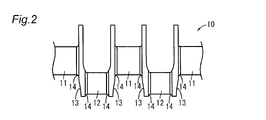
- FIG. 2 is an enlarged view of a part of the journal part and the pin part.
- FIG. 3 is a flow chart showing an example of the method for manufacturing the crankshaft of FIG.
- FIG. 4 is a schematic diagram of the evaluation device used in the seizure test.
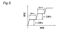
- FIG. 5 is a schematic diagram of the time change of the surface pressure applied to the test shaft.
- FIG. 6 is a graph showing the relationship between the surface hardness and the seizure surface pressure.
- FIG. 7 is a graph showing the relationship between the surface hardness and the seizure surface pressure.
- FIG. 1 is a schematic view of a crankshaft 10 according to an embodiment of the present invention.
- the crankshaft 10 includes a journal portion 11, a pin portion 12, and an arm portion 13.
- the journal unit 11 is connected to a cylinder block (not shown).
- the pin portion 12 is connected to a connecting rod (not shown).
- the arm portion 13 connects the journal portion 11 and the pin portion 12.
- the journal portion 11 and the pin portion 12 slide with the bearings formed on the cylinder block and the connecting rod, respectively.
- crankshaft 10 has the chemical composition described below. In the following description, "%" of the element content means mass%.
- Carbon (C) improves the hardness of steel and contributes to the improvement of fatigue strength. On the other hand, if the C content is too high, the shrinkage resistance and machinability deteriorate. Therefore, the C content is 0.35 to 0.40%.
- Si 0.70% or less Silicon (Si) deoxidizes steel. On the other hand, if the Si content is too high, the machinability is lowered. Therefore, the Si content is 0.70% or less.
- the lower limit of the Si content is preferably 0.01%.
- the upper limit of the Si content is preferably 0.50%.
- Mn 1.00 to 2.00%
- Mn Manganese
- Chromium (Cr) enhances the hardenability of steel. On the other hand, if the Cr content is too high, the machinability is lowered. Therefore, the Cr content is 0.50% or less.
- the lower limit of the Cr content is preferably 0.01%, more preferably 0.05%.
- the upper limit of the Cr content is preferably 0.30%.
- Al 0.050% or less Aluminum (Al) deoxidizes steel. On the other hand, if the Al content is too high, the machinability is lowered. Therefore, the Al content is 0.050% or less.
- the lower limit of the Al content is preferably 0.001%.
- N 0.020% or less Nitrogen (N) is an impurity. N reduces the hot ductility of the steel. Therefore, the N content is 0.020% or less. On the other hand, if the N content is excessively limited, the smelting cost increases.
- the lower limit of the N content is preferably 0.001%, more preferably 0.005%.
- P 0.020% or less Phosphorus (P) is an impurity. P reduces the shrinkage resistance of the steel. Therefore, the P content is 0.020% or less.
- S 0.005 to 0.200% Sulfur (S) forms MnS and enhances the machinability of steel. On the other hand, if the S content is too high, the hot workability of the steel deteriorates. Therefore, the S content is 0.005 to 0.200%.
- the rest of the chemical composition of the crankshaft 10 is Fe and impurities.
- Impurities here refer to elements mixed from ores and scraps used as raw materials for steel, or elements mixed from the environment of the manufacturing process.
- Each of the journal portion 11 and the pin portion 12 has a surface structure containing 80% by volume or more of tempered martensite, and has a surface hardness of HV450 or less.
- the seizure resistance is remarkably improved.
- cementite shall be treated as a structure independent of tempered martensite.
- the surface textures of the journal portion 11 and the pin portion 12 preferably contain 10% by volume or more of cementite.
- the volume fraction of cementite in the surface structure of the journal portion 11 and the pin portion 12 is preferably 12% by volume or more, more preferably 15% by volume or more.
- Cementite is preferably finely dispersed in the form of particles.
- the hardness of the surfaces of the journal portion 11 and the pin portion 12 is measured according to JIS Z 2244 (2009).
- the test force is 300 gf (2.942 N).
- the surface hardness of the journal portion 11 and the pin portion 12 is preferably HV400 or less, more preferably HV350 or less, still more preferably HV300 or less, still more preferably HV250 or less.
- the lower limit of the hardness of the surfaces of the journal portion 11 and the pin portion 12 is not particularly set, but is, for example, HV180, more preferably HV200.
- journal part 11 and the pin part 12 have an arbitrary structure other than the surface structure. That is, the journal portion 11 and the pin portion 12 may be a structure containing 80% by volume or more of tempered martensite up to the core part, or may be a structure containing 80% by volume or more of tempered martensite only on the surface or the vicinity of the surface. There may be.
- journal portion 11 and the pin portion 12 other than the surface is arbitrary. That is, the journal portion 11 and the pin portion 12 may have a hardness of HV450 or less up to the core portion, or may have a hardness of HV450 or less only on the surface or in the vicinity of the surface.
- each of the journal portion 11 and the pin portion 12 has the above-mentioned structure and hardness in the region from the surface to a depth of 1.0 mm.
- the above-mentioned structure and the above-mentioned hardness are obtained in the region from the surface to a depth of 2.0 mm, and more preferably, the above-mentioned structure and the above-mentioned hardness are obtained in the region from the surface to a depth of 3.0 mm. be.
- each of the journal portion 11 and the pin portion 12 has a surface roughness Ra of 0.100 ⁇ m or less.
- the surface roughness Ra of the journal portion 11 and the pin portion 12 is more preferably 0.080 ⁇ m or less, and further preferably 0.060 ⁇ m or less.
- FIG. 2 is an enlarged view of a part of the journal portion 11 and the pin portion 12 of the crankshaft 10.
- the crankshaft 10 further includes a fillet portion 14 formed at a boundary between the journal portion 11 and the arm portion 13 and a boundary between the pin portion 12 and the arm portion 13.
- the fillet portion adjacent to the journal portion 11 and the fillet portion adjacent to the pin portion 12 are not distinguished, and both are referred to as a fillet portion 14.
- the fillet portion 14 is formed in a smooth shape in order to alleviate stress concentration.
- the fillet portion 14 is a portion of the crankshaft 10 to which the strongest stress is applied.
- the fatigue characteristics of the crankshaft 10 are dominated by the influence of the fatigue strength of the fillet portion 14. Further, the bending fatigue, which is a problem in the crankshaft 10, is dominated by the influence of the characteristics of the surface layer portion of the component. Therefore, from the viewpoint of increasing the fatigue strength of the crankshaft 10, it is preferable to increase the hardness of the surface layer portion of the fillet portion 14.
- the hardness of the fillet portion 14 from the surface to a depth of 2 mm is HV580 or more.
- the hardness of the fillet portion 14 from the surface to a depth of 2 mm is more preferably HV600 or more, still more preferably HV650 or more.
- the upper limit of the hardness from the surface of the fillet portion 14 to the depth of 2 mm is not particularly set, but is, for example, HV800.
- the hardness of the region deeper than 2.0 mm from the surface of the fillet portion 14 is arbitrary. That is, the fillet portion 14 may have a hardness of HV580 or more up to the core portion, or may have a hardness of only the region from the surface to a depth of 2 mm HV580 or more. However, in order to obtain a more stable effect, it is more preferable that the hardness of the region from the surface to the depth of 3.0 mm is HV580 or more, HV600 or more, or HV650 or more, and the depth from the surface is 4.0 mm. It is more preferable that the hardness of the region up to is HV580 or more, HV600 or more, or HV650 or more.
- a sample having a cross section (longitudinal cross section) parallel to the axial direction of the crankshaft 10 as a measurement surface shall be taken, and the measurement surface shall be measured in accordance with JIS Z 2244 (2009). ..
- the test force is 300 gf (2.942 N).
- the organization of the fillet section 14 is arbitrary. However, when the hardness of the surface layer portion of the fillet portion 14 is set to HV580 or more in order to improve the fatigue strength of the crankshaft 10, it is preferable that the structure of the region is a structure containing martensite. More specifically, it is preferable that the structure of the region is a structure containing 80% by volume or more of martensite. The volume fraction of martensite in the region is more preferably 90% by volume or more, still more preferably 95% by volume or more.
- Martensite (fresh martensite) here means martensite as it is hardened or low-temperature tempered martensite for strain removal, and shall be distinguished from “tempered martensite”.
- "Martensite” and “tempering martensite” can be distinguished by observing the amount and dispersion state of precipitated metal carbides and cementite with a microscope or the like. Further, in specifying the structure of the surface layer of the fillet part 14, cementite shall be treated as a structure independent of martensite.
- the structure and hardness of the parts other than the journal part 11, the pin part 12, and the fillet part 14 are arbitrary.
- crankshaft manufacturing method Next, an example of a method for manufacturing the crankshaft 10 will be described.
- the manufacturing method described below is merely an example, and does not limit the manufacturing method of the crankshaft 10.
- FIG. 3 is a flow chart showing an example of a method for manufacturing the crankshaft 10.
- This manufacturing method includes a process of preparing a material (step S1), a hot forging process (step S2), a heat treatment process (step S3), a machining process (step S4), a quenching process (step S5), and a tempering process (step). S6) and a finishing process (step S7) are provided.
- step S1 a process of preparing a material
- step S2 a hot forging process
- step S3 a heat treatment process
- step S4 a machining process
- step S5 a quenching process
- step S5 quenching process
- a tempering process step S6
- step S7 a finishing process
- the material is, for example, steel bar.
- the material can be produced, for example, by continuous casting or slab rolling of molten steel having a predetermined chemical composition.
- the material is hot forged to give a rough shape to the crankshaft (step S2). Hot forging may be performed separately for rough forging and finish forging.
- step S3 Heat treatment such as normalizing is performed on the rough crankshaft manufactured by hot forging as necessary (step S3).
- the heat treatment step (step S3) is an arbitrary step, and this step may be omitted depending on the required characteristics of the crankshaft and the like.
- Machining includes cutting, grinding, drilling, and the like. This process produces an intermediate product with a shape similar to that of the final product.
- the intermediate product of the machined crankshaft is quenched (step S5). Specifically, it is heated to a predetermined heating temperature and then rapidly cooled. At this time, the intermediate product may be heated locally by a high-frequency induction heating device or the entire intermediate product may be heated by a heat treatment furnace. However, when locally heating, it is preferable that at least the journal portion 11, the pin portion 12, and the fillet portion 14 are heated. This quenching may be carried out in a plurality of times.
- the heating temperature is preferably Ac 3 points or more, and more preferably 900 ° C. or more.
- the hardness of the surface layer portion of the fillet portion 14 is HV580 or more.
- the hardness of the surface layer portion of the fillet portion 14 can be adjusted by the chemical composition of the material and the cooling rate at the time of quenching. Specifically, if the content of an element that contributes to hardenability such as C is increased or the cooling rate is increased, the hardness of the surface layer portion of the fillet portion 14 increases. If the hardness of the surface layer portion of the fillet portion 14 does not reach HV580 due to quenching, plastic working such as a fillet roll may be performed to improve the hardness of the surface layer portion of the fillet portion 14.
- Temper the hardened intermediate product (step S6). Specifically, for example, the temperature is maintained at 330 to 750 ° C. for a predetermined time. Tempering is performed so that the hardness of the surfaces of the journal portion 11 and the pin portion 12 is HV450 or less. The higher the heating temperature or the longer the holding time, the lower the hardness can be. If the heating temperature is less than 330 ° C., the hardness may not be sufficiently lowered. On the other hand, if the heating temperature is higher than 750 ° C., austenite may be generated in the tissue. Since this austenite transforms into re-quenched martensite and ferrite pearlite during cooling, it may not be possible to sufficiently reduce the hardness.
- the heating temperature is preferably 550 to 650 ° C.
- the holding time is, for example, 10 to 120 minutes.
- journal portion 11 and the pin portion 12 it is preferable to heat the journal portion 11 and the pin portion 12 using a high-frequency induction heating device so that the fillet portion 14 is not heated as much as possible.
- This tempering may be carried out in a plurality of times.
- the heating location can be adjusted according to the shape of the induction coil, the distance between the induction coil and the target portion, the output frequency, and the like.
- quenching and tempering may be performed a plurality of times, and other heat treatments may be performed in addition to quenching and tempering.
- other heat treatments may be performed in addition to quenching and tempering.
- low-temperature tempering at a temperature that does not significantly affect the surface texture and hardness may be carried out.
- the tempered intermediate product is finished as necessary (step S7).
- the journal portion 11 and the pin portion 12 are ground and wrapped to adjust the surface shape.
- crankshaft 10 The configuration of the crankshaft 10 according to the embodiment of the present invention and an example of the manufacturing method thereof have been described above. According to this embodiment, a crankshaft having excellent seizure resistance can be obtained.
- the material was heated to 1250 ° C. and then processed by hot forging (finishing temperature of 1075 ° C.) to an outer diameter of 63 mm and a length of 570 mm. After air cooling to room temperature, cutting and scale removal were performed. Then, induction hardening was performed by heating to a temperature of 3 points or more of Ac by a high frequency induction heating device and then cooling with water. The frequency and the like were adjusted so that the thickness of the hardened layer was 3.0 mm or more. Then, tempering was performed by heating at 620 ° C or 350 ° C for 90 minutes and then air-cooling. As a finishing process, the test shaft was ground and wrapped so that the surface roughness Ra was 0.040 to 0.100 ⁇ m.
- a seizure test was carried out using the prepared test shaft.
- the seizure test was carried out using a crank metal wear and seizure resistance evaluation device manufactured by Shinko Engineering Co., Ltd.
- a schematic diagram of the evaluation device 20 is shown in FIG.
- the test shaft TP was inserted into a plurality of bearings 21, and the test shaft TP was rotated at 8000 rpm by a motor (not shown) while refueling the bearings 21.
- the metal of the bearing used was an engine bearing (Al alloy) manufactured by Taiho Kogyo Co., Ltd.
- the lubricating oil was 0W-16 or 0W-8, and the lubrication temperature was 130 ° C.
- FIG. 5 schematically shows the time change of the surface pressure applied to the test axis TP.
- the holding time at the same surface pressure was 3 minutes, and the surface pressure increase width per step was 4.0 MPa. It was determined that seizure occurred when the surface temperature of the bearing exceeded the specified value or the torque applied to the test shaft exceeded the specified value.
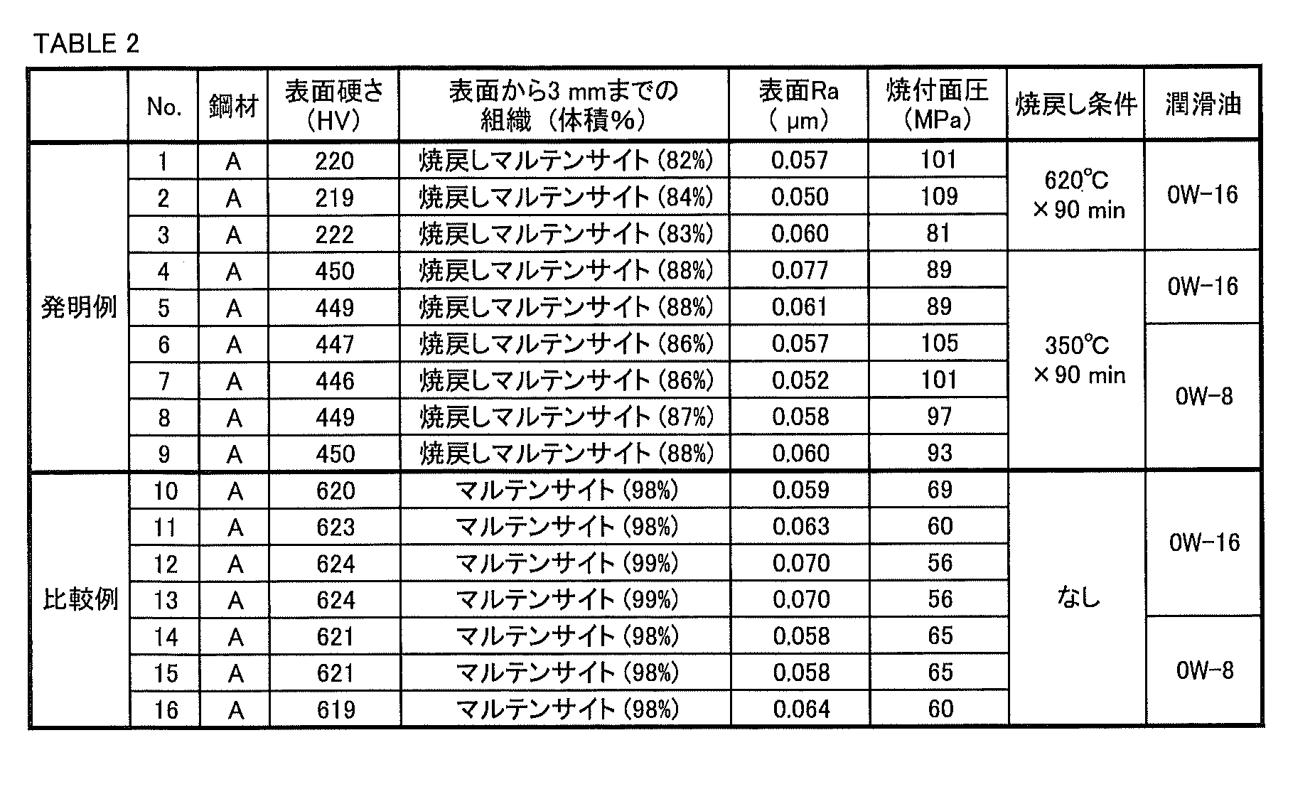
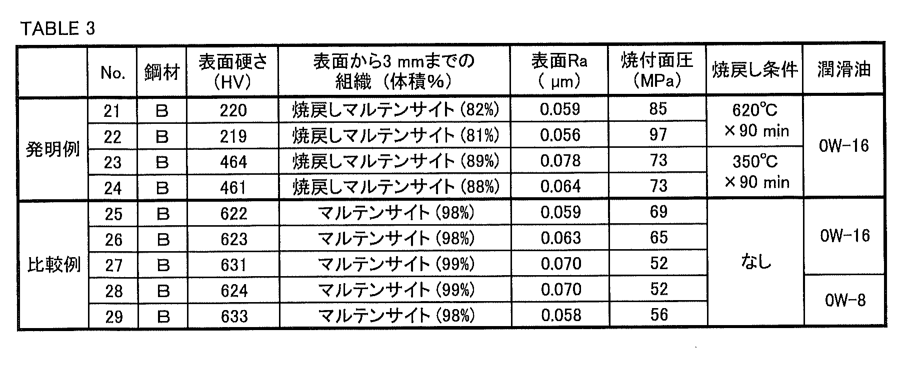
- Tables 2 and 3 show the surface hardness, surface texture, surface roughness Ra, tempering conditions, tempering surface pressure, tempering conditions, etc. of each test shaft.
- FIGS. 6 and 7 show the relationship between the surface hardness and the seizure surface pressure created from the data of 0W-16 for the lubricating oil.
- FIG. 6 relates to steel material A
- FIG. 7 relates to steel material B.
- the test shaft having a surface hardness of HV450 or less had a higher seizure surface pressure than the test shaft of the comparative example, and showed excellent seizure resistance.
- the seizure surface pressure tended to increase as the surface hardness decreased.
- the above-described embodiment is merely an example for carrying out the present invention. Therefore, the present invention is not limited to the above-described embodiment, and the above-mentioned embodiment can be appropriately modified and carried out within a range not deviating from the gist thereof.
Landscapes
- Chemical & Material Sciences (AREA)
- Engineering & Computer Science (AREA)
- Mechanical Engineering (AREA)
- Materials Engineering (AREA)
- Metallurgy (AREA)
- Organic Chemistry (AREA)
- General Engineering & Computer Science (AREA)
- Ocean & Marine Engineering (AREA)
- Shafts, Cranks, Connecting Bars, And Related Bearings (AREA)
- Heat Treatment Of Articles (AREA)
Abstract
Description
図1は、本発明の一実施形態によるクランクシャフト10の概略図である。クランクシャフト10は、ジャーナル部11、ピン部12、及びアーム部13を備えている。
クランクシャフト10は、以下に説明する化学組成を有する。以下の説明において、元素の含有量の「%」は、質量%を意味する。
炭素(C)は、鋼の硬さを向上させ、疲労強度の向上に寄与する。一方、C含有量が高すぎると、耐焼割れ性及び被削性が低下する。したがって、C含有量は0.35~0.40%である。
シリコン(Si)は、鋼を脱酸する。一方、Si含有量が高すぎると、被削性が低下する。したがって、Si含有量は0.70%以下である。Si含有量の下限は、好ましくは0.01%である。Si含有量の上限は、好ましくは0.50%である。
マンガン(Mn)は、鋼の焼入れ性を高める。一方、Mn含有量が高すぎると、被削性が低下する。したがって、Mn含有量は1.00~2.00%である。
クロム(Cr)は、鋼の焼入れ性を高める。一方、Cr含有量が高すぎると、被削性が低下する。したがって、Cr含有量は0.50%以下である。Cr含有量の下限は、好ましくは0.01%であり、さらに好ましくは0.05%である。Cr含有量の上限は、好ましくは0.30%である。
アルミニウム(Al)は、鋼を脱酸する。一方、Al含有量が高すぎると、被削性が低下する。したがって、Al含有量は0.050%以下である。Al含有量の下限は、好ましくは0.001%である。
窒素(N)は、不純物である。Nは、鋼の熱間延性を低下させる。したがって、N含有量は0.020%以下である。一方、N含有量を過剰に制限すると製錬コストが増加する。N含有量の下限は、好ましくは0.001%であり、さらに好ましくは0.005%である。
リン(P)は、不純物である。Pは、鋼の耐焼割れ性を低下させる。したがって、P含有量は0.020%以下である。
硫黄(S)は、MnSを形成し、鋼の被削性を高める。一方、S含有量が高すぎると、鋼の熱間加工性が低下する。したがって、S含有量は0.005~0.200%である。
ジャーナル部11及びピン部12の各々は、表面の組織が80体積%以上の焼戻しマルテンサイトを含む組織であり、表面の硬さがHV450以下である。ジャーナル部11及びピン部12の表面の組織を80体積%以上の焼戻しマルテンサイトを含む組織とし、かつ、表面の硬さをHV450以下にすることで、耐焼付性が顕著に向上する。
次に、クランクシャフト10の製造方法の一例を説明する。以下に説明する製造方法は、あくまでも例示であって、クランクシャフト10の製造方法を限定するものではない。

11 ジャーナル部
12 ピン部
13 アーム部
14 フィレット部
Claims (6)
- ジャーナル部及びピン部を備えるクランクシャフトであって、
化学組成が、質量%で、
C :0.35~0.40%、
Si:0.70%以下、
Mn:1.00~2.00%、
Cr:0.50%以下、
Al:0.050%以下、
N :0.020%以下、
P :0.020%以下、
S :0.005~0.200%、
残部:Fe及び不純物、であり、
前記ジャーナル部及び前記ピン部の各々は、表面の組織が80体積%以上の焼戻しマルテンサイトを含む組織であり、表面の硬さがHV450以下である、クランクシャフト。 - 請求項1に記載のクランクシャフトであって、
フィレット部をさらに備え、
前記フィレット部は、表面から深さ2.0mmまでの硬さがHV580以上である、クランクシャフト。 - 請求項2に記載のクランクシャフトであって、
前記フィレット部は、表面から深さ2.0mmまでの組織が、80体積%以上のマルテンサイトを含む組織である、クランクシャフト。 - 請求項1~3のいずれか一項に記載のクランクシャフトであって、
前記ジャーナル部及び前記ピン部の各々の表面の硬さがHV250以下である、クランクシャフト。 - 請求項1~4のいずれか一項に記載のクランクシャフトであって、
前記ジャーナル部及び前記ピン部の各々の表面の組織が、10体積%以上のセメンタイトをさらに含む、クランクシャフト。 - 請求項1~5のいずれか一項に記載のクランクシャフトであって、
前記ジャーナル部及び前記ピン部の各々の表面粗さRaが0.100μm以下である、クランクシャフト。
Priority Applications (3)
| Application Number | Priority Date | Filing Date | Title |
|---|---|---|---|
| JP2022552066A JP7462781B2 (ja) | 2020-09-28 | 2021-09-24 | クランクシャフト |
| CN202180058495.1A CN116323992B (zh) | 2020-09-28 | 2021-09-24 | 曲轴 |
| US18/005,877 US12352309B2 (en) | 2020-09-28 | 2021-09-24 | Crankshaft |
Applications Claiming Priority (2)
| Application Number | Priority Date | Filing Date | Title |
|---|---|---|---|
| JP2020162443 | 2020-09-28 | ||
| JP2020-162443 | 2020-09-28 |
Publications (1)
| Publication Number | Publication Date |
|---|---|
| WO2022065425A1 true WO2022065425A1 (ja) | 2022-03-31 |
Family
ID=80846608
Family Applications (1)
| Application Number | Title | Priority Date | Filing Date |
|---|---|---|---|
| PCT/JP2021/035059 Ceased WO2022065425A1 (ja) | 2020-09-28 | 2021-09-24 | クランクシャフト |
Country Status (4)
| Country | Link |
|---|---|
| US (1) | US12352309B2 (ja) |
| JP (1) | JP7462781B2 (ja) |
| CN (1) | CN116323992B (ja) |
| WO (1) | WO2022065425A1 (ja) |
Cited By (2)
| Publication number | Priority date | Publication date | Assignee | Title |
|---|---|---|---|---|
| JPWO2023080029A1 (ja) * | 2021-11-08 | 2023-05-11 | ||
| JP2024040890A (ja) * | 2022-09-13 | 2024-03-26 | 日本製鉄株式会社 | クランクシャフト及びクランクシャフトの製造方法 |
Citations (6)
| Publication number | Priority date | Publication date | Assignee | Title |
|---|---|---|---|---|
| JP2000514868A (ja) * | 1996-07-02 | 2000-11-07 | ザ・ティムケン・カンパニー | 高い疲労強度特性を有する高周波焼入れされた微量合金鋼 |
| JP2007044764A (ja) * | 2005-07-14 | 2007-02-22 | Jfe Steel Kk | 熱間鍛造設備 |
| WO2007069270A2 (en) * | 2005-10-04 | 2007-06-21 | True Holdings Pvt Ltd | Post forging process for enhancing fatigue strength of steel components |
| JP2007238965A (ja) * | 2006-03-03 | 2007-09-20 | Sumitomo Metal Ind Ltd | クランクシャフト |
| JP2017110247A (ja) * | 2015-12-15 | 2017-06-22 | 新日鐵住金株式会社 | クランクシャフト及びその製造方法 |
| JP2020041214A (ja) * | 2018-09-07 | 2020-03-19 | 日本製鉄株式会社 | 摺動部品用鋼材及びその製造方法 |
Family Cites Families (9)
| Publication number | Priority date | Publication date | Assignee | Title |
|---|---|---|---|---|
| JPH01303309A (ja) | 1988-05-30 | 1989-12-07 | Komatsu Ltd | クランクシャフトの製造方法 |
| JPH0734134A (ja) | 1993-07-20 | 1995-02-03 | Toyota Motor Corp | クランクシャフトの表面処理方法 |
| JP4281441B2 (ja) * | 2003-08-08 | 2009-06-17 | Jfeスチール株式会社 | 曲げ疲労寿命に優れるクランクシャフトの製造方法 |
| JP4332070B2 (ja) | 2004-06-01 | 2009-09-16 | 株式会社神戸製鋼所 | 大型鍛鋼品用高強度鋼およびクランク軸 |
| JP4254663B2 (ja) | 2004-09-02 | 2009-04-15 | 住友金属工業株式会社 | 高強度薄鋼板およびその製造方法 |
| WO2006030800A1 (ja) * | 2004-09-17 | 2006-03-23 | Nippon Steel Corporation | 疲労特性に優れた高強度機械部品およびシャフト、ならびにそれらの疲労特性向上方法 |
| JP4977879B2 (ja) * | 2010-02-26 | 2012-07-18 | Jfeスチール株式会社 | 曲げ性に優れた超高強度冷延鋼板 |
| MX2014011861A (es) * | 2012-04-05 | 2014-11-21 | Nippon Steel & Sumitomo Metal Corp | Alambron de acero o barra de acero que tienen una excelente capacidad de forjado en frio. |
| JP6477904B2 (ja) | 2015-10-01 | 2019-03-06 | 新日鐵住金株式会社 | クランク軸粗形材、窒化クランク軸及びその製造方法 |
-
2021
- 2021-09-24 US US18/005,877 patent/US12352309B2/en active Active
- 2021-09-24 JP JP2022552066A patent/JP7462781B2/ja active Active
- 2021-09-24 CN CN202180058495.1A patent/CN116323992B/zh active Active
- 2021-09-24 WO PCT/JP2021/035059 patent/WO2022065425A1/ja not_active Ceased
Patent Citations (6)
| Publication number | Priority date | Publication date | Assignee | Title |
|---|---|---|---|---|
| JP2000514868A (ja) * | 1996-07-02 | 2000-11-07 | ザ・ティムケン・カンパニー | 高い疲労強度特性を有する高周波焼入れされた微量合金鋼 |
| JP2007044764A (ja) * | 2005-07-14 | 2007-02-22 | Jfe Steel Kk | 熱間鍛造設備 |
| WO2007069270A2 (en) * | 2005-10-04 | 2007-06-21 | True Holdings Pvt Ltd | Post forging process for enhancing fatigue strength of steel components |
| JP2007238965A (ja) * | 2006-03-03 | 2007-09-20 | Sumitomo Metal Ind Ltd | クランクシャフト |
| JP2017110247A (ja) * | 2015-12-15 | 2017-06-22 | 新日鐵住金株式会社 | クランクシャフト及びその製造方法 |
| JP2020041214A (ja) * | 2018-09-07 | 2020-03-19 | 日本製鉄株式会社 | 摺動部品用鋼材及びその製造方法 |
Cited By (5)
| Publication number | Priority date | Publication date | Assignee | Title |
|---|---|---|---|---|
| JPWO2023080029A1 (ja) * | 2021-11-08 | 2023-05-11 | ||
| WO2023080029A1 (ja) * | 2021-11-08 | 2023-05-11 | 日本製鉄株式会社 | 摺動部品用鋼材及び摺動部品用鋼材の製造方法 |
| JP7765716B2 (ja) | 2021-11-08 | 2025-11-07 | 日本製鉄株式会社 | 摺動部品用鋼材及び摺動部品用鋼材の製造方法 |
| JP2024040890A (ja) * | 2022-09-13 | 2024-03-26 | 日本製鉄株式会社 | クランクシャフト及びクランクシャフトの製造方法 |
| JP7833111B2 (ja) | 2022-09-13 | 2026-03-19 | 日本製鉄株式会社 | クランクシャフト及びクランクシャフトの製造方法 |
Also Published As
| Publication number | Publication date |
|---|---|
| JP7462781B2 (ja) | 2024-04-05 |
| JPWO2022065425A1 (ja) | 2022-03-31 |
| CN116323992B (zh) | 2025-02-11 |
| US20230304528A1 (en) | 2023-09-28 |
| CN116323992A (zh) | 2023-06-23 |
| US12352309B2 (en) | 2025-07-08 |
Similar Documents
| Publication | Publication Date | Title |
|---|---|---|
| JP5026625B2 (ja) | 表面硬化用機械構造用鋼、及び、機械構造用鋼部品とその製造方法 | |
| JP5477111B2 (ja) | 窒化高周波焼入れ用鋼及び窒化高周波焼入れ部品 | |
| WO2011158782A1 (ja) | 鍛造クランクシャフト | |
| JP5561436B2 (ja) | 熱間鍛造用圧延棒鋼又は線材 | |
| JP6561816B2 (ja) | クランクシャフト及びその製造方法 | |
| JP5886119B2 (ja) | 肌焼鋼鋼材 | |
| JP4632931B2 (ja) | 冷間加工性に優れる高周波焼入れ用鋼及びその製造方法 | |
| JP7462781B2 (ja) | クランクシャフト | |
| JP6551225B2 (ja) | 高周波焼入れ歯車 | |
| JP6394319B2 (ja) | 熱間鍛造品 | |
| JP3815499B2 (ja) | 機械構造用部品およびその製造方法 | |
| CN113646448B (zh) | 钢轴部件 | |
| JP6447064B2 (ja) | 鋼部品 | |
| JP4507422B2 (ja) | 被削性及び耐摩耗性に優れたクランクシャフト用鋼 | |
| WO2017199442A1 (ja) | 熱間鍛造品 | |
| JP3491612B2 (ja) | 被削性及び耐摩耗性に優れたクランクシャフト用鋼 | |
| JP4835367B2 (ja) | 浸炭部品または浸炭窒化部品 | |
| WO2016158375A1 (ja) | 浸炭窒化用鋼材および浸炭窒化部品 | |
| JP7323850B2 (ja) | 鋼材及び浸炭鋼部品 | |
| JP7795121B2 (ja) | クランクシャフト及びその製造方法 | |
| JP7343767B2 (ja) | クランクシャフト及びその製造方法 | |
| JP7684828B2 (ja) | 浸炭部品 | |
| WO2007069270A2 (en) | Post forging process for enhancing fatigue strength of steel components | |
| JPH10317095A (ja) | 高周波輪郭焼入用非調質鋼 | |
| JP2002294396A (ja) | 熱処理歪の少ない肌焼用鋼 |
Legal Events
| Date | Code | Title | Description |
|---|---|---|---|
| 121 | Ep: the epo has been informed by wipo that ep was designated in this application |
Ref document number: 21872554 Country of ref document: EP Kind code of ref document: A1 |
|
| ENP | Entry into the national phase |
Ref document number: 2022552066 Country of ref document: JP Kind code of ref document: A |
|
| WWE | Wipo information: entry into national phase |
Ref document number: 202317018856 Country of ref document: IN |
|
| NENP | Non-entry into the national phase |
Ref country code: DE |
|
| 122 | Ep: pct application non-entry in european phase |
Ref document number: 21872554 Country of ref document: EP Kind code of ref document: A1 |
|
| WWG | Wipo information: grant in national office |
Ref document number: 202180058495.1 Country of ref document: CN |
|
| WWG | Wipo information: grant in national office |
Ref document number: 18005877 Country of ref document: US |