WO2022065351A1 - 建設機械 - Google Patents
建設機械 Download PDFInfo
- Publication number
- WO2022065351A1 WO2022065351A1 PCT/JP2021/034749 JP2021034749W WO2022065351A1 WO 2022065351 A1 WO2022065351 A1 WO 2022065351A1 JP 2021034749 W JP2021034749 W JP 2021034749W WO 2022065351 A1 WO2022065351 A1 WO 2022065351A1
- Authority
- WO
- WIPO (PCT)
- Prior art keywords
- fuel
- urea water
- opening
- storage case
- tank
- Prior art date
- Legal status (The legal status is an assumption and is not a legal conclusion. Google has not performed a legal analysis and makes no representation as to the accuracy of the status listed.)
- Ceased
Links
Images

Classifications
-
- B—PERFORMING OPERATIONS; TRANSPORTING
- B60—VEHICLES IN GENERAL
- B60R—VEHICLES, VEHICLE FITTINGS, OR VEHICLE PARTS, NOT OTHERWISE PROVIDED FOR
- B60R3/00—Arrangements of steps or ladders facilitating access to or on the vehicle, e.g. running-boards
-
- E—FIXED CONSTRUCTIONS
- E02—HYDRAULIC ENGINEERING; FOUNDATIONS; SOIL SHIFTING
- E02F—DREDGING; SOIL-SHIFTING
- E02F9/00—Component parts of dredgers or soil-shifting machines, not restricted to one of the kinds covered by groups E02F3/00 - E02F7/00
-
- E—FIXED CONSTRUCTIONS
- E02—HYDRAULIC ENGINEERING; FOUNDATIONS; SOIL SHIFTING
- E02F—DREDGING; SOIL-SHIFTING
- E02F9/00—Component parts of dredgers or soil-shifting machines, not restricted to one of the kinds covered by groups E02F3/00 - E02F7/00
- E02F9/16—Cabins, platforms, or the like, for drivers
-
- Y—GENERAL TAGGING OF NEW TECHNOLOGICAL DEVELOPMENTS; GENERAL TAGGING OF CROSS-SECTIONAL TECHNOLOGIES SPANNING OVER SEVERAL SECTIONS OF THE IPC; TECHNICAL SUBJECTS COVERED BY FORMER USPC CROSS-REFERENCE ART COLLECTIONS [XRACs] AND DIGESTS
- Y02—TECHNOLOGIES OR APPLICATIONS FOR MITIGATION OR ADAPTATION AGAINST CLIMATE CHANGE
- Y02A—TECHNOLOGIES FOR ADAPTATION TO CLIMATE CHANGE
- Y02A50/00—TECHNOLOGIES FOR ADAPTATION TO CLIMATE CHANGE in human health protection, e.g. against extreme weather
- Y02A50/20—Air quality improvement or preservation, e.g. vehicle emission control or emission reduction by using catalytic converters
Definitions
- This disclosure relates to construction machinery such as hydraulic excavators equipped with a fuel tank and a urea water tank.
- a hydraulic excavator which is a typical example of a construction machine, has a lower traveling body, an upper turning body mounted on the lower traveling body so as to be able to turn, and a work provided on the front side of the upper turning body so as to be able to move up and down. It is composed of equipment.
- the upper swivel body includes a swivel frame formed as a support structure, an engine mounted on the rear side of the swivel frame to drive a hydraulic pump, and nitrogen oxidation contained in the exhaust gas provided by connecting to the exhaust side of the engine.
- a NOx purification device that removes objects (NOx)
- a fuel tank that is located on the front side of the engine and is installed on the swivel frame to store fuel supplied to the engine
- a hollow storage case that is installed on the front side of the swivel frame.
- a urea water tank that is installed in the storage case while connected to the NOx purification device and stores urea water supplied to the NOx purification device, and an external fuel storage that is installed in the storage case while connected to the fuel tank. It includes a refueling device that supplies the fuel stored in the source to the fuel tank, and a front step provided at the front portion of the swivel frame (Patent Document 1).
- the storage case of Patent Document 1 is provided with an opening / closing cover on the front side of the swivel frame. Therefore, when replenishing urea water to the urea water tank, the opening / closing cover of the storage case is opened and the cap covering the water supply port of the urea water tank is removed. In this state, a nozzle extending from the container containing urea water is inserted into the water supply port of the urea water tank from the front side. In this state, by tilting the container containing the urea water, the urea water in the container can be supplied to the urea water tank.
- the urea water and fuel replenishment work is performed from the front side where the front step is provided.
- the work space required to replenish the urea water and the work space required to replenish the fuel overlap on the previous step in a plan view. Therefore, if the urea water or fuel overflows or scatters when the urea water or fuel is replenished, the previous step will be taken. For this reason, it is necessary to wipe off the urea water and fuel applied to the previous step, and there is a problem that the replenishment work takes time and effort.
- An object of the present embodiment is to provide a construction machine capable of improving workability by preventing urea water or fuel from being applied to the previous step when replenishing urea water or fuel is performed. It is in.
- One embodiment of the present invention comprises a lower traveling body, an upper rotating body rotatably mounted on the lower traveling body, and a working device provided on the front side of the upper rotating body so as to be able to move up and down.
- the upper swivel body is provided by connecting to a swivel frame formed as a support structure, an engine mounted on the rear side of the swivel frame to drive a hydraulic pump, and the exhaust side of the engine, and in exhaust gas.
- a NOx purifier for removing nitrogen oxides contained in the engine a fuel tank located on the front side of the engine and provided on the turning frame to store fuel supplied to the engine, and a fuel tank provided on the front side of the turning frame.
- a hollow storage case having an opening that can be opened and closed by a door on the side, and a urea water provided in the storage case in a state of being connected to the NOx purification device and supplied to the NOx purification device are stored.
- a refueling device provided in the storage case in a state of being connected to the urea water tank and the fuel tank to replenish the fuel stored in the external fuel storage source to the fuel tank, and a front portion of the swivel frame.
- Each of the mouths is provided towards the opening side of the containment case.
- the workability when the urea water or fuel is replenished, the workability can be improved by preventing the urea water or fuel from being applied to the previous step.
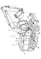
- the hydraulic excavator 1 is a wheel-type hydraulic excavator provided with a self-propellable wheel-type lower traveling body 2 having left and right front wheels 2A and left and right rear wheels 2B.
- the hydraulic excavator 1 includes an upper swivel body 3 mounted on the lower traveling body 2 so as to be swivelable, and a working device 4 provided on the front side of the upper swivel body 3 so as to be able to move up and down.
- the swivel frame 5 has a thick bottom plate 5A extending in the front-rear direction and a left vertical plate 5B erected on the bottom plate 5A and extending in the front-rear direction with a predetermined interval in the left-right direction.
- a left side frame (not shown) extending in the front-rear direction and a plurality of overhanging beams (not shown) extending to the right from the bottom plate 5A and the right vertical plate 5C extending in the front-rear direction. It is configured as a support structure including a provided right side frame 5E, a front frame 5F extending in the left-right direction and connecting a bottom plate 5A, a right vertical plate 5C, and a front end portion of the right side frame 5E.
- a working device 4 is attached to the front portion of the left vertical plate 5B and the right vertical plate 5C.
- the right side frame 5E is formed as a tube having a flat upper surface 5E1.
- the lower side of the swivel frame 5 is covered with an undercover 5G (only the front right portion is shown in FIG. 4).
- the undercover 5G is provided with a work window 5G1 that opens the lower side of the urea water tank 20 described later, and a drain hole 5G2 that is located in front of the work window 5G1 and penetrates in the vertical direction.
- the work window 5G1 of the undercover 5G is an opening for pulling out the drain plug 20J when discharging foreign matter (waste liquid) from the urea water tank 20.
- the drain pipe line 12A (including the hose) of the fuel tank 12, which will be described later, is inserted into the drain hole 5G2.
- the counterweight 6 is provided at the rear of the swivel frame 5.
- the counterweight 6 forms a weight that balances the weight with the working device 4.
- the counterweight 6 is formed in a substantially arc shape in which the center of the rear surface protrudes to the rear side.
- the engine 7 is located on the front side of the counterweight 6 and is provided on the turning frame 5.
- the engine 7 is configured as, for example, a diesel engine, and is mounted in a horizontally extending state extending in the left-right direction.
- a hydraulic pump 8 is attached to the right side of the engine 7.
- the hydraulic pump 8 is driven by the engine 7 to discharge the hydraulic oil from the hydraulic oil tank 11, which will be described later, as pressure oil.
- a heat exchange device 9 is provided on the swivel frame 5.
- the heat exchange device 9 is composed of, for example, a radiator for cooling engine cooling water, an oil cooler for cooling hydraulic oil, an intercooler for cooling air sucked by the engine 7, and the like.
- the NOx purification device 10 is located on the right side of the engine 7 and is provided on the exhaust side of the engine 7.
- the NOx purification device 10 removes nitrogen oxides (NOx) in the exhaust gas using urea water (urea aqueous solution) as a reducing agent.
- the NOx purification device 10 includes a urea selective reduction catalyst, an oxidation catalyst, a urea injection valve, and the like in a cylindrical container.
- the urea injection valve is connected to the urea water tank 20 described later via a supply pump and a supply pipe (neither is shown).
- the NOx purification device 10 injects urea water into the exhaust gas by a urea injection valve, and uses ammonia generated from the urea water by a urea selective reduction catalyst to cause a reduction reaction of NOx in the exhaust gas with water. Decomposes into nitrogen. Then, the oxidation catalyst reduces the amount of ammonia in the exhaust gas.
- the hydraulic oil tank 11 is located on the front side of the engine 7 and the hydraulic pump 8 and is provided on the swivel frame 5.
- the hydraulic oil tank 11 is formed as a rectangular parallelepiped container extending in the vertical direction, and stores hydraulic oil supplied to various actuators mounted on the hydraulic excavator 1 inside the container.
- the fuel tank 12 is provided on the swivel frame 5 adjacent to the front side of the hydraulic oil tank 11 located on the front side of the engine 7.
- the fuel tank 12 is formed as a rectangular parallelepiped container extending in the vertical direction, and stores fuel to be supplied to the engine 7 inside the container.
- the fuel tank 12 has a drain pipe line 12A connected to the lowermost part of the bottom surface.
- the drain pipe line 12A extends forward along the right side frame 5E in the storage case 14 described later, and projects to the lower side of the undercover 5G through the drain hole 5G2.
- a drain cock 12B is provided in the middle of the drain pipe line 12A. By operating the drain cock 12B to the open side, foreign matter in the fuel tank 12 can be discharged through the drain pipe line 12A.
- the cab 13 is provided on the left front side of the swivel frame 5.
- the cab 13 is for the operator to board, and is provided with a driver's seat on which the operator sits, a steering wheel for traveling, an operation lever for work, and the like (none of which are shown).
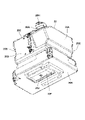
- the storage case 14 is provided on the front side of the swivel frame 5, specifically, on the right front side of the swivel frame 5 which is the front side of the fuel tank 12.
- the inside of the storage case 14 becomes a storage space by using the space on the undercover 5G surrounded by the bottom plate 5A of the swivel frame 5, the right side frame 5E, the front frame 5F, the overhanging beam on the right side, and the like.
- the storage case 14 includes a left face plate 15, a front plate 16, a top plate 17, and a right door 19, which will be described later.
- the storage case 14 uses the front surface of the fuel tank 12 located on the rear side as a rear surface plate for closing the rear side of the storage space. Further, the storage case 14 has an opening 18 that can be opened and closed by the right door 19.
- the left face plate 15 closes the left side of the storage case 14.
- the left face plate 15 extends from the front portion of the fuel tank 12 to the front side so as to face the right vertical plate 5C of the swivel frame 5, and is erected on the bottom plate 5A.
- the portion extending from the front side portion to the upper side portion of the left side plate 15 is inclined upward in a step shape toward the rear side in accordance with the inclined shape of the front side plate 16.
- the front plate 16 closes the front side of the storage case 14.
- the front plate 16 extends diagonally rearward from the upper part of the first block 16A bent in an inverted L shape, the second block 16B continuously provided on the upper part of the first block 16A, and the second block 16B. It is formed by the swash plate portion 16C.
- the left ends of the first block 16A, the second block 16B, and the swash plate portion 16C are attached to the left face plate 15.
- the upper surface of the first block 16A is the second step 28 described later, and the upper surface of the second block 16B is the third step 29 described later.
- the first block 16A is provided with a horn opening 16D which is located closer to the lower side and is composed of a plurality of slits.
- a horn 31, which will be described later, is arranged facing the rear side of the horn opening 16D. Further, the horn opening 16D forms a vent for taking in external air as cooling air in the accommodating case 14 when the hydraulic excavator 1 is traveling.
- the top plate 17 closes the upper side of the storage case 14.
- the top plate 17 is formed so as to extend from the upper portion of the swash plate portion 16C of the front plate 16 to the rear side.
- the left end of the top plate 17 is attached to the left face plate 15.
- the upper surface plate 17 is arranged at a height equivalent to the upper surface of the fuel tank 12, and the upper surface thereof is the fourth step 30 described later.
- the range surrounded by the upper surface 5E1 of the right side frame 5E of the swivel frame 5, the fuel tank 12, the front plate 16 and the upper surface plate 17 is an opening 18. It has become.
- the opening 18 is formed on the right side of the swivel frame 5 (upper swivel body 3) and is used for replenishment of fuel and urea water, and loading and unloading of consumables and tools.
- the right door 19 covers the opening 18 of the storage case 14 so as to be openable and closable from the right side.
- the right door 19 is, for example, a side surface portion 19A formed in a fan shape centered on the lower end portion on the rear side, and a peripheral edge portion 19B curved toward the front plate 16 and the upper surface plate 17 from the arc portion of the side surface portion 19A. It is formed by.
- the right door 19 has a trailing edge portion of the side surface portion 19A attached to the structure on the swivel frame 5 side so as to be openable / closable (rotatable). Further, an opening / closing knob 19C is provided at a position on the front side of the side surface portion 19A.
- the right door 19 can close the opening 18 of the storage case 14 in the closed state shown in FIG.
- the opening 18 of the storage case 14 can be opened as shown in FIGS. 4 and 5.
- the right door 19 is omitted in FIGS. 4 and 5, a similar opening can be obtained even when the right door 19 is fully opened.
- the urea water tank 20 is provided in the storage case 14.
- the urea water tank 20 stores urea water (urea aqueous solution) supplied to the NOx purification device 10.
- the urea water tank 20 is connected to a urea injection valve (neither shown) of the NOx purification device 10 via a supply pump and a supply pipe.
- the urea water tank 20 is located on the rear side (fuel tank 12 side) in the storage case 14 and is mounted on the undercover 5G of the swivel frame 5. In this state, the work window 5G1 of the undercover 5G is arranged under the urea water tank 20.
- the urea water tank 20 has a front surface portion 20A, a rear surface portion 20B, a left surface portion 20C, a right surface portion 20D, an upper surface portion 20E, and a lower surface portion 20F in a state of being housed in the storage case 14. It is formed as a rectangular parallelepiped closed container equipped with.
- the upper surface portion 20E is provided with a water supply port 20G located at a corner between the front surface portion 20A and the right surface portion 20D.
- a cap 20H is detachably attached to the water supply port 20G.
- the water supply port 20G is for replenishing the urea water in the urea water tank 20, and is formed so as to be tilted to the right side on the opening 18 side of the storage case 14.
- a drain hole (not shown) for discharging foreign matter and a drain plug 20J for closing the drain hole are provided at the lowermost position of the lower surface portion 20F.
- the urea water tank 20 is attached to the undercover 5G via the fixing base 20K.
- the right door 19 is opened to form an opening 18 on the right side of the storage case 14.
- prepare a replenishment tank that stores urea water and attach a nozzle to the filling port.
- the cap 20H of the urea water tank 20 is removed, the nozzle of the replenishment tank is inserted into the water supply port 20G, and the replenishment tank is tilted.
- the urea water in the replenishment tank can be replenished to the urea water tank 20.
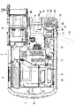
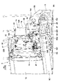
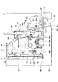
- This urea water supply work is performed from the right side where the opening 18 of the storage case 14 is provided. Therefore, the range required when supplying urea water from the water supply port 20G to the urea water tank 20 in order to perform the water supply work described above is the water supply work space 21 shown by the alternate long and short dash line in FIGS. 5 and 6.
- the water supply work space 21 is located between the fuel tank 12 and the refueling device 22, and is formed on the right side of the water supply port 20G of the urea water tank 20 on the opening 18 side.
- the water supply work space 21 is a rectangular parallelepiped space having a larger space than the cap 20H in the front-rear direction and the vertical direction around the water supply port 20G of the urea water tank 20, and the opening 18 is on the right side. It has reached (right side frame 5E). As a result, when the right door 19 is open, the urea water can be replenished to the urea water tank 20 from the right side of the upper swirl body 3 through the water supply work space 21.
- the refueling device 22 is provided in the storage case 14 in a state of being connected to the fuel tank 12.
- the refueling device 22 replenishes the fuel tank 12 with the fuel stored in the drum can 23, which will be described later, as an external fuel storage source.
- the refueling device 22 includes a fuel supply pump, a fuel filter, and the like. Further, the refueling device 22 includes a fuel suction port 22A for sucking fuel from the outside and a refueling pipeline 22B for supplying the fuel discharged from the fuel supply pump to the fuel tank 12. Most of the refueling device 22 except for the refueling pipeline 22B is arranged in front of the urea water tank 20.
- the fuel suction port 22A constitutes an inlet portion for sucking fuel toward the fuel supply pump.
- the fuel suction port 22A for example, one of the one-touch joints called a quick coupling is used.
- the fuel suction port 22A formed as a joint is provided with a check valve (not shown) inside the fuel suction port 22A to prevent fuel from flowing out (backflow) except during refueling work.
- the fuel suction port 22A is arranged on the frontmost side of the refueling device 22 and has a sufficient distance from the water supply port 20G of the urea water tank 20.
- the fuel suction port 22A is formed toward the right side of the storage case 14 on the opening 18 side.
- the hose 24 extending from the drum can 23, which will be described later, can be easily attached to and detached from the right side of the fuel suction port 22A.
- the right door 19 is opened to form an opening 18 on the right side of the storage case 14, as in the case of supplying urea water.
- a drum 23 as a representative example of an external fuel storage source is prepared, one end of the fuel supply hose 24 is inserted into the drum can 23, and the other end of the hose 24 is connected to the fuel suction port 22A of the refueling device 22. ..
- the operation switch of the refueling device 22 is operated to drive the fuel supply pump.
- the fuel in the drum can 23 can be replenished to the fuel tank 12 via the hose 24 and the refueling device 22.
- This fuel refueling work is performed from the right side where the opening 18 of the storage case 14 is provided. Therefore, the range required when attaching / detaching the hose 24 to / from the fuel suction port 22A in order to perform the above-mentioned refueling work is the refueling work space 25 shown by the alternate long and short dash line in FIGS. 5 and 6.
- the refueling work space 25 is formed on the front side of the water supply work space 21, that is, on the right side of the fuel suction port 22A of the refueling device 22 located between the urea water tank 20 and the front step 26 and on the opening 18 side. ing.
- the refueling work space 25 has a large interval in the front-rear direction and the vertical direction around the fuel suction port 22A of the refueling device 22, for example, the arm holding the hose 24 does not interfere with the surroundings, and the hose. It is a rectangular parallelepiped space in which the 24 can be easily attached and detached, and the right side reaches the opening 18 (right side frame 5E). As a result, when the right door 19 is open, the hose 24 can be connected to the fuel suction port 22A of the refueling device 22 from the right side of the upper swivel body 3 through the refueling work space 25, and the fuel is refueled by the refueling device 22. It is possible to refuel the tank 12.
- the drain cock 12B of the fuel tank 12 is operated with the right door 19 open to bring the drain pipe line 12A into a communicating state.
- the foreign matter in the fuel tank 12 can be discharged together with a small amount of fuel through the drain pipe line 12A.
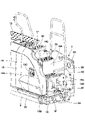
- the front step 26 is provided on the front portion of the swivel frame 5.
- the front step 26 is provided so as to extend forward to the front portion of the front frame 5F of the swivel frame 5.
- the front step 26 constitutes a first step in which the foot is first put on when going up to the upper swivel body 3.
- the front step 26 is arranged at a position lower than the water supply port 20G of the urea water tank 20 and the fuel suction port 22A of the refueling device 22.
- the range in which the foot is put on the front step 26 is the footrest range 27 shown by the alternate long and short dash line in FIG.
- the footrest range 27 is located on the front side of the refueling work space 25.
- the water supply port 20G of the urea water tank 20, the fuel suction port 22A of the refueling device 22, and the front step 26 are arranged side by side in the front-rear direction of the swivel frame 5.
- the required refueling work space 25 and the front step 26 (footrest range 27) arranged at a position lower than the water supply port 20G and the fuel suction port 22A are partitioned and arranged in a plan view.
- the water supply work space 21, the refueling work space 25, and the front step 26 are arranged side by side in the front-rear direction of the swivel frame 5 without overlapping each other.
- the second step 28 is provided on the upper surface of the first block 16A forming the front plate 16 of the storage case 14.
- the third step 29 is provided on the upper surface of the second block 16B.
- the fourth step 30 is provided on the upper surface of the upper surface plate 17 of the storage case 14.
- the horn 31 is provided in the storage case 14, specifically, in the first block 16A of the front plate 16.
- the horn 31 is arranged behind the horn opening 16D formed in the first block 16A.
- the horn 31 emits an alarm sound to call attention to the surroundings.
- the wheel-type hydraulic excavator 1 has the above-mentioned configuration, and its operation will be described next.
- the operator gets on the cab 13 and sits in the driver's seat to operate the engine 7.
- the traveling handle or the like arranged in the cab 13 the lower traveling body 2 can be driven to move the hydraulic excavator 1 forward or backward.
- the operation lever for work it is possible to perform excavation work of earth and sand using the work device 4 while turning the upper swivel body 3.
- nitrogen oxides which are harmful substances
- the NOx purification device 10 injects urea water into the exhaust gas from the urea injection valve to generate ammonia.
- the amount of nitrogen oxides discharged can be reduced by reducing the nitrogen oxides to water and nitrogen and discharging the nitrogen oxides to the outside through the oxidation catalyst.
- the front step 26, the second step 28, the third step 29, and the fourth step 30, which are the first steps, are sequentially put on the foot. , Can go up to the upper swivel body 3.
- each of the water supply port 20G for replenishing urea water in the urea water tank 20 and the fuel suction port 22A for attaching and detaching the fuel supply hose 24 in the refueling device 22. Is provided toward the opening 18 side of the storage case 14.
- the water supply port 20G of the urea water tank 20 and the fuel suction port 22A of the refueling device 22 can be easily accessed through the opening 18.
- the replenishment work can be easily performed and the workability can be improved.
- the water supply port 20G, the fuel suction port 22A, and the front step 26 are arranged side by side in the front-rear direction of the swivel frame 5. As a result, the water supply port 20G, the fuel suction port 22A, and the front step 26 can be reliably separated from each other, and interference during work (during operation) can be prevented.
- the opening 18 of the storage case 14 is formed on the right side of the swivel frame 5. Further, the right door 19 opens and closes the opening 18. Further, the water supply work space 21 required when supplying urea water from the water supply port 20G to the urea water tank 20 is formed on the right side of the water supply port 20G of the urea water tank 20 on the opening 18 side. On the other hand, the refueling work space 25 required when attaching / detaching the hose 24 to / from the fuel suction port 22A is formed on the right side of the fuel suction port 22A of the refueling device 22 on the opening 18 side. As a result, by opening the right door 19, it is possible to perform the urea water replenishment work for the urea water tank 20 housed in the storage case 14 and the fuel replenishment work for the fuel tank 12 using the refueling device 22. can.
- the water supply work space 21 required for replenishing urea water, the refueling work space 25 required for refueling, and the previous step 26 are distinguished without overlapping, urea water or Even if the fuel overflows or splatters, it can be prevented from hitting the previous step 26. As a result, it is possible to omit the work of wiping off the urea water and the fuel applied to the previous step 26 after the replenishment work.
- a drain cock 12B for opening and closing the drain pipe line 12A of the fuel tank 12 is provided in the storage case 14.
- the urea water tank 20 provided in the storage case 14 allows the drain plug 20J to be attached and detached from the lower side of the undercover 5G. Therefore, the work of discharging the foreign matter in the fuel tank 12 and the work of discharging the foreign matter in the urea water tank 20 can be easily performed at the same time.
- the urea water tank 20 is arranged on the rear side in the storage case 14 and the refueling device 22 is arranged on the front side is described as an example.
- the present invention is not limited to this, and the urea water tank 20 may be arranged on the front side in the storage case 14, and the refueling device 22 may be arranged on the rear side.
- the hydraulic excavator 1 provided with the wheel-type lower traveling body 2 has been described as an example.
- the present invention is not limited to this, and may be applied to a hydraulic excavator provided with a crawler type lower traveling body.
Landscapes
- Engineering & Computer Science (AREA)
- Mining & Mineral Resources (AREA)
- Civil Engineering (AREA)
- General Engineering & Computer Science (AREA)
- Structural Engineering (AREA)
- Mechanical Engineering (AREA)
- Exhaust Gas After Treatment (AREA)
- Component Parts Of Construction Machinery (AREA)
Priority Applications (1)
| Application Number | Priority Date | Filing Date | Title |
|---|---|---|---|
| JP2022552024A JP7339453B2 (ja) | 2020-09-28 | 2021-09-22 | 建設機械 |
Applications Claiming Priority (2)
| Application Number | Priority Date | Filing Date | Title |
|---|---|---|---|
| JP2020-162127 | 2020-09-28 | ||
| JP2020162127 | 2020-09-28 |
Publications (1)
| Publication Number | Publication Date |
|---|---|
| WO2022065351A1 true WO2022065351A1 (ja) | 2022-03-31 |
Family
ID=80845522
Family Applications (1)
| Application Number | Title | Priority Date | Filing Date |
|---|---|---|---|
| PCT/JP2021/034749 Ceased WO2022065351A1 (ja) | 2020-09-28 | 2021-09-22 | 建設機械 |
Country Status (2)
| Country | Link |
|---|---|
| JP (1) | JP7339453B2 (cg-RX-API-DMAC7.html) |
| WO (1) | WO2022065351A1 (cg-RX-API-DMAC7.html) |
Citations (8)
| Publication number | Priority date | Publication date | Assignee | Title |
|---|---|---|---|---|
| JP2011064132A (ja) * | 2009-09-17 | 2011-03-31 | Kobelco Contstruction Machinery Ltd | 建設機械 |
| JP2013002082A (ja) * | 2011-06-14 | 2013-01-07 | Hitachi Constr Mach Co Ltd | 建設機械 |
| US20130292386A1 (en) * | 2012-05-01 | 2013-11-07 | Aaron S. Klauer | Diesel exhaust fluid and fuel fill system |
| WO2014192174A1 (ja) * | 2013-09-25 | 2014-12-04 | 株式会社小松製作所 | モータグレーダ |
| JP2016223242A (ja) * | 2015-06-03 | 2016-12-28 | 日立建機株式会社 | 建設機械 |
| JP2017166224A (ja) * | 2016-03-16 | 2017-09-21 | ヤンマー株式会社 | 作業車 |
| JP2017179797A (ja) * | 2016-03-29 | 2017-10-05 | 株式会社Kcm | 作業機械 |
| JP2019056296A (ja) * | 2018-11-21 | 2019-04-11 | 株式会社クボタ | 作業機 |
-
2021
- 2021-09-22 WO PCT/JP2021/034749 patent/WO2022065351A1/ja not_active Ceased
- 2021-09-22 JP JP2022552024A patent/JP7339453B2/ja active Active
Patent Citations (8)
| Publication number | Priority date | Publication date | Assignee | Title |
|---|---|---|---|---|
| JP2011064132A (ja) * | 2009-09-17 | 2011-03-31 | Kobelco Contstruction Machinery Ltd | 建設機械 |
| JP2013002082A (ja) * | 2011-06-14 | 2013-01-07 | Hitachi Constr Mach Co Ltd | 建設機械 |
| US20130292386A1 (en) * | 2012-05-01 | 2013-11-07 | Aaron S. Klauer | Diesel exhaust fluid and fuel fill system |
| WO2014192174A1 (ja) * | 2013-09-25 | 2014-12-04 | 株式会社小松製作所 | モータグレーダ |
| JP2016223242A (ja) * | 2015-06-03 | 2016-12-28 | 日立建機株式会社 | 建設機械 |
| JP2017166224A (ja) * | 2016-03-16 | 2017-09-21 | ヤンマー株式会社 | 作業車 |
| JP2017179797A (ja) * | 2016-03-29 | 2017-10-05 | 株式会社Kcm | 作業機械 |
| JP2019056296A (ja) * | 2018-11-21 | 2019-04-11 | 株式会社クボタ | 作業機 |
Also Published As
| Publication number | Publication date |
|---|---|
| JPWO2022065351A1 (cg-RX-API-DMAC7.html) | 2022-03-31 |
| JP7339453B2 (ja) | 2023-09-05 |
Similar Documents
| Publication | Publication Date | Title |
|---|---|---|
| US10975549B2 (en) | Construction machine | |
| KR101628798B1 (ko) | 환원제 탱크 및 작업 차량 | |
| JP5949793B2 (ja) | 建設機械 | |
| JP4515232B2 (ja) | 旋回作業機 | |
| JP5254821B2 (ja) | 旋回作業機 | |
| JP5438981B2 (ja) | 旋回作業機 | |
| JP2002266377A (ja) | 建設機械における燃料供給装置 | |
| JP3730420B2 (ja) | 旋回式建設機械 | |
| JP5579678B2 (ja) | 建設機械 | |
| JP7339453B2 (ja) | 建設機械 | |
| JP2018162647A (ja) | 建設機械 | |
| CN108025638A (zh) | 储箱以及储箱的制造方法 | |
| JP5631835B2 (ja) | 建設機械 | |
| JP3691767B2 (ja) | 旋回作業機のボンネット支持構造 | |
| JP7009607B2 (ja) | 作業機 | |
| JP2001271375A (ja) | 旋回作業機 | |
| JP7495869B2 (ja) | 建設機械 | |
| JP6510892B2 (ja) | 建設機械 | |
| JP7074631B2 (ja) | 建設機械 | |
| JP6091993B2 (ja) | ショベル | |
| US20260092429A1 (en) | Work machine | |
| JP2026017138A (ja) | 建設機械 | |
| JP2005264557A (ja) | 作業機械 | |
| JP2025047810A (ja) | 作業機械 | |
| JP2024143616A (ja) | 作業車両 |
Legal Events
| Date | Code | Title | Description |
|---|---|---|---|
| 121 | Ep: the epo has been informed by wipo that ep was designated in this application |
Ref document number: 21872480 Country of ref document: EP Kind code of ref document: A1 |
|
| ENP | Entry into the national phase |
Ref document number: 2022552024 Country of ref document: JP Kind code of ref document: A |
|
| NENP | Non-entry into the national phase |
Ref country code: DE |
|
| 122 | Ep: pct application non-entry in european phase |
Ref document number: 21872480 Country of ref document: EP Kind code of ref document: A1 |