WO2022059710A1 - 欠陥検査装置 - Google Patents
欠陥検査装置 Download PDFInfo
- Publication number
- WO2022059710A1 WO2022059710A1 PCT/JP2021/033951 JP2021033951W WO2022059710A1 WO 2022059710 A1 WO2022059710 A1 WO 2022059710A1 JP 2021033951 W JP2021033951 W JP 2021033951W WO 2022059710 A1 WO2022059710 A1 WO 2022059710A1
- Authority
- WO
- WIPO (PCT)
- Prior art keywords
- image
- inspection
- marking
- control unit
- defect
- Prior art date
- Legal status (The legal status is an assumption and is not a legal conclusion. Google has not performed a legal analysis and makes no representation as to the accuracy of the status listed.)
- Ceased
Links
Images


Classifications
-
- G—PHYSICS
- G06—COMPUTING OR CALCULATING; COUNTING
- G06T—IMAGE DATA PROCESSING OR GENERATION, IN GENERAL
- G06T7/00—Image analysis
- G06T7/0002—Inspection of images, e.g. flaw detection
- G06T7/0004—Industrial image inspection
-
- G—PHYSICS
- G01—MEASURING; TESTING
- G01N—INVESTIGATING OR ANALYSING MATERIALS BY DETERMINING THEIR CHEMICAL OR PHYSICAL PROPERTIES
- G01N21/00—Investigating or analysing materials by the use of optical means, i.e. using sub-millimetre waves, infrared, visible or ultraviolet light
- G01N21/01—Arrangements or apparatus for facilitating the optical investigation
-
- G—PHYSICS
- G01—MEASURING; TESTING
- G01N—INVESTIGATING OR ANALYSING MATERIALS BY DETERMINING THEIR CHEMICAL OR PHYSICAL PROPERTIES
- G01N21/00—Investigating or analysing materials by the use of optical means, i.e. using sub-millimetre waves, infrared, visible or ultraviolet light
- G01N21/17—Systems in which incident light is modified in accordance with the properties of the material investigated
- G01N21/41—Refractivity; Phase-affecting properties, e.g. optical path length
- G01N21/45—Refractivity; Phase-affecting properties, e.g. optical path length using interferometric methods; using Schlieren methods
-
- G—PHYSICS
- G01—MEASURING; TESTING
- G01N—INVESTIGATING OR ANALYSING MATERIALS BY DETERMINING THEIR CHEMICAL OR PHYSICAL PROPERTIES
- G01N21/00—Investigating or analysing materials by the use of optical means, i.e. using sub-millimetre waves, infrared, visible or ultraviolet light
- G01N21/84—Systems specially adapted for particular applications
- G01N21/88—Investigating the presence of flaws or contamination
-
- G—PHYSICS
- G01—MEASURING; TESTING
- G01N—INVESTIGATING OR ANALYSING MATERIALS BY DETERMINING THEIR CHEMICAL OR PHYSICAL PROPERTIES
- G01N29/00—Investigating or analysing materials by the use of ultrasonic, sonic or infrasonic waves; Visualisation of the interior of objects by transmitting ultrasonic or sonic waves through the object
- G01N29/04—Analysing solids
- G01N29/06—Visualisation of the interior, e.g. acoustic microscopy
-
- G—PHYSICS
- G01—MEASURING; TESTING
- G01N—INVESTIGATING OR ANALYSING MATERIALS BY DETERMINING THEIR CHEMICAL OR PHYSICAL PROPERTIES
- G01N2201/00—Features of devices classified in G01N21/00
- G01N2201/06—Illumination; Optics
- G01N2201/061—Sources
- G01N2201/06113—Coherent sources; lasers
-
- G—PHYSICS
- G06—COMPUTING OR CALCULATING; COUNTING
- G06T—IMAGE DATA PROCESSING OR GENERATION, IN GENERAL
- G06T2207/00—Indexing scheme for image analysis or image enhancement
- G06T2207/20—Special algorithmic details
- G06T2207/20212—Image combination
- G06T2207/20221—Image fusion; Image merging
-
- G—PHYSICS
- G06—COMPUTING OR CALCULATING; COUNTING
- G06T—IMAGE DATA PROCESSING OR GENERATION, IN GENERAL
- G06T2207/00—Indexing scheme for image analysis or image enhancement
- G06T2207/30—Subject of image; Context of image processing
- G06T2207/30108—Industrial image inspection
- G06T2207/30136—Metal
-
- G—PHYSICS
- G06—COMPUTING OR CALCULATING; COUNTING
- G06T—IMAGE DATA PROCESSING OR GENERATION, IN GENERAL
- G06T2207/00—Indexing scheme for image analysis or image enhancement
- G06T2207/30—Subject of image; Context of image processing
- G06T2207/30204—Marker
Definitions
- the present invention relates to a defect inspection device, and more particularly to a defect inspection device including an image pickup unit.
- a defect inspection device provided with an image pickup unit is known.
- Such a defect inspection device is disclosed in, for example, Japanese Patent Application Laid-Open No. 2017-219318.
- the defect inspection apparatus described in JP-A-2017-219318 includes an excitation unit that excites an elastic wave to the object to be inspected, an illumination unit that illuminates the measurement area on the surface of the object to be inspected with a strobe, and an excitation (vibration). It comprises an interferometer including an image sensor that detects light that is reflected by the object to be inspected and interferes with each other. Further, the control unit provided in the defect inspection device performs data processing based on the detection signals obtained from each detection element of the image sensor. By performing known image processing on the image obtained as a result of this data processing, defects on the surface of the object to be inspected are detected.
- a portion (for example, a step) that is not a defect of the object to be inspected is obtained as a result of data processing in a shape similar to the defect. May be displayed on the image.
- the user looks at the image obtained as a result of the data processing and determines whether or not the displayed image is a defect between the displayed image and the region of interest (for example, a region where the defect is likely to occur). It is necessary to distinguish from the positional relationship. For example, the user determines that the displayed image is defective based on the presence of the displayed image in the region of interest.
- the position of the region of interest in the image obtained as a result of data processing needs to be read by the user himself / herself, the position of the region of interest read may differ from each other depending on the user.
- the images that are discriminated (identified) as defects by the user are different from each other, so that the inspection result differs depending on the user. Therefore, there is a demand for a defect inspection device capable of suppressing differences in inspection results depending on the user.
- the present invention has been made to solve the above-mentioned problems, and one object of the present invention is to provide a defect inspection device capable of suppressing a difference in inspection results depending on a user. That is.
- the defect inspection apparatus has an image pickup unit that captures an image of an inspection target, a display section that displays an image based on the image captured by the image pickup section, and a display section. It includes a control unit that accepts the setting of marking on a predetermined region of interest on the image, and the control unit inspects the defect to be inspected based on the image captured by the image pickup unit and displays it on the display unit. It is configured to superimpose the marking image on a position corresponding to a predetermined region of interest in the image of the inspection result.
- the control unit accepts the setting of marking on the predetermined region of interest on the image displayed on the display unit, and at the same time, the inspection result displayed on the display unit is displayed. It is configured to superimpose the marking image on a position corresponding to a predetermined region of interest of the image. As a result, the position where the marking is displayed in the image of the inspection result is the same even if the user performing the inspection is different. As a result, by discriminating the defect based on the position of the marking displayed on the image of the inspection result, it is possible to suppress the difference in the inspection result depending on the user.
- the defect inspection device 100 is an apparatus for inspecting the defects of the inspection target 7.
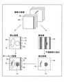
- the defect inspection device 100 displays the oscillator 1, the laser illumination 2, the speckle sharing interferometer 3, the control unit 4, and the signal generator 5.
- a unit 6 and a storage unit 8 are provided. Note that FIG. 1 shows that the control unit 4, the display unit 6, and the storage unit 8 are provided separately from each other, but the present invention is not limited to this.
- the control unit 4, the display unit 6, and the storage unit 8 may be provided in a common terminal.
- the oscillator 1 and the speckle-sharing interferometer 3 are examples of the "exciting unit” and the "interfering unit” in the claims, respectively.
- the oscillator 1 and the laser illumination 2 are connected to the signal generator 5 via a cable.
- the oscillator 1 excites vibration (sound wave vibration) in the inspection target 7. Specifically, the oscillator 1 is arranged so as to be in contact with the inspection target 7, converts the AC electric signal from the signal generator 5 into mechanical vibration, and excites the vibration (sonic vibration) to the inspection target 7. .. The oscillator 1 excites ultrasonic vibration to the inspection target 7.
- the laser illumination 2 irradiates the inspection target 7 with a laser beam.
- the laser illumination 2 includes a laser light source (not shown) and an illumination light lens.
- the illumination light lens spreads the laser beam emitted from the laser light source over the entire measurement area on the surface of the inspection target 7 and irradiates it. Further, the laser illumination 2 irradiates the laser beam at a predetermined timing based on the electric signal from the signal generator 5. That is, the laser illumination 2 irradiates the inspection target 7 with the laser beam in response to the vibration caused by the vibrator 1.
- the speckle-sharing interferometer 3 is configured to interfere with the reflected light of the laser beam arriving from different positions of the inspection target 7 excited by the vibrator 1. Further, the speckle sharing interferometer 3 includes a beam splitter 31, a phase shifter 32, a first reflecting mirror 331, a second reflecting mirror 332, a condenser lens 34, and an image sensor 35.
- the image sensor 35 is an example of the "imaging unit" in the claims.
- the beam splitter 31 includes a half mirror. Further, the beam splitter 31 is arranged at a position where the laser beam reflected on the surface of the inspection target 7 is incident. Further, the beam splitter 31 reflects the incident laser light toward the phase shifter 32 and transmits it to the second reflecting mirror 332 side. Further, the beam splitter 31 reflects the laser light reflected by the second reflecting mirror 332 and incident on the condenser lens 34 side, and the laser light reflected by the first reflecting mirror 331 and incident on the condenser lens 34 side. To be transparent to.
- the first reflecting mirror 331 is arranged so as to have an angle of 45 degrees with respect to the reflecting surface of the beam splitter 31 on the optical path of the laser beam reflected by the beam splitter 31.
- the first reflecting mirror 331 reflects the laser beam reflected by the beam splitter 31 and incident on the beam splitter 31 side.
- the second reflecting mirror 332 is arranged on the optical path of the laser beam passing through the beam splitter 31 so as to be slightly inclined from an angle of 45 degrees with respect to the reflecting surface of the beam splitter 31.
- the second reflecting mirror 332 reflects the laser beam reflected by the beam splitter 31 and incident on the beam splitter 31 side.
- the phase shifter 32 is arranged between the beam splitter 31 and the first reflecting mirror 331, and the phase of the transmitted laser beam is changed (shifted) by the control of the control unit 4. Specifically, the phase shifter 32 is configured to change the optical path length of the transmitted laser beam.
- the image sensor 35 has a large number of detection elements, and is reflected by the beam splitter 31 and then reflected by the first reflecting mirror 331 to pass through the beam splitter 31 (straight line in FIG. 1) and through the beam splitter 31. After that, it is arranged on the optical path of the laser beam (broken line in FIG. 1) reflected by the second reflecting mirror 332 and reflected by the beam splitter 31.
- the image sensor 35 includes, for example, a CMOS image sensor, a CCD image sensor, or the like.
- the image sensor 35 is configured to capture an incident laser beam. Further, the image sensor 35 is configured to capture the reflected light interfered by the speckle-sharing interferometer 3. As a result, the inspection target 7 is imaged by the image sensor 35.
- the condenser lens 34 is arranged between the beam splitter 31 and the image sensor 35, and the laser beam transmitted through the beam splitter 31 (straight line in FIG. 1) and the laser beam reflected by the beam splitter 31 (broken line in FIG. 1). ) And condensing.
- the laser beam (straight line in FIG. 1) reflected by the position 741 on the surface of the inspection target 7 and the first reflecting mirror 331 and the laser reflected by the position 742 and the second reflecting mirror 332 on the surface of the inspection target 7.
- the light (broken line in FIG. 1) interferes with each other and is incident on the same location of the image sensor 35.
- Positions 741 and 742 are positions separated from each other by a small distance.
- the reflected light of the laser beam arriving from different positions in each region of the inspection target 7 is guided by the speckle sharing interferometer 3 and incident on the image sensor 35, respectively. do.
- the control unit 4 operates the phase shifter 32 arranged in the speckle sharing interferometer 3 with an actuator (not shown) to change the phase of the transmitted laser beam. As a result, the phase difference between the laser beam reflected at the position 741 and the laser beam reflected at the position 742 changes.
- Each detection element of the image sensor 35 detects the intensity of the interference light in which these two laser beams interfere with each other.
- the control unit 4 controls the vibration of the oscillator 1 and the timing of irradiation of the laser beam of the laser illumination 2 via the signal generator 5, and captures an image while changing the phase shift amount.
- a total of 37 images are taken, including 5 images before and after each phase shift amount (0, ⁇ / 4, ⁇ / 2, 3 ⁇ / 4) when the light is turned off.
- ⁇ is the wavelength of the laser beam.
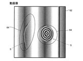
- the control unit 4 processes the detection signal from each detection element according to the following procedure, and acquires a moving image 62 (see FIG. 2) showing the state of vibration.
- the control unit 4 measures the spatial distribution of the periodically changing physical quantity generated by the propagation of the vibration of the inspection target 7 based on the interfered reflected light captured by the image sensor 35.
- the control unit 4 generates a moving image 62 (spatial distribution image) relating to the propagation of the vibration of the inspection target 7 based on the interfered reflected light captured by the image sensor 35.
- B is a complex amplitude and is expressed as in the following equation (3).
- B Aexp (i ⁇ ): Complex amplitude ... (3)
- the control unit 4 displays a moving image 62 (30 to 60 frames) of the optical phase change at each phase time ⁇ (0 ⁇ ⁇ ⁇ 2 ⁇ ) of the vibration from the approximate expression obtained by removing the constant term C from the equation (2). ) Is output.
- a spatial filter is appropriately applied to the complex amplitude B for noise reduction.
- the phase shift amount and the laser irradiation timing step ( ⁇ / 4 and T / 8, respectively in the above example, where T is the vibration cycle) are not limited to this. In this case, the calculation formula is different from the above formulas (1) to (3).
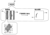
- the control unit 4 applies a spatial filter and detects the discontinuous region of the vibration state as the defect portion 73 of the inspection target 7 from the above moving image 62. That is, the control unit 4 extracts the discontinuous portion of the vibration based on the spatial distribution of the physical quantity. Specifically, the control unit 4 acquires an extracted image 63 from which the discontinuous portion of the vibration is extracted from the moving image 62.
- the control unit 4 acquires the still image 61 and the moving image 62 based on the interfered reflected light captured by the image sensor 35.
- the still image 61 is an image that displays the brightness and darkness of the light of the inspection target 7.
- the moving image 62 is an image displaying the phase fluctuation due to the brightness and darkness of light and the ultrasonic vibration of the inspection target 7.
- the moving image 62 is an example of the “image showing the vibration state of the inspection target” in the claims.
- the control unit 4 is configured to acquire one still image 61 based on a plurality of images 60 (still images) captured by the image sensor 35. Specifically, the control unit 4 is configured to acquire one still image 61 by adding and averaging a plurality of images 60 captured in order to generate a moving image 62 relating to the propagation of vibration of the inspection target 7. ing. In this still image 61, it is possible to confirm the changed portion 75 in the structure of the inspection target 7. Although the moving image 62 relating to the propagation of the vibration of the inspection target 7 can confirm the vibration, it is difficult to visually confirm the changed portion in the structure of the inspection target 7.
- control unit 4 is configured to accept the setting of the marking 64 on the still image 61.
- the marking 64 includes figures and characters. The control of the control unit 4 regarding the marking 64 will be described in detail later.
- control unit 4 is configured to perform control to emphasize and superimpose the discontinuous portion of the vibration extracted from the moving image 62 on one still image 61 acquired by addition averaging. ..
- control unit 4 is configured to generate (acquire) an overlay image 65 in which the discontinuous portion of the vibration extracted from the moving image 62 is superimposed on the still image 61 as an image of the inspection result.
- the overlay image 65 is an example of the "image of the inspection result based on the image showing the vibration state of the inspection target" in the claims.
- the display unit 6 displays the still image 61, the moving image 62, and the overlay image 65.
- the display unit 6 includes a liquid crystal display, an organic EL display, and the like.
- the still image 61 and the moving image 62 are examples of the "image based on the image captured by the image pickup unit" in the claims.
- the inspection target 7 is a painted steel sheet in which a coating film 72 (see FIG. 1) is coated on the surface of the steel sheet 71.
- the defective portion 73 includes cracks, peeling, and floating under the coating film. Further, when the inspection target 7 is a member for joining different materials, the defective portion 73 includes a defective joining portion.
- defect display processing Next, with reference to FIG. 3, the defect display process by the defect inspection device 100 of the first embodiment will be described with reference to the flowchart.
- the defect display process is performed by the control unit 4.
- step 101 of FIG. 3 vibration is applied from the oscillator 1 to the inspection target 7. As a result, vibration is excited to the inspection target 7.
- step 102 the laser beam from the laser illumination 2 irradiates the measurement area of the inspection target 7.
- step 103 interference data is acquired while changing the shift amount of the phase shifter 32. That is, a plurality of images 60 (see FIG. 2) having different phases and interfering with each other are imaged. Specifically, the phase shifter 32 of the speckle sharing interferometer 3 is operated so that the phase of the laser beam changes by ⁇ / 4, and the intensity of the interference light of the laser beam in each phase is determined by the image sensor 35. Is detected (imaging).
- step 104 the vibration application from the oscillator 1 to the inspection target 7 is completed.
- step 105 one still image 61 (see FIG. 2) is acquired (generated) based on the plurality of images 60 acquired in step 103.
- step 106 the control unit 4 accepts the setting of the marking 64 on the predetermined area of interest S (for example, a place where a defect is likely to occur) on the still image 61 displayed on the display unit 6. Specifically, when the user inputs the marking 64 on the still image 61, the input marking 64 is set (initial setting). That is, the data of the marking 64 input on the still image 61 is stored in the storage unit 8 (see FIG. 1).
- step 107 the control unit 4 inspects the defect of the inspection target 7 based on the image 60 captured by the image sensor 35. Specifically, first, the control unit 4 acquires (generates) a moving image 62 (see FIG. 2) from a plurality of images 60. Next, the control unit 4 extracts the discontinuous portion of the vibration from the moving image 62 (see FIG. 2). Then, the control unit 4 superimposes the discontinuous portion of the vibration extracted from the moving image 62 (extracted image 63: see FIG. 2) on the still image 61 acquired in step 105 (see FIG. 2). ).
- the control unit 4 has an image of the inspection result before the image of the marking 64 is superimposed (the marking 64 is superimposed) separately from the data of the marking 64 set in the later step 108. It is configured to store the data of the overlay image 65) before it is created in the storage unit 8. Further, for images other than the above, the image data obtained in the inspection process can be stored in the storage unit 8. For example, the data of the moving image 62, the data of the still image 61, the data of the extracted image 63, the data of each of the plurality of images 60, and the like can be stored in the storage unit 8. Further, the storage unit 8 also stores an image (see FIG. 5) in which the image of the marking 64 is superimposed on the image of the inspection result.
- the control unit 4 displays the overlay image 65 acquired in step 107 on the display unit 6.
- the control unit 4 has a marking 64 at a position corresponding to a predetermined region of interest S (see FIG. 2) of the overlay image 65 (image of the inspection result) displayed on the display unit 6. It is configured to superimpose images. That is, in the overlay image 65, the position (coordinates) on the inspection target 7 where the marking 64 is arranged is controlled to be the same as the position (coordinates) on the inspection target 7 where the marking 64 is arranged in the still image 61. Will be done. Further, the control unit 4 displays the overlay image 65 on which the image of the marking 64 is superimposed on the display unit 6 by using the data of the overlay image 65 and the data of the image of the marking 64 stored in the storage unit 8. It is configured in.
- the control unit 4 is configured to superimpose the image of the marking 64 on the position corresponding to the predetermined region of interest S of the moving image 62. That is, in the moving image 62, the position (coordinates) on the inspection target 7 where the marking 64 is arranged is controlled to be the same as the position (coordinates) on the inspection target 7 where the marking 64 is arranged in the still image 61. Will be done. Further, the control unit 4 is configured to display the moving image 62 on which the image of the marking 64 is superimposed on the display unit 6 by using the data of the moving image 62 and the data of the marking 64 stored in the storage unit 8. Has been done.
- the defective portion 73 (discontinuous portion) is more likely to be clearly displayed than in the overlay image 65. Therefore, since the marking 64 can be superimposed on the moving image 62 in addition to the overlay image 65, the moving image 62 can be used when it is difficult to discriminate the defective portion 73 in the overlay image 65. Therefore, it is possible to easily identify the defective portion 73.
- control unit 4 is configured to be able to superimpose the ruler 80 (see FIG. 6) on the overlay image 65.
- the ruler 80 may be displayed in the moving image 62 or the extracted image 63.
- step 109 it is determined whether or not the user has corrected (including addition) the data of the marking 64 on the overlay image 65 (moving image 62). For example, as shown in FIG. 5, when the position of the image of the marking 64 and the position of the image of the defective portion 73 are deviated from each other in the overlay image 65 (moving image 62), the data of the marking 64 is corrected (added). Was done by the user. In the example shown in FIG. 5, the position of the marking 64 on the upper right and the position of the defective portion 73 are deviated from each other. Then, in this example, the marking 64 (broken line) surrounding the defective portion 73 is modified (added) so as to be arranged. The example of modifying (adding) the data of the marking 64 is not limited to this.
- control unit 4 accepts the correction (addition) of the marking 64 data on the overlay image 65 (moving image 62), the process proceeds to step 110. If the correction (addition) of the marking 64 data is not accepted on the overlay image 65 (moving image 62) (that is, the user does not make the correction (addition)), the process proceeds to step 111.
- control unit 4 is configured to reflect the correction (addition) of the marking 64 data to the set marking 64 data. Specifically, the correction (addition) is reflected in the data of the marking 64 stored in the storage unit 8.
- control unit 4 changes the color of the corrected (added) marking 64 (broken line marking 64 shown in FIG. 5) to the original marking 64 (in FIG. 5). It is configured to be displayed in a color different from the solid line marking 64) shown.
- step 111 the inspection result is output. Specifically, an image in which the image of the marking 64 is superimposed on the overlay image 65 (moving image 62) is output as data (bitmap file or moving image file). At this time, the data of the image in which the image based on the data of the marking 64 reflecting the correction (addition) in step 110 is superimposed on the overlay image 65 (moving image 62) is output. It should be noted that the image based on the data of the marking 64 before the correction (addition) is reflected may be configured so that the data of the image superimposed on the overlay image 65 (moving image 62) can be output.
- the plurality of images 60 and the like acquired in step 103 are also configured to be individually outputable.
- step 112 the control unit 4 ends the inspection by inputting an instruction to end the inspection from the user or the like. If the inspection is to be continued, the process returns to step 101.
- control unit 4 is configured to repeatedly use the data of the marking 64 stored in the storage unit 8 at each inspection different from each other.
- the marking 64 data set in the first inspection is also reused (reused) in the subsequent inspection (defect display processing).
- the step of initial setting (step 106) of the marking 64 is omitted.
- the control unit 4 sends the storage unit 8 in the first inspection in each of the case where a plurality of inspection targets 7 of the same type are individually inspected and the case where the same inspection target 7 is inspected a plurality of times.
- This inspection is performed with the saved marking 64 data read.
- the control unit 4 is configured to superimpose the image of the read marking 64 on the position corresponding to the predetermined region of interest S of the image of the inspection result (overlay image 65, moving image 62). .. If the marking 64 data has been modified (added) by the previous inspection, the marking 64 data reflects the modification (addition) or before the modification (addition) is reflected. The user can select which of the marking 64 data (ie, the first marking 64 data) is superimposed on the inspection result image.
- the control unit 4 may determine whether or not the marking 64 setting has been completed. With this configuration, it is determined that the marking 64 setting has not been completed in the first inspection, and it is determined that the marking 64 setting has been completed in the second and subsequent inspections. .. Further, the control unit 4 may be configured to notify the user (for example, display the fact on the display unit 6) when it is determined that the setting of the marking 64 is not completed. On the other hand, when the control unit 4 determines that the setting of the marking 64 is completed, the control unit 4 automatically reads the data of the marking 64 stored in the storage unit 8 (without inputting the user's instruction). It may be configured in. In different inspections, the orientation of the inspection target 7 set in the defect inspection device 100, the imaging range, and the like need to be adjusted so as to be the same as each other.
- the control unit 4 inspects the defect of the inspection target 7 based on the image captured by the image sensor 35 (imaging unit), and at the same time, the overlay image displayed on the display unit 6. It is configured to superimpose the image of the marking 64 on the position corresponding to the predetermined region of interest S of 65 (the image of the inspection result). As a result, the position where the marking 64 is displayed in the overlay image 65 is the same even if the user performing the inspection is different. As a result, by discriminating the defect based on the position of the marking 64 displayed on the overlay image 65, it is possible to suppress the difference in the inspection result depending on the user.
- the defect inspection device 100 includes a vibrator 1 (excitation unit) that excites sound wave vibration in the inspection target 7, a laser illumination 2 that irradiates the inspection target 7 with laser light, and vibration. It is provided with a speckle-sharing interferometer 3 (interference unit) that interferes with reflected light of laser light arriving from different positions of the inspection target 7 excited by the child 1. Further, the image sensor 35 (imaging unit) is configured to capture the interfered reflected light. Further, the control unit 4 acquires an image showing the vibration state of the inspection target 7 based on the interfered reflected light captured by the image sensor 35, and the overlay image 65 (inspection result) based on the image showing the vibration state of the inspection target 7.
- the image of the marking 64 is superimposed on the position corresponding to the predetermined region of interest S of the image).
- the brightness of the inspection target 7 irradiated by the laser illumination 2 may be uneven or the like. Due to this, a display similar to a defect may appear in a portion where the amount of light is relatively low. Therefore, when inspecting based on an image showing the vibration state of the inspection target 7, a relatively high skill level is required to discriminate defects. Therefore, by superimposing the image of the marking 64 on the position corresponding to the predetermined region of interest S of the overlay image 65, it is possible to suppress the difference in the inspection result depending on the user in the image showing the vibration state of the inspection target 7. It is especially effective when inspecting based on.
- the control unit 4 has an overlay image 65 (inspection) acquired by using the still image 61 and the moving image 62 based on the image captured by the image sensor 35 (imaging unit).
- the image of the marking 64 is superimposed on the position corresponding to the predetermined region of interest S of the resulting image).
- the defect can be discriminated based on the position of the marking 64 displayed on the overlay image 65 acquired by using the still image 61 and the moving image 62.
- the overlay image 65 to discriminate (identify) the defect, it is possible to prevent the inspection result from being different depending on the user.
- the control unit 4 displays the light and darkness of the light of the inspection target 7 based on the interfered reflected light imaged by the image sensor 35 (imaging unit) 61. And the moving image 62 showing the vibration state of the inspection target 7, and the overlay image 65 in which the discontinuous portion of the vibration extracted from the moving image 62 is superimposed on the still image 61 is acquired as the inspection result image. It is configured to do. Further, the control unit 4 accepts the setting of the marking 64 on the predetermined area of interest S on the still image 61 displayed on the display unit 6, and marks the position corresponding to the predetermined area of interest S of the overlay image 65. It is configured to superimpose 64 images.
- the inspection result differs depending on the user. It can be suppressed.
- control unit 4 is configured to superimpose the image of the marking 64 on the position corresponding to the predetermined region of interest S of the moving image 62. As a result, when the user visually recognizes the moving image 62 to discriminate (identify) the defect, it is possible to prevent the inspection result from being different depending on the user.
- the defect inspection device 100 includes a storage unit 8 for storing the data of the set marking 64.
- the control unit 4 is configured to repeatedly use the data of the marking 64 stored in the storage unit 8 each time the inspection is different from each other. As a result, it is not necessary to set the marking 64 for each inspection different from each other. For example, it is possible to save the trouble of searching for a predetermined region of interest S while referring to a specification or the like each time an inspection is performed. As a result, when performing a plurality of inspections, the time required for the inspection can be shortened.
- the control unit 4 individually inspects a plurality of the same type of inspection objects 7 and the case where the same inspection object 7 is inspected a plurality of times.
- the defect of the inspection target 7 this time is inspected in a state where the data of the marking 64 stored in the storage unit 8 is read, and the predetermined overlay image 65 (image of the inspection result) of this time is inspected.
- the image of the read marking 64 is superimposed on the position corresponding to the region of interest S.
- the marking 64 is set only in the first inspection, the step of setting the marking 64 in the subsequent inspections can be omitted.
- the time required for the inspection can be further shortened.
- the data of the overlay image 65 (image of the inspection result) before the image of the marking 64 is superimposed is stored in the storage unit 8 separately from the data of the marking 64. It is configured as follows. This makes it possible to efficiently handle the image of the marking 64 and the overlay image 65 before the image of the marking 64 is superimposed (for example, each image is individually posted in the report). can.
- the marking 64 data is set. , It is configured to reflect the correction of the data of the marking 64.
- the corrected image of the marking 64 is superimposed on the overlay image 65. It can be superimposed.
- the inspection target area is a part of the imaging range displayed on the display unit 6. It is configured to be limited to.
- the control unit 14 is constant when the image of the marking 64 surrounding a certain range is superimposed on the image for inspection (moving image 62 in the example shown in FIG. 7). It is configured to exclude the area outside the range of the above from the inspection target area and detect (extract) the defect within a certain range. That is, only the discontinuous portion within the range of the marking 64 is displayed (extracted) on the extracted image 63.
- the control unit 14 has a function (inspection range trimming function) of extracting (trimming) only the range to be inspected from the entire imaging range.
- control unit 14 is configured to detect defects based on the degree of brightness of each pixel in the image 60 captured by the image sensor 35.
- control unit 14 is configured to detect defects based on the luminance value of each pixel.
- the control unit 14 has a function (threshold value comparison function) of detecting defects based on a comparison between the brightness value of each pixel (the degree of brightness of each pixel) and the threshold value.
- the control unit 14 has a defect (discontinuous portion) in a portion where the luminance value is equal to or higher than a predetermined threshold value within a certain range (range of marking 64). It is configured to detect as. Specifically, the control unit 14 detects the magnitude of the luminance value of each pixel (detection element) (for example, 6 steps from 0 to 5) within the range of the marking 64. Then, the control unit 14 detects (extracts) a pixel (detection element) having a luminance value equal to or higher than a predetermined threshold value (for example, 3 or more) as a pixel (detection element) having a defect (discontinuous portion). Note that FIG. 7 schematically shows the distribution of the luminance values.
- control unit 14 also has a defect in the entire imaging range displayed on the display unit 6 based on the comparison between the brightness value of each pixel (the degree of brightness of each pixel) and the threshold value. It is possible to detect (extract). That is, the control unit 14 sets the range (inspection range) for detecting (extracting) defects based on the comparison between the brightness value of each pixel (the degree of brightness of each pixel) and the threshold value to be constant with the entire imaging range. It is configured to be switchable within the range of (marking 64 range). Further, the control unit 14 detects (extracts) defects based on a comparison between the brightness value of each pixel (the degree of brightness of each pixel) and the threshold value within each range of the plurality of markings 64. You may go.
- control unit 14 has a function (ratio determination function) of determining the state of the inspection target 7 (pass / fail of the inspection result) based on the ratio of the pixels corresponding to the defects detected in the image 60 captured by the image sensor 35. ).
- the control unit 14 is configured to determine whether or not a defect exists in the inspection range of the inspection target 7 in excess of a preset standard (predetermined ratio).
- the control unit 14 determines the state of the inspection target 7 (pass / fail of the inspection result) based on the ratio of the pixels corresponding to the defects detected within a certain range (the range of the marking 64). It is configured as follows.
- the control unit 14 is detected as a defect in the inspection range extracted (trimmed) from the entire imaging range by the inspection range trimming function (in the inspection range extracted from the entire imaging range). It has a function of determining the state of the inspection target 7 based on the ratio of the pixels corresponding to the location). Specifically, the inspection target is based on the ratio of the number of pixels of the portion (defect location) detected as a defect by the threshold value comparison function to the number of pixels of the inspection range extracted (trimmed) by the inspection range trimming function. It is determined whether the state of 7 is good or bad (pass / fail of the inspection result).
- control unit 14 determines the state of the inspection target 7 based on the ratio of the number of pixels of the defective portion (the portion detected as a defect by the threshold value comparison function) to the total number of pixels of the imaging range. Is possible. That is, in the ratio determination function, the control unit 14 compares the number of pixels with the number of pixels of the defective portion (the portion detected as a defect by the threshold value comparison function) with the total number of pixels in the imaging range and a certain range. It is configured to be switchable to the number of pixels within (the range of marking 64).
- control unit 14 is configured to superimpose information based on the luminance value as the degree of brightness of each pixel in the image 60 captured by the image sensor 35 on the overlay image 65 (image of the inspection result). .. Specifically, as shown in FIG. 8, defect regions 91 and 92 (regions shown by broken lines) based on the degree of brightness (luminance value) of each pixel are superimposed on the image of the inspection result.
- the defect areas 91 and 92 are examples of "information based on the luminance value" in the claims.
- the defect region 91 is a region having a luminance value of 4 or more
- the defect region 92 is a region having a luminance value of 3 or more.
- control unit 14 may visualize the change in the degree of brightness (luminance value) of each pixel by color and superimpose it on the overlay image 65 (image of the inspection result) like a heat map. That is, the change in the degree of brightness (luminance value) of each pixel may be displayed by the change in color (change in color or shading) and superimposed on the overlay image 65 (image of the inspection result). Further, a value (numerical value) based on the luminance value may be superimposed on the overlay image 65 (image of the inspection result). For example, the luminance value (see FIG. 7) of a pixel whose luminance value is equal to or higher than a predetermined threshold value may be superimposed and displayed on the overlay image 65 (inspection result image).
- the control unit 14 is configured to detect defects based on the degree of brightness (luminance value) of each pixel in the image captured by the image sensor 35 (imaging unit). Has been done. As a result, the control unit 14 can automatically detect the defect based on the brightness degree (luminance value) of each pixel in the image captured by the image sensor 35 (imaging unit). As a result, unlike the case where the user visually determines (identifies) the defect, it is possible to suppress the difference in the inspection result depending on the user.
- the control unit 14 states the inspection target 7 based on the ratio of the pixels corresponding to the defects detected in the image captured by the image sensor 35 (imaging unit). Is configured to determine. Thereby, the quality of the state of the inspection target 7 can be obtained from the ratio of defects in the inspection range. Further, when the ratio of defects in the inspection range is high, the user can take measures for the inspection target 7.
- the control unit 14 obtains information based on the luminance value as the brightness degree of each pixel in the image 60 imaged by the image sensor 35 (imaging unit) as the overlay image 65. It is configured to be superimposed on (the image of the inspection result). As a result, the user can visually confirm the information based on the luminance value, so that the change in the luminance value within the inspection range can be easily grasped.
- the inspection outside the range of the marking 64 is omitted, so that the load on the control unit 14 can be reduced.
- control unit 14 determines the brightness of each pixel in the image 60 imaged by the image sensor 35 (imaging unit) within a certain range (range of marking 64). It is configured to detect a portion having a brightness value equal to or higher than a predetermined threshold value as a defect (discontinuous portion). As a result, the defect within the range of the marking 64 can be reliably detected as compared with the case where the defect is visually confirmed by the user.
- the control unit 14 is an inspection target based on the ratio of pixels corresponding to defects (discontinuous portions) detected within a certain range (range of marking 64). It is configured to determine the state of 7. Thereby, the state of the inspection target 7 can be determined based on the ratio of the pixels corresponding to the defect (discontinuous portion) in an arbitrary range within the imaging range. As a result, even if the changed portion 75 in the structure of the inspection target 7 is detected as a defect, the portion (non-defect) that is not desired to be included as a defect in the structure of the inspection target 7 is the inspection target 7. The test result can be excluded from the pass / fail range. Thereby, the state of the inspection target 7 can be determined more accurately.
- the image of the inspection result (overlay image 65, etc.) is displayed only on the display unit 6, but the present invention is not limited to this.
- an image of the inspection result may be projected on the surface of the inspection target 7.
- the defect inspection device 200 includes a projection unit 131 that projects an image of the inspection result (overlay image 65) on which the image of the marking 64 is superimposed on the inspection target 7.
- the projection unit 131 is provided in the speckle sharing interferometer 13 provided in the defect inspection device 200.
- the projection unit 131 may be provided separately from the speckle sharing interferometer 13.
- the speckle-sharing interferometer 13 is an example of the "interference unit" in the claims.
- the projected image 13a of the inspection result image (overlay image 65) is projected on the inspection target 7.
- the positions of the defect portion 73 (particularly, defects that cannot be directly visually recognized such as internal defects) displayed on the display unit 6 and the marking 64 to be inspected 7 in the actual object can be easily grasped based on the projected image 13a. ..
- the projection unit 131 is controlled so that the projected image 13a becomes the actual size.
- the size of the defect may be measured using a three-dimensional measuring instrument.
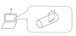
- the defect inspection device 300 includes a three-dimensional measuring instrument 231.
- the three-dimensional measuring instrument 231 is provided in the speckle sharing interferometer 23 provided in the defect inspection device 300.
- the three-dimensional measuring instrument 231 may be provided separately from the speckle sharing interferometer 23.
- the 3D data of the inspection target 17 measured by the 3D measuring instrument 231 is sent to the control unit 44.
- the control unit 44 extracts defects by the method described in the above embodiment. Then, the control unit 44 displays an image (see FIG. 11) in which the image of the defect is superimposed on the three-dimensional image of the inspection target 17 on the display unit 6.
- the control unit 44 is configured to be able to calculate the length L of the defective portion in the three-dimensional image displayed on the display unit 6 based on the acquired three-dimensional data or the like. This makes it possible to easily calculate the size of the defect even when the inspection target has a three-dimensional and complicated shape. Further, since it is not necessary to use a ruler or the like, it is possible to simplify the work of measuring the size of the defect.
- the marking 64 may be set on a plurality of images 60 (at least a part of them).
- the overlay image may be generated by superimposing the image 60 on which the marking 64 is set and the extracted image 63.
- a defect inspection fault detection
- ultrasonic vibration an example of performing a defect inspection (fault detection) by ultrasonic vibration
- a magnetic defect inspection magnetic particle inspection
- defects due to sound wave vibration other than ultrasonic waves may be inspected.
- the method of the present invention can be applied as long as it is a method for inspecting defects using images.
- the present invention is not limited to this.
- the moving image 62 and the extracted image 63 may be used as inspection result images.
- the control unit may determine whether or not the position of the defective portion 73 and the position of the marking 64 are deviated from each other by AI or the like.
- the processing of the control unit has been described using a flow-driven flow in which the processing is sequentially performed along the processing flow, but the present invention is not limited to this.
- the processing of the control unit may be performed by an event-driven type (event-driven type) processing in which the processing is executed in event units. In this case, it may be completely event-driven, or it may be a combination of event-driven and flow-driven.
- the control unit 14 sets a range (inspection range) for detecting (extracting) defects based on a comparison between the brightness value of each pixel (the degree of brightness of each pixel) and the threshold value.
- the present invention is not limited to this, as an example in which the entire imaging range and a certain range (marking 64 range) can be switched.
- the control unit compares the brightness value of each pixel (the degree of brightness of each pixel) with the threshold value in either the entire imaging range or a certain range (marking 64 range). It may be configured to detect (extract) defects based on.
- the control unit 14 compares the number of pixels of the portion (defect location) detected as a defect by the threshold value comparison function in the ratio determination function with the number of pixels of the entire imaging range.
- the present invention is not limited to this, as an example in which the number of pixels can be switched between the number of pixels and the number of pixels within a certain range (the range of marking 64).
- the control unit determines that the number of pixels compared with the number of pixels of the portion (defect location) detected as a defect by the threshold value comparison function is the total number of pixels in the imaging range or Only one of the number of pixels within a certain range (the range of marking 64) may be used.
- An imaging unit that captures the image to be inspected and A display unit that displays an image based on the image captured by the image pickup unit, and a display unit.
- a control unit that accepts a setting of marking on a predetermined region of interest on an image displayed on the display unit is provided. The control unit inspects the defect to be inspected based on the image captured by the image pickup unit, and at the position corresponding to the predetermined region of interest in the image of the inspection result displayed on the display unit.
- a defect inspection device configured to superimpose marking images.
- (Item 2) An exciting unit that excites sonic vibrations on the inspection target, Laser illumination that irradiates the inspection target with laser light, and Further provided with an interference unit that interferes with the reflected light of the laser beam arriving from different positions of the inspection target excited by the excitation unit.
- the image pickup unit is configured to capture the interfered reflected light.
- the control unit acquires an image representing the vibration state of the inspection target based on the interfered reflected light captured by the imaging unit, and the predetermined image of the inspection result based on the image showing the vibration state of the inspection target.
- the defect inspection apparatus according to item 1, which is configured to superimpose an image of the marking on a position corresponding to a region of interest.
- the control unit superimposes the image of the marking on a position corresponding to the predetermined region of interest of the image of the inspection result acquired by using the still image and the moving image based on the image captured by the image pickup unit.
- An exciting unit that excites sonic vibrations on the inspection target, Laser illumination that irradiates the inspection target with laser light, and It is provided with an interference unit that interferes with the reflected light of the laser beam arriving from different positions of the inspection target excited by the excitation unit.
- the image pickup unit is configured to capture the interfered reflected light.
- the control unit acquires the still image displaying the brightness and darkness of the light to be inspected and the moving image showing the vibration state of the inspection target based on the interfered reflected light captured by the imaging unit. At the same time, it is configured to acquire an overlay image in which a discontinuous portion of vibration extracted from the moving image is superimposed on the still image as an image of the inspection result.
- the control unit accepts the setting of the marking on the predetermined area of interest on the still image displayed on the display unit, and at the position corresponding to the predetermined area of interest on the overlay image, the marking is placed.
- the defect inspection apparatus according to item 3, which is configured to superimpose images.
- the marking stored in the storage unit in the first inspection is configured to perform the current inspection in a state where the data of the above is read and to superimpose the read image of the marking on the position corresponding to the predetermined region of interest of the image of the inspection result of the present time.
- the defect inspection apparatus according to 6.
- the defect inspection apparatus In the control unit, the marking image is superimposed on the inspection result image data before the marking image is superimposed and the inspection result image data separately from the marking data.
- the defect inspection apparatus according to item 6 or 7, which is configured to store an image in the storage unit.
- control unit When the control unit receives the correction of the marking data on the image of the inspection result, the control unit is configured to reflect the correction of the marking data in the set marking data.
- the defect inspection apparatus according to any one of items 1 to 8.
- control unit is configured to superimpose information based on a luminance value as a degree of brightness of each pixel in an image captured by the image pickup unit on the image of the inspection result. Defect inspection equipment.
- the control unit excludes the area outside the certain range from the inspection target area and removes the defect within the certain range.
- the defect inspection apparatus according to any one of items 1 to 13, which is configured to detect.
- the control unit is configured to detect a portion of the image captured by the image pickup unit whose brightness value as the degree of brightness of each pixel is equal to or higher than a predetermined threshold value as the defect within the certain range.
- the defect inspection apparatus according to item 14.
Landscapes
- Physics & Mathematics (AREA)
- General Physics & Mathematics (AREA)
- Engineering & Computer Science (AREA)
- Immunology (AREA)
- Health & Medical Sciences (AREA)
- Biochemistry (AREA)
- General Health & Medical Sciences (AREA)
- Chemical & Material Sciences (AREA)
- Life Sciences & Earth Sciences (AREA)
- Pathology (AREA)
- Analytical Chemistry (AREA)
- Computer Vision & Pattern Recognition (AREA)
- Quality & Reliability (AREA)
- Theoretical Computer Science (AREA)
- Acoustics & Sound (AREA)
- Investigating Materials By The Use Of Optical Means Adapted For Particular Applications (AREA)
- Length Measuring Devices By Optical Means (AREA)
- Investigating Or Analyzing Materials By The Use Of Ultrasonic Waves (AREA)
Priority Applications (4)
| Application Number | Priority Date | Filing Date | Title |
|---|---|---|---|
| JP2022550587A JPWO2022059710A1 (https=) | 2020-09-18 | 2021-09-15 | |
| CN202180063141.6A CN116490767A (zh) | 2020-09-18 | 2021-09-15 | 缺陷检查装置 |
| US18/026,716 US12482086B2 (en) | 2020-09-18 | 2021-09-15 | Defect inspection apparatus |
| JP2024100718A JP7803369B2 (ja) | 2020-09-18 | 2024-06-21 | 欠陥検査装置 |
Applications Claiming Priority (2)
| Application Number | Priority Date | Filing Date | Title |
|---|---|---|---|
| JP2020-157140 | 2020-09-18 | ||
| JP2020157140 | 2020-09-18 |
Publications (1)
| Publication Number | Publication Date |
|---|---|
| WO2022059710A1 true WO2022059710A1 (ja) | 2022-03-24 |
Family
ID=80776719
Family Applications (1)
| Application Number | Title | Priority Date | Filing Date |
|---|---|---|---|
| PCT/JP2021/033951 Ceased WO2022059710A1 (ja) | 2020-09-18 | 2021-09-15 | 欠陥検査装置 |
Country Status (4)
| Country | Link |
|---|---|
| US (1) | US12482086B2 (https=) |
| JP (2) | JPWO2022059710A1 (https=) |
| CN (1) | CN116490767A (https=) |
| WO (1) | WO2022059710A1 (https=) |
Cited By (1)
| Publication number | Priority date | Publication date | Assignee | Title |
|---|---|---|---|---|
| US12499529B2 (en) | 2022-03-28 | 2025-12-16 | Shimadzu Corporation | Defect detection device |
Families Citing this family (4)
| Publication number | Priority date | Publication date | Assignee | Title |
|---|---|---|---|---|
| WO2021079728A1 (ja) * | 2019-10-25 | 2021-04-29 | 日本電気株式会社 | 欠陥位置判定システム、外観検査方法およびプログラム |
| CA3218508A1 (en) * | 2021-05-25 | 2022-12-01 | C.R. Bard, Inc. | Endoscope imaging system |
| CN116030015B (zh) * | 2023-01-08 | 2025-09-09 | 北京交通大学 | 紧固件松动状态人工智能监测方法和巡检设备 |
| CN116862914B (zh) * | 2023-09-04 | 2023-12-26 | 深圳长盛高精密五金有限公司 | 基于深度学习的金属轴表面缺陷识别方法及系统 |
Citations (10)
| Publication number | Priority date | Publication date | Assignee | Title |
|---|---|---|---|---|
| JPH07301623A (ja) * | 1994-05-02 | 1995-11-14 | Olympus Optical Co Ltd | 超音波画像形成装置 |
| JPH0891543A (ja) * | 1994-09-28 | 1996-04-09 | Omron Corp | 画像処理方法およびその装置 |
| JP2009518625A (ja) * | 2005-12-02 | 2009-05-07 | ザ・ボーイング・カンパニー | 欠陥と検査位置を投影するシステム及び関連方法 |
| JP2013171026A (ja) * | 2012-02-23 | 2013-09-02 | Keyence Corp | 検査領域表示装置及び検査領域表示方法 |
| JP2013205377A (ja) * | 2012-03-29 | 2013-10-07 | Nisshin Steel Co Ltd | 表面検査装置の調整方法 |
| JP2016075554A (ja) * | 2014-10-06 | 2016-05-12 | 株式会社ディスコ | ウエーハ検査方法及びウエーハ検査装置 |
| JP2019082397A (ja) * | 2017-10-30 | 2019-05-30 | 三菱日立パワーシステムズ検査株式会社 | 超音波探傷データ処理プログラム、超音波探傷データ処理装置及び被検体の評価方法 |
| US20200098121A1 (en) * | 2018-09-20 | 2020-03-26 | Zebra Technologies Corporation | Method and apparatus for classifying depth scans |
| KR20200045264A (ko) * | 2018-10-22 | 2020-05-04 | 주식회사 고영테크놀러지 | 검사 영역 결정 방법 및 이를 이용하는 외관 검사 장치 |
| WO2020110197A1 (ja) * | 2018-11-27 | 2020-06-04 | 株式会社島津製作所 | 欠陥検査装置および欠陥検査方法 |
Family Cites Families (9)
| Publication number | Priority date | Publication date | Assignee | Title |
|---|---|---|---|---|
| JP4982213B2 (ja) * | 2007-03-12 | 2012-07-25 | 株式会社日立ハイテクノロジーズ | 欠陥検査装置及び欠陥検査方法 |
| US9726644B2 (en) * | 2014-07-11 | 2017-08-08 | The Boeing Company | Nondestructive inspection using acousto-optics |
| JP6451695B2 (ja) | 2016-06-02 | 2019-01-16 | 株式会社島津製作所 | 欠陥検査方法及び欠陥検査装置 |
| JP6805930B2 (ja) | 2017-03-29 | 2020-12-23 | 株式会社島津製作所 | 振動測定装置 |
| WO2019239618A1 (ja) * | 2018-06-11 | 2019-12-19 | 株式会社島津製作所 | 欠陥検出方法及び装置 |
| CN112204385A (zh) * | 2018-06-29 | 2021-01-08 | 富士胶片株式会社 | 缺陷显示装置及方法 |
| KR101935932B1 (ko) * | 2018-09-21 | 2019-04-03 | 선문대학교 산학협력단 | 실린더 형상에 대한 iet 기법을 이용한 동탄성 측정방법 |
| WO2020129209A1 (ja) * | 2018-12-20 | 2020-06-25 | 株式会社島津製作所 | 欠陥検査装置および欠陥検査方法 |
| CN109708861A (zh) * | 2018-12-29 | 2019-05-03 | 东南大学 | 一种汽车排气管热振动检测方法及检测系统、计算机程序 |
-
2021
- 2021-09-15 JP JP2022550587A patent/JPWO2022059710A1/ja active Pending
- 2021-09-15 WO PCT/JP2021/033951 patent/WO2022059710A1/ja not_active Ceased
- 2021-09-15 CN CN202180063141.6A patent/CN116490767A/zh active Pending
- 2021-09-15 US US18/026,716 patent/US12482086B2/en active Active
-
2024
- 2024-06-21 JP JP2024100718A patent/JP7803369B2/ja active Active
Patent Citations (10)
| Publication number | Priority date | Publication date | Assignee | Title |
|---|---|---|---|---|
| JPH07301623A (ja) * | 1994-05-02 | 1995-11-14 | Olympus Optical Co Ltd | 超音波画像形成装置 |
| JPH0891543A (ja) * | 1994-09-28 | 1996-04-09 | Omron Corp | 画像処理方法およびその装置 |
| JP2009518625A (ja) * | 2005-12-02 | 2009-05-07 | ザ・ボーイング・カンパニー | 欠陥と検査位置を投影するシステム及び関連方法 |
| JP2013171026A (ja) * | 2012-02-23 | 2013-09-02 | Keyence Corp | 検査領域表示装置及び検査領域表示方法 |
| JP2013205377A (ja) * | 2012-03-29 | 2013-10-07 | Nisshin Steel Co Ltd | 表面検査装置の調整方法 |
| JP2016075554A (ja) * | 2014-10-06 | 2016-05-12 | 株式会社ディスコ | ウエーハ検査方法及びウエーハ検査装置 |
| JP2019082397A (ja) * | 2017-10-30 | 2019-05-30 | 三菱日立パワーシステムズ検査株式会社 | 超音波探傷データ処理プログラム、超音波探傷データ処理装置及び被検体の評価方法 |
| US20200098121A1 (en) * | 2018-09-20 | 2020-03-26 | Zebra Technologies Corporation | Method and apparatus for classifying depth scans |
| KR20200045264A (ko) * | 2018-10-22 | 2020-05-04 | 주식회사 고영테크놀러지 | 검사 영역 결정 방법 및 이를 이용하는 외관 검사 장치 |
| WO2020110197A1 (ja) * | 2018-11-27 | 2020-06-04 | 株式会社島津製作所 | 欠陥検査装置および欠陥検査方法 |
Cited By (1)
| Publication number | Priority date | Publication date | Assignee | Title |
|---|---|---|---|---|
| US12499529B2 (en) | 2022-03-28 | 2025-12-16 | Shimadzu Corporation | Defect detection device |
Also Published As
| Publication number | Publication date |
|---|---|
| JPWO2022059710A1 (https=) | 2022-03-24 |
| CN116490767A (zh) | 2023-07-25 |
| JP2024123175A (ja) | 2024-09-10 |
| US12482086B2 (en) | 2025-11-25 |
| JP7803369B2 (ja) | 2026-01-21 |
| US20230401688A1 (en) | 2023-12-14 |
Similar Documents
| Publication | Publication Date | Title |
|---|---|---|
| WO2022059710A1 (ja) | 欠陥検査装置 | |
| JP7124958B2 (ja) | 欠陥検査装置および欠陥検査方法 | |
| JP6316068B2 (ja) | 検査システムおよび検査方法 | |
| US9092846B2 (en) | Detecting defects on a wafer using defect-specific and multi-channel information | |
| US11226294B2 (en) | Defect inspection apparatus | |
| TW201423085A (zh) | 使用缺陷特定之資訊-偵測在晶圓上之缺陷 | |
| JP2017219318A (ja) | 欠陥検査方法及び欠陥検査装置 | |
| CN102822666A (zh) | 检查装置、三维形状测定装置、构造物的制造方法 | |
| JP2015511315A (ja) | 透明板の容積内で欠陥を特定する装置及び方法、並びにこの装置の使用 | |
| JP7095751B2 (ja) | 欠陥検査装置および欠陥検査方法 | |
| JP7645905B2 (ja) | 表面を光学的に検査するための方法及び検査デバイス | |
| JP7099545B2 (ja) | 欠陥検査装置および欠陥検査方法 | |
| CN114930168A (zh) | 缺陷检查装置及缺陷检查方法 | |
| CN114981652B (zh) | 缺陷检查装置及缺陷检查方法 | |
| JP7480915B2 (ja) | 欠陥検査装置および欠陥検査方法 | |
| JP2018112470A (ja) | 検査システムおよび検査方法 | |
| JP6909377B2 (ja) | 検査システムおよび検査方法 | |
| JPH09280954A (ja) | 物体検査装置 | |
| JP2018112471A (ja) | 検査システムおよび検査方法 | |
| JPH09281052A (ja) | 物体検査装置 |
Legal Events
| Date | Code | Title | Description |
|---|---|---|---|
| 121 | Ep: the epo has been informed by wipo that ep was designated in this application |
Ref document number: 21869396 Country of ref document: EP Kind code of ref document: A1 |
|
| ENP | Entry into the national phase |
Ref document number: 2022550587 Country of ref document: JP Kind code of ref document: A |
|
| WWE | Wipo information: entry into national phase |
Ref document number: 202180063141.6 Country of ref document: CN |
|
| NENP | Non-entry into the national phase |
Ref country code: DE |
|
| 122 | Ep: pct application non-entry in european phase |
Ref document number: 21869396 Country of ref document: EP Kind code of ref document: A1 |
|
| WWG | Wipo information: grant in national office |
Ref document number: 18026716 Country of ref document: US |