WO2022049994A1 - パターン形成方法 - Google Patents
パターン形成方法 Download PDFInfo
- Publication number
- WO2022049994A1 WO2022049994A1 PCT/JP2021/029174 JP2021029174W WO2022049994A1 WO 2022049994 A1 WO2022049994 A1 WO 2022049994A1 JP 2021029174 W JP2021029174 W JP 2021029174W WO 2022049994 A1 WO2022049994 A1 WO 2022049994A1
- Authority
- WO
- WIPO (PCT)
- Prior art keywords
- ink
- pattern
- printing
- substrate
- dots
- Prior art date
- Legal status (The legal status is an assumption and is not a legal conclusion. Google has not performed a legal analysis and makes no representation as to the accuracy of the status listed.)
- Ceased
Links
Images


Classifications
-
- B—PERFORMING OPERATIONS; TRANSPORTING
- B41—PRINTING; LINING MACHINES; TYPEWRITERS; STAMPS
- B41J—TYPEWRITERS; SELECTIVE PRINTING MECHANISMS, i.e. MECHANISMS PRINTING OTHERWISE THAN FROM A FORME; CORRECTION OF TYPOGRAPHICAL ERRORS
- B41J2/00—Typewriters or selective printing mechanisms characterised by the printing or marking process for which they are designed
- B41J2/005—Typewriters or selective printing mechanisms characterised by the printing or marking process for which they are designed characterised by bringing liquid or particles selectively into contact with a printing material
- B41J2/01—Ink jet
- B41J2/21—Ink jet for multi-colour printing
- B41J2/2132—Print quality control characterised by dot disposition, e.g. for reducing white stripes or banding
-
- B—PERFORMING OPERATIONS; TRANSPORTING
- B41—PRINTING; LINING MACHINES; TYPEWRITERS; STAMPS
- B41M—PRINTING, DUPLICATING, MARKING, OR COPYING PROCESSES; COLOUR PRINTING
- B41M5/00—Duplicating or marking methods; Sheet materials for use therein
- B41M5/0041—Digital printing on surfaces other than ordinary paper
- B41M5/0047—Digital printing on surfaces other than ordinary paper by ink-jet printing
-
- B—PERFORMING OPERATIONS; TRANSPORTING
- B41—PRINTING; LINING MACHINES; TYPEWRITERS; STAMPS
- B41J—TYPEWRITERS; SELECTIVE PRINTING MECHANISMS, i.e. MECHANISMS PRINTING OTHERWISE THAN FROM A FORME; CORRECTION OF TYPOGRAPHICAL ERRORS
- B41J2/00—Typewriters or selective printing mechanisms characterised by the printing or marking process for which they are designed
- B41J2/005—Typewriters or selective printing mechanisms characterised by the printing or marking process for which they are designed characterised by bringing liquid or particles selectively into contact with a printing material
- B41J2/01—Ink jet
- B41J2/205—Ink jet for printing a discrete number of tones
- B41J2/2054—Ink jet for printing a discrete number of tones by the variation of dot disposition or characteristics, e.g. dot number density, dot shape
-
- G—PHYSICS
- G06—COMPUTING OR CALCULATING; COUNTING
- G06K—GRAPHICAL DATA READING; PRESENTATION OF DATA; RECORD CARRIERS; HANDLING RECORD CARRIERS
- G06K15/00—Arrangements for producing a permanent visual presentation of the output data, e.g. computer output printers
- G06K15/02—Arrangements for producing a permanent visual presentation of the output data, e.g. computer output printers using printers
- G06K15/10—Arrangements for producing a permanent visual presentation of the output data, e.g. computer output printers using printers by matrix printers
- G06K15/102—Arrangements for producing a permanent visual presentation of the output data, e.g. computer output printers using printers by matrix printers using ink jet print heads
- G06K15/105—Multipass or interlaced printing
- G06K15/107—Mask selection
-
- G—PHYSICS
- G06—COMPUTING OR CALCULATING; COUNTING
- G06K—GRAPHICAL DATA READING; PRESENTATION OF DATA; RECORD CARRIERS; HANDLING RECORD CARRIERS
- G06K15/00—Arrangements for producing a permanent visual presentation of the output data, e.g. computer output printers
- G06K15/02—Arrangements for producing a permanent visual presentation of the output data, e.g. computer output printers using printers
- G06K15/10—Arrangements for producing a permanent visual presentation of the output data, e.g. computer output printers using printers by matrix printers
- G06K15/102—Arrangements for producing a permanent visual presentation of the output data, e.g. computer output printers using printers by matrix printers using ink jet print heads
Definitions
- the present invention relates to a pattern forming method. More specifically, the present invention relates to a method of forming a pattern by an inkjet printing method, which is high-definition and has no streaks or mottled unevenness.
- Patent Document 1 discloses a method for manufacturing a multilayer wiring board having an interlayer insulating film by a droplet ejection method (inkjet method), but there is a problem that bulge occurs depending on the combination of the substrate and ink, and different substrates have When the pattern is formed across the patterns, there is a problem that the ink flows to the substrate side having a high wettability due to the difference in the wettability of each substrate with respect to the ink.
- Patent Document 2 discloses a method of applying droplets of an insulating film forming material at different distances from the peripheral edge portion based on the wetting characteristics of the substrate on the substrate.
- the wetting characteristics of each substrate are significantly different, there is a problem that ink flows. Further, even when the pattern is formed over the uneven substrate, there is a problem that the ink flows.
- Patent Document 3 which discloses the invention of the inventor of the present application, the above problem is solved by defining the viscosity of the ink at the time of emission and after landing in the pattern formation of the insulating layer by the inkjet method. Since the insulating layer forming ink having the phase change mechanism used has high dot fixing property after landing, it is considered that there is room for further improvement in the occurrence of streak-like unevenness in the scanning direction.
- Patent Document 4 in an inkjet one-pass printer, a plurality of adjacent pixels are grouped together, and the amount of droplets ejected by one pixel in the group is adjusted to form a group. It is described that the number of pixels to be ejected can be reduced and gloss streaks in the transport direction can be suppressed. However, when this method is applied in the multipath method, it was found in our study that streaks in the direction orthogonal to the transport direction are seen.
- the multi-pass method When high resolution is used for the purpose of high-definition pattern printing, the multi-pass method is mainly used, but printing by the multi-pass method takes a long time between passes and tends to cause streak-like unevenness. It should be noted that the streak-like unevenness becomes a big problem because it becomes not only the appearance but also the insulating unevenness and the conductive unevenness when forming the insulating film and the conductive film.
- the present invention has been made in view of the above problems and situations, and the problem to be solved is that even when an ink containing a functional material such as an insulator or a conductor is used, which has high definition and no streaks or mottled unevenness. It is an object of the present invention to provide a pattern forming method by an ink jet printing method, which has uniform insulating properties and conductive properties, and has good adhesion of a coating film.
- the present inventor has determined that the cause of streaks and mottled unevenness is related to the periodicity or randomness of the position where the ink droplets land in the process of examining the cause of the above problem in order to solve the above problem. Findings have led to the present invention. That is, the above-mentioned problem according to the present invention is solved by the following means.
- an ink having a ratio ⁇ 2 / ⁇ 1 of the viscosity ⁇ 1 at the temperature at the time of ejection and the viscosity ⁇ 2 at the temperature at the time of impact of 100 or more is used, and The amount of the ink used to form the coating film of the dots forming the pattern formed on the substrate in correspondence with the gradation or density of each pixel constituting the image data of the pattern is determined.
- a pattern forming method characterized in that it does not have a constant periodicity with adjacent dots and is controlled so that the entire coating film of the pattern is not uniform.
- an ink having a ratio ⁇ 2 / ⁇ 1 of the viscosity ⁇ 1 at the temperature at the time of ejection and the viscosity ⁇ 2 at the temperature at the time of impact of 100 or more is used, and
- the ink droplets used to form the coating film of the dots constituting the pattern formed on the substrate landed a plurality of times and It is characterized in that the position of the dot on which the droplet is landed is controlled so as not to be in the order of the rows and columns in which the pixels constituting the image data are arranged and to have no constant periodicity. Pattern formation method.
- an ink having a ratio ⁇ 2 / ⁇ 1 of the viscosity ⁇ 1 at the temperature at the time of ejection and the viscosity ⁇ 2 at the temperature at the time of impact of 100 or more is used, and
- the ink droplets used to form the coating film of the dots constituting the pattern formed on the substrate landed a plurality of times and A pattern characterized in that the positions of the dots on which the droplets land are controlled so as not to have a constant periodicity in the main scanning direction and the sub-scanning direction of the ink ejection device and are not continuous in the main scanning direction.
- the image data of the pattern is printed in layers, the pixels do not overlap, and the positions of the dots on which the droplets land are constant in the main scanning direction and the sub-scanning direction of the ink ejection device. It has no periodicity and is divided into multiple parts so that they are not continuous in the main scanning direction.
- the ink ejection device reciprocates relatively in the main scanning direction, The pattern forming method according to item 3 or 4, wherein ink droplets are ejected on both the outward path and the return path.
- the amount of the ink used to form the coating film of the dots forming the pattern formed on the substrate corresponds to the gradation or density of each pixel constituting the image data of the pattern and is constant with the adjacent dots.
- the first feature is that the amount of ink liquid per dot of the dots forming the inner edge of the pattern portion at the boundary between the patterned portion and the non-patterned portion formed on the substrate is controlled to be substantially the same.
- the pattern forming method according to any one of the items from the item to the item 7.
- Items 1 to 8 are characterized in that the amount of ink liquid per dot of the dots forming the edge of the convex portion is controlled to be substantially the same for the substrate having the convex portion.
- the pattern forming method according to any one of the above.
- the dots forming the outer edge of the boundary between the inside and the outside of the bottom surface of the convex portion have a larger amount of ink liquid per dot than the dots forming the edge of the convex portion.
- the amount of liquid of dots forming the outer edge surface of the boundary between the inside and the outside of the bottom surface of the convex portion is continuous from the surface in contact with the convex portion to the outer surface.
- An inkjet printing device that forms a pattern based on the image data of the pattern.
- An inkjet printing apparatus characterized in that a pattern is formed by the pattern forming method according to any one of the items 1 to 15.
- the mechanism of expression or mechanism of action of the effect of the present invention has not been clarified, it is inferred as follows.
- an ink having a ratio ⁇ 2 / ⁇ 1 of the viscosity ⁇ 1 at the temperature at the time of ejection and the viscosity ⁇ 2 at the temperature at the time of impact of 100 or more for example, the stability of ink ejection can be easily obtained, so that the ink can be accurately prepared.
- the ink applied to the substrate facilitates the fixing (pinning) of the contact line to the substrate quickly and can prevent the ink from flowing, so that the generation of bulge is suppressed and the width is uniform. It is thought that it will be possible to form lines and high-definition patterns across different members.
- the amount of the ink used to form the coating film of the dots forming the pattern formed on the substrate does not have a constant periodicity with the adjacent dots, and the coating film of the pattern as a whole is not uniform.
- a plurality of nozzle holes move a plurality of times perpendicularly and parallel to the nozzle row direction of the ink ejection device in which a plurality of nozzle holes are arranged in a row direction, and ink droplets are ejected from the nozzles onto a substrate as a printing medium to form a pattern.
- the pattern forming method by the inkjet printing method according to the present invention will be described in comparison with the conventional pattern forming method.
- a method of printing image data using an inkjet head having a resolution of 600 dpi by moving the inkjet head in the direction of the nozzle row so that the output resolution becomes 1200 dpi and printing the image data in a plurality of movements (passes) will be described.
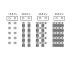
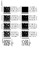
- the inkjet printing method shown in FIG. 1 is called a block method.
- printing is performed with the same nozzle, and the head is moved in the nozzle row direction by a distance (21.2 ⁇ m) of an output resolution of 1200 dpi.
- the printing of 1200 dpi is completed by the second scan.
- the landing of the droplet is continuously performed in “1 scan” and “2 scan” as shown in the figure, and streaks are likely to occur in the transport direction.
- the inkjet printing method shown in FIG. 2 is called an interleave method, in which the first scan in the transport direction prints by skipping one pixel with the same nozzle, and the second scan in the transport direction prints in the first scan.
- the pixels between the two parts are printed, then the head is moved in the direction of the nozzle row by the distance (21.2 ⁇ m) of the resolution of 1200 dpi, and the third and fourth prints are performed in the same manner to complete the printing of the output resolution of 1200 dpi. ..
- the landing order becomes periodic as in “1 scan” to “4 scans”, and streaks are likely to occur.
- the inkjet printing method shown in FIG. 3 is a so-called "random" landing random multipath method according to the present invention.
- Printing of 1200 dpi has been completed in a total of 8 passes so that the landing order is random.
- the number of passes may be further increased.
- the transport direction may be further thinned out to increase the number of passes.
- the droplets are landed randomly, so that the streaks are not noticeable.
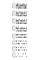
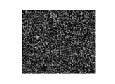
- random in the present invention is a method of forming a pattern under the premise that it is controlled within the condition range described later, and the whole is the liquid amount of dots or the mutual positional relationship of dots. Randomness or unpredictability without regularity such as identity or periodicity is recognized. Specifically, for example, it refers to the state shown in FIG.
- the reason for the manifestation of the effect of the present invention is that in the pattern forming method of the present invention, due to the landing location and the randomness of the order of the ink droplets, they are adjacent to each other in the printed image. It is considered that there is no periodicity between each pixel or dot, and streaks and unevenness are less likely to occur as a whole.
- Schematic diagram showing the pattern formation method by the block method Schematic diagram showing the pattern formation method by the interleave method
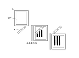
- Schematic diagram showing a pattern forming method by the random multipath method according to the present invention The figure which shows the image data which the gradation or density of each pixel is uniform
- the figure which shows the image data which the gradation or density of each pixel has a constant periodicity.
- Schematic diagram (front view) showing an inkjet printing device using a multipath method.
- Schematic diagram (top view) showing an inkjet printing device using a multipath method.
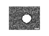
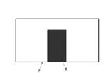
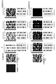
- Photograph of optical microscope at 100 times magnification of printed matter 3 The figure which shows the image data of the punched circle part of Example 3. Photograph of an optical microscope at 100 times the drawing circle of ⁇ 500 ⁇ m of printed matter 3 The figure which shows the image data of the punched circle part of Example 4. Photograph of an optical microscope at 100 times the drawing circle of ⁇ 500 ⁇ m of printed matter 4 Enlarged schematic diagram of a printed circuit board with a Cu wiring pattern The figure which shows the image data to be printed on the printed circuit board of Example 5. Explanatory drawing of wiring part image data of Example 6 Explanatory drawing of wiring part image data of Example 7. The figure which shows the image data of the solid part of Example 8.
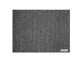
- Photograph of optical microscope at 100 times magnification of printed matter 8 Photograph of an optical microscope at 100 times the printed matter 9 (Comparative Example 1)
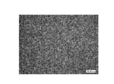
- FIG. 1 The figure which shows the case where the positions of the ejected dots which land a droplet are the same.
- Top view showing an inkjet printing apparatus 100 by a multipath method The figure which shows the method of printing with the inkjet printing apparatus 1 (the head moves in the X direction, and the substrate moves in the Y direction). The figure which shows the method of printing with the inkjet printing apparatus 100 (the head moves in the Y direction, and the substrate moves in the X direction). The figure which shows the method of printing with the inkjet printing apparatus which the substrate moves in both X direction and Y direction. The figure which shows the method of printing with the inkjet printing apparatus which the head moves in both X direction and Y direction.
- the pattern forming method of the present invention is a pattern forming method by an inkjet printing method based on image data of a pattern, and a plurality of ink ejection devices having a plurality of nozzle holes arranged in a row direction perpendicularly and parallel to the nozzle row direction of the ink ejection device.
- a method of forming a pattern by ejecting ink droplets from a nozzle onto a substrate as a print medium by rotating the ink the ratio ⁇ 2 of the viscosity ⁇ 1 at the temperature at the time of ejection and the viscosity ⁇ 2 at the temperature at the time of impact ⁇ 2 as the ink.
- ink having / ⁇ 1 of 100 or more and at least (1) the dots constituting the pattern formed on the substrate in correspondence with the gradation or density of each pixel constituting the image data of the pattern.
- the amount of the ink used to form the coating film is controlled so as not to have a constant periodicity with the adjacent dots and the entire coating film of the pattern is not uniform, or (2) on the substrate.
- the ink droplets used to form the coating film of the dots constituting the pattern are landed a plurality of times, and the positions of the dots on which the droplets are landed are each pixel constituting the image data. Is not in the order of the arranged rows and columns, and is characterized in that it is controlled so as not to have a certain periodicity. This feature is a technical feature common to or corresponding to the following embodiments.
- the pattern forming method of the present invention is (3) a pattern forming method by an inkjet printing method based on image data of a pattern, in which an ink ejection device having a plurality of nozzle holes or a substrate as a printing medium moves a plurality of times.
- the ink has a viscosity ⁇ 1 at the temperature at the time of ejection and a viscosity ⁇ 2 at the temperature at the time of impact.
- the ink having a ratio of ⁇ 2 / ⁇ 1 of 100 or more is used, and the droplets of the ink used for forming the coating film of the dots forming the pattern formed on the substrate are landed a plurality of times, and the above. It is characterized in that the positions of the dots on which the droplets are landed do not have a constant periodicity in the main scanning direction and the sub-scanning direction of the ink ejection device, and are controlled so as not to be continuous in the main scanning direction.
- the pixels do not overlap when the image data of the pattern is printed in an overlapping manner.
- the position of the dot on which the droplet is landed does not have a constant periodicity in the main scanning direction and the sub-scanning direction of the ink ejection device, and is divided into a plurality of parts so as not to be continuous in the main scanning direction. Then, it is preferable to sequentially print the divided image data in an overlapping manner.
- the ink ejection device relatively reciprocates in the main scanning direction from the viewpoint of preventing the occurrence of streaks and mottled unevenness, and the outbound route and the outbound route. It is preferable to eject ink droplets on both the return trips.
- the ink ejection device is relatively forward and reverse to the sub-scanning direction from the viewpoint of preventing the occurrence of streaks and mottled unevenness. It is preferable to move in a combination of directions.
- the pattern forming method of the above (3) is used for forming a coating film of dots constituting the pattern formed on the substrate from the viewpoint of preventing the occurrence of streaks and mottled unevenness.
- the amount of ink liquid corresponds to the gradation or density of each pixel constituting the image data of the pattern, does not have a constant periodicity with adjacent dots, and is not uniform as a whole coating film of the pattern. It is preferable to control such a method.
- one dot per dot forming the inner edge of the pattern portion at the boundary between the patterned portion and the non-patterned portion formed on the substrate is preferable to control so that the liquid amounts of the inks of the above inks are substantially the same.
- the amount of ink liquid per dot of the dots forming the edge of the convex portion with respect to the substrate having the convex portion is preferable to control so that they are substantially the same.
- the outer edge of the boundary between the inside and the outside of the bottom surface of the convex portion is formed on the substrate having the convex portion. It is preferable to control the dots to be formed so that the amount of ink liquid per dot is larger than that of the dots forming the edge of the convex portion.
- the outer edge surface of the boundary between the inside and the outside of the bottom surface of the convex portion with respect to the substrate having the convex portion is preferable to control the amount of liquid of the dots forming the above to continuously change from the surface in contact with the convex shape portion to the surface in the outer direction.
- the average thickness of the coating film of the dots constituting the pattern it is preferable to control the average thickness of the coating film of the dots constituting the pattern to be 15 ⁇ m or more from the viewpoint of preventing the occurrence of insulation and poor conductivity.
- the amount of the ink to be landed for forming the coating film of each dot constituting the pattern it is preferable to change the amount of the ink to be landed for forming the coating film of each dot constituting the pattern.
- any type of ink as the hot melt type, gelation type, or thixotropy type as the ink from the viewpoint of forming a high-definition pattern.
- the solder resist ink is used as the ink from the viewpoint of an application suitable for the object of the invention, for example, from the viewpoint that a problem in protecting a circuit pattern with an insulating film is a problem to be solved by the present invention. It is preferable to use.
- the pattern forming method of the present invention is preferably used in an inkjet printing apparatus.
- the pattern forming method of the present invention is a pattern forming method by an inkjet printing method based on image data of a pattern, and is a nozzle row of an ink ejection device in which a plurality of nozzle holes are arranged in a single row direction.
- the ink has a viscosity ⁇ 1 at the ejection temperature and an impact.
- the amount of the ink used to form the coating film of the dots forming the pattern formed on the substrate is adjacent to the gradation or density of each pixel constituting the image data of the pattern. It does not have a constant periodicity with the dots to be formed, and the entire coating film of the pattern is controlled so as not to be uniform, or (2) for forming a coating film of dots constituting the pattern formed on the substrate.
- the ink droplets used are landed a plurality of times, and the positions of the dots on which the droplets are landed are not in the order of the rows and columns in which the pixels constituting the image data are arranged. It is characterized in that it is controlled so as not to have a constant periodicity.
- (3) is a pattern forming method by an inkjet printing method based on image data of a pattern, in which an ink ejection device having a plurality of nozzle holes or a substrate as a printing medium moves a plurality of times from the nozzles of the ink ejection device.
- the ratio ⁇ 2 / ⁇ 1 of the viscosity ⁇ 1 at the temperature at the time of ejection and the viscosity ⁇ 2 at the temperature at the time of impact is 100 or more as the ink.
- the ink droplets used to form the coating film of the dots forming the pattern formed on the substrate are landed a plurality of times, and the dots are landed.
- the position is controlled so that the ink ejection device does not have a constant periodicity in the main scanning direction and the sub-scanning direction and is not continuous in the main scanning direction.
- the pattern forming method used in the present invention moves a plurality of nozzle holes vertically and parallel to the nozzle row direction of the ink ejection device in which a plurality of nozzle holes are arranged in a row direction, and moves from the nozzle to the print medium a plurality of times. It is characterized by using a so-called "multi-pass method" in which ink droplets are ejected and formed on the substrate. Details of the apparatus used in the present invention will be described later.
- the ink ejection device or the substrate as a printing medium having a plurality of nozzle holes moves a plurality of times, and the ink droplets are ejected from the nozzles of the ink ejection device to the substrate as the printing medium to form a pattern. It is characterized by using a method of forming.
- the ink used in the present invention is characterized in that the ratio ⁇ 2 / ⁇ 1 of the viscosity ⁇ 1 at the temperature at the time of ejection and the viscosity ⁇ 2 at the temperature at the time of landing is 100 or more. A detailed description of the ink will be described later. Hereinafter, embodiments and components of the present invention will be sequentially described.
- Pattern formation method by random drop multi-pass method dots forming a pattern formed on a substrate corresponding to the gradation or density of each pixel constituting the image data of the pattern. It is characterized in that the amount of the ink used to form the coating film is controlled so as not to have a constant periodicity with the adjacent dots and the entire coating film of the pattern is not uniform.
- non-uniform means that the difference in the amount of liquid between the dots is substantially the same within the range of ⁇ 5%, but the dots having the same amount of liquid do not line up periodically. say.
- the amount of ink used to form dots has a constant periodicity with adjacent dots
- random in the present specification, is a method of forming a pattern under the premise that it is controlled within the condition range described later, and the whole is the liquid amount of dots or the mutual positional relationship of dots. Randomness or unpredictability without regularity such as identity or periodicity is recognized. Specifically, for example, it refers to the state shown in FIG.
- the "dot” refers to the smallest unit pixel constituting the ink image formed on the print medium by the inkjet printing method, and refers to the coating film portion formed by one droplet of the ink liquid. Therefore, the pixel in the ink image corresponding to one pixel in the image data to be printed may be formed by a plurality of dots (droplets).
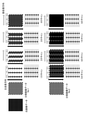
- the image data and the liquid amount distribution of the ink in this embodiment will be described. Since the random drop multipath method according to the present invention changes the liquid amount of dots according to the gradation or density of each pixel, the image data of the random drop multipass method is adjacent as shown in FIG. 6 as an example. It is preferable that the image is a gray image having 256 gradations that does not have a constant periodicity with the pixels.
- a gray image can be image-processed.
- a random multi-gradation gray image data as shown in FIG. 16 can be created by applying a noise filter to a 256-gradation 30% gray image using Adobe Photoshop.
- the black part of 0 to 86 gradation is 7pL
- the gray part of 87 to 172 gradation is 3.5pL
- the white part of 173 to 255 gradation is 0pL.
- the amount of liquid can be distributed.
- FIG. 7 is an image diagram of the liquid amount distribution of dots formed by printing based on the image data of FIG. By randomly arranging the amount of liquid, the occurrence of streaks and mottled unevenness can be suppressed.
- FIG. 8 is a schematic view showing the inkjet printing (printing) device 1 in the present embodiment.
- a carriage 2 having an inkjet head 3 having a resolution of 600 dpi for ejecting ink is mounted on a linear stage 4 in the X direction, and the head 3 is mounted in the X direction.
- a table 5 on which the substrate is placed is mounted on the linear stage 6 in the Y direction, and the table 5 moves in the Y direction (transport direction).
- the pattern formation by the random drop multipath method in the present embodiment can be performed by block printing, and FIG. 9 shows a method of printing 1200 dpi by block printing using one inkjet head having a resolution of 600 dpi.
- the inkjet head 3 shown in FIG. 8 moves in the Y direction (conveyance direction), and prints the first scan with the amount of liquid distributed according to the image data. After that, the head moves 21.2 ⁇ m (corresponding to one pixel of 1200 dpi) in the X direction, and the second scan is printed with the liquid amount distributed according to the image data, and the printing of 1200 dpi is completed.
- random multipath method A
- FIG. 10 is image data used in the random multipath method, and each dot is formed with a uniform amount of liquid. Further, each dot may be formed with different liquid volumes by using multi-gradation random image data as shown in FIG. 6 used in the random multi-pass method.
- the dots are landed at intervals, not continuous in the direction of the arranged rows and columns, and dots are formed so that the intervals are not constant.
- dots are formed in the same manner at positions where dots are not formed so that the dots do not overlap.
- the number of dots formed in each scan does not have to be constant. The number of scans may be further increased.
- FIG. 11 which describes the printing method in the present embodiment, shows a method of printing 1200 dpi by random impact using one inkjet head having a resolution of 600 dpi.
- the inkjet head prints by scanning four times in the Y direction (conveyance direction), it is 21.2 ⁇ m in the X direction.
- moving corresponding to one pixel of 1200 dpi
- printing is completed with a total of eight movements (passes) (see FIG. 8 for the apparatus).
- the embodiment of the present invention is a pattern forming method by an inkjet printing method based on image data of a pattern, which is an ink ejection device having a plurality of nozzle holes or printing.
- a substrate as a medium moves a plurality of times and droplets of ink are ejected from a nozzle of the ink ejection device onto the substrate as a printing medium to form a pattern
- the ink has a viscosity ⁇ 1 at the temperature at the time of ejection.
- ink having a ratio ⁇ 2 / ⁇ 1 to the viscosity ⁇ 2 at the time of impact is 100 or more, and the droplets of the ink used for forming the coating film of the dots forming the pattern formed on the substrate.
- the dots are landed a plurality of times, and the positions of the dots on which the droplets are landed do not have a constant periodicity in the main scanning direction and the sub-scanning direction of the ink ejection device, and are not continuous in the main scanning direction. It is characterized by controlling.
- random multipath method (B) the method satisfying the above control conditions is referred to as "random multipath method (B)".
- a plurality of nozzle holes move a plurality of times perpendicularly and parallel to the nozzle row direction of the ink ejection device in which a plurality of nozzle holes are arranged in a row direction.
- a method of ejecting ink droplets onto a substrate as a printing medium to form a pattern is used, in this embodiment, an ink ejection device having a plurality of nozzle holes or a substrate as a printing medium is used a plurality of times.
- a method of moving and ejecting ink droplets from the nozzle of the ink ejection device onto the substrate as the printing medium to form a pattern is used.
- the main scanning direction and the sub-scanning direction of the ink ejection device do not have to be perpendicular to or parallel to the nozzle row, and the ink ejection device and the printing medium may be used. It was found that even if only one of the substrates moves to form a pattern or both move to form a pattern, streaks and unevenness are unlikely to occur.
- the positions of the dots at which the droplets land are in the order of the rows and columns in which the pixels constituting the image data are arranged.
- the ink ejection device is controlled so as not to have a constant periodicity in the main scanning direction and the sub-scanning direction, and further controlled so as not to be continuous in the main scanning direction, the sub-scanning direction is partially continuous. However, it was found that streaks and unevenness are unlikely to occur.
- FIG. 29 shows a method of printing at a resolution of 2400 dpi by random landing and split printing using one inkjet head with a nozzle resolution of 600 dpi.
- the original image data in which each dot is formed with a uniform liquid amount is used, but each dot is formed with a different liquid amount by using the random original image data with multiple gradations as shown in FIG. You may.
- the original image data is divided into two, the divided image data is created, and then the divided image data is sequentially overlaid and printed. Therefore, the divided image data is created so that the pixels do not overlap when printed in layers. Further, the divided image data is created so that the positions of the dots on which the droplets land do not have a constant periodicity in the main scanning direction and the sub-scanning direction of the ink ejection device and are not continuous in the main scanning direction.
- the divided image data can be created by image processing software such as Adobe's image processing software Photoshop 2020. For example, a gray image is converted into monochrome two gradations by an error diffusion method using Photoshop, and a random image of black and white is produced. Next, the color tone of the image is inverted to create an inverted white and black image. The two obtained images are divided images of solid black data in which the landings are random and do not overlap.
- image processing software such as Adobe's image processing software Photoshop 2020. For example, a gray image is converted into monochrome two gradations by an error diffusion method using Photoshop, and a random image of black and white is produced. Next, the color tone of the image is inverted to create an inverted white and black image.
- the two obtained images are divided images of solid black data in which the landings are random and do not overlap.
- FIG. 31 shows a method of printing with a resolution of 2400 dpi by random landing using one inkjet head with a nozzle resolution of 600 dpi. In this method, printing is completed for each column in the main scanning direction.
- printing of columns in the main scanning direction is completed by, for example, one scan and two consecutive scans.
- the split printing as shown in FIG. 29, it is completed by two non-consecutive scans of one scan and five scans.
- the time required to complete the printing of the columns in the main scanning direction is relatively long, so that the ink can be easily fixed, the ink flow can be suppressed, and streaks and unevenness are less likely to occur.
- FIGS. 30A and 30B show a method of dividing the original image data into four and performing the same divided printing as in FIG. 29.
- the printing of the column in the main scanning direction is completed by four non-continuous scans of one scan, five scans, nine scans and thirteen scans.
- the ink having a relatively high viscosity at the time of impact or the ink having a relatively fast phase transition time is used.
- the ink is less likely to be fixed in a line in the main scanning direction, and streaks and unevenness are less likely to occur.
- by increasing the number of scans it is possible to reduce the occurrence of landing deviation due to the interaction with the ink degree (dot) landed earlier in the adjacent landing, and the pattern formation property is improved.
- random landing means that the positions of the dots at which the droplets land do not have a constant periodicity in the main scanning direction and the sub-scanning direction of the ink ejection device, and are not continuous in the main scanning direction. It means to control.
- FIG. 32 shows a method of performing split printing in the same manner as in FIG. 29, but in 1 scan and 5 scans, the positions of the dots ejected from the leftmost nozzle and the middle nozzle are the same. Is.
- Streaks and unevenness which are the problems to be solved in the present invention, are likely to occur when the positions of the dots on which the droplets land are periodic or regular in the direction of the column in the main scanning direction, but are periodic or in the direction of the row. It is hard to occur even if it is regular. Therefore, as shown in FIG. 32, even if the positions of the dots at which the droplets ejected from different nozzles are landed are the same in some scans, the occurrence of streaks and unevenness can be sufficiently suppressed.
- the ink ejection device relatively reciprocates in the main scanning direction and ejects ink droplets on both the outward and return paths.
- bidirectional printing a printing method satisfying the above control conditions is referred to as "bidirectional printing".
- FIG. 38 shows a method in which the ink ejection device reciprocates relatively in the main scanning direction and performs bidirectional printing in which ink droplets are ejected on both the outward path and the return path.
- the ink ejection device moves relatively in the direction of the arrow (moving on the outward path) while ejecting ink droplets.
- the ink ejection device moves relatively in the direction of the arrow so that a row of dots is formed on the adjacent right side of the row of dots formed in one scan, while ejecting ink droplets.
- Move relatively in the direction of the arrow (return movement). This is repeated, and printing is completed with a total of 8 scans.
- moving relatively means that only one of the ink ejection device and the substrate as the printing medium may move, or both of them may move, and the ink ejection device may move. It means that the ink ejection device moves relatively in the positional relationship between the ink and the substrate as a print medium.
- the substrate may be fixed and the ink ejection device may be moved in the direction of the arrow, or the ink ejection device may be fixed and the substrate may be moved in the direction opposite to the arrow. You may.
- the ink ejection device In one-way printing as shown in FIG. 29, the ink ejection device relatively reciprocates in the main scanning direction, but ejects ink droplets only on the outward path and only moves on the return path. Therefore, by performing bidirectional printing, the printing time can be shortened and the productivity is improved.
- the ink ejection device moves in a combination of forward and reverse directions with respect to the sub-scanning direction.
- FIG. 39 shows a method of performing forward / reverse mixed printing in which the ink ejection device moves in a combination of forward and reverse directions relative to the sub-scanning direction.
- the ink ejection device moves relatively in the main scanning direction and ejects ink droplets.
- the ink ejection device moves relatively in the direction of the arrow so that a row of dots is formed on the right side of the row of dots formed in one scan with an interval of one dot. It moves in the main scanning direction and ejects ink droplets.
- the ink ejection device moves relatively in the direction of the arrow so that a row of dots is formed between the row of dots formed in one scan and the row of dots formed in two scans, and further main. It moves in the scanning direction and ejects ink droplets. This is repeated, and printing is completed with a total of 8 scans.
- dots are formed so as to be adjacent to the formed dots. Adjacent dots are formed before the ink is fixed, which causes streaks and unevenness.
- dots are formed at intervals from the formed dots, so that adjacent dots are formed after the ink of the dots is fixed, and streaks and unevenness are less likely to occur.
- dots are formed at intervals from the formed dots, so that the occurrence of landing deviation can be reduced by the interaction with the ink (dots) that landed earlier in the adjacent landing. Pattern formation is improved.
- the amount of ink used to form a coating film of dots forming a pattern formed on a substrate further constitutes image data. It is also preferable to control so that the entire coating film of the pattern is not uniform, corresponding to the gradation or density of each pixel and does not have a constant periodicity with the adjacent dots.
- FIG. 43 shows a method of printing with a resolution of 2400 dpi by random landing using one inkjet head with a nozzle resolution of 600 dpi using multi-gradation image data.
- the image data used in the random multi-pass method may be used to form each dot with a uniform liquid volume, but the multi-gradation as shown in FIG. 43 may be formed.
- Random image data of the above may be used to form each dot with a different amount of liquid according to the gradation or density of each pixel. In this way, by combining the random drop multipath method and the random multipath method, the randomness of adjacent dots is further enhanced, and streaks and unevenness are less likely to occur.
- one dot forming the inner edge of the pattern portion at the boundary between the pattern portion and the non-pattern portion formed on the substrate (droplets). It is also preferable to control the amount of ink liquid per droplet) to be substantially the same.
- the liquid amount is substantially the same means that the difference in the liquid amount is within ⁇ 5%.
- the printed circuit board is a substrate having a convex shape portion such as a wiring board of an electronic device
- a dot (droplet) of dots (droplets) forming an edge of the convex shape portion with respect to the substrate having the convex shape portion. It is also preferable to control the amount of ink liquid per droplet) to be substantially the same.
- dots (droplets) forming the outer edge of the boundary between the inside and the outside of the bottom surface of the convex portion form dots (droplets) forming the edge of the convex portion. It is also preferable to control so that the amount of ink liquid per dot (droplet) is larger than that of).
- the amount of liquid of the dots (droplets) forming the outer edge surface of the boundary between the inside and the outside of the bottom surface of the convex shape portion is from the surface in contact with the convex shape portion. It is also a preferred embodiment to control the change continuously toward the surface in the outer direction.
- the average thickness of the coating film of dots (droplets) constituting the pattern is controlled to be 15 ⁇ m or more, although it depends on the performance of the ink used and the purpose of the pattern to be formed. However, it is preferable from the viewpoint of exhibiting the effect of the present invention.
- the ink used in the forming method of the present invention is characterized in that the ratio ⁇ 2 / ⁇ 1 of the viscosity ⁇ 1 at the temperature at which the ink is ejected and the viscosity ⁇ 2 at the temperature at the time of impact is 100 or more.
- the ratio ⁇ 2 / ⁇ 1 of the viscosity ⁇ 1 at the temperature at which the ink is ejected and the viscosity ⁇ 2 at the temperature at the time of impact is 100 or more.
- ⁇ 2 / ⁇ 1 100 or more, the generation of bulge can be suppressed and a high-definition pattern can be formed.
- the viscosity at the time of ink ejection and landing is not particularly limited as long as it is within the range satisfying the above ratio, but the viscosity ( ⁇ 1) when the temperature at the time of ejection is set to, for example, 75 ° C. is an inkjet. It is preferably in the range of 3 to 15 mPa ⁇ s from the viewpoint of the discharge property of the head.
- the viscosity ( ⁇ 2) when the temperature at the time of ink landing is room temperature (25 ° C.) is preferably 1 ⁇ 10 2 to 1 ⁇ 10 4 mPa ⁇ s.
- the viscosity ( ⁇ 2) is 1 ⁇ 10 2 to 1 ⁇ 10 4 mPa ⁇ s, the ink is fixed on the substrate at the time of landing, and the generation of bulge and the like can be suppressed.
- the pattern forming method according to the present invention it is possible to prevent the occurrence of insulation and poor conductivity, especially by using the ink. In particular, the effect is remarkable when a pattern is formed across different members or members having a convex shape.
- the "viscosity ⁇ 2 at the temperature at the time of impact” is the ink that arrives before the ink flow (not due to the impact of impact) due to the wet spread of the ink on the substrate is substantially generated. It can be said to be the viscosity, specifically, the viscosity reached within 1 second after the ink lands on the substrate, but in the present invention, it is the temperature of the substrate when the ink lands.
- the temperature of the head at the time when the ink is ejected from the head is used.
- the ink is set in a temperature-controllable stress-controlled rheometer (for example, Physica MCR300, manufactured by AntonioPaar), heated to 100 ° C., and cooled to 25 ° C. under the condition of a temperature lowering rate of 0.1 ° C./s. , Viscosity measurement.
- the measurement can be performed using a cone plate having a diameter of 75.033 mm and a cone angle of 1.017 ° (for example, CP75-1, manufactured by Antonio Par).
- the temperature control can be performed by using the temperature control device, for example, by the Pelche element type temperature control device (TEK150P / MC1) attached to the Physica MCR300.
- the condition of the viscosity ratio ⁇ 2 / ⁇ 1 of the ink according to the present invention can be appropriately satisfied by, for example, setting physical conditions such as the composition of the ink and the temperature and humidity at the time of landing of the ink.
- the ink preferably has the ability to change its viscosity by, for example, a phase change mechanism of any one of hot melt, thixotropy, and gelation.
- the condition of the viscosity ratio ⁇ 2 / ⁇ 1 according to the present invention can be satisfied.
- phase change mechanism by hot melt means viscosity by cooling from a state where it is heated (melted) and has a low viscosity (during discharge). A mechanism that shifts to a high state (at the time of landing). From the viewpoint of preferably expressing the phase change mechanism by hot melt, it is preferable to change the temperature of the ink between the time of ejection and the time of landing. For example, it is preferable to perform either or both of heating the ink at the time of ejection and cooling the ink at the time of landing.
- a heater for heating the ink filled in the inkjet head, a cooling means for cooling the substrate, and the like are used.
- the temperature adjusting means as described above can be appropriately used.
- Thixotropy is a property that exhibits intermediate properties between a plastic solid such as a gel and a non-Newtonian liquid such as a sol, and the viscosity changes with the passage of time.
- Phase change mechanism by thixotropy means that the viscosity is high because the action of shear stress is reduced or stopped from the state where the viscosity is low under the action of shear stress due to stirring or vibration (at the time of emission).
- a phase change mechanism that shifts to a state (after landing).
- a phase change mechanism by thixotropy can be developed by appropriately using a shear stress applying means for applying stirring or vibration (slight vibration) to the ink filled in the inkjet head.
- phase change mechanism due to gelation is the mutual relationship between the polymer network formed by chemical or physical aggregation, the aggregated structure of fine particles, etc., from the state where the viscosity is low (at the time of emission) due to the independent motility of the solute.
- the ink contains a gelling agent such as an oil gelling agent (details will be described later).
- the ink is heated to a sol-gel phase transition temperature (gelation temperature) or higher at the time of ejection to form a sol, and the ink is cooled to a sol-gel phase transition temperature (gelation temperature) or lower at the time of impact to gel.
- solification temperature sol-gel phase transition temperature
- the ink used in the present invention is preferably a thermosetting ink that contains a compound having a thermosetting functional group and a gelling agent and undergoes a sol-gel phase transition depending on the temperature. Further, it is more preferable that the thermosetting inkjet ink contains a compound having a photopolymerizable functional group and a photopolymerization initiator.
- thermosetting functional group is at least one selected from the group consisting of a hydroxy group, a carboxy group, an isocyanate group, an epoxy group, a (meth) acrylic group, a maleimide group, a mercapto group and an alkoxy group. It is preferable in that.
- the gelling agent is preferably held in a state of being uniformly dispersed in the cured film cured by light and heat, whereby it is possible to prevent the permeation of water into the cured film.
- Such a gelling agent is a compound of at least one of the compounds represented by the following general formula (G1) or (G2), and is dispersed in the cured film without impairing the curability of the ink. It is preferable in terms of points. Further, in inkjet printing, it is preferable in that the pinning property is good, the drawing can be performed with both the fine line and the film thickness, and the fine line reproducibility is excellent.
- General formula (G2): R 3 -COO-R 4 [In the formula, R 1 to R 4 each independently represent an alkyl chain having a linear moiety having 12 or more carbon atoms and may have a branch. ]
- the ketone wax represented by the general formula (G1) or the ester wax represented by the general formula (G2) has a linear or branched hydrocarbon group (alkyl chain) having 12 or more carbon atoms.
- the crystallinity of the gelling agent is further enhanced, the water resistance is improved, and more sufficient space is created in the following card house structure. Therefore, the ink medium such as the solvent and the photopolymerizable compound is easily encapsulated in the space, and the pinning property of the ink is further improved.
- the carbon number of the linear or branched hydrocarbon group (alkyl chain) is preferably 26 or less, and when it is 26 or less, the melting point of the gelling agent does not rise excessively, so that the ink is ejected. There is no need to overheat the ink when doing so.
- R 1 and R 2 , or R 3 and R 4 are linear hydrocarbon groups having 12 or more and 23 or less carbon atoms. Further, from the viewpoint of raising the gelation temperature of the ink and gelling the ink more rapidly after landing, carbon in which either R 1 or R 2 or R 3 or R 4 is saturated is saturated. It is preferably a hydrocarbon group having 12 or more and 23 or less atoms.
- both R 1 and R 2 or both R 3 and R 4 are saturated hydrocarbon groups having 11 or more and less than 23 carbon atoms.
- the content of the gelling agent is preferably in the range of 0.5 to 5.0% by mass with respect to the total mass of the ink.
- the content of the gelling agent in the inkjet ink is more preferably in the range of 0.5 to 2.5% by mass.
- the gelling agent crystallizes in the ink at a temperature equal to or lower than the gelation temperature of the ink.
- the gelling temperature is a temperature at which the gelling agent undergoes a phase transition from the sol to the gel when the solized or liquefied ink is cooled by heating, and the viscosity of the ink suddenly changes.
- the solified or liquefied ink is cooled while measuring the viscosity with a viscoelasticity measuring device (for example, MCR300, manufactured by Physica), and the temperature at which the viscosity rises sharply is set to the temperature of the ink. It can be a gelling temperature.
- the compound having a photopolymerizable functional group may be any compound having an action of polymerizing or cross-linking by causing a polymerization or cross-linking reaction by irradiation with active light to cure the ink.
- Examples of photopolymerizable compounds include radically polymerizable compounds and cationically polymerizable compounds.
- the photopolymerizable compound may be any of a monomer, a polymerizable oligomer, a prepolymer or a mixture thereof.
- the inkjet ink may contain only one type of the photopolymerizable compound, or may contain two or more types of the photopolymerizable compound.
- the radically polymerizable compound is preferably an unsaturated carboxylic acid ester compound, more preferably a (meth) acrylate.
- examples of such a compound include the above-mentioned compounds having a (meth) acrylic group.
- the cationically polymerizable compound may be an epoxy compound, a vinyl ether compound, an oxetane compound, or the like.
- the inkjet ink may contain only one type of the cationically polymerizable compound, or may contain two or more types of the cationically polymerizable compound.
- Photopolymerization initiator As the photopolymerization initiator, a photoradical initiator may be used when the photopolymerizable compound is a radically polymerizable compound, and a photoacid generator may be used when the photopolymerizable compound is a cationically polymerizable compound. preferable.
- photopolymerization initiator only one kind may be contained in the ink of the present invention, or two or more kinds may be contained.
- the photopolymerization initiator may be a combination of both a photoradical initiator and a photoacid generator.
- Photoradical initiators include cleaved radical initiators and hydrogen abstraction initiators.
- the ink used in the present invention may further contain a colorant, if necessary.
- the colorant may be a dye or a pigment, but a pigment is preferable because it has good dispersibility with respect to the constituents of the ink and is excellent in weather resistance.
- the dispersion of the pigment is such that the volume average particle size of the pigment particles is preferably in the range of 0.08 to 0.5 ⁇ m, the maximum particle size is preferably in the range of 0.3 to 10 ⁇ m, and more preferably 0.3 to 3 ⁇ m. It is preferable that the operation is performed so as to be within the range of.
- the dispersion of the pigment is adjusted by the selection of the pigment, the dispersant, and the dispersion medium, the dispersion conditions, the filtration conditions, and the like.
- a dispersant and a dispersion aid may be further contained.
- the total amount of the dispersant and the dispersion aid is preferably in the range of 1 to 50% by mass with respect to the pigment.
- the ink used in the present invention may further contain a dispersion medium for dispersing the pigment, if necessary.
- a solvent may be contained in the ink as a dispersion medium, but in order to suppress the residue of the solvent in the formed printed matter, the above-mentioned photopolymerizable compound (particularly a monomer having a low viscosity) is used as the dispersion medium. Is preferable.
- an oil-soluble dye or the like can be mentioned.
- the colorant may contain one or more types in the ink and may be toned to a desired color.
- the content of the colorant is preferably in the range of 0.1 to 20% by mass, and more preferably in the range of 0.4 to 10% by mass with respect to the total amount of the ink.
- the ink used in the present invention may further contain other components such as a polymerization inhibitor, a surfactant, a curing accelerator, a coupling agent, and an ion scavenger as long as the effects of the present invention can be obtained. Only one kind of these components may be contained in the ink, or two or more kinds thereof may be contained in the ink. Further, from the viewpoint of curability, solvent-free is originally preferable, but a solvent can be added to adjust the ink viscosity.
- the viscosity of the ink used in the present invention at 25 ° C. is in the range of 1 to 1 ⁇ 10 4 Pa ⁇ s, so that the ink is sufficiently gelled when it lands and the temperature drops to room temperature, and the pinning property is improved. It is preferable in that it becomes good.
- the viscosity of the ink of the present invention at 80 ° C. is preferably in the range of 3 to 20 mPa ⁇ s, and is in the range of 7 to 9 mPa ⁇ s. Is more preferable.
- the ink used in the present invention preferably has a phase transition point in the range of 40 ° C. or higher and lower than 100 ° C.
- the phase transition point is 40 ° C. or higher, the ink rapidly gels after landing on the print medium, so that the pinning property becomes higher. Further, when the phase transition point is less than 100 ° C., the ink handling property becomes good and the ejection stability becomes high.
- the phase transition point of the ink is more preferably in the range of 40 to 60 ° C.
- the average dispersed particle size of the pigment particles according to the present invention is preferably in the range of 50 to 150 nm, and the maximum particle size is preferably in the range of 300 to 1000 nm. .. A more preferable average dispersed particle size is in the range of 80 to 130 nm.
- the average dispersed particle size of the pigment particles in the present invention means a value obtained by a dynamic light scattering method using a data sizer nano ZSP manufactured by Malvern. Since the ink containing the colorant has a high concentration and does not transmit light with this measuring device, the ink is diluted 200 times before measurement. The measurement temperature is normal temperature (25 ° C).
- the ink used in the present invention is preferably a solder resist ink for forming a solder resist pattern used for a printed circuit board.
- the solder resist pattern is formed by using the ink, it is possible to prevent the permeation of water into the solder resist pattern, and as a result, the adhesion between the copper foil and the solder resist pattern interface on the printed circuit board is improved. In addition, migration of copper can be prevented and deterioration of insulating property can be suppressed.
- the method for forming a solder resist pattern using the ink used in the present invention includes the following (1) a step of ejecting ink from a nozzle of an inkjet head and landing it on a circuit-formed printed circuit board, and the following (3). It is preferable to include a step of heating the ink to perform main curing.
- the ink used in the present invention contains a compound having a photopolymerizable functional group and a photopolymerization initiator, the landed ink is irradiated with active light during the steps (1) and (3) above. It is preferable to include a step of temporarily curing the ink (step (2)).
- Step (1) droplets of the ink of the present invention are ejected from an inkjet head and landed on a printed circuit board, which is a printing medium, at a position corresponding to a solder resist pattern to be formed, and patterned.
- the ejection method from the inkjet head may be either an on-demand method or a continuous method.
- the ejection stability can be improved by ejecting ink droplets from the inkjet head in a heated state.
- the temperature of the ink at the time of ejection is preferably in the range of 40 to 100 ° C., and more preferably in the range of 40 to 90 ° C. in order to further improve the ejection stability.
- the temperature of the ink when filled in the inkjet head is from (gelling temperature +10) ° C. to (gelling).
- the temperature is preferably set to +30) ° C.
- the temperature of the ink in the inkjet head is less than (gelling temperature +10) ° C., the ink gels in the inkjet head or on the nozzle surface, and the ink ejection property tends to deteriorate.
- the temperature of the ink in the inkjet head exceeds (gelation temperature +30) ° C., the ink becomes too high, and the ink components may deteriorate.
- the method of heating the ink is not particularly limited.
- at least one of the ink tank, the supply pipe, the ink supply system such as the front chamber ink tank immediately before the head, the pipe with a filter, the piezo head, etc. constituting the head carriage is heated by a panel heater, a ribbon heater, heat insulating water, or the like.
- the amount of ink droplets to be ejected is preferably in the range of 2 to 20 pL in terms of printing speed and image quality.
- the printed circuit board is not particularly limited, and is, for example, paper phenol, paper epoxy, glass cloth epoxy, glass polyimide, glass cloth / non-woven cloth epoxy, glass cloth / paper epoxy, synthetic fiber epoxy, fluorine / polyethylene / PPO / cyanate ester.
- Step (2) In the step (2), the ink landed in the step (1) is irradiated with an active light beam to temporarily cure the ink.
- the active ray can be selected from, for example, electron beam, ultraviolet ray, ⁇ ray, ⁇ ray, X-ray and the like, but ultraviolet ray is preferable. Irradiation of ultraviolet rays can be carried out under the condition of a wavelength of 395 nm by using, for example, a water-cooled LED manufactured by Phoseon Technology. By using the LED as a light source, it is possible to suppress poor curing of the ink due to melting of the ink by the radiant heat of the light source.
- the peak illuminance on the surface of the solder resist pattern of ultraviolet rays having a wavelength in the range of 370 to 410 nm is preferably in the range of 0.5 to 10 W / cm 2 , more preferably 1 to 5 W / cm 2 . Do so so that it is within the range.
- the amount of light applied to the solder resist pattern is preferably less than 500 mJ / cm 2 . Irradiation with active light is preferably performed within 0.001 to 300 seconds after the ink lands, and more preferably within 0.001 to 60 seconds in order to form a high-definition solder resist pattern. ..
- Step (3) In the step (3), after the temporary curing of (2), the ink is further heated to be fully cured.
- a heating method for example, it is preferable to put the oven in an oven set in the range of 110 to 180 ° C. for 10 to 60 minutes.
- the ink used in the present invention can be used not only as the ink for forming the solder resist pattern described above, but also as an adhesive for electronic parts, a sealing agent, a circuit protective agent, and the like.
- the portion where the solder resist pattern is provided is not particularly limited, but as described above, when it is formed across different members or when it is formed over uneven members. , The effect of the present invention is particularly significant.
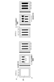
- the figure shown in FIG. 8 is a schematic view showing an inkjet printing apparatus 1 by a multipath method; a front view of A and a top view of B.
- the inkjet printing device 1 is basically a printing device that ejects ink by a multipath method in which the head 3 reciprocates to perform overlay printing, and moves the carriage 2 to which the head is attached and the carriage 2 X. It includes a directional linear stage 4, a table 5 on which a substrate is installed, a Y-direction linear stage 6 for moving the table 5, and the like.
- the inkjet printing apparatus 1 prints by moving the head 3 in the X direction and moving the table 5 on which the substrate is placed in the Y direction.
- the inkjet printing device 1 includes a device for controlling ink ejection from the head 3 and a computer for controlling the XY stage.
- the computer that controls the XY stage controls the operation of the XY stage based on the image data.
- the computer is equipped with a CPU (Central Processing Unit), a ROM (Read Only Memory), a RAM (Random Access Memory), and the like.
- the printing method in the X direction is performed by mounting the carriage 2 to which the head 3 is attached on the linear stage 4 in the X direction and moving the carriage 2 to a desired position by a computer that controls the XY stage. Further, the printing method in the Y direction is performed by moving the table 5 on which the substrate is installed in the Y direction and ejecting ink from the head when the substrate passes under the head.
- the encoder installed on the linear stage 6 in the Y direction and the device for controlling the ejection of ink from the head 3 are interlocked with each other, and the ink is ejected at the resolution of the image data according to the encoder signal.
- the head When printing at a resolution higher than the resolution of the head in the X direction, the head is moved a plurality of times in the X direction to print. For example, when printing 2400 dpi with one inkjet head with a resolution of 600 dpi, the head prints the first scan in the Y direction, then moves 10.6 ⁇ m in the X direction (equivalent to one pixel of 2400 dpi) and moves in the Y direction. Print the second scan. Further, the head moves 10.6 ⁇ m in the X direction to print the third scan in the Y direction, then moves 10.6 ⁇ m in the X direction to print the fourth scan in the Y direction, and the process is completed.
- bidirectional printing there is a case where printing is performed in only one direction, but there is also a case where printing is performed in a reciprocating manner (referred to as bidirectional printing). If the print area is larger than the head width, the print area is moved in the X direction by the head width to perform printing.
- the inventor does not have to make the main scanning direction and the sub-scanning direction of the ink ejection device perpendicular to or parallel to the nozzle row, and the ink ejection device and the substrate as a printing medium have a substrate. It was found that streaks and unevenness are unlikely to occur even if only one of them moves to form a pattern or both move to form a pattern.
- the ink ejection device (synonymous with the above-mentioned "head") has a plurality of nozzle holes for ejecting ink.
- the nozzle holes are preferably arranged in a row, but are synonymous with the nozzle row, the main scanning direction of the head (synonymous with the "Y direction”), and the sub-scanning direction (synonymous with the "X direction”).
- FIG. 41 shows a printing method when the direction of the nozzle row is not vertical or parallel in both the X direction and the Y direction, but is oblique.
- An inkjet printing device having an oblique nozzle row can also be used in the pattern forming method of the present invention.
- FIG. 42 shows a printing method when the direction of the ink ejection device itself is not vertical or parallel in both the X direction and the Y direction, but is oblique.
- the angle between the ink ejection device and the main scanning direction By appropriately changing the angle between the ink ejection device and the main scanning direction, the spacing between the formed dots can be changed, so that the nozzle resolution can be increased without adding an ink ejection device.
- Such an inkjet printing device can also be used in the pattern forming method of the present invention.
- printing is performed by moving the head in the X direction and moving the substrate in the Y direction, but inkjet printing in which the head moves in the Y direction and the substrate moves in the X direction.
- the device, the inkjet printing device in which the substrate moves in the X direction and the Y direction, and the inkjet printing device in which the head moves in the X direction and the Y direction can also be used in the pattern forming method of the present invention.
- FIG. 34 shows a method of printing with the inkjet printing apparatus 1.
- the head In one scan, the head is fixed, and when the substrate moves in the direction of the arrow and passes under the head, ink droplets are ejected from the head, so that the positional relationship between the substrate and the head is relative.
- the head moves in the main scanning direction.
- the head moves in the direction of the arrow, and the substrate moves again in the direction of the arrow to eject ink droplets. This is repeated to complete printing.
- the carriage 2 to which the head 3 is attached is mounted on the linear stage 6 in the Y direction, and is moved to a desired position by a computer that controls the XY stage.
- the table 5 on which the substrate is installed moves in the X direction and prints in the next main scanning direction in the Y direction.
- the encoder installed on the linear stage 4 in the X direction and the device that controls the ejection of ink from the head 3 work together to print ink at the resolution of the image data according to the encoder signal. Discharge.
- FIG. 35 shows a method of printing with the inkjet printing apparatus 100.
- the head moves on the fixed substrate in the main scanning direction to eject ink droplets.
- the substrate moves in the arrow direction, so that the head moves relatively in the sub-scan direction in the positional relationship between the substrate and the head.
- the ink ejection device moves on the fixed substrate in the main scanning direction to eject ink droplets. This is repeated to complete printing.
- FIG. 36 shows a method of printing with an inkjet printing device in which the substrate moves in both the X direction and the Y direction.
- the head In one scan, the head is fixed, and when the substrate moves in the direction of the arrow and passes under the head, ink droplets are ejected from the head, so that the positional relationship between the substrate and the head is relative.
- the head moves in the main scanning direction.
- the substrate moves in the arrow direction, so that the head moves relatively in the sub-scan direction in the positional relationship between the substrate and the head.
- the ink ejection device moves on the fixed substrate in the main scanning direction to eject ink droplets. This is repeated to complete printing.
- FIG. 37 shows a method of printing with an inkjet printing device in which the head moves in both the X direction and the Y direction.
- the head moves on the fixed substrate in the main scanning direction to eject ink droplets.
- the head moves in the direction of the arrow, and the substrate is moved again in the direction of the arrow to eject ink droplets. This is repeated to complete printing.
- the number of scans can be reduced and the printing time can be shortened.
- FIG. 40 shows a method of performing printing with a resolution of 2400 dpi by split printing using four inkjet heads with a nozzle resolution of 600 dpi.
- the four inkjet heads are staggered and attached to the carriage so that the pitch has a resolution of 2400 dpi.
- FIGS. 30A and 30B when printing with a resolution of 2400 dpi using one inkjet head with a nozzle resolution of 600 dpi, it is necessary to perform 16 scans using four divided image data. However, as shown in FIG. 40, when four inkjet heads are attached by shifting them, the steps of 1 scan to 4 scans in FIG. 30A can be performed in one scan, so that a total of four scans can be performed. Printing can be completed with, and printing time can be shortened.
- a random multi-gradation gray image data as shown in FIG. 16 can be created by applying a noise filter to a 30% gray image of 256 gradations using Adobe Photoshop. Based on this image data, for example, the black part of 0 to 86 gradation is 7pL, the gray part of 87 to 172 gradation is 3.5pL, and the white part of 173 to 255 gradation is 0pL. Allocate the amount.
- a method of printing by the random multi-pass method in the present invention a method of dividing the original image into a plurality of random non-overlapping images and printing, or a method of landing at random by an inkjet ejection control system using a function such as a random number. There is a way to do it.
- the divided image data can be created by the following method. It can be created with image processing software such as Adobe's image processing software Photoshop 2020. For example, a gray image is converted into monochrome and two gradations by an error diffusion method using Photoshop, and a random image of black and white is created. do. Next, the color tone of the image is inverted to create an inverted white and black image.
- image processing software such as Adobe's image processing software Photoshop 2020.
- a gray image is converted into monochrome and two gradations by an error diffusion method using Photoshop, and a random image of black and white is created. do.
- the color tone of the image is inverted to create an inverted white and black image.
- Example 1 [Ink preparation] ⁇ Preparation of pigment dispersion> The dispersant and dispersion medium shown below are placed in a stainless beaker, heated and dissolved on a hot plate at 65 ° C. for 1 hour, cooled to room temperature, and then a pigment is added to the zirconia having a diameter of 0.5 mm. It was placed in a glass bottle together with 200 g of beads and sealed. This was dispersed in a paint shaker until the particle size was desired, and then the zirconia beads were removed.
- the prepared dispersion was mixed with the following formulation, and then filtered through a Teflon (registered trademark) 3 ⁇ m membrane filter manufactured by ADVATEC to prepare an ink.
- the viscosity ( ⁇ 1) at an ink ejection temperature of 75 ° C. was 10 mPa ⁇ s
- the viscosity ( ⁇ 2) at room temperature (25 ° C.), which was the landing temperature was 1 ⁇ 10 4 mPa ⁇ s. .. That is, the viscosity ratio ⁇ 2 / ⁇ 1 was 1000.
- the same ink was used in the examples and comparative examples described below.
- Print pattern Using a linear XY stage with one inkjet head (KM1800iSHC-C: manufactured by Konica Minolta: resolution 600 dpi) and a control system (IJCS-1: manufactured by Konica Minolta), the following conditions are applied to the optical PET film that is the substrate.
- the print pattern was printed in 1 and exposed and cured with an irradiation energy of 500 mJ / cm 2 with a UV-LED light source having a wavelength of 395 nm to prepare a printed matter 1.
- a photograph of an optical microscope at 100 times magnification of printed matter 1 is shown in FIG.
- Printing pattern A blank circle with a ⁇ of 100 to 1000 ⁇ m is placed in a solid 70 mm ⁇ 70 mm square.
- Image data of the solid See Fig. 12 (256 gradations 50% gray is used for the noise filter of Adobe's image processing software Photoshop 2020.
- Example 2 Using a linear XY stage with one inkjet head (KM1800iSHC-C: manufactured by Konica Minolta: resolution 600 dpi) and a control system (IJCS-1: manufactured by Konica Minolta), the following conditions are applied to the optical PET film that is the substrate.
- the print pattern is printed by the random multi-pass method shown in the example of the present embodiment in the order of numbers by moving the head of 600 dpi 8 times in the transport direction ⁇ 1 movement in the head nozzle row direction, and the wavelength is 395 nm.
- a printed matter 2 was produced by exposure and curing with an irradiation energy of 500 mJ / cm 2 with a UV-LED light source.
- Printing pattern A blank circle with ⁇ of 100 to 1000 ⁇ m is placed in a square of 70 mm ⁇ 70 mm.
- Image data of solid part See Fig. 15. Resolution: 1200 dpi ⁇ 1200 dpi (conveyance direction) Number of passes: 8 times (600 dpi x 4 x 2) Distance traveled in the direction of the head nozzle row between passes: 21.2 ⁇ m
- Printing method Random pass Liquid volume distribution: 10.5pL on the entire surface Head temperature (ink ejection temperature): 75 ° C
- Substrate temperature temperature at the time of ink landing): Room temperature (25 ° C)
- Example 3 The printed matter 3 was produced in the same manner as in Example 1 except that the printing conditions were changed to the following conditions.
- FIG. 17 is a photograph of an optical microscope at 100 times magnification of printed matter 3.
- FIG. 19 is a photograph of an optical microscope at 100 times a drawing circle having a diameter of 500 ⁇ m.
- Print pattern Place a punched circle with ⁇ of 100 to 1000 ⁇ m in a square of 70 mm x 70 mm
- Image data of the punched circle See Fig. 18 (without bordering the punched circle)
- Image data of solid part See Fig.
- FIG. 21 is a photograph of an optical microscope at 100 times the drawing circle of ⁇ 500 ⁇ m of the printed matter 4.
- Image data of the punched circle part Fig. 20 (Unified with gray of gradation 155 so that the edge of the punched circle and one pixel have the same liquid volume)
- FIG. 22 is an enlarged schematic view of a printed circuit board having a Cu wiring pattern
- FIG. 23 is an image data to be printed on the printed circuit board.
- Example 6 As shown in FIG. 24, the printed matter 6 was produced in the same manner as in Example 5 except that the image data was changed to a liquid amount of 10.5 pL for one pixel in the portion in contact with the Cu wiring pattern.
- Example 7 As shown in FIG. 25, the image data is changed to a continuous thickness such that one pixel in contact with the Cu wiring pattern has a liquid volume of 10.5 pL and one pixel around it has a continuous thickness of 7 pL.
- the printed matter 7 was produced in the same manner as in Example 5.
- Example 8 >> The printed matter 8 was produced in the same manner as in Example 5 except that the printing conditions were changed to the following conditions.
- FIG. 27 is a photograph of an optical microscope at 100 times magnification of printed matter 8.
- Solid image data See Fig. 26 (256 gradation gray is converted to random multi-gradation by the same filter processing as above).
- Resolution 1200 dpi x 1200 dpi (transport direction)
- Number of passes 2 times (600 dpi x 2)
- Distance traveled in the direction of the head nozzle row between passes 21.2 ⁇ m
- Printing method Block liquid volume distribution: 0 to 86 gradation 14pL 87-172 gradation 7pL 173 to 255 gradation 0pL (no droplets added)
- Example 9 Using a linear XY stage with one inkjet head (KM1800iSHC-C: manufactured by Konica Minolta: nozzle resolution 600 dpi) and a control system (IJCS-1: manufactured by Konica Minolta), the following is applied to the optical PET film that is the substrate.
- a print pattern was printed under the conditions, and exposed and cured with an irradiation energy of 500 mJ / cm 2 with a UV-LED light source having a wavelength of 395 nm to prepare a printed matter 11.
- Print pattern A blank circle with ⁇ of 100 to 1000 ⁇ m is placed in a square of 70 mm ⁇ 70 mm.
- Image data of solid part Refer to Fig. 31, original image data Resolution: 2400 dpi ⁇ 2400 dpi (conveyance direction)
- Printing method Random multipath, see Fig. 31
- Liquid volume distribution 3.5 pL over the entire surface Head temperature (ink ejection temperature): 75 ° C
- Substrate temperature (temperature at the time of ink landing): Room temperature (25 ° C)
- Example 10 [Divided printing (number of image segmented 2)] Regarding the image data, as shown in FIG. 29, when the solid image data is printed in layers, the pixels do not overlap, and the order of the rows and columns in which the pixels are arranged is not constant.
- the divided image data No. is divided by image processing software so as not to have periodicity. 1 and No. 2 was produced. Then, under the following conditions, the divided image data were sequentially overlaid and printed.
- the printed matter 12 was produced in the same manner as in Example 9 except that the image data and the printing conditions were changed to the following conditions.
- Print pattern A blank circle with ⁇ of 100 to 1000 ⁇ m is placed in a square of 70 mm ⁇ 70 mm.
- Image data of solid part: Fig. 29, refer to original image data
- Printing method Random multipath, see Fig. 29
- Example 11 [Divided printing (number of image segmented 4)]
- the printed matter 13 was produced in the same manner as in Example 10 except that the number of divisions of the image data and the printing conditions were changed to the following conditions.
- Print pattern A blank circle with ⁇ of 100 to 1000 ⁇ m is placed in a square of 70 mm ⁇ 70 mm.
- Image data of solid part Refer to FIGS. 30A and B, original image data Number of image divisions: 4 Divided image data: Refer to FIGS. 30A and B, Divided image data Resolution: 2400 dpi x 2400 dpi (transport direction) Number of passes: 16 times (600 dpi x 16)
- Printing direction main scanning direction
- One-way printing Printing direction (secondary scanning direction): Positive direction printing Head nozzle row direction movement distance between passes: 10.6 ⁇ m
- Printing method Random multipath, see FIGS. 30A and B
- Liquid volume distribution 3.5 pL over the entire surface Head temperature (ink ejection temperature): 75 ° C
- Substrate temperature temperature at the time of ink landing): Room temperature (25 ° C)
- Example 12 [Bidirectional printing] A printed matter 14 was produced in the same manner as in Example 10 except that the printing conditions were changed to the following conditions.
- Print pattern A blank circle with ⁇ of 100 to 1000 ⁇ m is placed in a square of 70 mm ⁇ 70 mm.
- Image data of solid part: Fig. 38 refer to original image data Number of image divisions: 2 Divided image data: Refer to FIG. 38, divided image data Resolution: 2400 dpi x 2400 dpi (transport direction) Number of passes: 8 times (600 dpi x 8)
- Printing method Random multipath, see Fig. 38 Liquid volume distribution: 3.5 pL on the entire surface Head temperature (ink ejection temperature): 75 ° C
- Substrate temperature temperature at the time of ink landing): Room temperature (25 ° C)
- Example 13 [Forward / reverse mixed printing] A printed matter 15 was produced in the same manner as in Example 10 except that the printing conditions were changed to the following conditions.
- Print pattern A blank circle with ⁇ of 100 to 1000 ⁇ m is placed in a square of 70 mm ⁇ 70 mm.
- Image data of solid part Fig. 39, refer to original image data
- Printing method Random multipath, see Fig. 39
- Substrate temperature (temperature at the time of ink landing): Room temperature (25 ° C)
- Example 14 [Random drop multipath method and random multipath method] Using a linear XY stage with one inkjet head (KM1800iSHC-C: manufactured by Konica Minolta: nozzle resolution 600 dpi) and a control system (IJCS-1: manufactured by Konica Minolta), the following is applied to the optical PET film that is the substrate. A print pattern was printed under the conditions, and exposed and cured with an irradiation energy of 500 mJ / cm 2 with a UV-LED light source having a wavelength of 395 nm to prepare a printed matter 16.
- KM1800iSHC-C manufactured by Konica Minolta: nozzle resolution 600 dpi
- IJCS-1 manufactured by Konica Minolta
- the printed matter 16 was produced by distributing the liquid amount corresponding to the gradation of each pixel of the image data.
- Print pattern A blank circle with a ⁇ of 100 to 1000 ⁇ m is placed in a square of 70 mm ⁇ 70 mm.
- Image data of solid part Refer to Fig. 43 and image data (256 gradations 30% gray is used in Adobe's image processing software Photoshop 2020). Converted to random multi-tone gray using noise filtering) Resolution: 2400 dpi x 2400 dpi (transport direction) Number of passes: 8 times (600 dpi x 8)
- Printing method Random multipath, see Fig.
- Example 15 [Divided printing on printed circuit board (number of image segmentation 2)]
- FIG. 28 is a photograph of an optical microscope at 100 times magnification of printed matter 9.
- Printing pattern A blank circle with ⁇ of 100 to 1000 ⁇ m is placed in a square of 70 mm ⁇ 70 mm.
- Image data of solid part See Fig. 15 Resolution: 2400 dpi ⁇ 2400 dpi (conveyance direction) Number of passes: 4 times (600 dpi x 4) Distance traveled in the direction of the head nozzle row between passes: 10.6 ⁇ m
- Printing method Block liquid volume distribution: 3.5 pL on the entire surface
- FIG. 22 is an enlarged schematic view of a printed circuit board having a Cu wiring pattern
- FIG. 23 is an image data to be printed on the printed circuit board.
- Print pattern A blank circle with ⁇ of 100 to 1000 ⁇ m is placed in a square of 70 mm ⁇ 70 mm.
- Image data of solid part Fig. 44, refer to original image data
- Printing method Interleave, see Fig. 44
- Substrate temperature temperature at the time of ink landing): Room temperature (25 ° C)
- ⁇ Average film thickness> Using a film thickness meter (Digimicro MH-15M + TC-101A: manufactured by Nikon Corporation), the average film thickness was calculated by measuring four corners of a square of 70 mm ⁇ 70 mm in the print pattern and five points in the center.
- ⁇ Pattern formation> A drawing circle having a diameter of 500 ⁇ m was observed with an optical microscope to evaluate the pattern forming property.
- ⁇ The outline of the punched circle almost reproduces the printed image
- ⁇ The contour of the punched circle is slightly uneven, but there is no problem in pattern formation. Is deteriorated
- ⁇ The outline of the drawn circle is crushed and the pattern is not formed.
- Adhesion residual rate 100% Adhesive residual rate 80% or more and less than 100%
- Inkjet printing device 2 Carriage 3 Head 4 X-direction linear stage 5 Table 6 Y-direction linear stage 7 Printed circuit board 8 Copper wiring (height 15 ⁇ m, width 100 ⁇ m) 9 Ink ejection device 10 Substrate (printing medium) 100 Inkjet printing equipment
Landscapes
- Engineering & Computer Science (AREA)
- Physics & Mathematics (AREA)
- Quality & Reliability (AREA)
- Mathematical Physics (AREA)
- General Engineering & Computer Science (AREA)
- General Physics & Mathematics (AREA)
- Theoretical Computer Science (AREA)
- Ink Jet (AREA)
- Application Of Or Painting With Fluid Materials (AREA)
- Manufacturing Of Printed Wiring (AREA)
- Particle Formation And Scattering Control In Inkjet Printers (AREA)
Priority Applications (7)
| Application Number | Priority Date | Filing Date | Title |
|---|---|---|---|
| CN202180053394.5A CN115989090B (zh) | 2020-09-03 | 2021-08-05 | 图案形成方法以及喷墨印刷装置 |
| JP2022504059A JP7078196B1 (ja) | 2020-09-03 | 2021-08-05 | パターン形成方法 |
| EP21864052.2A EP4209280B1 (en) | 2020-09-03 | 2021-08-05 | Method of pattern formation |
| CN202311653251.5A CN117644735B (zh) | 2020-09-03 | 2021-08-05 | 图案形成方法以及喷墨印刷装置 |
| TW110130448A TWI792501B (zh) | 2020-09-03 | 2021-08-18 | 圖型形成方法及噴墨印刷裝置 |
| TW112100196A TWI819944B (zh) | 2020-09-03 | 2021-08-18 | 圖型形成方法及噴墨印刷裝置 |
| JP2022081956A JP7810059B2 (ja) | 2020-09-03 | 2022-05-19 | パターン形成方法及びインクジェット印刷装置 |
Applications Claiming Priority (2)
| Application Number | Priority Date | Filing Date | Title |
|---|---|---|---|
| JP2020147933 | 2020-09-03 | ||
| JP2020-147933 | 2020-09-03 |
Publications (1)
| Publication Number | Publication Date |
|---|---|
| WO2022049994A1 true WO2022049994A1 (ja) | 2022-03-10 |
Family
ID=80491700
Family Applications (1)
| Application Number | Title | Priority Date | Filing Date |
|---|---|---|---|
| PCT/JP2021/029174 Ceased WO2022049994A1 (ja) | 2020-09-03 | 2021-08-05 | パターン形成方法 |
Country Status (5)
| Country | Link |
|---|---|
| EP (1) | EP4209280B1 (https=) |
| JP (2) | JP7078196B1 (https=) |
| CN (2) | CN115989090B (https=) |
| TW (2) | TWI792501B (https=) |
| WO (1) | WO2022049994A1 (https=) |
Cited By (1)
| Publication number | Priority date | Publication date | Assignee | Title |
|---|---|---|---|---|
| WO2023166577A1 (ja) * | 2022-03-02 | 2023-09-07 | コニカミノルタ株式会社 | パターン形成方法及びインクジェット印刷装置 |
Families Citing this family (1)
| Publication number | Priority date | Publication date | Assignee | Title |
|---|---|---|---|---|
| WO2025210995A1 (ja) * | 2024-04-02 | 2025-10-09 | コニカミノルタ株式会社 | インクジェット式画像形成装置及びその制御方法、並びに、回路基板の製造方法及び回路基板 |
Citations (10)
| Publication number | Priority date | Publication date | Assignee | Title |
|---|---|---|---|---|
| JP2003309369A (ja) | 2002-04-16 | 2003-10-31 | Seiko Epson Corp | 多層配線基板、多層配線基板の製造方法、電子デバイス及び電子機器 |
| JP2006150788A (ja) * | 2004-11-30 | 2006-06-15 | Konica Minolta Medical & Graphic Inc | 画像記録方法及びインクジェット記録装置 |
| JP2006289722A (ja) * | 2005-04-08 | 2006-10-26 | Konica Minolta Medical & Graphic Inc | インクジェット記録装置及びインクジェット記録方法 |
| JP2009230018A (ja) * | 2008-03-25 | 2009-10-08 | Toppan Printing Co Ltd | インクジェット塗布装置および画素形成基板の製造方法およびカラーフィルタの製造方法および有機機能性素子の製造方法 |
| JP2010231287A (ja) | 2009-03-26 | 2010-10-14 | Seiko Epson Corp | タッチパネルとその製造方法及び表示装置製造方法並びに電子機器製造方法 |
| JP2012162057A (ja) | 2011-02-09 | 2012-08-30 | Konica Minolta Holdings Inc | 量子化装置、量子化方法及び画像形成装置 |
| WO2015002316A1 (ja) | 2013-07-05 | 2015-01-08 | コニカミノルタ株式会社 | 絶縁パターンの形成方法 |
| JP2015033657A (ja) * | 2013-08-07 | 2015-02-19 | パナソニック株式会社 | インクジェット印刷方法 |
| JP2019005946A (ja) * | 2017-06-22 | 2019-01-17 | コニカミノルタ株式会社 | インクジェット記録装置及び画像記録方法 |
| JP2019217669A (ja) * | 2018-06-19 | 2019-12-26 | パナソニックIpマネジメント株式会社 | 印刷方法および印刷装置 |
Family Cites Families (25)
| Publication number | Priority date | Publication date | Assignee | Title |
|---|---|---|---|---|
| DE69224921T2 (de) * | 1991-01-11 | 1998-08-27 | Canon Kk | Tintenstrahlaufzeichnungsgerät |
| DE19600989B8 (de) * | 1995-01-13 | 2005-07-21 | Fuji Photo Film Co., Ltd., Minami-Ashigara | Verfahren und Vorrichtung zur Tintenstrahlaufzeichnung |
| JPH09174884A (ja) * | 1995-12-27 | 1997-07-08 | Canon Inc | 画像形成装置および方法 |
| JP2002029072A (ja) * | 2000-07-14 | 2002-01-29 | Canon Inc | インクジェット記録装置及びその方法、コンピュータ可読メモリ |
| JP2003073594A (ja) * | 2001-09-06 | 2003-03-12 | Asahi Kasei Corp | インクジェット吐出用組成物 |
| JP4149161B2 (ja) * | 2001-12-06 | 2008-09-10 | 大日本印刷株式会社 | パターン形成体の製造方法およびパターン製造装置 |
| JP3922177B2 (ja) * | 2002-02-12 | 2007-05-30 | セイコーエプソン株式会社 | 成膜方法、成膜装置、液滴吐出装置、カラーフィルタの製造方法、表示装置の製造方法 |
| JP2005280335A (ja) * | 2004-03-02 | 2005-10-13 | Konica Minolta Holdings Inc | インクジェット記録方法及びインクジェット記録装置 |
| JP2005280068A (ja) * | 2004-03-29 | 2005-10-13 | Canon Inc | インクジェット記録装置及びインクジェット記録方法 |
| JP4717620B2 (ja) * | 2004-12-13 | 2011-07-06 | キヤノン株式会社 | インクジェット記録方法およびインクジェット記録装置 |
| JP2006168073A (ja) * | 2004-12-14 | 2006-06-29 | Canon Inc | インクジェット記録システム |
| JP2007331308A (ja) * | 2006-06-16 | 2007-12-27 | Canon Inc | インクジェット記録装置およびインクジェット記録方法 |
| US20080102253A1 (en) * | 2006-10-31 | 2008-05-01 | Icf Technology Limited. | Patterned thin-film layer and method for manufacturing same |
| JP2009222989A (ja) * | 2008-03-17 | 2009-10-01 | Toppan Printing Co Ltd | インクジェット塗布装置 |
| EP2399746B1 (en) * | 2009-02-20 | 2015-09-23 | Konica Minolta Holdings, Inc. | Inkjet recording apparatus |
| KR101606235B1 (ko) * | 2009-11-06 | 2016-03-24 | 스미토모 고무 고교 가부시키가이샤 | 잉크, 반전 인쇄법, 액정 컬러 필터 및 액정 컬러 필터 제조 방법 |
| JP5595023B2 (ja) * | 2009-12-09 | 2014-09-24 | キヤノン株式会社 | インクジェット記録装置およびデータ生成方法 |
| JP5615380B2 (ja) * | 2010-11-17 | 2014-10-29 | 株式会社ミマキエンジニアリング | インクジェットプリンタ |
| JP6303656B2 (ja) * | 2014-03-14 | 2018-04-04 | コニカミノルタ株式会社 | ゾルゲル相転移型インクジェットインクを用いたインクジェット記録方法 |
| JP6536393B2 (ja) * | 2015-12-18 | 2019-07-03 | コニカミノルタ株式会社 | 画像形成方法 |
| US20190100665A1 (en) * | 2016-03-24 | 2019-04-04 | Konica Minolta, Inc. | Inkjet ink and image forming method |
| JP6862041B2 (ja) * | 2016-08-10 | 2021-04-21 | 住友重機械工業株式会社 | 膜形成方法及び膜形成装置 |
| JP6826927B2 (ja) * | 2017-03-24 | 2021-02-10 | 理想科学工業株式会社 | インクジェット印刷装置 |
| JP7292940B2 (ja) * | 2018-07-31 | 2023-06-19 | キヤノン株式会社 | 液体吐出ヘッド、液体吐出モジュールおよび液体吐出装置 |
| JP7131204B2 (ja) * | 2018-08-28 | 2022-09-06 | コニカミノルタ株式会社 | インクジェット記録装置 |
-
2021
- 2021-08-05 CN CN202180053394.5A patent/CN115989090B/zh active Active
- 2021-08-05 CN CN202311653251.5A patent/CN117644735B/zh active Active
- 2021-08-05 EP EP21864052.2A patent/EP4209280B1/en active Active
- 2021-08-05 WO PCT/JP2021/029174 patent/WO2022049994A1/ja not_active Ceased
- 2021-08-05 JP JP2022504059A patent/JP7078196B1/ja active Active
- 2021-08-18 TW TW110130448A patent/TWI792501B/zh active
- 2021-08-18 TW TW112100196A patent/TWI819944B/zh active
-
2022
- 2022-05-19 JP JP2022081956A patent/JP7810059B2/ja active Active
Patent Citations (10)
| Publication number | Priority date | Publication date | Assignee | Title |
|---|---|---|---|---|
| JP2003309369A (ja) | 2002-04-16 | 2003-10-31 | Seiko Epson Corp | 多層配線基板、多層配線基板の製造方法、電子デバイス及び電子機器 |
| JP2006150788A (ja) * | 2004-11-30 | 2006-06-15 | Konica Minolta Medical & Graphic Inc | 画像記録方法及びインクジェット記録装置 |
| JP2006289722A (ja) * | 2005-04-08 | 2006-10-26 | Konica Minolta Medical & Graphic Inc | インクジェット記録装置及びインクジェット記録方法 |
| JP2009230018A (ja) * | 2008-03-25 | 2009-10-08 | Toppan Printing Co Ltd | インクジェット塗布装置および画素形成基板の製造方法およびカラーフィルタの製造方法および有機機能性素子の製造方法 |
| JP2010231287A (ja) | 2009-03-26 | 2010-10-14 | Seiko Epson Corp | タッチパネルとその製造方法及び表示装置製造方法並びに電子機器製造方法 |
| JP2012162057A (ja) | 2011-02-09 | 2012-08-30 | Konica Minolta Holdings Inc | 量子化装置、量子化方法及び画像形成装置 |
| WO2015002316A1 (ja) | 2013-07-05 | 2015-01-08 | コニカミノルタ株式会社 | 絶縁パターンの形成方法 |
| JP2015033657A (ja) * | 2013-08-07 | 2015-02-19 | パナソニック株式会社 | インクジェット印刷方法 |
| JP2019005946A (ja) * | 2017-06-22 | 2019-01-17 | コニカミノルタ株式会社 | インクジェット記録装置及び画像記録方法 |
| JP2019217669A (ja) * | 2018-06-19 | 2019-12-26 | パナソニックIpマネジメント株式会社 | 印刷方法および印刷装置 |
Non-Patent Citations (1)
| Title |
|---|
| See also references of EP4209280A4 |
Cited By (1)
| Publication number | Priority date | Publication date | Assignee | Title |
|---|---|---|---|---|
| WO2023166577A1 (ja) * | 2022-03-02 | 2023-09-07 | コニカミノルタ株式会社 | パターン形成方法及びインクジェット印刷装置 |
Also Published As
| Publication number | Publication date |
|---|---|
| TWI792501B (zh) | 2023-02-11 |
| TW202317279A (zh) | 2023-05-01 |
| JP7810059B2 (ja) | 2026-02-03 |
| CN117644735B (zh) | 2026-02-17 |
| JP2022117510A (ja) | 2022-08-10 |
| TWI819944B (zh) | 2023-10-21 |
| EP4209280A4 (en) | 2024-02-28 |
| CN115989090B (zh) | 2023-12-15 |
| JPWO2022049994A1 (https=) | 2022-03-10 |
| JP7078196B1 (ja) | 2022-05-31 |
| CN117644735A (zh) | 2024-03-05 |
| EP4209280B1 (en) | 2026-02-25 |
| EP4209280A1 (en) | 2023-07-12 |
| TW202228857A (zh) | 2022-08-01 |
| CN115989090A (zh) | 2023-04-18 |
Similar Documents
| Publication | Publication Date | Title |
|---|---|---|
| JP5990868B2 (ja) | インクジェット法による膜の作製方法及び膜 | |
| JP6437278B2 (ja) | 印刷方法 | |
| CN102689539B (zh) | 印刷方法 | |
| JP7078196B1 (ja) | パターン形成方法 | |
| JP6136377B2 (ja) | 印刷方法、及び、印刷装置 | |
| US8511815B2 (en) | Image forming apparatus and method | |
| JP6462374B2 (ja) | 印刷装置、及び印刷方法 | |
| JP2007210169A (ja) | 印字方法 | |
| JP2015168067A (ja) | 画像形成装置及び画像形成方法 | |
| JP6233302B2 (ja) | カラーフィルタの製造方法及びカラー反射型ディスプレイ | |
| JP2022117510A5 (ja) | パターン形成方法及びインクジェット印刷装置 | |
| JP7841583B2 (ja) | パターン形成方法及びインクジェット印刷装置 | |
| JPWO2022049994A5 (https=) | ||
| US20250108556A1 (en) | Inkjet printing of elevated structures | |
| CN118556302A (zh) | 隔壁形成用喷墨墨、隔壁形成用喷墨墨组、led器件的制造方法及led器件 | |
| EP4442434A1 (en) | Inkjet printing of three dimensional structures | |
| JP2022147274A (ja) | インクセット、及び積層体の製造方法 | |
| KR20150130836A (ko) | 잉크젯 마킹방법 및 잉크젯 마킹 시스템 |
Legal Events
| Date | Code | Title | Description |
|---|---|---|---|
| ENP | Entry into the national phase |
Ref document number: 2022504059 Country of ref document: JP Kind code of ref document: A |
|
| 121 | Ep: the epo has been informed by wipo that ep was designated in this application |
Ref document number: 21864052 Country of ref document: EP Kind code of ref document: A1 |
|
| NENP | Non-entry into the national phase |
Ref country code: DE |
|
| ENP | Entry into the national phase |
Ref document number: 2021864052 Country of ref document: EP Effective date: 20230403 |
|
| WWG | Wipo information: grant in national office |
Ref document number: 2021864052 Country of ref document: EP |