WO2022045195A1 - 内視鏡用挿入補助チューブ - Google Patents
内視鏡用挿入補助チューブ Download PDFInfo
- Publication number
- WO2022045195A1 WO2022045195A1 PCT/JP2021/031161 JP2021031161W WO2022045195A1 WO 2022045195 A1 WO2022045195 A1 WO 2022045195A1 JP 2021031161 W JP2021031161 W JP 2021031161W WO 2022045195 A1 WO2022045195 A1 WO 2022045195A1
- Authority
- WO
- WIPO (PCT)
- Prior art keywords
- tube
- fluid
- endoscope
- subject
- assist tube
- Prior art date
- Legal status (The legal status is an assumption and is not a legal conclusion. Google has not performed a legal analysis and makes no representation as to the accuracy of the status listed.)
- Ceased
Links
Images








Classifications
-
- A—HUMAN NECESSITIES
- A61—MEDICAL OR VETERINARY SCIENCE; HYGIENE
- A61B—DIAGNOSIS; SURGERY; IDENTIFICATION
- A61B1/00—Instruments for performing medical examinations of the interior of cavities or tubes of the body by visual or photographical inspection, e.g. endoscopes; Illuminating arrangements therefor
- A61B1/00147—Holding or positioning arrangements
- A61B1/00154—Holding or positioning arrangements using guiding arrangements for insertion
-
- A—HUMAN NECESSITIES
- A61—MEDICAL OR VETERINARY SCIENCE; HYGIENE
- A61B—DIAGNOSIS; SURGERY; IDENTIFICATION
- A61B1/00—Instruments for performing medical examinations of the interior of cavities or tubes of the body by visual or photographical inspection, e.g. endoscopes; Illuminating arrangements therefor
- A61B1/00064—Constructional details of the endoscope body
- A61B1/00071—Insertion part of the endoscope body
- A61B1/0008—Insertion part of the endoscope body characterised by distal tip features
-
- A—HUMAN NECESSITIES
- A61—MEDICAL OR VETERINARY SCIENCE; HYGIENE
- A61B—DIAGNOSIS; SURGERY; IDENTIFICATION
- A61B1/00—Instruments for performing medical examinations of the interior of cavities or tubes of the body by visual or photographical inspection, e.g. endoscopes; Illuminating arrangements therefor
- A61B1/31—Instruments for performing medical examinations of the interior of cavities or tubes of the body by visual or photographical inspection, e.g. endoscopes; Illuminating arrangements therefor for the rectum, e.g. proctoscopes, sigmoidoscopes, colonoscopes
-
- A—HUMAN NECESSITIES
- A61—MEDICAL OR VETERINARY SCIENCE; HYGIENE
- A61B—DIAGNOSIS; SURGERY; IDENTIFICATION
- A61B1/00—Instruments for performing medical examinations of the interior of cavities or tubes of the body by visual or photographical inspection, e.g. endoscopes; Illuminating arrangements therefor
- A61B1/012—Instruments for performing medical examinations of the interior of cavities or tubes of the body by visual or photographical inspection, e.g. endoscopes; Illuminating arrangements therefor characterised by internal passages or accessories therefor
- A61B1/015—Control of fluid supply or evacuation
Definitions
- the present invention relates to an insertion assist tube for an endoscope that assists the insertion of an endoscope.
- an insertion assist tube for an endoscope called an overtube or a sliding tube may be used.
- This insertion assist tube for an endoscope has a conduit for inserting an insertion portion.
- the insertion assist tube for an endoscope described in Patent Document 1 has a liquid pool portion that communicates with a pipeline, and a donut-shaped sponge or other fluid leakage preventing means is housed inside the liquid pool portion. There is. As a result, the fluid leakage preventing means and the insertion portion are brought into close contact with each other to prevent the leakage of body fluid.
- the present invention can prevent leakage of body fluids and droplets released from a subject regardless of whether the insertion portion of the endoscope is inserted through the anus of the subject or the insertion portion is removed. It is intended to provide an insertion assist tube for a mirror.
- the insertion assist tube for an endoscope of the present invention includes an insertion assist tube main body and a fluid restraining member provided at an opening and restraining the passage of fluid in a pipeline, and the fluid restraining member is a first porous member. And has a second porous member.
- the insertion assist tube body is an insertion assist tube body that is inserted into the subject when the insertion portion of the endoscope is inserted into the subject transanally, and has a conduit through which the insertion portion is inserted. When inserted into a specimen, it has an opening in the conduit at the end of the subject on the outside of the body.
- the fluid restraining member is provided at the opening and restrains the passage of fluid in the pipeline.
- the first porous member is formed with a first slit parallel to the insertion direction of the insertion portion.
- the second porous member is formed with a second slit that is parallel to the insertion direction and intersects the first slit.
- the number of the first slits formed in the first porous member is three and the number of the second slits formed in the second porous member is three.
- the first porous member and the second porous member are fixed to the opening in a state where the second slit is arranged at a position rotated by 180 ° around the central axis parallel to the insertion direction with respect to the first slit. Is preferable. It is preferable that the first porous member and the second porous member are integrally provided in a laminated state.
- At least one of the connecting tubes is a suction tube that is connected to a suction device as an external device and sucks the liquid in the pipeline.
- the insertion assist tube for an endoscope of the present invention includes an insertion assist tube main body, a fluid suppression member, and a connection tube, and the fluid suppression member has a duckbill valve and a thin plate member, and the duckbill valve and the thin plate member.
- At least one of the connecting tubes is a suction tube that is connected to a suction device as an external device and sucks the liquid in the conduit.
- the duckbill valve maintains the airtightness of the pipeline when the insertion is not inserted.
- the thin plate member has a through hole having an inner diameter that matches the outer diameter of the insertion portion, and maintains the airtightness of the pipeline in a state where the insertion portion is inserted.
- connecting tubes It is preferable to have a plurality of connecting tubes, and it is preferable that at least one of the connecting tubes is a liquid feeding tube that is connected to a liquid feeding device as an external device and supplies liquid into the pipeline.
- the fluid restraining member has a larger size than the outer diameter of the insertion assist tube body.
- the insertion assist tube main body has a tubular portion to be inserted into the anus of the subject and a flange portion connected to the tubular portion, and the flange portion preferably protrudes from the outer peripheral surface of the tubular portion.
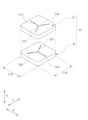
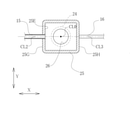
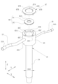
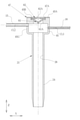
- FIG. 1 It is a schematic diagram which shows the endoscopy using the endoscope for observing the lower gastrointestinal tract and the insertion assist tube for the endoscope. It is a perspective view of the insertion assist tube for an endoscope. It is an exploded perspective view of the insertion assist tube for an endoscope. It is a perspective view which shows the structure of the fluid restraining member. It is explanatory drawing explaining the state in which the insertion part is inserted into the fluid restraining member. It is sectional drawing of the main part which cut the insertion auxiliary tube for an endoscope along the center line. It is sectional drawing of the main part cut along the line VII-VII of FIG.
- the insertion assist tube 10 for endoscopy (hereinafter referred to as the insertion assist tube 10) of the present invention is used for endoscopy for observing the lower gastrointestinal tract such as the large intestine. ..
- the endoscope 2 includes an insertion unit 3, an operation unit 4, and a universal cord 5.
- the insertion portion 3 is inserted transanally into the lower gastrointestinal tract of the subject P, which is the subject.
- the operation unit 4 is continuously provided at the base end portion of the insertion unit 3.
- the universal cord 5 is connected to the operation unit 4.
- the user grasps the operation unit 4 with one hand and the insertion unit 3 with the other hand, and inserts the insertion unit 3 into the body of the subject P through the insertion assist tube 10.
- the subject P wears, for example, an inspection garment having an opening or a notch formed on the back surface.
- the patient is inspected in the lateral decubitus position (lying sideways) on the inspection table T.
- the universal cord 5 is connected to an external device such as a processor device 11 or a light source device 12 via a connector 5A.
- the processor device 11 is electrically connected to the display 13 and the UI (User InterFace) 14.
- the UI 14 has a keyboard, a mouse, a touch pad, a microphone, and the like, and receives an input operation of the user, the doctor D.
- an observation window and an illumination window are provided on the tip surface of the insertion portion 3.
- An image sensor (not shown) and the like are arranged behind the observation window, and an optical fiber cable (not shown) is arranged behind the illumination window.
- the signal line of the image sensor and the optical fiber cable are connected to the processor device 11 and the light source device 12, respectively, through the insertion unit 3, the operation unit 4, and the universal cord 5.
- the processor device 11 performs image processing or the like on the endoscope image captured by the image sensor and displays it on the display 13.
- the insertion assist tube 10 includes an insertion assist tube main body 21, a fluid restraining member 22, a retaining member 23, a suction tube 15, and a liquid feeding tube 16.
- the suction tube 15 and the liquid feed tube 16 correspond to the connection tube within the scope of the claims.
- the suction tube 15 is connected to the suction device 17 via the connection connector 15A.
- the suction device 17 is operated by the operation of the doctor D or a caregiver to generate a negative pressure.
- the suction device 17 may be a drain that sucks manually by a doctor D or a caregiver, or may be a suction pump that automatically generates a negative pressure.
- the liquid feeding tube 16 is connected to the liquid feeding device 18 via the connector 16A. By operating the liquid feeding device 18, the cleaning liquid is fed to the inside of the insertion assisting tube 10 through the liquid feeding tube 16.
- a liquid feeding device similar to that for feeding liquid to the endoscope 2 is used, such as a liquid feeding pump.
- the insertion auxiliary tube main body 21 is provided with a tubular portion 24 and a flange portion 25 integrally.
- the insertion assist tube body 21 is made of a soft material such as a transparent or translucent soft resin.
- the tubular portion 24 is a portion to be inserted into the anus of the subject P when the insertion portion 3 of the endoscope 2 is inserted into the subject P by transanus.
- the tubular portion 24 has a circular cross section so that it can be easily inserted into the anus. Not limited to these, the cross section of the tubular portion 24 may be elliptical.
- the flange portion 25 is continuously provided at the base end of the tubular portion 24 and is formed in a box shape.
- the end of the subject P located outside the body is the base end of the insertion direction Z
- the end of the subject P located inside the body is the insertion direction Z. Called the tip of.
- the pipeline 26 is a through hole arranged along the insertion direction Z and having a circular or elliptical cross section.
- the flange portion 25 has a box shape with the base end 25A open.
- the base end 25A is formed in a rectangular shape, and the opening 25B is formed.
- the opening 25B is a quadrangular opening formed according to the outer shape of the first and second porous members 31 and 32 described later.
- the direction parallel to one side of the quadrangle constituting the opening 25B will be referred to as the left-right direction X
- the direction parallel to the other side constituting the opening 25B and orthogonal to the left-right direction X will be described as the front-back direction Y.
- the insertion direction Z is a direction orthogonal to the left-right direction X and the front-back direction Y, and is parallel to the center line CL0 (see FIG. 6) of the tubular portion 24.
- a fitting hole 25C into which a fitting pin 23B, which will be described later, is fitted is formed around the opening 25B.
- the opening 25B is provided with a fluid restraining member 22.
- the fluid suppressing member 22 suppresses the passage of fluid in the conduit 26 leading to the body of the subject P.
- the fluid restraining member 22 allows gas such as air to pass through and blocks liquids such as body fluids and droplets.
- the fluid suppression member 22 is composed of a first porous member 31 and a second porous member 32, and three slits are arranged in a Y shape.
- the first porous member 31 has three first slits 31A to 31C.
- the first porous member 31 is formed by forming a flexible porous material into a quadrangular plate shape.
- the first slits 31A to 31C are arranged in a Y shape. More specifically, the first slits 31A to 31C are arranged at equal angle intervals of 120 ° and are connected at the center of the first porous member 31.
- one first slit 31A is orthogonal to one side of the first porous member 31, that is, orthogonal to the left-right direction X and is arranged parallel to the front-back direction Y.
- the second porous member 32 is formed of a flexible porous material in the shape of a quadrangular plate.
- the second porous member 32 has three second slits 32A to 32C.
- the second slits 32A to 32C are formed in a direction parallel to the insertion direction Z and intersecting the first slits 31A to 31C.
- the second porous member 32 is the same as the first porous member 31 and is arranged by rotating it by 180 ° around a central axis parallel to the insertion direction Z.
- the second slits 32A to 32C are arranged at equal angle intervals of 120 ° and are connected at the center of the second porous member 32.
- the second slits 32A to 32C are arranged at positions rotated by 180 ° around the central axis parallel to the insertion direction Z with respect to the first slits 31A to 31C.
- one second slit 32A is orthogonal to one side of the second porous member 32, that is, orthogonal to the left-right direction X, and is arranged parallel to the front-back direction Y.
- the porous material forming the first and second porous members 31, 32 is a porous material having a pore size and a structure that allows gas such as air to pass through and blocks liquids such as body fluids and droplets, for example.
- a synthetic sponge formed by foaming a resin or a natural sponge such as corpus cavernosum is used.
- the first porous member 31 and the second porous member 32 may be formed separately, rotated by 180 ° around the central axis parallel to the insertion direction Z, and adhered to be integrated. In this way, cost reduction can be achieved by using two of the same porous members.
- the insertion portion 3 when the insertion portion 3 is inserted into the fluid restraining member 22, the insertion portion 3 is in close contact with the first slits 31A to 31C and the second slits 32A to 32C while the outer peripheral surface of the insertion portion 3 is in close contact with the first slits 31A to 31C.
- gaps 31G and 32G are formed in a part of the first slits 31A to 31C and the second slits 32A to 32C.
- the second slit 32A is formed with respect to the first slits 31A to 31C.
- first porous member 31 and the second porous member 32 are provided with three first slits 31A to 31C and second slits 32A to 32C, respectively, instead of one slit each. It is possible to insert the insertion portion 3 with a smaller resistance than when one slit is provided, and further, there is a gap from the small diameter insertion portion 3 having a diameter of about 3 mm to the large diameter insertion portion 3 having a diameter of about 16 mm. It can be inserted with a small resistance. As a result, the first porous member 31 and the second porous member 32 can be formed from a dense (less void) porous material, and leakage of body fluids and droplets can be further suppressed.
- the outer shape of the fluid restraining member 22, that is, the lengths LX0 and LY0 of each side of the first and second porous members 31 and 32 (see FIG. 4) is larger than the outer diameter R10 of the tubular portion 24. Is preferable. As a result, the fluid suppressing member 22 can sufficiently suppress the passage of the fluid.
- the flange portion 25 is arranged at a position where the center line CL0 of the tubular portion 24 and the center line CL1 of the flange portion 25 coincide with each other in the left-right direction X and the front-rear direction Y.
- the flange portion 25 has lengths LX1 and LY1 (see FIG. 3) in the left-right direction X and the front-rear direction Y larger than the outer diameter R10 of the tubular portion 24 and protrudes from the outer peripheral surface of the tubular portion 24.
- the inner diameter R11 of the pipeline 26 is formed according to the outer diameter of the insertion portion 3, and is preferably 15 mm, for example. Further, the dimensions of the flange portion 25 are preferably 30 mm to 50 mm for the lengths LX1 and LY1 in the left-right direction X and the front-back direction Y, and preferably 20 to 50 mm for the length LZ1 in the insertion direction.
- a partition plate 25D and a storage portion 25E are formed inside the flange portion 25.
- the storage portion 25E is located on the distal end side in the insertion direction Z with respect to the fluid restraining member 22, that is, at a position closer to the body of the subject P than the opening 25B when the tubular portion 24 is inserted into the anus.
- the storage portion 25E constitutes a part of the pipeline 26 through which the insertion portion 3 is inserted, and the dimensions in the left-right direction X and the front-rear direction Y are larger than the inner diameter R11 of the pipeline 26.
- the storage unit 25E is supplied with a cleaning liquid such as water via the liquid feeding tube 16 by operating the liquid feeding device 18.
- the partition plate 25D partitions between the opening 25B and the storage portion 25E.
- the partition plate 25D is formed with a through hole 25F through which the insertion portion 3 is inserted.
- the through hole 25F communicates with the inside of the opening 25B and the storage portion 25E.
- the retaining member 23 is formed in the shape of a quadrangular frame.
- the retaining member 23 is formed according to the outer shape of the flange portion 25 and is fixed to the base end 25A of the flange portion 25.
- the retaining member 23 has a through hole 23A and four fitting pins 23B (see FIG. 3).
- the through hole 23A exposes the first slits 31A to 31C of the first porous member 31.
- the opening 25B of the flange portion 25 and the outer peripheral surfaces of the first and second porous members 31 and 32 are fitted to each other, and the retaining member 23 and the insertion are inserted.
- the first and second porous members 31, 32 are sandwiched by the auxiliary tube main body 21.
- the first porous member 31 and the second porous member 32 are laminated and provided integrally with the insertion assisting tube main body 21 and the retaining member 23, and the fluid suppressing member 22 is provided on the insertion assisting tube main body 21. Is fixed.
- the insertion auxiliary tube main body 21 and the retaining member 23 are fixed to each other by fitting the fitting pin 23B formed in the retaining member 23 into the fitting hole 25C formed in the flange portion 25.
- the method of fixing the insertion assisting tube main body 21 and the retaining member 23 to each other is not limited to the above method, and for example, the insertion assisting tube main body 21 and the retaining member 23 may be fixed to each other by adhesion or crimping. good. Further, a fitting hole may be formed in the retaining member 23, and a fitting pin may be formed in the flange portion 25 to fit the two.
- the fluid restraint is performed on the flange portion 25 provided on the insertion assist tube main body 21 in a state where the first porous member 31 and the second porous member 32 constituting the fluid restraint member 22 are laminated.
- the member 22 is attached, but the present invention is not limited to this.
- the fluid suppressing member 22 integrally provided is directly fixed to the base end of the tubular portion 24 without providing the flange portion 25 on the insertion assist tube main body 21. May be good.
- a suction tube 15 is connected to one side surface 25G of the flange portion 25, and a liquid feeding tube 16 is connected to a side surface 25H different from the side surface 25G.
- the suction tube 15 and the liquid feeding tube 16 are provided at a position communicating with the storage portion 25E. That is, the suction tube 15 and the liquid feeding tube 16 are located closer to the body of the subject P than the fluid suppressing member 22 when the tubular portion 24 is inserted into the anus.
- the suction tube 15 and the liquid feeding tube 16 extend in a direction parallel to the left-right direction X with respect to the flange portion 25.
- the inner diameter R12 of the suction tube 15 needs to be large enough not to clog the excrement in the intestine, and is preferably 4 mm, for example.
- the inner diameter R13 of the liquid feeding tube 16 may be large enough to supply the cleaning liquid, and is preferably 3 mm, for example.
- the suction tube 15 and the liquid feed tube 16 have different connection positions with respect to the flange portion 25 in the insertion direction Z. Specifically, in the insertion direction Z, when the center line CL3 of the liquid feeding tube 16 is on the tip side of the center line CL2 of the suction tube 15 (see FIG. 6) and the tubular portion 24 is inserted into the anus. It is located near the body of the subject P. Further, the suction tube 15 is arranged at a position as close as possible to the fluid restraining member 22, that is, at a position communicating with the storage portion 25E and in contact with the partition plate 25D.
- the suction tube 15 and the liquid feed tube 16 have different connection positions with respect to the flange portion 25 in the left-right direction X and the same in the front-rear direction Y. That is, the center line CL3 of the liquid feeding tube 16 is arranged at a position rotated by 180 ° around the center line CL0 of the tubular portion 24 with respect to the center line CL2 of the suction tube 15.
- the doctor D Using the insertion assist tube 10, the user, doctor D, will explain the operation when performing endoscopy.
- the doctor D inserts the tubular portion 24 of the insertion assist tube 10 into the anal AH of the subject P.
- the subject P is in a lateral decubitus position with his / her left side facing down on the examination table T (state shown in FIG. 1).
- the insertion assist tube 10 is provided with the flange portion 25, the flange portion 25 stops at a position where the flange portion 25 comes into contact with the body surface of the subject P. That is, it is possible to prevent all of the insertion assist tubes 10 from entering the body of the subject P.
- the doctor D connects the suction tube 15 to the suction device 17 and the liquid feeding tube 16 to the liquid feeding device 18.
- the doctor D inserts the insertion portion 3 of the endoscope 2 from the anal AH into the body of the subject P, for example, the lower gastrointestinal tract such as the large intestine, through the insertion assist tube 10.
- the insertion portion 3 is guided from the first slits 31A to 31C and the second slits 32A to 32C of the first and second porous members 31, 32 to the conduit 26 through the through hole 25F and the storage portion 25E. ..
- Physician D can easily insert the insertion section 3 into the lower gastrointestinal tract through the duct 26, i.e. along the insertion direction Z.
- the second slits 32A to 32C are formed in the direction intersecting the first slits 31A to 31C in the fluid suppressing member 22, so that the second slit is formed. It is possible to prevent body fluids and droplets from leaking from the 32A to 32C and the first slits 31A to 31C. Further, in the case of the fluid suppressing member 22, the three first slits 31A to 31C and the second slits 32A to 32C guide the first porous member 31 and the second porous member 32 to the insertion portion. When inserting 3, it is not necessary to aim at the center, and the insertion can be easily performed.
- the doctor D starts sending the cleaning liquid to the storage portion 25E by operating the liquid feeding device 18.
- the insertion unit 3 can be inserted while cleaning the inside of the pipeline 26.
- the suction device 17 may be operated to suck the body fluid or the like stored inside the storage unit 25E. It is preferable that the liquid feeding by the liquid feeding device 18 and the suction by the suction device 17 are not continuously performed, but are performed at the timing when the doctor D or the caregiver recognizes the contamination due to the body fluid or the like.
- the doctor D is asked.
- the suction device 17 is operated to suck the body fluid or the like stored inside the storage unit 25E.
- the suction tube 15 is arranged at a position as close as possible to the fluid suppression member 22, body fluids and droplets are sucked from the suction tube 15 before reaching the fluid suppression member 22. This makes it possible to further prevent leakage of body fluids and droplets from the fluid suppressing member 22.
- the fluid restraining member is composed of the first and second porous members 31 and 32 in which three slits arranged in a Y shape are formed, but the present invention is limited to this.
- the fluid suppressing member 40 is composed of the first and second porous members 41 and 42 having slits formed one by one.
- the first porous member 41 is formed of a flexible porous material in the shape of a quadrangular plate.
- the first porous member 41 has a first slit 41A.
- the first porous member 41 fits into the opening 25B of the flange portion 25.
- the first slit 41A is formed parallel to the left-right direction X and parallel to the insertion direction Z of the insertion portion 3.
- the second porous member 42 is formed of a flexible porous material in the shape of a quadrangular plate.
- the second porous member 42 has a second slit 42A.
- the second porous member 42 fits into the opening 25B of the flange portion 25.
- the second slit 42A is formed in a direction parallel to the insertion direction Z and intersecting the first slit 41A. More specifically, the second slit 42A is formed parallel to the insertion direction Z and parallel to the front-back direction Y.
- the length of each side of the first and second porous members 41 and 42 is larger than the outer diameter R10 of the tubular portion 24.
- the second porous member 42 may be the same as the first porous member 41 and may be arranged by rotating it by 90 ° around the central axis parallel to the insertion direction Z. In this case, it is preferable that the outer shapes of the first and second porous members 41 and 42 are both square.
- the porous material forming the first and second porous members 41 and 42 is the same as the porous material forming the first and second porous members 31 and 32 of the first embodiment.
- the first porous member 41 and the second porous member 42 may be formed separately, and the second slit 42A may be integrated with the first slit 41A by bonding or the like in a state where the second slit 42A is arranged in the intersecting direction. preferable.
- the opening 25B of the flange portion 25 and the outer peripheral surfaces of the first and second porous members 41 and 42 are fitted to each other as in the first embodiment.
- the first and second porous members 41 and 42 are sandwiched between the retaining member 23 and the insertion assist tube main body 21.
- the fluid suppressing member 40 is fixed to the insertion assist tube main body 21 in a state where the first porous member 41 and the second porous member 42 are laminated.
- the fluid suppression member 40 can be used.
- the passage of fluid can be suppressed, and the leakage of body fluids and droplets can be prevented.
- the fluid suppressing member 40 is formed in the direction in which the second slit 42A intersects with the first slit 41A, so that body fluid and droplets leak out. You can prevent that.
- the flange portion 25 constituting the insertion assist tube main body 21 is formed in a box shape, but the present invention is not limited to this, and the flange portion constituting the insertion auxiliary tube main body 21 is cylindrical. It may be formed in.
- the fluid restraining member 46 provided in the flange portion 45 has a disk shape, and the retaining member 47 has an annular shape. Similar to the flange portion 25 in the first embodiment, the flange portion 45 is connected to the tubular portion 24 and is arranged coaxially with the tubular portion 24.
- the flange portion 45 has a cylindrical shape with the base end 45A open.
- the base end 45A is formed in a circular shape, and the opening 45B is formed.
- the opening 45B is a circular opening formed according to the outer shape of the first and second porous members 48, 49 described later.
- a fitting hole 45C into which a fitting pin 47B, which will be described later, is fitted is formed around the opening 45B.
- the opening 45B is provided with a fluid suppressing member 46. Similar to the fluid suppression member 22 in the first embodiment, the fluid suppression member 46 suppresses the passage of fluid in the conduit 26 leading to the body of the subject P when the tubular portion 24 is inserted into the anus.
- the fluid suppressing member 46 is composed of a first porous member 48 and a second porous member 49.
- the first porous member 48 has three first slits 48A to 48C, and the second porous member 49 has three second slits 49A to 49C.
- the first and second porous members 48 and 49 are formed of a flexible porous material in a disk shape.
- the first slits 48A to 48C and the second slits 49A to 49C are arranged in a Y shape, respectively.
- the outer diameters of the first and second porous members 48 and 49 are preferably larger than the outer diameter R10 of the tubular portion 24.
- the first and second porous members 48 and 49 are made of and functionally different from the first and second porous members 31 and 32 in the first embodiment, except that the outer shape is formed into a disk shape. The same applies, and the description thereof will be omitted.
- the second porous member 49 is the same as the first porous member 48 and is arranged by rotating it by 180 ° around the central axis parallel to the insertion direction Z, and the second slits 49A to 49C are the second slits 49A to 49C. 1
- the slits are arranged at positions rotated by 180 ° around the central axis parallel to the insertion direction Z with respect to the slits 48A to 48C. Similar to the first embodiment, the cost can be reduced by using two of the same porous members.
- the flange portion 45 has an outer diameter R20 larger than the outer diameter R10 of the tubular portion 24 and protrudes from the outer peripheral surface of the tubular portion 24.
- a partition plate and a storage portion are formed inside the flange portion 45 as in the first embodiment, but the flange portion 45 has a circular cross section according to the outer shape of the flange portion 45.
- a suction tube 15 and a liquid feeding tube 16 are connected to the outer peripheral surface 45G of the flange portion 45.
- the suction tube 15 and the liquid feeding tube 16 communicate with the storage portion.
- the flange portion 45 is the same as the flange portion 25 in the first embodiment except that the outer shape and the cross-sectional shape are formed in a circular shape, and the description thereof will be omitted. Further, the arrangement of the suction tube 15 and the liquid feeding tube 16 with respect to the flange portion 25 is the same as that of the first embodiment.
- the retaining member 47 is formed in an annular shape.
- the retaining member 47 is formed according to the outer shape of the flange portion 45 and is fixed to the base end 45A of the flange portion 45.
- the retaining member 47 has a through hole 47A and four fitting pins 47B.
- the through hole 47A exposes the first slits 48A to 48C of the first porous member 48.
- the opening 45B of the flange portion 45 and the outer peripheral surfaces of the first and second porous members 48 and 49 are fitted to each other as in the first embodiment.
- the first and second porous members 48 and 49 are sandwiched between the retaining member 47 and the insertion assist tube main body 21.
- the fluid suppressing member 46 is fixed to the insertion assist tube main body 21 in a state where the first and second porous members 48 and 49 are laminated.
- the insertion assist tube 10 in which the flange portion 45 is formed in a cylindrical shape, when the insertion portion 3 is inserted through the conduit 26 as in the first embodiment, the insertion assist is also performed.
- the fluid suppressing member 46 can suppress the passage of the fluid and prevent the body fluid and the droplets from leaking out.
- the first porous member 31, 48 and the second porous member 32 and 49 are provided with three slits, respectively, but the present invention is not limited to the fourth.
- a slit of one or more may be provided. Even when four or more slits are provided, it is preferable that these slits are arranged at equal intervals and are connected at the center of the first and second porous members.
- a fluid suppressing member made of a porous member provided with slits one by one in the first modification may be combined with a flange portion of the second embodiment.
- FIG. 13 shows the configuration of the fluid restraining member 60 having the duckbill valve 61 and the thin plate member 62.
- the fluid suppression member 60 is attached to the opening 45B of the insertion assist tube main body 21 in a state where the duckbill valve 61 and the thin plate member 62 are laminated.
- the insertion assist tube main body provided with the cylindrical flange portion 45 as in the second embodiment. It is preferable to use 21.
- the arrangement of the suction tube 15 and the liquid feeding tube 16 with respect to the flange portion 45 is the same as in the first and second embodiments.
- the duckbill valve 61 has a well-known configuration and has a plurality of lip portions 61A protruding in the insertion direction Z.
- the duckbill valve 61 is formed of an elastic member such as rubber.
- the duckbill valve 61 is in a closed state in which the lip portions 61A are in close contact with each other due to the elastic force in a state where the insertion portion 3 is not inserted. That is, the passage of the fluid in the fluid suppressing member 60 is suppressed.
- the lip portion 61A is opened against the elastic force, and the insertion portion 3 is allowed to be inserted.
- the thin plate member 62 has a through hole 62A having an inner diameter that matches the outer diameter of the insertion portion 3.
- the thin plate member 62 is formed of an elastic member such as rubber.
- the inner peripheral surface of the through hole 62A is in close contact with the outer peripheral surface of the insertion portion 3 in the state where the insertion portion 3 is inserted. That is, the passage of the fluid in the fluid suppressing member 60 is suppressed.
- the outer diameter of the duckbill valve 61 and the thin plate member 62 is preferably larger than the outer diameter R10 of the tubular portion 24.
- the opening 45B of the flange portion 45 and the outer peripheral surfaces of the duckbill valve 61 and the thin plate member 62 are fitted and prevented from coming off, as in the first embodiment.
- the duckbill valve 61 and the thin plate member 62 are sandwiched between the member 47 and the insertion assist tube main body 21.
- the fluid suppression member 60 is fixed to the insertion assist tube main body 21 in a state where the duckbill valve 61 and the thin plate member 62 are laminated.
- the passage of fluid can be suppressed regardless of whether the insertion portion 3 is inserted through the fluid suppression member 60 or the insertion portion 3 is removed, and the fluid suppression member 60 can be used to suppress the passage of the fluid. It is possible to prevent body fluids and droplets from leaking to the outside from the insertion assist tube.
- the suction tube 15 and the liquid feed tube 16 connected to the flange portions 25 and 45 have the center line CL3 of the liquid feed tube 16 rather than the center line CL2 of the suction tube 15 in the insertion direction Z.
- the present invention is not limited to this, and as shown in FIG. 16, the suction tube 15 and the liquid feeding tube 16 with respect to the flange portion 25 in the insertion direction Z.
- the connection position may be the same.
- FIG. 16 as shown in FIG.
- the suction tube 15 and the liquid feed tube 16 extend in a direction parallel to the left-right direction X with respect to the flange portions 25 and 45, but the present invention is not limited to this and is shown in FIG.
- the suction tube 15 and the liquid feeding tube 16 may be inclined with respect to the flange portions 25 and 45 from the direction orthogonal to the insertion direction Z toward the proximal end side in the insertion direction Z at an inclination angle ⁇ .
- the center line CL3 of the liquid feeding tube 16 is arranged at a position rotated by 180 ° around the center line CL0 of the tubular portion 24 with respect to the center line CL2 of the suction tube 15.
- the present invention is not limited to this, and any position may be different around the center line CL0 of the tubular portion 24.
- the center line CL3 of the liquid feeding tube 16 is the center line of the suction tube 15. It may be arranged at a position rotated by 90 ° around the center line CL0 of the tubular portion 24 with respect to CL2.
Landscapes
- Health & Medical Sciences (AREA)
- Life Sciences & Earth Sciences (AREA)
- Surgery (AREA)
- Biomedical Technology (AREA)
- Medical Informatics (AREA)
- Optics & Photonics (AREA)
- Pathology (AREA)
- Radiology & Medical Imaging (AREA)
- Biophysics (AREA)
- Engineering & Computer Science (AREA)
- Physics & Mathematics (AREA)
- Heart & Thoracic Surgery (AREA)
- Nuclear Medicine, Radiotherapy & Molecular Imaging (AREA)
- Molecular Biology (AREA)
- Animal Behavior & Ethology (AREA)
- General Health & Medical Sciences (AREA)
- Public Health (AREA)
- Veterinary Medicine (AREA)
- Endoscopes (AREA)
- External Artificial Organs (AREA)
Priority Applications (4)
| Application Number | Priority Date | Filing Date | Title |
|---|---|---|---|
| DE112021003537.1T DE112021003537T5 (de) | 2020-08-31 | 2021-08-25 | Einführunterstützungsrohr für Endoskop |
| CN202180053233.6A CN115988979A (zh) | 2020-08-31 | 2021-08-25 | 内窥镜用插入辅助管 |
| JP2022545672A JP7440646B2 (ja) | 2020-08-31 | 2021-08-25 | 内視鏡用挿入補助チューブ |
| US18/175,392 US20230200631A1 (en) | 2020-08-31 | 2023-02-27 | Insertion assist tube for endoscope |
Applications Claiming Priority (2)
| Application Number | Priority Date | Filing Date | Title |
|---|---|---|---|
| JP2020-145855 | 2020-08-31 | ||
| JP2020145855 | 2020-08-31 |
Related Child Applications (1)
| Application Number | Title | Priority Date | Filing Date |
|---|---|---|---|
| US18/175,392 Continuation US20230200631A1 (en) | 2020-08-31 | 2023-02-27 | Insertion assist tube for endoscope |
Publications (1)
| Publication Number | Publication Date |
|---|---|
| WO2022045195A1 true WO2022045195A1 (ja) | 2022-03-03 |
Family
ID=80355326
Family Applications (1)
| Application Number | Title | Priority Date | Filing Date |
|---|---|---|---|
| PCT/JP2021/031161 Ceased WO2022045195A1 (ja) | 2020-08-31 | 2021-08-25 | 内視鏡用挿入補助チューブ |
Country Status (5)
| Country | Link |
|---|---|
| US (1) | US20230200631A1 (https=) |
| JP (1) | JP7440646B2 (https=) |
| CN (1) | CN115988979A (https=) |
| DE (1) | DE112021003537T5 (https=) |
| WO (1) | WO2022045195A1 (https=) |
Citations (5)
| Publication number | Priority date | Publication date | Assignee | Title |
|---|---|---|---|---|
| JPS5614301U (https=) * | 1979-07-10 | 1981-02-06 | ||
| JPH0648684U (ja) * | 1992-12-21 | 1994-07-05 | テルモ株式会社 | 血管導入具 |
| JPH10225430A (ja) * | 1997-02-14 | 1998-08-25 | Asahi Optical Co Ltd | 内視鏡用挿入補助具 |
| JP2010270800A (ja) * | 2009-05-20 | 2010-12-02 | Hakko Co Ltd | ダックビル弁 |
| WO2015022972A1 (ja) * | 2013-08-13 | 2015-02-19 | 株式会社カテラ | 側孔付き導入補助器具 |
Family Cites Families (4)
| Publication number | Priority date | Publication date | Assignee | Title |
|---|---|---|---|---|
| JP2004242877A (ja) * | 2003-02-13 | 2004-09-02 | Olympus Corp | 内視鏡装置 |
| JP3864344B2 (ja) | 2003-12-05 | 2006-12-27 | フジノン株式会社 | 内視鏡の挿入補助具 |
| JP2014090736A (ja) * | 2012-10-31 | 2014-05-19 | Olympus Medical Systems Corp | 内視鏡用先端キャップ装置 |
| JP2014140459A (ja) * | 2013-01-23 | 2014-08-07 | Fujifilm Corp | 内視鏡システム |
-
2021
- 2021-08-25 WO PCT/JP2021/031161 patent/WO2022045195A1/ja not_active Ceased
- 2021-08-25 DE DE112021003537.1T patent/DE112021003537T5/de active Pending
- 2021-08-25 JP JP2022545672A patent/JP7440646B2/ja active Active
- 2021-08-25 CN CN202180053233.6A patent/CN115988979A/zh active Pending
-
2023
- 2023-02-27 US US18/175,392 patent/US20230200631A1/en active Pending
Patent Citations (5)
| Publication number | Priority date | Publication date | Assignee | Title |
|---|---|---|---|---|
| JPS5614301U (https=) * | 1979-07-10 | 1981-02-06 | ||
| JPH0648684U (ja) * | 1992-12-21 | 1994-07-05 | テルモ株式会社 | 血管導入具 |
| JPH10225430A (ja) * | 1997-02-14 | 1998-08-25 | Asahi Optical Co Ltd | 内視鏡用挿入補助具 |
| JP2010270800A (ja) * | 2009-05-20 | 2010-12-02 | Hakko Co Ltd | ダックビル弁 |
| WO2015022972A1 (ja) * | 2013-08-13 | 2015-02-19 | 株式会社カテラ | 側孔付き導入補助器具 |
Also Published As
| Publication number | Publication date |
|---|---|
| JP7440646B2 (ja) | 2024-02-28 |
| JPWO2022045195A1 (https=) | 2022-03-03 |
| DE112021003537T5 (de) | 2023-05-04 |
| CN115988979A (zh) | 2023-04-18 |
| US20230200631A1 (en) | 2023-06-29 |
Similar Documents
| Publication | Publication Date | Title |
|---|---|---|
| TWI437972B (zh) | 用於胃造口導管佈置之內視鏡系統 | |
| JP3473374B2 (ja) | 内視鏡の吸引装置 | |
| JP2021520929A (ja) | 内視鏡検査を無汚染で実行する装置及び方法 | |
| WO2013129827A1 (ko) | 대장내시경 검사 보조 기구 | |
| CN113226150A (zh) | 外套管 | |
| JPH07148105A (ja) | カバー式内視鏡 | |
| CN112741585A (zh) | 一种内窥镜辅助装置 | |
| US8974377B2 (en) | Endoscope forceps plug | |
| US20230061631A1 (en) | Endoscope forceps valve cover | |
| JP2022052257A (ja) | 内視鏡用処置具装置及び内視鏡システム | |
| JP7440646B2 (ja) | 内視鏡用挿入補助チューブ | |
| US20230263247A1 (en) | Examination garment for endoscopy | |
| JP2003284675A (ja) | カバー式内視鏡 | |
| JP4307957B2 (ja) | 超音波内視鏡装置 | |
| JP5686711B2 (ja) | 内視鏡用栓体及びこれを備えた内視鏡 | |
| CN214128498U (zh) | 一种免消毒胃肠镜及内镜鞘 | |
| CN111107777B (zh) | 外套管 | |
| TWI764578B (zh) | 內視鏡隔離套 | |
| WO2021221121A1 (ja) | 内視鏡用マウスピース及びドレープアダプタ並びに内視鏡用マウスピースの廃棄処理方法 | |
| JP2602873Y2 (ja) | 内視鏡カバー方式の内視鏡装置 | |
| JP6697301B2 (ja) | 医療機器 | |
| JP3290006B2 (ja) | カバー式内視鏡 | |
| JP3262912B2 (ja) | 内視鏡カバー方式の内視鏡 | |
| KR100748639B1 (ko) | 삽입박막이 내장된 일회용 삽입부를 구비한 내시경 | |
| JPH08545A (ja) | カバー式内視鏡 |
Legal Events
| Date | Code | Title | Description |
|---|---|---|---|
| 121 | Ep: the epo has been informed by wipo that ep was designated in this application |
Ref document number: 21861618 Country of ref document: EP Kind code of ref document: A1 |
|
| ENP | Entry into the national phase |
Ref document number: 2022545672 Country of ref document: JP Kind code of ref document: A |
|
| 122 | Ep: pct application non-entry in european phase |
Ref document number: 21861618 Country of ref document: EP Kind code of ref document: A1 |