WO2022045195A1 - Insertion assistance tube for endoscope - Google Patents
Insertion assistance tube for endoscope Download PDFInfo
- Publication number
- WO2022045195A1 WO2022045195A1 PCT/JP2021/031161 JP2021031161W WO2022045195A1 WO 2022045195 A1 WO2022045195 A1 WO 2022045195A1 JP 2021031161 W JP2021031161 W JP 2021031161W WO 2022045195 A1 WO2022045195 A1 WO 2022045195A1
- Authority
- WO
- WIPO (PCT)
- Prior art keywords
- tube
- fluid
- endoscope
- subject
- assist tube
- Prior art date
Links
Images


Classifications
-
- A—HUMAN NECESSITIES
- A61—MEDICAL OR VETERINARY SCIENCE; HYGIENE
- A61B—DIAGNOSIS; SURGERY; IDENTIFICATION
- A61B1/00—Instruments for performing medical examinations of the interior of cavities or tubes of the body by visual or photographical inspection, e.g. endoscopes; Illuminating arrangements therefor
- A61B1/00147—Holding or positioning arrangements
- A61B1/00154—Holding or positioning arrangements using guiding arrangements for insertion
-
- A—HUMAN NECESSITIES
- A61—MEDICAL OR VETERINARY SCIENCE; HYGIENE
- A61B—DIAGNOSIS; SURGERY; IDENTIFICATION
- A61B1/00—Instruments for performing medical examinations of the interior of cavities or tubes of the body by visual or photographical inspection, e.g. endoscopes; Illuminating arrangements therefor
- A61B1/00064—Constructional details of the endoscope body
- A61B1/00071—Insertion part of the endoscope body
- A61B1/0008—Insertion part of the endoscope body characterised by distal tip features
-
- A—HUMAN NECESSITIES
- A61—MEDICAL OR VETERINARY SCIENCE; HYGIENE
- A61B—DIAGNOSIS; SURGERY; IDENTIFICATION
- A61B1/00—Instruments for performing medical examinations of the interior of cavities or tubes of the body by visual or photographical inspection, e.g. endoscopes; Illuminating arrangements therefor
- A61B1/31—Instruments for performing medical examinations of the interior of cavities or tubes of the body by visual or photographical inspection, e.g. endoscopes; Illuminating arrangements therefor for the rectum, e.g. proctoscopes, sigmoidoscopes, colonoscopes
-
- A—HUMAN NECESSITIES
- A61—MEDICAL OR VETERINARY SCIENCE; HYGIENE
- A61B—DIAGNOSIS; SURGERY; IDENTIFICATION
- A61B1/00—Instruments for performing medical examinations of the interior of cavities or tubes of the body by visual or photographical inspection, e.g. endoscopes; Illuminating arrangements therefor
- A61B1/012—Instruments for performing medical examinations of the interior of cavities or tubes of the body by visual or photographical inspection, e.g. endoscopes; Illuminating arrangements therefor characterised by internal passages or accessories therefor
- A61B1/015—Control of fluid supply or evacuation
Definitions
- the present invention relates to an insertion assist tube for an endoscope that assists the insertion of an endoscope.
- an insertion assist tube for an endoscope called an overtube or a sliding tube may be used.
- This insertion assist tube for an endoscope has a conduit for inserting an insertion portion.
- the insertion assist tube for an endoscope described in Patent Document 1 has a liquid pool portion that communicates with a pipeline, and a donut-shaped sponge or other fluid leakage preventing means is housed inside the liquid pool portion. There is. As a result, the fluid leakage preventing means and the insertion portion are brought into close contact with each other to prevent the leakage of body fluid.
- the present invention can prevent leakage of body fluids and droplets released from a subject regardless of whether the insertion portion of the endoscope is inserted through the anus of the subject or the insertion portion is removed. It is intended to provide an insertion assist tube for a mirror.
- the insertion assist tube for an endoscope of the present invention includes an insertion assist tube main body and a fluid restraining member provided at an opening and restraining the passage of fluid in a pipeline, and the fluid restraining member is a first porous member. And has a second porous member.
- the insertion assist tube body is an insertion assist tube body that is inserted into the subject when the insertion portion of the endoscope is inserted into the subject transanally, and has a conduit through which the insertion portion is inserted. When inserted into a specimen, it has an opening in the conduit at the end of the subject on the outside of the body.
- the fluid restraining member is provided at the opening and restrains the passage of fluid in the pipeline.
- the first porous member is formed with a first slit parallel to the insertion direction of the insertion portion.
- the second porous member is formed with a second slit that is parallel to the insertion direction and intersects the first slit.
- the number of the first slits formed in the first porous member is three and the number of the second slits formed in the second porous member is three.
- the first porous member and the second porous member are fixed to the opening in a state where the second slit is arranged at a position rotated by 180 ° around the central axis parallel to the insertion direction with respect to the first slit. Is preferable. It is preferable that the first porous member and the second porous member are integrally provided in a laminated state.
- At least one of the connecting tubes is a suction tube that is connected to a suction device as an external device and sucks the liquid in the pipeline.
- the insertion assist tube for an endoscope of the present invention includes an insertion assist tube main body, a fluid suppression member, and a connection tube, and the fluid suppression member has a duckbill valve and a thin plate member, and the duckbill valve and the thin plate member.
- At least one of the connecting tubes is a suction tube that is connected to a suction device as an external device and sucks the liquid in the conduit.
- the duckbill valve maintains the airtightness of the pipeline when the insertion is not inserted.
- the thin plate member has a through hole having an inner diameter that matches the outer diameter of the insertion portion, and maintains the airtightness of the pipeline in a state where the insertion portion is inserted.
- connecting tubes It is preferable to have a plurality of connecting tubes, and it is preferable that at least one of the connecting tubes is a liquid feeding tube that is connected to a liquid feeding device as an external device and supplies liquid into the pipeline.
- the fluid restraining member has a larger size than the outer diameter of the insertion assist tube body.
- the insertion assist tube main body has a tubular portion to be inserted into the anus of the subject and a flange portion connected to the tubular portion, and the flange portion preferably protrudes from the outer peripheral surface of the tubular portion.
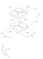
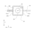
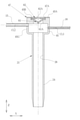
- FIG. 1 It is a schematic diagram which shows the endoscopy using the endoscope for observing the lower gastrointestinal tract and the insertion assist tube for the endoscope. It is a perspective view of the insertion assist tube for an endoscope. It is an exploded perspective view of the insertion assist tube for an endoscope. It is a perspective view which shows the structure of the fluid restraining member. It is explanatory drawing explaining the state in which the insertion part is inserted into the fluid restraining member. It is sectional drawing of the main part which cut the insertion auxiliary tube for an endoscope along the center line. It is sectional drawing of the main part cut along the line VII-VII of FIG.
- the insertion assist tube 10 for endoscopy (hereinafter referred to as the insertion assist tube 10) of the present invention is used for endoscopy for observing the lower gastrointestinal tract such as the large intestine. ..
- the endoscope 2 includes an insertion unit 3, an operation unit 4, and a universal cord 5.
- the insertion portion 3 is inserted transanally into the lower gastrointestinal tract of the subject P, which is the subject.
- the operation unit 4 is continuously provided at the base end portion of the insertion unit 3.
- the universal cord 5 is connected to the operation unit 4.
- the user grasps the operation unit 4 with one hand and the insertion unit 3 with the other hand, and inserts the insertion unit 3 into the body of the subject P through the insertion assist tube 10.
- the subject P wears, for example, an inspection garment having an opening or a notch formed on the back surface.
- the patient is inspected in the lateral decubitus position (lying sideways) on the inspection table T.
- the universal cord 5 is connected to an external device such as a processor device 11 or a light source device 12 via a connector 5A.
- the processor device 11 is electrically connected to the display 13 and the UI (User InterFace) 14.
- the UI 14 has a keyboard, a mouse, a touch pad, a microphone, and the like, and receives an input operation of the user, the doctor D.
- an observation window and an illumination window are provided on the tip surface of the insertion portion 3.
- An image sensor (not shown) and the like are arranged behind the observation window, and an optical fiber cable (not shown) is arranged behind the illumination window.
- the signal line of the image sensor and the optical fiber cable are connected to the processor device 11 and the light source device 12, respectively, through the insertion unit 3, the operation unit 4, and the universal cord 5.
- the processor device 11 performs image processing or the like on the endoscope image captured by the image sensor and displays it on the display 13.
- the insertion assist tube 10 includes an insertion assist tube main body 21, a fluid restraining member 22, a retaining member 23, a suction tube 15, and a liquid feeding tube 16.
- the suction tube 15 and the liquid feed tube 16 correspond to the connection tube within the scope of the claims.
- the suction tube 15 is connected to the suction device 17 via the connection connector 15A.
- the suction device 17 is operated by the operation of the doctor D or a caregiver to generate a negative pressure.
- the suction device 17 may be a drain that sucks manually by a doctor D or a caregiver, or may be a suction pump that automatically generates a negative pressure.
- the liquid feeding tube 16 is connected to the liquid feeding device 18 via the connector 16A. By operating the liquid feeding device 18, the cleaning liquid is fed to the inside of the insertion assisting tube 10 through the liquid feeding tube 16.
- a liquid feeding device similar to that for feeding liquid to the endoscope 2 is used, such as a liquid feeding pump.
- the insertion auxiliary tube main body 21 is provided with a tubular portion 24 and a flange portion 25 integrally.
- the insertion assist tube body 21 is made of a soft material such as a transparent or translucent soft resin.
- the tubular portion 24 is a portion to be inserted into the anus of the subject P when the insertion portion 3 of the endoscope 2 is inserted into the subject P by transanus.
- the tubular portion 24 has a circular cross section so that it can be easily inserted into the anus. Not limited to these, the cross section of the tubular portion 24 may be elliptical.
- the flange portion 25 is continuously provided at the base end of the tubular portion 24 and is formed in a box shape.
- the end of the subject P located outside the body is the base end of the insertion direction Z
- the end of the subject P located inside the body is the insertion direction Z. Called the tip of.
- the pipeline 26 is a through hole arranged along the insertion direction Z and having a circular or elliptical cross section.
- the flange portion 25 has a box shape with the base end 25A open.
- the base end 25A is formed in a rectangular shape, and the opening 25B is formed.
- the opening 25B is a quadrangular opening formed according to the outer shape of the first and second porous members 31 and 32 described later.
- the direction parallel to one side of the quadrangle constituting the opening 25B will be referred to as the left-right direction X
- the direction parallel to the other side constituting the opening 25B and orthogonal to the left-right direction X will be described as the front-back direction Y.
- the insertion direction Z is a direction orthogonal to the left-right direction X and the front-back direction Y, and is parallel to the center line CL0 (see FIG. 6) of the tubular portion 24.
- a fitting hole 25C into which a fitting pin 23B, which will be described later, is fitted is formed around the opening 25B.
- the opening 25B is provided with a fluid restraining member 22.
- the fluid suppressing member 22 suppresses the passage of fluid in the conduit 26 leading to the body of the subject P.
- the fluid restraining member 22 allows gas such as air to pass through and blocks liquids such as body fluids and droplets.
- the fluid suppression member 22 is composed of a first porous member 31 and a second porous member 32, and three slits are arranged in a Y shape.
- the first porous member 31 has three first slits 31A to 31C.
- the first porous member 31 is formed by forming a flexible porous material into a quadrangular plate shape.
- the first slits 31A to 31C are arranged in a Y shape. More specifically, the first slits 31A to 31C are arranged at equal angle intervals of 120 ° and are connected at the center of the first porous member 31.
- one first slit 31A is orthogonal to one side of the first porous member 31, that is, orthogonal to the left-right direction X and is arranged parallel to the front-back direction Y.
- the second porous member 32 is formed of a flexible porous material in the shape of a quadrangular plate.
- the second porous member 32 has three second slits 32A to 32C.
- the second slits 32A to 32C are formed in a direction parallel to the insertion direction Z and intersecting the first slits 31A to 31C.
- the second porous member 32 is the same as the first porous member 31 and is arranged by rotating it by 180 ° around a central axis parallel to the insertion direction Z.
- the second slits 32A to 32C are arranged at equal angle intervals of 120 ° and are connected at the center of the second porous member 32.
- the second slits 32A to 32C are arranged at positions rotated by 180 ° around the central axis parallel to the insertion direction Z with respect to the first slits 31A to 31C.
- one second slit 32A is orthogonal to one side of the second porous member 32, that is, orthogonal to the left-right direction X, and is arranged parallel to the front-back direction Y.
- the porous material forming the first and second porous members 31, 32 is a porous material having a pore size and a structure that allows gas such as air to pass through and blocks liquids such as body fluids and droplets, for example.
- a synthetic sponge formed by foaming a resin or a natural sponge such as corpus cavernosum is used.
- the first porous member 31 and the second porous member 32 may be formed separately, rotated by 180 ° around the central axis parallel to the insertion direction Z, and adhered to be integrated. In this way, cost reduction can be achieved by using two of the same porous members.
- the insertion portion 3 when the insertion portion 3 is inserted into the fluid restraining member 22, the insertion portion 3 is in close contact with the first slits 31A to 31C and the second slits 32A to 32C while the outer peripheral surface of the insertion portion 3 is in close contact with the first slits 31A to 31C.
- gaps 31G and 32G are formed in a part of the first slits 31A to 31C and the second slits 32A to 32C.
- the second slit 32A is formed with respect to the first slits 31A to 31C.
- first porous member 31 and the second porous member 32 are provided with three first slits 31A to 31C and second slits 32A to 32C, respectively, instead of one slit each. It is possible to insert the insertion portion 3 with a smaller resistance than when one slit is provided, and further, there is a gap from the small diameter insertion portion 3 having a diameter of about 3 mm to the large diameter insertion portion 3 having a diameter of about 16 mm. It can be inserted with a small resistance. As a result, the first porous member 31 and the second porous member 32 can be formed from a dense (less void) porous material, and leakage of body fluids and droplets can be further suppressed.
- the outer shape of the fluid restraining member 22, that is, the lengths LX0 and LY0 of each side of the first and second porous members 31 and 32 (see FIG. 4) is larger than the outer diameter R10 of the tubular portion 24. Is preferable. As a result, the fluid suppressing member 22 can sufficiently suppress the passage of the fluid.
- the flange portion 25 is arranged at a position where the center line CL0 of the tubular portion 24 and the center line CL1 of the flange portion 25 coincide with each other in the left-right direction X and the front-rear direction Y.
- the flange portion 25 has lengths LX1 and LY1 (see FIG. 3) in the left-right direction X and the front-rear direction Y larger than the outer diameter R10 of the tubular portion 24 and protrudes from the outer peripheral surface of the tubular portion 24.
- the inner diameter R11 of the pipeline 26 is formed according to the outer diameter of the insertion portion 3, and is preferably 15 mm, for example. Further, the dimensions of the flange portion 25 are preferably 30 mm to 50 mm for the lengths LX1 and LY1 in the left-right direction X and the front-back direction Y, and preferably 20 to 50 mm for the length LZ1 in the insertion direction.
- a partition plate 25D and a storage portion 25E are formed inside the flange portion 25.
- the storage portion 25E is located on the distal end side in the insertion direction Z with respect to the fluid restraining member 22, that is, at a position closer to the body of the subject P than the opening 25B when the tubular portion 24 is inserted into the anus.
- the storage portion 25E constitutes a part of the pipeline 26 through which the insertion portion 3 is inserted, and the dimensions in the left-right direction X and the front-rear direction Y are larger than the inner diameter R11 of the pipeline 26.
- the storage unit 25E is supplied with a cleaning liquid such as water via the liquid feeding tube 16 by operating the liquid feeding device 18.
- the partition plate 25D partitions between the opening 25B and the storage portion 25E.
- the partition plate 25D is formed with a through hole 25F through which the insertion portion 3 is inserted.
- the through hole 25F communicates with the inside of the opening 25B and the storage portion 25E.
- the retaining member 23 is formed in the shape of a quadrangular frame.
- the retaining member 23 is formed according to the outer shape of the flange portion 25 and is fixed to the base end 25A of the flange portion 25.
- the retaining member 23 has a through hole 23A and four fitting pins 23B (see FIG. 3).
- the through hole 23A exposes the first slits 31A to 31C of the first porous member 31.
- the opening 25B of the flange portion 25 and the outer peripheral surfaces of the first and second porous members 31 and 32 are fitted to each other, and the retaining member 23 and the insertion are inserted.
- the first and second porous members 31, 32 are sandwiched by the auxiliary tube main body 21.
- the first porous member 31 and the second porous member 32 are laminated and provided integrally with the insertion assisting tube main body 21 and the retaining member 23, and the fluid suppressing member 22 is provided on the insertion assisting tube main body 21. Is fixed.
- the insertion auxiliary tube main body 21 and the retaining member 23 are fixed to each other by fitting the fitting pin 23B formed in the retaining member 23 into the fitting hole 25C formed in the flange portion 25.
- the method of fixing the insertion assisting tube main body 21 and the retaining member 23 to each other is not limited to the above method, and for example, the insertion assisting tube main body 21 and the retaining member 23 may be fixed to each other by adhesion or crimping. good. Further, a fitting hole may be formed in the retaining member 23, and a fitting pin may be formed in the flange portion 25 to fit the two.
- the fluid restraint is performed on the flange portion 25 provided on the insertion assist tube main body 21 in a state where the first porous member 31 and the second porous member 32 constituting the fluid restraint member 22 are laminated.
- the member 22 is attached, but the present invention is not limited to this.
- the fluid suppressing member 22 integrally provided is directly fixed to the base end of the tubular portion 24 without providing the flange portion 25 on the insertion assist tube main body 21. May be good.
- a suction tube 15 is connected to one side surface 25G of the flange portion 25, and a liquid feeding tube 16 is connected to a side surface 25H different from the side surface 25G.
- the suction tube 15 and the liquid feeding tube 16 are provided at a position communicating with the storage portion 25E. That is, the suction tube 15 and the liquid feeding tube 16 are located closer to the body of the subject P than the fluid suppressing member 22 when the tubular portion 24 is inserted into the anus.
- the suction tube 15 and the liquid feeding tube 16 extend in a direction parallel to the left-right direction X with respect to the flange portion 25.
- the inner diameter R12 of the suction tube 15 needs to be large enough not to clog the excrement in the intestine, and is preferably 4 mm, for example.
- the inner diameter R13 of the liquid feeding tube 16 may be large enough to supply the cleaning liquid, and is preferably 3 mm, for example.
- the suction tube 15 and the liquid feed tube 16 have different connection positions with respect to the flange portion 25 in the insertion direction Z. Specifically, in the insertion direction Z, when the center line CL3 of the liquid feeding tube 16 is on the tip side of the center line CL2 of the suction tube 15 (see FIG. 6) and the tubular portion 24 is inserted into the anus. It is located near the body of the subject P. Further, the suction tube 15 is arranged at a position as close as possible to the fluid restraining member 22, that is, at a position communicating with the storage portion 25E and in contact with the partition plate 25D.
- the suction tube 15 and the liquid feed tube 16 have different connection positions with respect to the flange portion 25 in the left-right direction X and the same in the front-rear direction Y. That is, the center line CL3 of the liquid feeding tube 16 is arranged at a position rotated by 180 ° around the center line CL0 of the tubular portion 24 with respect to the center line CL2 of the suction tube 15.
- the doctor D Using the insertion assist tube 10, the user, doctor D, will explain the operation when performing endoscopy.
- the doctor D inserts the tubular portion 24 of the insertion assist tube 10 into the anal AH of the subject P.
- the subject P is in a lateral decubitus position with his / her left side facing down on the examination table T (state shown in FIG. 1).
- the insertion assist tube 10 is provided with the flange portion 25, the flange portion 25 stops at a position where the flange portion 25 comes into contact with the body surface of the subject P. That is, it is possible to prevent all of the insertion assist tubes 10 from entering the body of the subject P.
- the doctor D connects the suction tube 15 to the suction device 17 and the liquid feeding tube 16 to the liquid feeding device 18.
- the doctor D inserts the insertion portion 3 of the endoscope 2 from the anal AH into the body of the subject P, for example, the lower gastrointestinal tract such as the large intestine, through the insertion assist tube 10.
- the insertion portion 3 is guided from the first slits 31A to 31C and the second slits 32A to 32C of the first and second porous members 31, 32 to the conduit 26 through the through hole 25F and the storage portion 25E. ..
- Physician D can easily insert the insertion section 3 into the lower gastrointestinal tract through the duct 26, i.e. along the insertion direction Z.
- the second slits 32A to 32C are formed in the direction intersecting the first slits 31A to 31C in the fluid suppressing member 22, so that the second slit is formed. It is possible to prevent body fluids and droplets from leaking from the 32A to 32C and the first slits 31A to 31C. Further, in the case of the fluid suppressing member 22, the three first slits 31A to 31C and the second slits 32A to 32C guide the first porous member 31 and the second porous member 32 to the insertion portion. When inserting 3, it is not necessary to aim at the center, and the insertion can be easily performed.
- the doctor D starts sending the cleaning liquid to the storage portion 25E by operating the liquid feeding device 18.
- the insertion unit 3 can be inserted while cleaning the inside of the pipeline 26.
- the suction device 17 may be operated to suck the body fluid or the like stored inside the storage unit 25E. It is preferable that the liquid feeding by the liquid feeding device 18 and the suction by the suction device 17 are not continuously performed, but are performed at the timing when the doctor D or the caregiver recognizes the contamination due to the body fluid or the like.
- the doctor D is asked.
- the suction device 17 is operated to suck the body fluid or the like stored inside the storage unit 25E.
- the suction tube 15 is arranged at a position as close as possible to the fluid suppression member 22, body fluids and droplets are sucked from the suction tube 15 before reaching the fluid suppression member 22. This makes it possible to further prevent leakage of body fluids and droplets from the fluid suppressing member 22.
- the fluid restraining member is composed of the first and second porous members 31 and 32 in which three slits arranged in a Y shape are formed, but the present invention is limited to this.
- the fluid suppressing member 40 is composed of the first and second porous members 41 and 42 having slits formed one by one.
- the first porous member 41 is formed of a flexible porous material in the shape of a quadrangular plate.
- the first porous member 41 has a first slit 41A.
- the first porous member 41 fits into the opening 25B of the flange portion 25.
- the first slit 41A is formed parallel to the left-right direction X and parallel to the insertion direction Z of the insertion portion 3.
- the second porous member 42 is formed of a flexible porous material in the shape of a quadrangular plate.
- the second porous member 42 has a second slit 42A.
- the second porous member 42 fits into the opening 25B of the flange portion 25.
- the second slit 42A is formed in a direction parallel to the insertion direction Z and intersecting the first slit 41A. More specifically, the second slit 42A is formed parallel to the insertion direction Z and parallel to the front-back direction Y.
- the length of each side of the first and second porous members 41 and 42 is larger than the outer diameter R10 of the tubular portion 24.
- the second porous member 42 may be the same as the first porous member 41 and may be arranged by rotating it by 90 ° around the central axis parallel to the insertion direction Z. In this case, it is preferable that the outer shapes of the first and second porous members 41 and 42 are both square.
- the porous material forming the first and second porous members 41 and 42 is the same as the porous material forming the first and second porous members 31 and 32 of the first embodiment.
- the first porous member 41 and the second porous member 42 may be formed separately, and the second slit 42A may be integrated with the first slit 41A by bonding or the like in a state where the second slit 42A is arranged in the intersecting direction. preferable.
- the opening 25B of the flange portion 25 and the outer peripheral surfaces of the first and second porous members 41 and 42 are fitted to each other as in the first embodiment.
- the first and second porous members 41 and 42 are sandwiched between the retaining member 23 and the insertion assist tube main body 21.
- the fluid suppressing member 40 is fixed to the insertion assist tube main body 21 in a state where the first porous member 41 and the second porous member 42 are laminated.
- the fluid suppression member 40 can be used.
- the passage of fluid can be suppressed, and the leakage of body fluids and droplets can be prevented.
- the fluid suppressing member 40 is formed in the direction in which the second slit 42A intersects with the first slit 41A, so that body fluid and droplets leak out. You can prevent that.
- the flange portion 25 constituting the insertion assist tube main body 21 is formed in a box shape, but the present invention is not limited to this, and the flange portion constituting the insertion auxiliary tube main body 21 is cylindrical. It may be formed in.
- the fluid restraining member 46 provided in the flange portion 45 has a disk shape, and the retaining member 47 has an annular shape. Similar to the flange portion 25 in the first embodiment, the flange portion 45 is connected to the tubular portion 24 and is arranged coaxially with the tubular portion 24.
- the flange portion 45 has a cylindrical shape with the base end 45A open.
- the base end 45A is formed in a circular shape, and the opening 45B is formed.
- the opening 45B is a circular opening formed according to the outer shape of the first and second porous members 48, 49 described later.
- a fitting hole 45C into which a fitting pin 47B, which will be described later, is fitted is formed around the opening 45B.
- the opening 45B is provided with a fluid suppressing member 46. Similar to the fluid suppression member 22 in the first embodiment, the fluid suppression member 46 suppresses the passage of fluid in the conduit 26 leading to the body of the subject P when the tubular portion 24 is inserted into the anus.
- the fluid suppressing member 46 is composed of a first porous member 48 and a second porous member 49.
- the first porous member 48 has three first slits 48A to 48C, and the second porous member 49 has three second slits 49A to 49C.
- the first and second porous members 48 and 49 are formed of a flexible porous material in a disk shape.
- the first slits 48A to 48C and the second slits 49A to 49C are arranged in a Y shape, respectively.
- the outer diameters of the first and second porous members 48 and 49 are preferably larger than the outer diameter R10 of the tubular portion 24.
- the first and second porous members 48 and 49 are made of and functionally different from the first and second porous members 31 and 32 in the first embodiment, except that the outer shape is formed into a disk shape. The same applies, and the description thereof will be omitted.
- the second porous member 49 is the same as the first porous member 48 and is arranged by rotating it by 180 ° around the central axis parallel to the insertion direction Z, and the second slits 49A to 49C are the second slits 49A to 49C. 1
- the slits are arranged at positions rotated by 180 ° around the central axis parallel to the insertion direction Z with respect to the slits 48A to 48C. Similar to the first embodiment, the cost can be reduced by using two of the same porous members.
- the flange portion 45 has an outer diameter R20 larger than the outer diameter R10 of the tubular portion 24 and protrudes from the outer peripheral surface of the tubular portion 24.
- a partition plate and a storage portion are formed inside the flange portion 45 as in the first embodiment, but the flange portion 45 has a circular cross section according to the outer shape of the flange portion 45.
- a suction tube 15 and a liquid feeding tube 16 are connected to the outer peripheral surface 45G of the flange portion 45.
- the suction tube 15 and the liquid feeding tube 16 communicate with the storage portion.
- the flange portion 45 is the same as the flange portion 25 in the first embodiment except that the outer shape and the cross-sectional shape are formed in a circular shape, and the description thereof will be omitted. Further, the arrangement of the suction tube 15 and the liquid feeding tube 16 with respect to the flange portion 25 is the same as that of the first embodiment.
- the retaining member 47 is formed in an annular shape.
- the retaining member 47 is formed according to the outer shape of the flange portion 45 and is fixed to the base end 45A of the flange portion 45.
- the retaining member 47 has a through hole 47A and four fitting pins 47B.
- the through hole 47A exposes the first slits 48A to 48C of the first porous member 48.
- the opening 45B of the flange portion 45 and the outer peripheral surfaces of the first and second porous members 48 and 49 are fitted to each other as in the first embodiment.
- the first and second porous members 48 and 49 are sandwiched between the retaining member 47 and the insertion assist tube main body 21.
- the fluid suppressing member 46 is fixed to the insertion assist tube main body 21 in a state where the first and second porous members 48 and 49 are laminated.
- the insertion assist tube 10 in which the flange portion 45 is formed in a cylindrical shape, when the insertion portion 3 is inserted through the conduit 26 as in the first embodiment, the insertion assist is also performed.
- the fluid suppressing member 46 can suppress the passage of the fluid and prevent the body fluid and the droplets from leaking out.
- the first porous member 31, 48 and the second porous member 32 and 49 are provided with three slits, respectively, but the present invention is not limited to the fourth.
- a slit of one or more may be provided. Even when four or more slits are provided, it is preferable that these slits are arranged at equal intervals and are connected at the center of the first and second porous members.
- a fluid suppressing member made of a porous member provided with slits one by one in the first modification may be combined with a flange portion of the second embodiment.
- FIG. 13 shows the configuration of the fluid restraining member 60 having the duckbill valve 61 and the thin plate member 62.
- the fluid suppression member 60 is attached to the opening 45B of the insertion assist tube main body 21 in a state where the duckbill valve 61 and the thin plate member 62 are laminated.
- the insertion assist tube main body provided with the cylindrical flange portion 45 as in the second embodiment. It is preferable to use 21.
- the arrangement of the suction tube 15 and the liquid feeding tube 16 with respect to the flange portion 45 is the same as in the first and second embodiments.
- the duckbill valve 61 has a well-known configuration and has a plurality of lip portions 61A protruding in the insertion direction Z.
- the duckbill valve 61 is formed of an elastic member such as rubber.
- the duckbill valve 61 is in a closed state in which the lip portions 61A are in close contact with each other due to the elastic force in a state where the insertion portion 3 is not inserted. That is, the passage of the fluid in the fluid suppressing member 60 is suppressed.
- the lip portion 61A is opened against the elastic force, and the insertion portion 3 is allowed to be inserted.
- the thin plate member 62 has a through hole 62A having an inner diameter that matches the outer diameter of the insertion portion 3.
- the thin plate member 62 is formed of an elastic member such as rubber.
- the inner peripheral surface of the through hole 62A is in close contact with the outer peripheral surface of the insertion portion 3 in the state where the insertion portion 3 is inserted. That is, the passage of the fluid in the fluid suppressing member 60 is suppressed.
- the outer diameter of the duckbill valve 61 and the thin plate member 62 is preferably larger than the outer diameter R10 of the tubular portion 24.
- the opening 45B of the flange portion 45 and the outer peripheral surfaces of the duckbill valve 61 and the thin plate member 62 are fitted and prevented from coming off, as in the first embodiment.
- the duckbill valve 61 and the thin plate member 62 are sandwiched between the member 47 and the insertion assist tube main body 21.
- the fluid suppression member 60 is fixed to the insertion assist tube main body 21 in a state where the duckbill valve 61 and the thin plate member 62 are laminated.
- the passage of fluid can be suppressed regardless of whether the insertion portion 3 is inserted through the fluid suppression member 60 or the insertion portion 3 is removed, and the fluid suppression member 60 can be used to suppress the passage of the fluid. It is possible to prevent body fluids and droplets from leaking to the outside from the insertion assist tube.
- the suction tube 15 and the liquid feed tube 16 connected to the flange portions 25 and 45 have the center line CL3 of the liquid feed tube 16 rather than the center line CL2 of the suction tube 15 in the insertion direction Z.
- the present invention is not limited to this, and as shown in FIG. 16, the suction tube 15 and the liquid feeding tube 16 with respect to the flange portion 25 in the insertion direction Z.
- the connection position may be the same.
- FIG. 16 as shown in FIG.
- the suction tube 15 and the liquid feed tube 16 extend in a direction parallel to the left-right direction X with respect to the flange portions 25 and 45, but the present invention is not limited to this and is shown in FIG.
- the suction tube 15 and the liquid feeding tube 16 may be inclined with respect to the flange portions 25 and 45 from the direction orthogonal to the insertion direction Z toward the proximal end side in the insertion direction Z at an inclination angle ⁇ .
- the center line CL3 of the liquid feeding tube 16 is arranged at a position rotated by 180 ° around the center line CL0 of the tubular portion 24 with respect to the center line CL2 of the suction tube 15.
- the present invention is not limited to this, and any position may be different around the center line CL0 of the tubular portion 24.
- the center line CL3 of the liquid feeding tube 16 is the center line of the suction tube 15. It may be arranged at a position rotated by 90 ° around the center line CL0 of the tubular portion 24 with respect to CL2.
Landscapes
- Health & Medical Sciences (AREA)
- Life Sciences & Earth Sciences (AREA)
- Surgery (AREA)
- Biomedical Technology (AREA)
- Medical Informatics (AREA)
- Optics & Photonics (AREA)
- Pathology (AREA)
- Radiology & Medical Imaging (AREA)
- Biophysics (AREA)
- Engineering & Computer Science (AREA)
- Physics & Mathematics (AREA)
- Heart & Thoracic Surgery (AREA)
- Nuclear Medicine, Radiotherapy & Molecular Imaging (AREA)
- Molecular Biology (AREA)
- Animal Behavior & Ethology (AREA)
- General Health & Medical Sciences (AREA)
- Public Health (AREA)
- Veterinary Medicine (AREA)
- Endoscopes (AREA)
- External Artificial Organs (AREA)
Abstract
Provided is an insertion assistance tube for an endoscope with which it is possible to prevent leakage of body fluids and droplets discharged from a subject under test even when an insertion section of an endoscope is inserted from the anus of the subject under test or when the insertion section is removed. This insertion assistance tube (10) for an endoscope comprises an insertion assistance tube body (21) and a fluid-suppressing member (22). The insertion assistance tube body (21) has a pipe channel (26) into which an insertion section (3) is inserted, and an opening (25B). The fluid-suppressing member (22) is provided to the opening (25B) and suppresses the passage of fluids. The fluid-suppressing member (22) has a first porous member (31) in which a first slit is formed, and a second porous member (32) in which a second slit that intersects the first slit is formed.
Description
本発明は、内視鏡の挿入を補助する内視鏡用挿入補助チューブに関する。
The present invention relates to an insertion assist tube for an endoscope that assists the insertion of an endoscope.
従来、医療分野において、大腸等の下部消化管内に内視鏡の挿入部を挿入して、管内壁面の観察や診断、治療を施す手技が行われている。下部消化管は複雑に屈曲しており、内視鏡の挿入部を単に押し入れていくだけでは挿入部に力が伝わり難く、下部消化管へ挿入しづらい場合がある。
Conventionally, in the medical field, a technique of inserting an endoscope insertion part into the lower gastrointestinal tract such as the large intestine to observe, diagnose, and treat the inner wall surface of the endoscope has been performed. The lower gastrointestinal tract is complicatedly bent, and it may be difficult to insert the endoscope into the lower gastrointestinal tract because the force is not easily transmitted to the insertion part by simply pushing the insertion part of the endoscope.
そこで、下部消化管に挿入部を挿入する際、オーバーチューブ又はスライディングチューブと称される内視鏡用挿入補助チューブを用いることがある。この内視鏡用挿入補助チューブは、挿入部を挿通するための管路を有している。内視鏡用挿入補助チューブを肛門から被検体内に挿入することにより、管路を通して内視鏡の挿入部を容易に下部消化管へ挿入することが可能になる(例えば、特許文献1)。
Therefore, when inserting the insertion part into the lower gastrointestinal tract, an insertion assist tube for an endoscope called an overtube or a sliding tube may be used. This insertion assist tube for an endoscope has a conduit for inserting an insertion portion. By inserting the insertion assist tube for an endoscope into the subject through the anus, the insertion portion of the endoscope can be easily inserted into the lower gastrointestinal tract through the duct (for example, Patent Document 1).
内視鏡用挿入補助チューブの管路を通して内視鏡の挿入部を挿入している際、管路内は、患者の下部消化管と通じているため、腸内の排泄物や血液等の体液が流れ込んでくることがある。特許文献1に記載の内視鏡用挿入補助チューブでは、管路と連通する液溜まり部を有し、液溜まり部の内部にドーナツ状に形成されたスポンジ等の流体漏出防止手段が収納されている。これにより、流体漏出防止手段と挿入部とが密着し、体液の漏出を防止する。
When inserting the insertion part of the endoscope through the tube of the endoscope insertion assist tube, the inside of the tube is connected to the patient's lower gastrointestinal tract, so body fluids such as excrement and blood in the intestine May flow in. The insertion assist tube for an endoscope described in Patent Document 1 has a liquid pool portion that communicates with a pipeline, and a donut-shaped sponge or other fluid leakage preventing means is housed inside the liquid pool portion. There is. As a result, the fluid leakage preventing means and the insertion portion are brought into close contact with each other to prevent the leakage of body fluid.
医療分野では、感染症に対してさらなる予防対策を講じることが望まれている。特に感染症患者の体液が、医師や介助者等の目や口等の粘膜に接触することによる感染、及び感染症患者から放出される飛沫を吸い込むことによって生じる感染を防ぐ対策が重要となっている。
In the medical field, it is desired to take further preventive measures against infectious diseases. In particular, it is important to take measures to prevent infection caused by contact of the body fluids of infectious disease patients with mucous membranes such as eyes and mouth of doctors and caregivers, and infection caused by inhaling droplets released from infectious disease patients. There is.
しかしながら、上記特許文献1記載の内視鏡用挿入補助チューブでは、管路内に挿入部が挿入されている際は、挿入部に対する流体漏出防止手段の密着により体液の漏出を防止できるが、内視鏡用挿入補助チューブから挿入部を抜去した場合に、液体漏出防止手段の開口部が露呈してしまう。よって、患者の体内から放出された体液及び飛沫が、露呈した流体漏出防止手段の開口部を通って、医師や介助者といった患者の周囲にいる者の粘膜に接触する可能性がある。
However, in the insertion assist tube for an endoscope described in Patent Document 1, when the insertion portion is inserted in the conduit, the leakage of the body fluid can be prevented by the close contact of the fluid leakage prevention means with the insertion portion. When the insertion portion is removed from the insertion assist tube for an endoscope, the opening of the liquid leakage preventing means is exposed. Therefore, body fluids and droplets released from the patient's body may come into contact with the mucous membranes of those around the patient, such as doctors and caregivers, through the openings of the exposed fluid leakage prevention means.
本発明は、内視鏡の挿入部を被検体の肛門から挿入する場合、及び挿入部を抜去した場合のいずれにおいても、被検体から放出される体液及び飛沫の漏出を防ぐことができる内視鏡用挿入補助チューブを提供することを目的とする。
The present invention can prevent leakage of body fluids and droplets released from a subject regardless of whether the insertion portion of the endoscope is inserted through the anus of the subject or the insertion portion is removed. It is intended to provide an insertion assist tube for a mirror.
本発明の内視鏡用挿入補助チューブは、挿入補助チューブ本体と、開口部に設けられ、管路における流体の通過を抑制する流体抑制部材とを備え、流体抑制部材は、第1多孔質部材と、第2多孔質部材を有する。挿入補助チューブ本体は、被検体に対し経肛門で内視鏡の挿入部を挿入する際、被検体に挿入される挿入補助チューブ本体であり、挿入部が挿通される管路を有し、被検体内に挿入された場合、管路における、被検体の体外に位置する側の端に設けられた開口部を有する。流体抑制部材は、開口部に設けられ、管路における流体の通過を抑制する。第1多孔質部材は、挿入部の挿入方向と平行な第1スリットが形成されている。第2多孔質部材は、挿入方向と平行、かつ第1スリットと交差する第2スリットが形成されている。
The insertion assist tube for an endoscope of the present invention includes an insertion assist tube main body and a fluid restraining member provided at an opening and restraining the passage of fluid in a pipeline, and the fluid restraining member is a first porous member. And has a second porous member. The insertion assist tube body is an insertion assist tube body that is inserted into the subject when the insertion portion of the endoscope is inserted into the subject transanally, and has a conduit through which the insertion portion is inserted. When inserted into a specimen, it has an opening in the conduit at the end of the subject on the outside of the body. The fluid restraining member is provided at the opening and restrains the passage of fluid in the pipeline. The first porous member is formed with a first slit parallel to the insertion direction of the insertion portion. The second porous member is formed with a second slit that is parallel to the insertion direction and intersects the first slit.
第1多孔質部材に形成された第1スリットは3本であり、第2多孔質部材に形成された第2スリットは3本であることが好ましい。
It is preferable that the number of the first slits formed in the first porous member is three and the number of the second slits formed in the second porous member is three.
第1多孔質部材及び第2多孔質部材は、第1スリットに対して挿入方向と平行な中心軸回りに180°回転させた位置に第2スリットが配された状態で開口部に固定されることが好ましい。第1多孔質部材と第2多孔質部材とが積層された状態で一体に設けられていることが好ましい。
The first porous member and the second porous member are fixed to the opening in a state where the second slit is arranged at a position rotated by 180 ° around the central axis parallel to the insertion direction with respect to the first slit. Is preferable. It is preferable that the first porous member and the second porous member are integrally provided in a laminated state.
挿入補助チューブ本体の、流体抑制部材より被検体に近接する位置であり、かつ被検体の体外に位置する箇所に配され、挿入補助チューブの管路と連通し、外部機器との接続に用いる接続チューブを備えていることが好ましい。
A connection that is located closer to the subject than the fluid restraining member of the insertion assist tube body and is located outside the body of the subject, communicates with the conduit of the insertion assist tube, and is used for connection with an external device. It is preferable to have a tube.
接続チューブの少なくとも1つは、外部機器としての吸引装置と接続され、管路内の液体を吸引する吸引チューブであることが好ましい。
It is preferable that at least one of the connecting tubes is a suction tube that is connected to a suction device as an external device and sucks the liquid in the pipeline.
本発明の内視鏡用挿入補助チューブは、挿入補助チューブ本体と、流体抑制部材と、接続チューブとを備え、流体抑制部材は、ダックビル弁と、薄板部材とを有し、ダックビル弁と薄板部材とが積層された状態で開口部に固定され、接続チューブの少なくとも1つは、外部機器としての吸引装置と接続され、管路内の液体を吸引する吸引チューブである。ダックビル弁は、挿入部が挿通されていない状態において、管路の気密性を維持する。薄板部材は、挿入部の外径に合わせた内径の貫通孔を有し、挿入部が挿通されている状態において、管路の気密性を維持する。
The insertion assist tube for an endoscope of the present invention includes an insertion assist tube main body, a fluid suppression member, and a connection tube, and the fluid suppression member has a duckbill valve and a thin plate member, and the duckbill valve and the thin plate member. At least one of the connecting tubes is a suction tube that is connected to a suction device as an external device and sucks the liquid in the conduit. The duckbill valve maintains the airtightness of the pipeline when the insertion is not inserted. The thin plate member has a through hole having an inner diameter that matches the outer diameter of the insertion portion, and maintains the airtightness of the pipeline in a state where the insertion portion is inserted.
接続チューブを複数備えていることが好ましく、接続チューブの少なくとも1つは、外部機器としての送液装置と接続され、管路内に液体を供給する送液チューブであることが好ましい。
It is preferable to have a plurality of connecting tubes, and it is preferable that at least one of the connecting tubes is a liquid feeding tube that is connected to a liquid feeding device as an external device and supplies liquid into the pipeline.
流体抑制部材は、挿入補助チューブ本体の外径より寸法が大きいことが好ましい。挿入補助チューブ本体は、被検体の肛門に挿入される筒部と、筒部に連設されたフランジ部とを有し、フランジ部は、筒部の外周面から突出していることが好ましい。
It is preferable that the fluid restraining member has a larger size than the outer diameter of the insertion assist tube body. The insertion assist tube main body has a tubular portion to be inserted into the anus of the subject and a flange portion connected to the tubular portion, and the flange portion preferably protrudes from the outer peripheral surface of the tubular portion.
本発明によれば、内視鏡の挿入部を被検体の肛門から挿入する場合、及び挿入部を抜去した場合のいずれにおいても、内視鏡の挿入部を被検体の肛門から挿入する際、体液及び飛沫の漏出を防ぐことができる。
According to the present invention, when the insertion portion of the endoscope is inserted through the anus of the subject, both when the insertion portion of the endoscope is inserted through the anus of the subject and when the insertion portion of the endoscope is removed. It is possible to prevent leakage of body fluids and droplets.
[第1実施形態]
図1に示すように、本発明の内視鏡用挿入補助チューブ10(以下、挿入補助チューブ10と称する。)は、大腸等の下部消化管を観察する内視鏡検査の際に使用される。内視鏡2は、挿入部3と、操作部4と、ユニバーサルコード5とを備えている。挿入部3は、被検体である被検者Pの下部消化管内に経肛門で挿入される。操作部4は、挿入部3の基端部に連設されている。ユニバーサルコード5は、操作部4に接続されている。 [First Embodiment]
As shown in FIG. 1, theinsertion assist tube 10 for endoscopy (hereinafter referred to as the insertion assist tube 10) of the present invention is used for endoscopy for observing the lower gastrointestinal tract such as the large intestine. .. The endoscope 2 includes an insertion unit 3, an operation unit 4, and a universal cord 5. The insertion portion 3 is inserted transanally into the lower gastrointestinal tract of the subject P, which is the subject. The operation unit 4 is continuously provided at the base end portion of the insertion unit 3. The universal cord 5 is connected to the operation unit 4.
図1に示すように、本発明の内視鏡用挿入補助チューブ10(以下、挿入補助チューブ10と称する。)は、大腸等の下部消化管を観察する内視鏡検査の際に使用される。内視鏡2は、挿入部3と、操作部4と、ユニバーサルコード5とを備えている。挿入部3は、被検体である被検者Pの下部消化管内に経肛門で挿入される。操作部4は、挿入部3の基端部に連設されている。ユニバーサルコード5は、操作部4に接続されている。 [First Embodiment]
As shown in FIG. 1, the
なお、図1では、ユーザである医師Dが操作部4を一方の手で、挿入部3を他方の手で把持し、挿入補助チューブ10を通して挿入部3を被検者Pの体内に挿入している状態を表している。被検者Pは、例えば、背面に開口部又は切り込みが形成された検査衣を着衣する。また、検査台Tの上で側臥位(横向きに寝た状態)で検査を受けている。
In FIG. 1, the user, doctor D, grasps the operation unit 4 with one hand and the insertion unit 3 with the other hand, and inserts the insertion unit 3 into the body of the subject P through the insertion assist tube 10. Represents the state of being. The subject P wears, for example, an inspection garment having an opening or a notch formed on the back surface. In addition, the patient is inspected in the lateral decubitus position (lying sideways) on the inspection table T.
ユニバーサルコード5は、コネクタ5Aを介して、プロセッサ装置11や光源装置12等の外部装置に接続される。プロセッサ装置11は、ディスプレイ13及びUI(User InterFace、ユーザーインターフェース)14と電気的に接続される。UI14は、キーボード、マウス、タッチパッド、マイク等を有し、ユーザである医師Dの入力操作を受け付ける。
The universal cord 5 is connected to an external device such as a processor device 11 or a light source device 12 via a connector 5A. The processor device 11 is electrically connected to the display 13 and the UI (User InterFace) 14. The UI 14 has a keyboard, a mouse, a touch pad, a microphone, and the like, and receives an input operation of the user, the doctor D.
挿入部3の先端面には、図示は省略するが観察窓や照明窓が設けられている。観察窓の奥にはイメージセンサ(図示せず)等が配置され、照明窓の奥には光ファイバケーブル(図示せず)が配置されている。イメージセンサの信号線や光ファイバケーブルは、挿入部3、操作部4、及びユニバーサルコード5内を通って、プロセッサ装置11、光源装置12にそれぞれ接続される。プロセッサ装置11は、イメージセンサにより撮像した内視鏡画像に画像処理等を施してディスプレイ13に表示させる。
Although not shown, an observation window and an illumination window are provided on the tip surface of the insertion portion 3. An image sensor (not shown) and the like are arranged behind the observation window, and an optical fiber cable (not shown) is arranged behind the illumination window. The signal line of the image sensor and the optical fiber cable are connected to the processor device 11 and the light source device 12, respectively, through the insertion unit 3, the operation unit 4, and the universal cord 5. The processor device 11 performs image processing or the like on the endoscope image captured by the image sensor and displays it on the display 13.
図2に示すように、挿入補助チューブ10は、挿入補助チューブ本体21と、流体抑制部材22と、抜け止め部材23と、吸引チューブ15と、送液チューブ16とを備える。
なお、吸引チューブ15及び送液チューブ16は、特許請求の範囲における接続チューブに相当する。 As shown in FIG. 2, the insertion assisttube 10 includes an insertion assist tube main body 21, a fluid restraining member 22, a retaining member 23, a suction tube 15, and a liquid feeding tube 16.
Thesuction tube 15 and the liquid feed tube 16 correspond to the connection tube within the scope of the claims.
なお、吸引チューブ15及び送液チューブ16は、特許請求の範囲における接続チューブに相当する。 As shown in FIG. 2, the insertion assist
The
吸引チューブ15は、接続コネクタ15Aを介して吸引装置17に接続される。吸引装置17は、医師Dまたは介助者の操作により作動して負圧を発生する。吸引装置17を作動させることにより、吸引チューブ15を通して、挿入補助チューブ10内部の液体が吸引される。なお、吸引装置17は、医師Dまたは介助者の手動操作により吸引を行うドレンでもよく、自動的に負圧を生じさせる吸引ポンプでもよい。
The suction tube 15 is connected to the suction device 17 via the connection connector 15A. The suction device 17 is operated by the operation of the doctor D or a caregiver to generate a negative pressure. By operating the suction device 17, the liquid inside the insertion assist tube 10 is sucked through the suction tube 15. The suction device 17 may be a drain that sucks manually by a doctor D or a caregiver, or may be a suction pump that automatically generates a negative pressure.
送液チューブ16は、接続コネクタ16Aを介して送液装置18に接続される。送液装置18を作動させることにより、送液チューブ16を通して、挿入補助チューブ10内部に洗浄液が送液される。送液装置18は、例えば、送液ポンプ等、内視鏡2に液体を送液するものと同様の送液装置を用いる。
The liquid feeding tube 16 is connected to the liquid feeding device 18 via the connector 16A. By operating the liquid feeding device 18, the cleaning liquid is fed to the inside of the insertion assisting tube 10 through the liquid feeding tube 16. As the liquid feeding device 18, for example, a liquid feeding device similar to that for feeding liquid to the endoscope 2 is used, such as a liquid feeding pump.
図3に示すように、挿入補助チューブ本体21は、筒部24と、フランジ部25とが一体に設けられている。挿入補助チューブ本体21は、例えば、透明又は半透明な軟質樹脂等の軟質素材から形成されている。筒部24は、被検者Pに対し経肛門で内視鏡2の挿入部3を挿入する際、被検者Pの肛門に挿入される部分である。筒部24は、肛門に挿入しやすいように断面が円形状に形成されている。なお、これらに限らず、筒部24の断面が楕円形状でもよい。
As shown in FIG. 3, the insertion auxiliary tube main body 21 is provided with a tubular portion 24 and a flange portion 25 integrally. The insertion assist tube body 21 is made of a soft material such as a transparent or translucent soft resin. The tubular portion 24 is a portion to be inserted into the anus of the subject P when the insertion portion 3 of the endoscope 2 is inserted into the subject P by transanus. The tubular portion 24 has a circular cross section so that it can be easily inserted into the anus. Not limited to these, the cross section of the tubular portion 24 may be elliptical.
フランジ部25は、筒部24の基端に連設され、箱状に形成されている。以降では、筒部24が肛門に挿入された場合、被検者Pの体外に位置する側の端を挿入方向Zの基端、被検者Pの体内に位置する側の端を挿入方向Zの先端と称する。筒部24及びフランジ部25の内部には、挿入部3が挿通される管路26(図6参照)を有する。管路26は、挿入方向Zに沿って配され、断面が円または楕円形状の貫通孔である。
The flange portion 25 is continuously provided at the base end of the tubular portion 24 and is formed in a box shape. Hereinafter, when the tubular portion 24 is inserted into the anus, the end of the subject P located outside the body is the base end of the insertion direction Z, and the end of the subject P located inside the body is the insertion direction Z. Called the tip of. Inside the tubular portion 24 and the flange portion 25, there is a pipeline 26 (see FIG. 6) through which the insertion portion 3 is inserted. The pipeline 26 is a through hole arranged along the insertion direction Z and having a circular or elliptical cross section.
フランジ部25は、基端25Aが開放された箱状である。基端25Aは四角形状に形成されており、開口部25Bが形成されている。開口部25Bは、後述する第1及び第2多孔質部材31、32の外形に合わせて形成された四角形状の開口部である。以降では、開口部25Bを構成する四角形の一辺と平行な方向を左右方向Xとし、開口部25Bを構成する別の一辺と平行かつ左右方向Xと直交する方向を前後方向Yとして説明する。また、挿入方向Zは、左右方向X及び前後方向Yと直交する方向であり、筒部24の中心線CL0(図6参照)と平行である。開口部25Bの周囲には、後述する嵌合ピン23Bが嵌合する嵌合孔25Cが形成されている。
The flange portion 25 has a box shape with the base end 25A open. The base end 25A is formed in a rectangular shape, and the opening 25B is formed. The opening 25B is a quadrangular opening formed according to the outer shape of the first and second porous members 31 and 32 described later. Hereinafter, the direction parallel to one side of the quadrangle constituting the opening 25B will be referred to as the left-right direction X, and the direction parallel to the other side constituting the opening 25B and orthogonal to the left-right direction X will be described as the front-back direction Y. Further, the insertion direction Z is a direction orthogonal to the left-right direction X and the front-back direction Y, and is parallel to the center line CL0 (see FIG. 6) of the tubular portion 24. A fitting hole 25C into which a fitting pin 23B, which will be described later, is fitted is formed around the opening 25B.
開口部25Bには、流体抑制部材22が設けられている。流体抑制部材22は、筒部24が肛門に挿入された場合、被検者Pの体内に通じる管路26における流体の通過を抑制する。具体的には、流体抑制部材22は、空気等の気体が通過可能とし、かつ体液等の液体及び飛沫を遮断する。流体抑制部材22は、第1多孔質部材31と、第2多孔質部材32とから構成され、3本のスリットをY字状に配置している。
The opening 25B is provided with a fluid restraining member 22. When the tubular portion 24 is inserted into the anus, the fluid suppressing member 22 suppresses the passage of fluid in the conduit 26 leading to the body of the subject P. Specifically, the fluid restraining member 22 allows gas such as air to pass through and blocks liquids such as body fluids and droplets. The fluid suppression member 22 is composed of a first porous member 31 and a second porous member 32, and three slits are arranged in a Y shape.
図4に示すように第1多孔質部材31は、3本の第1スリット31A~31Cを有する。第1多孔質部材31は、柔軟性を有する多孔質材料を四角形の板状に形成したものである。第1スリット31A~31Cは、Y字状に配される。さらに具体的には、第1スリット31A~31Cは、120°の等角度間隔で配され、第1多孔質部材31の中心で繋がっている。第1スリット31A~31Cのうち、1つの第1スリット31Aは、第1多孔質部材31の1つの辺と直交、すなわち、左右方向Xと直交し、前後方向Yと平行に配されている。
As shown in FIG. 4, the first porous member 31 has three first slits 31A to 31C. The first porous member 31 is formed by forming a flexible porous material into a quadrangular plate shape. The first slits 31A to 31C are arranged in a Y shape. More specifically, the first slits 31A to 31C are arranged at equal angle intervals of 120 ° and are connected at the center of the first porous member 31. Of the first slits 31A to 31C, one first slit 31A is orthogonal to one side of the first porous member 31, that is, orthogonal to the left-right direction X and is arranged parallel to the front-back direction Y.
第2多孔質部材32は、柔軟性を有する多孔質材料を四角形の板状に形成したものである。第2多孔質部材32は、3本の第2スリット32A~32Cを有する。第2スリット32A~32Cは、挿入方向Zと平行、かつ第1スリット31A~31Cと交差する方向に形成されている。具体的には、第2多孔質部材32は、第1多孔質部材31と同じものを挿入方向Zと平行な中心軸回りに180°回転させて配置したものである。第2スリット32A~32Cは、第1スリット31A~31Cと同様に、120°の等角度間隔で配され、第2多孔質部材32の中心で繋がっている。これにより、第2スリット32A~32Cは、第1スリット31A~31Cに対して挿入方向Zと平行な中心軸回りに180°回転させた位置に配される。第2スリット32A~32Cのうち、1つの第2スリット32Aは、第2多孔質部材32の1つの辺と直交、すなわち左右方向Xと直交し、前後方向Yと平行に配されている。
The second porous member 32 is formed of a flexible porous material in the shape of a quadrangular plate. The second porous member 32 has three second slits 32A to 32C. The second slits 32A to 32C are formed in a direction parallel to the insertion direction Z and intersecting the first slits 31A to 31C. Specifically, the second porous member 32 is the same as the first porous member 31 and is arranged by rotating it by 180 ° around a central axis parallel to the insertion direction Z. Like the first slits 31A to 31C, the second slits 32A to 32C are arranged at equal angle intervals of 120 ° and are connected at the center of the second porous member 32. As a result, the second slits 32A to 32C are arranged at positions rotated by 180 ° around the central axis parallel to the insertion direction Z with respect to the first slits 31A to 31C. Of the second slits 32A to 32C, one second slit 32A is orthogonal to one side of the second porous member 32, that is, orthogonal to the left-right direction X, and is arranged parallel to the front-back direction Y.
第1及び第2多孔質部材31、32を形成する多孔質材料は、空気等の気体が通過可能とし、かつ体液等の液体及び飛沫を遮断する孔径及び構造を有する多孔質材料であり、例えば樹脂を発泡成形した合成スポンジ、又は海綿体等の天然スポンジを用いる。第1多孔質部材31と第2多孔質部材32とを別々に形成し、挿入方向Zと平行な中心軸回りに180°回転させた状態で、接着して一体にしてもよい。このように、同じ多孔質部材を2つ使用することでコスト低減を図ることができる。
The porous material forming the first and second porous members 31, 32 is a porous material having a pore size and a structure that allows gas such as air to pass through and blocks liquids such as body fluids and droplets, for example. A synthetic sponge formed by foaming a resin or a natural sponge such as corpus cavernosum is used. The first porous member 31 and the second porous member 32 may be formed separately, rotated by 180 ° around the central axis parallel to the insertion direction Z, and adhered to be integrated. In this way, cost reduction can be achieved by using two of the same porous members.
図5に示すように、挿入部3が流体抑制部材22に挿入された場合、第1スリット31A~31C、及び第2スリット32A~32Cに挿入部3の外周面が密着しながら、挿入部3が挿入方向Zに沿って移動する。この際、第1スリット31A~31C、及び第2スリット32A~32Cの一部には隙間31G、32Gが形成されるが、上述したように第1スリット31A~31Cに対して、第2スリット32A~32Cを、挿入方向Zと平行な中心軸回りに180°回転させて配置しているので、隙間31G、32Gの位置は重ならない。よって、隙間31G、32Gから体液及び飛沫が漏出することを防ぐことができる。
As shown in FIG. 5, when the insertion portion 3 is inserted into the fluid restraining member 22, the insertion portion 3 is in close contact with the first slits 31A to 31C and the second slits 32A to 32C while the outer peripheral surface of the insertion portion 3 is in close contact with the first slits 31A to 31C. Moves along the insertion direction Z. At this time, gaps 31G and 32G are formed in a part of the first slits 31A to 31C and the second slits 32A to 32C. As described above, the second slit 32A is formed with respect to the first slits 31A to 31C. Since ~ 32C is rotated by 180 ° around the central axis parallel to the insertion direction Z, the positions of the gaps 31G and 32G do not overlap. Therefore, it is possible to prevent body fluids and droplets from leaking from the gaps 31G and 32G.
さらに、第1多孔質部材31と第2多孔質部材32に対して、一本ずつのスリットではなく、それぞれ3本の第1スリット31A~31C、及び第2スリット32A~32Cを設けたことで、1本ずつのスリットを設けた場合よりも小さい抵抗で挿入部3を挿入することが可能となり、さらに、直径3mm程度の小径の挿入部3から直径16mm程度の大径の挿入部3まで隙間なく、小さい抵抗で挿入することができる。これにより、密度の高い(空隙の少ない)多孔質材料から第1多孔質部材31と第2多孔質部材32を形成することが可能となり、体液及び飛沫の漏出をさらに抑制することができる。
Further, the first porous member 31 and the second porous member 32 are provided with three first slits 31A to 31C and second slits 32A to 32C, respectively, instead of one slit each. It is possible to insert the insertion portion 3 with a smaller resistance than when one slit is provided, and further, there is a gap from the small diameter insertion portion 3 having a diameter of about 3 mm to the large diameter insertion portion 3 having a diameter of about 16 mm. It can be inserted with a small resistance. As a result, the first porous member 31 and the second porous member 32 can be formed from a dense (less void) porous material, and leakage of body fluids and droplets can be further suppressed.
また、流体抑制部材22の外形、すなわち、第1及び第2多孔質部材31、32の各辺の長さLX0、LY0(図4参照)は、筒部24の外径R10より寸法が大きいことが好ましい。これにより、流体抑制部材22は、流体の通過を十分に抑制することができる。
Further, the outer shape of the fluid restraining member 22, that is, the lengths LX0 and LY0 of each side of the first and second porous members 31 and 32 (see FIG. 4) is larger than the outer diameter R10 of the tubular portion 24. Is preferable. As a result, the fluid suppressing member 22 can sufficiently suppress the passage of the fluid.
図6に示すように、左右方向X及び前後方向Yにおいて、筒部24の中心線CL0と、フランジ部25の中心線CL1とが一致する位置に、フランジ部25が配されている。フランジ部25は、左右方向X及び前後方向Yの長さLX1、LY1(図3参照)が、筒部24の外径R10よりも大きく、筒部24の外周面から突出している。これにより、筒部24が肛門に挿入された場合、フランジ部25が被検者Pの体表面に当接する。よって、挿入補助チューブ10は、フランジ部25が被検者Pの体表面に当接する位置で停止する。フランジ部25は、筒部24が肛門に挿入された場合、被検者Pの体外に位置する。
As shown in FIG. 6, the flange portion 25 is arranged at a position where the center line CL0 of the tubular portion 24 and the center line CL1 of the flange portion 25 coincide with each other in the left-right direction X and the front-rear direction Y. The flange portion 25 has lengths LX1 and LY1 (see FIG. 3) in the left-right direction X and the front-rear direction Y larger than the outer diameter R10 of the tubular portion 24 and protrudes from the outer peripheral surface of the tubular portion 24. As a result, when the tubular portion 24 is inserted into the anus, the flange portion 25 comes into contact with the body surface of the subject P. Therefore, the insertion assist tube 10 stops at a position where the flange portion 25 comes into contact with the body surface of the subject P. The flange portion 25 is located outside the body of the subject P when the tubular portion 24 is inserted into the anus.
なお、管路26の内径R11は、挿入部3の外径に合わせて形成されており、例えば15mmであることが好ましい。また、フランジ部25の寸法は、左右方向X及び前後方向Yの長さLX1、LY1が30mm~50mmであることが好ましく、挿入方向の長さLZ1が20~50mmであることが好ましい。
The inner diameter R11 of the pipeline 26 is formed according to the outer diameter of the insertion portion 3, and is preferably 15 mm, for example. Further, the dimensions of the flange portion 25 are preferably 30 mm to 50 mm for the lengths LX1 and LY1 in the left-right direction X and the front-back direction Y, and preferably 20 to 50 mm for the length LZ1 in the insertion direction.
フランジ部25の内部には、開口部25Bの他に、仕切り板25D、及び貯留部25Eが形成されている。貯留部25Eは、流体抑制部材22よりも挿入方向Zにおける先端側、すなわち、筒部24が肛門に挿入された場合、開口部25Bよりも被検者Pの体内に近接する位置にある。貯留部25Eは、挿入部3が挿通される管路26の一部を構成し、かつ管路26の内径R11よりも左右方向X及び前後方向Yの寸法が大きくなっている。このため、筒部24が肛門に挿入された場合、被検者Pの体内から放出された腸内の排泄物や血液等の体液が流れ込んでくる。また、貯留部25Eは、送液装置18を作動させることにより、送液チューブ16を介して、例えば、水等の洗浄液が供給される。
In addition to the opening 25B, a partition plate 25D and a storage portion 25E are formed inside the flange portion 25. The storage portion 25E is located on the distal end side in the insertion direction Z with respect to the fluid restraining member 22, that is, at a position closer to the body of the subject P than the opening 25B when the tubular portion 24 is inserted into the anus. The storage portion 25E constitutes a part of the pipeline 26 through which the insertion portion 3 is inserted, and the dimensions in the left-right direction X and the front-rear direction Y are larger than the inner diameter R11 of the pipeline 26. Therefore, when the tubular portion 24 is inserted into the anus, body fluids such as intestinal excrement and blood released from the body of the subject P flow into the body. Further, the storage unit 25E is supplied with a cleaning liquid such as water via the liquid feeding tube 16 by operating the liquid feeding device 18.
仕切り板25Dは、開口部25Bと貯留部25Eとの間を仕切っている。開口部25Bと、第1及び第2多孔質部材31、32の外周面とが嵌合した場合、第2多孔質部材32の端面が仕切り板25Dと当接する。仕切り板25Dには、挿入部3が挿通される貫通孔25Fが形成されている。貫通孔25Fは、開口部25Bの内部及び貯留部25Eと連通している。
The partition plate 25D partitions between the opening 25B and the storage portion 25E. When the opening 25B and the outer peripheral surfaces of the first and second porous members 31 and 32 are fitted, the end surface of the second porous member 32 comes into contact with the partition plate 25D. The partition plate 25D is formed with a through hole 25F through which the insertion portion 3 is inserted. The through hole 25F communicates with the inside of the opening 25B and the storage portion 25E.
抜け止め部材23は、四角形の枠状に形成されている。抜け止め部材23は、フランジ部25の外形に合わせて形成され、フランジ部25の基端25Aに固着される。抜け止め部材23は、貫通孔23Aと、4つの嵌合ピン23B(図3参照)とを有する。貫通孔23Aは、第1多孔質部材31の第1スリット31A~31Cを露呈させる。
The retaining member 23 is formed in the shape of a quadrangular frame. The retaining member 23 is formed according to the outer shape of the flange portion 25 and is fixed to the base end 25A of the flange portion 25. The retaining member 23 has a through hole 23A and four fitting pins 23B (see FIG. 3). The through hole 23A exposes the first slits 31A to 31C of the first porous member 31.
挿入補助チューブ本体21に流体抑制部材22を取り付ける場合、フランジ部25の開口部25Bと、第1及び第2多孔質部材31、32の外周面とを嵌合させ、かつ抜け止め部材23及び挿入補助チューブ本体21により第1及び第2多孔質部材31、32を挟み込む。これにより、第1多孔質部材31と第2多孔質部材32とが積層された状態で、挿入補助チューブ本体21及び抜け止め部材23と一体に設けられ、挿入補助チューブ本体21に流体抑制部材22が固定される。この場合、抜け止め部材23に形成した嵌合ピン23Bを、フランジ部25に形成した嵌合孔25Cに嵌合させることにより挿入補助チューブ本体21と抜け止め部材23とを互いに固着する。
When the fluid restraining member 22 is attached to the insertion assist tube main body 21, the opening 25B of the flange portion 25 and the outer peripheral surfaces of the first and second porous members 31 and 32 are fitted to each other, and the retaining member 23 and the insertion are inserted. The first and second porous members 31, 32 are sandwiched by the auxiliary tube main body 21. As a result, the first porous member 31 and the second porous member 32 are laminated and provided integrally with the insertion assisting tube main body 21 and the retaining member 23, and the fluid suppressing member 22 is provided on the insertion assisting tube main body 21. Is fixed. In this case, the insertion auxiliary tube main body 21 and the retaining member 23 are fixed to each other by fitting the fitting pin 23B formed in the retaining member 23 into the fitting hole 25C formed in the flange portion 25.
なお、挿入補助チューブ本体21と抜け止め部材23とを互いに固着する方法としては上記の方法に限らず、例えば、接着または圧着により挿入補助チューブ本体21と抜け止め部材23とを互いに固着してもよい。また、抜け止め部材23に嵌合孔を形成し、フランジ部25に嵌合ピンを形成して両者を嵌合させてもよい。
The method of fixing the insertion assisting tube main body 21 and the retaining member 23 to each other is not limited to the above method, and for example, the insertion assisting tube main body 21 and the retaining member 23 may be fixed to each other by adhesion or crimping. good. Further, a fitting hole may be formed in the retaining member 23, and a fitting pin may be formed in the flange portion 25 to fit the two.
なお、本実施形態では、流体抑制部材22を構成する第1多孔質部材31と第2多孔質部材32とが積層された状態で、挿入補助チューブ本体21に設けられたフランジ部25に流体抑制部材22が取り付けられているが、これに限らず、例えば、挿入補助チューブ本体21にフランジ部25を設けずに、一体に設けた流体抑制部材22を筒部24の基端に直接固着させてもよい。
In this embodiment, the fluid restraint is performed on the flange portion 25 provided on the insertion assist tube main body 21 in a state where the first porous member 31 and the second porous member 32 constituting the fluid restraint member 22 are laminated. The member 22 is attached, but the present invention is not limited to this. For example, the fluid suppressing member 22 integrally provided is directly fixed to the base end of the tubular portion 24 without providing the flange portion 25 on the insertion assist tube main body 21. May be good.
フランジ部25の1つの側面25Gには、吸引チューブ15が接続され、側面25Gとは異なる側面25Hには、送液チューブ16が接続されている。吸引チューブ15及び送液チューブ16は、貯留部25Eと連通する箇所に設けられている。すなわち、吸引チューブ15及び送液チューブ16は、筒部24が肛門に挿入された場合、流体抑制部材22よりも被検者Pの体内に近接する位置にある。吸引チューブ15と送液チューブ16は、フランジ部25に対して、左右方向Xと平行な方向に延出している。吸引チューブ15の内径R12は、腸内の排泄物等が詰まらない程度の大きさが必要であり、例えば4mmであることが好ましい。送液チューブ16の内径R13は、洗浄液を供給可能な大きさであればよく、例えば3mmであることが好ましい。
A suction tube 15 is connected to one side surface 25G of the flange portion 25, and a liquid feeding tube 16 is connected to a side surface 25H different from the side surface 25G. The suction tube 15 and the liquid feeding tube 16 are provided at a position communicating with the storage portion 25E. That is, the suction tube 15 and the liquid feeding tube 16 are located closer to the body of the subject P than the fluid suppressing member 22 when the tubular portion 24 is inserted into the anus. The suction tube 15 and the liquid feeding tube 16 extend in a direction parallel to the left-right direction X with respect to the flange portion 25. The inner diameter R12 of the suction tube 15 needs to be large enough not to clog the excrement in the intestine, and is preferably 4 mm, for example. The inner diameter R13 of the liquid feeding tube 16 may be large enough to supply the cleaning liquid, and is preferably 3 mm, for example.
吸引チューブ15と送液チューブ16とは、挿入方向Zにおいて、フランジ部25に対する接続位置が互いに異なる。具体的には、挿入方向Zにおいて、吸引チューブ15の中心線CL2(図6参照)よりも、送液チューブ16の中心線CL3が先端側であり、筒部24が肛門に挿入された場合、被検者Pの体内に近い位置にある。さらに、吸引チューブ15は、流体抑制部材22に可能な限り近い位置、すなわち、貯留部25Eと連通し、且つ仕切り板25Dに接する位置に配されている。
The suction tube 15 and the liquid feed tube 16 have different connection positions with respect to the flange portion 25 in the insertion direction Z. Specifically, in the insertion direction Z, when the center line CL3 of the liquid feeding tube 16 is on the tip side of the center line CL2 of the suction tube 15 (see FIG. 6) and the tubular portion 24 is inserted into the anus. It is located near the body of the subject P. Further, the suction tube 15 is arranged at a position as close as possible to the fluid restraining member 22, that is, at a position communicating with the storage portion 25E and in contact with the partition plate 25D.
図7に示すように、吸引チューブ15と送液チューブ16とは、フランジ部25に対する接続位置が、左右方向Xにおいて異なり、かつ前後方向Yにおいて同じである。すなわち、送液チューブ16の中心線CL3は、吸引チューブ15の中心線CL2に対して、筒部24の中心線CL0の回りに180°回転させた位置に配される。
As shown in FIG. 7, the suction tube 15 and the liquid feed tube 16 have different connection positions with respect to the flange portion 25 in the left-right direction X and the same in the front-rear direction Y. That is, the center line CL3 of the liquid feeding tube 16 is arranged at a position rotated by 180 ° around the center line CL0 of the tubular portion 24 with respect to the center line CL2 of the suction tube 15.
挿入補助チューブ10を用いて、ユーザである医師Dが、内視鏡検査を行う際の動作について説明する。図8に示すように、先ず、挿入部3を被検者Pに挿入する前の準備として、医師Dは、被検者Pの肛門AHに挿入補助チューブ10の筒部24を挿入する。この場合、被検者Pは、検査台Tの上で自身の左側を下に向けた側臥位となっている(図1に示す状態)。上述したように、挿入補助チューブ10には、フランジ部25が設けられているため、フランジ部25が被検者Pの体表面と当接した位置で停止する。すなわち、挿入補助チューブ10の全てが被検者Pの体内に進入することを防ぐことができる。また、医師Dは、吸引チューブ15を吸引装置17に、送液チューブ16を送液装置18に接続させる。
Using the insertion assist tube 10, the user, doctor D, will explain the operation when performing endoscopy. As shown in FIG. 8, first, as a preparation before inserting the insertion portion 3 into the subject P, the doctor D inserts the tubular portion 24 of the insertion assist tube 10 into the anal AH of the subject P. In this case, the subject P is in a lateral decubitus position with his / her left side facing down on the examination table T (state shown in FIG. 1). As described above, since the insertion assist tube 10 is provided with the flange portion 25, the flange portion 25 stops at a position where the flange portion 25 comes into contact with the body surface of the subject P. That is, it is possible to prevent all of the insertion assist tubes 10 from entering the body of the subject P. Further, the doctor D connects the suction tube 15 to the suction device 17 and the liquid feeding tube 16 to the liquid feeding device 18.
次に、医師Dは、挿入補助チューブ10を通して、内視鏡2の挿入部3を肛門AHから被検者Pの体内、例えば大腸等の下部消化管に挿入する。挿入部3は、第1及び第2多孔質部材31、32の第1スリット31A~31C、及び第2スリット32A~32Cから貫通孔25F、及び貯留部25Eを通って管路26にガイドされる。医師Dは、管路26を通して、すなわち挿入方向Zに沿って挿入部3を容易に下部消化管へ挿入することができる。
Next, the doctor D inserts the insertion portion 3 of the endoscope 2 from the anal AH into the body of the subject P, for example, the lower gastrointestinal tract such as the large intestine, through the insertion assist tube 10. The insertion portion 3 is guided from the first slits 31A to 31C and the second slits 32A to 32C of the first and second porous members 31, 32 to the conduit 26 through the through hole 25F and the storage portion 25E. .. Physician D can easily insert the insertion section 3 into the lower gastrointestinal tract through the duct 26, i.e. along the insertion direction Z.
大腸等の下部消化管に対して内視鏡2で検査を行う場合、送液チューブ16及び内視鏡2を通して送り込まれる空気や洗浄液と一緒に、腸内の排泄物や血液等の体液及び飛沫が放出されることがあるが、上述したように、挿入補助チューブ10では、流体抑制部材22を通して挿入部3を被検者Pの体内に挿入している。これにより、流体抑制部材22が流体の通過を抑制する。よって、挿入補助チューブ10から体液及び飛沫が漏出することを防ぐことができる。
When an examination is performed on the lower gastrointestinal tract such as the large intestine with an endoscope 2, body fluids such as excrement and blood in the intestine and droplets are collected together with the air and washing liquid sent through the liquid delivery tube 16 and the endoscope 2. However, as described above, in the insertion assist tube 10, the insertion portion 3 is inserted into the body of the subject P through the fluid restraining member 22. As a result, the fluid suppressing member 22 suppresses the passage of the fluid. Therefore, it is possible to prevent the body fluid and the droplets from leaking from the insertion assist tube 10.
一方、挿入補助チューブ10から挿入部3を抜去した場合でも、流体抑制部材22では、第2スリット32A~32Cが、第1スリット31A~31Cと交差する方向に形成されているので、第2スリット32A~32C及び第1スリット31A~31Cから体液及び飛沫が漏出することを防ぐことができる。また、流体抑制部材22の場合、3本の第1スリット31A~31C、及び第2スリット32A~32Cが、第1多孔質部材31と第2多孔質部材32の中心にガイドするため、挿入部3を挿入する際、中心を狙う必要が無く、挿入を容易に行うことができる。
On the other hand, even when the insertion portion 3 is removed from the insertion assist tube 10, the second slits 32A to 32C are formed in the direction intersecting the first slits 31A to 31C in the fluid suppressing member 22, so that the second slit is formed. It is possible to prevent body fluids and droplets from leaking from the 32A to 32C and the first slits 31A to 31C. Further, in the case of the fluid suppressing member 22, the three first slits 31A to 31C and the second slits 32A to 32C guide the first porous member 31 and the second porous member 32 to the insertion portion. When inserting 3, it is not necessary to aim at the center, and the insertion can be easily performed.
また、内視鏡検査中に、体液等による汚れを視認した場合、医師Dは、送液装置18を作動させることにより、貯留部25Eへの洗浄液の送液を開始する。貯留部25E内に洗浄液を送り込むことで、管路26の内部を洗浄しながら、挿入部3の挿入を行うことができる。なお、この際、吸引装置17を作動させて貯留部25Eの内部に貯留された体液等を吸引させてもよい。送液装置18による送液、及び吸引装置17による吸引は、継続的には行わず、医師D又は介助者が体液等による汚れを認識したタイミングで行うことが好ましい。
Further, when the dirt due to the body fluid or the like is visually recognized during the endoscopy, the doctor D starts sending the cleaning liquid to the storage portion 25E by operating the liquid feeding device 18. By sending the cleaning liquid into the storage unit 25E, the insertion unit 3 can be inserted while cleaning the inside of the pipeline 26. At this time, the suction device 17 may be operated to suck the body fluid or the like stored inside the storage unit 25E. It is preferable that the liquid feeding by the liquid feeding device 18 and the suction by the suction device 17 are not continuously performed, but are performed at the timing when the doctor D or the caregiver recognizes the contamination due to the body fluid or the like.
また、内視鏡2による下部消化管の観察を終えた後、挿入補助チューブ10から挿入部3を抜去する際、あるいは、挿入補助チューブ10から挿入部3を抜去する前に、医師Dは、吸引装置17を作動させて貯留部25Eの内部に貯留された体液等を吸引させる。上述したように、吸引チューブ15は、流体抑制部材22に可能な限り近い位置に配されているため、体液及び飛沫が流体抑制部材22に到達する前に吸引チューブ15から吸引される。これにより、流体抑制部材22から体液及び飛沫の漏出をさらに防ぐことができる。
Further, after the observation of the lower gastrointestinal tract by the endoscope 2 is completed, when the insertion portion 3 is removed from the insertion assist tube 10, or before the insertion portion 3 is removed from the insertion assist tube 10, the doctor D is asked. The suction device 17 is operated to suck the body fluid or the like stored inside the storage unit 25E. As described above, since the suction tube 15 is arranged at a position as close as possible to the fluid suppression member 22, body fluids and droplets are sucked from the suction tube 15 before reaching the fluid suppression member 22. This makes it possible to further prevent leakage of body fluids and droplets from the fluid suppressing member 22.
[第1変形例]
上記第1実施形態では、流体抑制部材として、Y字状に配された3つのスリットが形成された第1及び第2多孔質部材31、32から構成する例を上げているが、これに限らず、図9に示す変形例では、流体抑制部材40として、1つずつのスリットが形成された第1及び第2多孔質部材41、42から構成している。 [First modification]
In the first embodiment, the fluid restraining member is composed of the first and second porous members 31 and 32 in which three slits arranged in a Y shape are formed, but the present invention is limited to this. However, in the modified example shown in FIG. 9, the fluid suppressing member 40 is composed of the first and second porous members 41 and 42 having slits formed one by one.
上記第1実施形態では、流体抑制部材として、Y字状に配された3つのスリットが形成された第1及び第2多孔質部材31、32から構成する例を上げているが、これに限らず、図9に示す変形例では、流体抑制部材40として、1つずつのスリットが形成された第1及び第2多孔質部材41、42から構成している。 [First modification]
In the first embodiment, the fluid restraining member is composed of the first and second
第1多孔質部材41は、柔軟性を有する多孔質材料を四角形の板状に形成したものである。第1多孔質部材41は、第1スリット41Aを有する。第1多孔質部材41は、フランジ部25の開口部25Bと嵌合する。第1スリット41Aは、左右方向Xと平行、かつ挿入部3の挿入方向Zと平行に形成されている。
The first porous member 41 is formed of a flexible porous material in the shape of a quadrangular plate. The first porous member 41 has a first slit 41A. The first porous member 41 fits into the opening 25B of the flange portion 25. The first slit 41A is formed parallel to the left-right direction X and parallel to the insertion direction Z of the insertion portion 3.
図10に示すように、第2多孔質部材42は、柔軟性を有する多孔質材料を四角形の板状に形成したものである。第2多孔質部材42は、第2スリット42Aを有する。第2多孔質部材42は、フランジ部25の開口部25Bと嵌合する。第2スリット42Aは、挿入方向Zと平行、かつ第1スリット41Aと交差する方向に形成されている。さらに詳しくは、第2スリット42Aは、挿入方向Zと平行、かつ前後方向Yと平行に形成されている。このように、第1スリット41Aと第2スリット42Aとが交差しているので、挿入部3に対する隙間の位置が重ならない。また、第1及び第2多孔質部材41、42の各辺の長さは、筒部24の外径R10より寸法が大きいことが好ましい。
As shown in FIG. 10, the second porous member 42 is formed of a flexible porous material in the shape of a quadrangular plate. The second porous member 42 has a second slit 42A. The second porous member 42 fits into the opening 25B of the flange portion 25. The second slit 42A is formed in a direction parallel to the insertion direction Z and intersecting the first slit 41A. More specifically, the second slit 42A is formed parallel to the insertion direction Z and parallel to the front-back direction Y. As described above, since the first slit 41A and the second slit 42A intersect with each other, the positions of the gaps with respect to the insertion portion 3 do not overlap. Further, it is preferable that the length of each side of the first and second porous members 41 and 42 is larger than the outer diameter R10 of the tubular portion 24.
なお、本変形例においては、第2多孔質部材42は、第1多孔質部材41と同じものを挿入方向Zと平行な中心軸回りに90°回転させて配置したものでもよい。この場合、第1及び第2多孔質部材41、42の外形状はともに正方形であることが好ましい。
In this modification, the second porous member 42 may be the same as the first porous member 41 and may be arranged by rotating it by 90 ° around the central axis parallel to the insertion direction Z. In this case, it is preferable that the outer shapes of the first and second porous members 41 and 42 are both square.
第1及び第2多孔質部材41、42を形成する多孔質材料は、上記第1実施形態の第1及び第2多孔質部材31、32を形成する多孔質材料と同様である。第1多孔質部材41と第2多孔質部材42とを別々に形成し、第1スリット41Aに対して第2スリット42Aを、交差する方向に配置した状態で、接着等により一体にすることが好ましい。
The porous material forming the first and second porous members 41 and 42 is the same as the porous material forming the first and second porous members 31 and 32 of the first embodiment. The first porous member 41 and the second porous member 42 may be formed separately, and the second slit 42A may be integrated with the first slit 41A by bonding or the like in a state where the second slit 42A is arranged in the intersecting direction. preferable.
挿入補助チューブ本体21に流体抑制部材40を取り付ける場合、上記第1実施形態と同様に、フランジ部25の開口部25Bと、第1及び第2多孔質部材41、42の外周面とを嵌合させ、かつ抜け止め部材23及び挿入補助チューブ本体21により第1及び第2多孔質部材41、42を挟み込む。これにより、第1多孔質部材41と第2多孔質部材42とが積層された状態で、挿入補助チューブ本体21に流体抑制部材40が固定される。
When the fluid restraining member 40 is attached to the insertion assist tube main body 21, the opening 25B of the flange portion 25 and the outer peripheral surfaces of the first and second porous members 41 and 42 are fitted to each other as in the first embodiment. The first and second porous members 41 and 42 are sandwiched between the retaining member 23 and the insertion assist tube main body 21. As a result, the fluid suppressing member 40 is fixed to the insertion assist tube main body 21 in a state where the first porous member 41 and the second porous member 42 are laminated.
流体抑制部材40が設けられた挿入補助チューブ10を内視鏡検査に用いることで、上記第1実施形態と同様に、管路26を通して挿入部3を挿入している場合、流体抑制部材40が流体の通過を抑制することができ、体液及び飛沫が漏出することを防ぐことができる。また、挿入補助チューブ10から挿入部3を抜去した場合でも、流体抑制部材40は、第1スリット41Aに対して第2スリット42Aが交差する方向に形成されているので、体液及び飛沫が漏出することを防ぐことができる。
By using the insertion assist tube 10 provided with the fluid suppression member 40 for endoscopy, when the insertion portion 3 is inserted through the conduit 26 as in the first embodiment, the fluid suppression member 40 can be used. The passage of fluid can be suppressed, and the leakage of body fluids and droplets can be prevented. Further, even when the insertion portion 3 is removed from the insertion assist tube 10, the fluid suppressing member 40 is formed in the direction in which the second slit 42A intersects with the first slit 41A, so that body fluid and droplets leak out. You can prevent that.
[第2実施形態]
また、上記第1実施形態では、挿入補助チューブ本体21を構成するフランジ部25が、箱状に形成されているが、これに限らず、挿入補助チューブ本体21を構成するフランジ部が、円筒形状に形成されていてもよい。図11に示すように、本実施形態においては、フランジ部45に設けられる流体抑制部材46は円板状であり、抜け止め部材47は、円環状である。フランジ部45は、上記第1実施形態におけるフランジ部25と同様に、筒部24に連設され、かつ筒部24と同軸上に配されている。 [Second Embodiment]
Further, in the first embodiment, theflange portion 25 constituting the insertion assist tube main body 21 is formed in a box shape, but the present invention is not limited to this, and the flange portion constituting the insertion auxiliary tube main body 21 is cylindrical. It may be formed in. As shown in FIG. 11, in the present embodiment, the fluid restraining member 46 provided in the flange portion 45 has a disk shape, and the retaining member 47 has an annular shape. Similar to the flange portion 25 in the first embodiment, the flange portion 45 is connected to the tubular portion 24 and is arranged coaxially with the tubular portion 24.
また、上記第1実施形態では、挿入補助チューブ本体21を構成するフランジ部25が、箱状に形成されているが、これに限らず、挿入補助チューブ本体21を構成するフランジ部が、円筒形状に形成されていてもよい。図11に示すように、本実施形態においては、フランジ部45に設けられる流体抑制部材46は円板状であり、抜け止め部材47は、円環状である。フランジ部45は、上記第1実施形態におけるフランジ部25と同様に、筒部24に連設され、かつ筒部24と同軸上に配されている。 [Second Embodiment]
Further, in the first embodiment, the
図12に示すように、フランジ部45は、基端45Aが開放された円筒形状である。基端45Aは円形状に形成されており、開口部45Bが形成されている。開口部45Bは、後述する第1及び第2多孔質部材48、49の外形に合わせて形成された円形状の開口部である。開口部45Bの周囲には、後述する嵌合ピン47Bが嵌合する嵌合孔45Cが形成されている。
As shown in FIG. 12, the flange portion 45 has a cylindrical shape with the base end 45A open. The base end 45A is formed in a circular shape, and the opening 45B is formed. The opening 45B is a circular opening formed according to the outer shape of the first and second porous members 48, 49 described later. A fitting hole 45C into which a fitting pin 47B, which will be described later, is fitted is formed around the opening 45B.
開口部45Bには、流体抑制部材46が設けられている。流体抑制部材46は、上記第1実施形態における流体抑制部材22と同様に、筒部24が肛門に挿入された場合、被検者Pの体内に通じる管路26における流体の通過を抑制する。流体抑制部材46は、第1多孔質部材48と、第2多孔質部材49とから構成されている。
The opening 45B is provided with a fluid suppressing member 46. Similar to the fluid suppression member 22 in the first embodiment, the fluid suppression member 46 suppresses the passage of fluid in the conduit 26 leading to the body of the subject P when the tubular portion 24 is inserted into the anus. The fluid suppressing member 46 is composed of a first porous member 48 and a second porous member 49.
第1多孔質部材48は、3本の第1スリット48A~48Cを有し、第2多孔質部材49は、3本の第2スリット49A~49Cを有する。第1及び第2多孔質部材48、49は、柔軟性を有する多孔質材料を円板状に形成したものである。第1スリット48A~48C、第2スリット49A~49Cは、それぞれY字状に配される。第1及び第2多孔質部材48、49の外径は、筒部24の外径R10より寸法が大きいことが好ましい。なお、第1及び第2多孔質部材48、49は、外形を円板状に形成したこと以外は、上記第1実施形態における第1及び第2多孔質部材31、32と材質及び機能的に同様であり、説明を省略する。
The first porous member 48 has three first slits 48A to 48C, and the second porous member 49 has three second slits 49A to 49C. The first and second porous members 48 and 49 are formed of a flexible porous material in a disk shape. The first slits 48A to 48C and the second slits 49A to 49C are arranged in a Y shape, respectively. The outer diameters of the first and second porous members 48 and 49 are preferably larger than the outer diameter R10 of the tubular portion 24. The first and second porous members 48 and 49 are made of and functionally different from the first and second porous members 31 and 32 in the first embodiment, except that the outer shape is formed into a disk shape. The same applies, and the description thereof will be omitted.
また、第2多孔質部材49は、第1多孔質部材48と同じものを挿入方向Zと平行な中心軸回りに180°回転させて配置したものであり、第2スリット49A~49Cは、第1スリット48A~48Cに対して挿入方向Zと平行な中心軸回りに180°回転させた位置に配される。上記第1実施形態と同様に、同じ多孔質部材を2つ使用することでコスト低減を図ることができる。
Further, the second porous member 49 is the same as the first porous member 48 and is arranged by rotating it by 180 ° around the central axis parallel to the insertion direction Z, and the second slits 49A to 49C are the second slits 49A to 49C. 1 The slits are arranged at positions rotated by 180 ° around the central axis parallel to the insertion direction Z with respect to the slits 48A to 48C. Similar to the first embodiment, the cost can be reduced by using two of the same porous members.
フランジ部45は、外径R20が筒部24の外径R10よりも大きく、筒部24の外周面から突出している。これにより、筒部24が肛門に挿入された場合、挿入補助チューブ10は、フランジ部25が被検者Pの体表面に当接する位置で停止する。
The flange portion 45 has an outer diameter R20 larger than the outer diameter R10 of the tubular portion 24 and protrudes from the outer peripheral surface of the tubular portion 24. As a result, when the tubular portion 24 is inserted into the anus, the insertion assist tube 10 stops at a position where the flange portion 25 abuts on the body surface of the subject P.
フランジ部45の内部には、上記第1実施形態と同様に仕切り板、貯留部(図示せず)が形成されているが、フランジ部45の外形に合わせて円形状の断面を有する。フランジ部45の外周面45Gには、吸引チューブ15及び送液チューブ16が接続されている。吸引チューブ15及び送液チューブ16は、貯留部と連通している。なお、フランジ部45は、外形及び断面形状を円形に形成したこと以外は上記第1実施形態におけるフランジ部25と同様であり説明を省略する。また、フランジ部25に対する吸引チューブ15と送液チューブ16との配置は、上記第1実施形態と同様の配置である。
A partition plate and a storage portion (not shown) are formed inside the flange portion 45 as in the first embodiment, but the flange portion 45 has a circular cross section according to the outer shape of the flange portion 45. A suction tube 15 and a liquid feeding tube 16 are connected to the outer peripheral surface 45G of the flange portion 45. The suction tube 15 and the liquid feeding tube 16 communicate with the storage portion. The flange portion 45 is the same as the flange portion 25 in the first embodiment except that the outer shape and the cross-sectional shape are formed in a circular shape, and the description thereof will be omitted. Further, the arrangement of the suction tube 15 and the liquid feeding tube 16 with respect to the flange portion 25 is the same as that of the first embodiment.
抜け止め部材47は、円環状に形成されている。抜け止め部材47は、フランジ部45の外形に合わせて形成され、フランジ部45の基端45Aに固着される。抜け止め部材47は、貫通孔47Aと、4つの嵌合ピン47Bとを有する。貫通孔47Aは、第1多孔質部材48の第1スリット48A~48Cを露呈させる。
The retaining member 47 is formed in an annular shape. The retaining member 47 is formed according to the outer shape of the flange portion 45 and is fixed to the base end 45A of the flange portion 45. The retaining member 47 has a through hole 47A and four fitting pins 47B. The through hole 47A exposes the first slits 48A to 48C of the first porous member 48.
挿入補助チューブ本体21に流体抑制部材46を取り付ける場合、上記第1実施形態と同様、フランジ部45の開口部45Bと、第1及び第2多孔質部材48、49の外周面とを嵌合させ、かつ抜け止め部材47及び挿入補助チューブ本体21により第1及び第2多孔質部材48、49を挟み込む。これにより、第1及び第2多孔質部材48、49が積層された状態で、挿入補助チューブ本体21に流体抑制部材46が固定される。
When the fluid restraining member 46 is attached to the insertion assist tube main body 21, the opening 45B of the flange portion 45 and the outer peripheral surfaces of the first and second porous members 48 and 49 are fitted to each other as in the first embodiment. The first and second porous members 48 and 49 are sandwiched between the retaining member 47 and the insertion assist tube main body 21. As a result, the fluid suppressing member 46 is fixed to the insertion assist tube main body 21 in a state where the first and second porous members 48 and 49 are laminated.
以上のように、フランジ部45を円筒形状に形成した挿入補助チューブ10を用いることで、上記第1実施形態と同様に、管路26を通して挿入部3を挿入している場合、また、挿入補助チューブ10から挿入部3を抜去した場合のいずれにおいても、流体抑制部材46が流体の通過を抑制することができ、体液及び飛沫が漏出することを防ぐことができる。
As described above, by using the insertion assist tube 10 in which the flange portion 45 is formed in a cylindrical shape, when the insertion portion 3 is inserted through the conduit 26 as in the first embodiment, the insertion assist is also performed. In any case where the insertion portion 3 is removed from the tube 10, the fluid suppressing member 46 can suppress the passage of the fluid and prevent the body fluid and the droplets from leaking out.
上記第1及び第2実施形態における流体抑制部材22、46では、第1多孔質部材31、48及び第2多孔質部材32、49にそれぞれ3本のスリットを設けたがこれに限らず、4本以上のスリットを設けてもよい。なお、4本以上のスリットを設けた場合も、これらのスリットは等角度間隔で配され、第1及び第2多孔質部材の中心で繋がる配置にすることが好ましい。なお、第1変形例の1本ずつのスリットを設けた多孔質部材からなる流体抑制部材と、第2実施形態のフランジ部を組み合わせてもよい。
In the fluid suppressing members 22 and 46 in the first and second embodiments, the first porous member 31, 48 and the second porous member 32 and 49 are provided with three slits, respectively, but the present invention is not limited to the fourth. A slit of one or more may be provided. Even when four or more slits are provided, it is preferable that these slits are arranged at equal intervals and are connected at the center of the first and second porous members. In addition, a fluid suppressing member made of a porous member provided with slits one by one in the first modification may be combined with a flange portion of the second embodiment.
[第3実施形態]
上記第1及び第2実施形態では、流体抑制部材22、40、46として、スリットが形成された第1及び第2多孔質部材等から構成される例を示したが、本発明はこれに限らず、流体抑制部材としては、挿入部3が挿入されている状態、挿入部3を抜去した状態のいずれにおいても流体の通過を抑制することができるものであればよい。図13においては、ダックビル弁61と、薄板部材62とを有する流体抑制部材60の構成を示している。 [Third Embodiment]
In the first and second embodiments, examples of the fluid restraining members 22, 40, and 46 including the first and second porous members having slits formed thereof have been shown, but the present invention is not limited to this. However, the fluid suppressing member may be any as long as it can suppress the passage of the fluid in either the state in which the insertion portion 3 is inserted or the state in which the insertion portion 3 is removed. FIG. 13 shows the configuration of the fluid restraining member 60 having the duckbill valve 61 and the thin plate member 62.
上記第1及び第2実施形態では、流体抑制部材22、40、46として、スリットが形成された第1及び第2多孔質部材等から構成される例を示したが、本発明はこれに限らず、流体抑制部材としては、挿入部3が挿入されている状態、挿入部3を抜去した状態のいずれにおいても流体の通過を抑制することができるものであればよい。図13においては、ダックビル弁61と、薄板部材62とを有する流体抑制部材60の構成を示している。 [Third Embodiment]
In the first and second embodiments, examples of the
図14及び図15に示すように、流体抑制部材60は、ダックビル弁61と薄板部材62とが積層された状態で挿入補助チューブ本体21の開口部45Bに取り付けられている。なお、この場合、流体抑制部材60を構成するダックビル弁61及び薄板部材62が円形状の外形を有することから、上記第2実施形態のように円筒形状のフランジ部45を設けた挿入補助チューブ本体21を用いることが好ましい。なお、流体抑制部材60を設けたこと以外は、第1及び第2実施形態における挿入補助チューブ10と同様であり説明を省略する。また、フランジ部45に対する吸引チューブ15と送液チューブ16との配置は、上記第1及び第2実施形態と同様である。
As shown in FIGS. 14 and 15, the fluid suppression member 60 is attached to the opening 45B of the insertion assist tube main body 21 in a state where the duckbill valve 61 and the thin plate member 62 are laminated. In this case, since the duckbill valve 61 and the thin plate member 62 constituting the fluid restraining member 60 have a circular outer shape, the insertion assist tube main body provided with the cylindrical flange portion 45 as in the second embodiment. It is preferable to use 21. It should be noted that the same as the insertion assist tube 10 in the first and second embodiments except that the fluid restraining member 60 is provided, and the description thereof will be omitted. Further, the arrangement of the suction tube 15 and the liquid feeding tube 16 with respect to the flange portion 45 is the same as in the first and second embodiments.
図13(A)に示すように、ダックビル弁61は、周知の構成であり、挿入方向Zに突出する複数のリップ部61Aを有する。ダックビル弁61は、ゴム等の弾性部材から形成されている。これにより、ダックビル弁61は、挿入部3が挿通されていない状態において、弾性力によりリップ部61A同士が密着して閉じ状態となる。すなわち、流体抑制部材60における流体の通過を抑制する。なお、ダックビル弁61に挿入部3が挿通された場合、弾性力に抗してリップ部61Aが開き状態となり、挿入部3の挿入を許容する。
As shown in FIG. 13A, the duckbill valve 61 has a well-known configuration and has a plurality of lip portions 61A protruding in the insertion direction Z. The duckbill valve 61 is formed of an elastic member such as rubber. As a result, the duckbill valve 61 is in a closed state in which the lip portions 61A are in close contact with each other due to the elastic force in a state where the insertion portion 3 is not inserted. That is, the passage of the fluid in the fluid suppressing member 60 is suppressed. When the insertion portion 3 is inserted through the duckbill valve 61, the lip portion 61A is opened against the elastic force, and the insertion portion 3 is allowed to be inserted.
一方、図13(B)に示すように、薄板部材62は、挿入部3の外径に合わせた内径の貫通孔62Aを有している。薄板部材62は、ゴム等の弾性部材から形成されている。これにより、薄板部材62は、挿入部3が挿通されている状態において、貫通孔62Aの内周面が挿入部3の外周面に密着する。すなわち、流体抑制部材60における流体の通過を抑制する。ダックビル弁61及び薄板部材62の外径は、筒部24の外径R10より寸法が大きいことが好ましい。
On the other hand, as shown in FIG. 13B, the thin plate member 62 has a through hole 62A having an inner diameter that matches the outer diameter of the insertion portion 3. The thin plate member 62 is formed of an elastic member such as rubber. As a result, in the thin plate member 62, the inner peripheral surface of the through hole 62A is in close contact with the outer peripheral surface of the insertion portion 3 in the state where the insertion portion 3 is inserted. That is, the passage of the fluid in the fluid suppressing member 60 is suppressed. The outer diameter of the duckbill valve 61 and the thin plate member 62 is preferably larger than the outer diameter R10 of the tubular portion 24.
挿入補助チューブ本体21に流体抑制部材60を取り付ける場合、上記第1実施形態と同様、フランジ部45の開口部45Bと、ダックビル弁61及び薄板部材62の外周面とを嵌合させ、かつ抜け止め部材47及び挿入補助チューブ本体21によりダックビル弁61及び薄板部材62を挟み込む。これにより、ダックビル弁61と薄板部材62とが積層された状態で、挿入補助チューブ本体21に流体抑制部材60が固定される。
When the fluid restraining member 60 is attached to the insertion assist tube main body 21, the opening 45B of the flange portion 45 and the outer peripheral surfaces of the duckbill valve 61 and the thin plate member 62 are fitted and prevented from coming off, as in the first embodiment. The duckbill valve 61 and the thin plate member 62 are sandwiched between the member 47 and the insertion assist tube main body 21. As a result, the fluid suppression member 60 is fixed to the insertion assist tube main body 21 in a state where the duckbill valve 61 and the thin plate member 62 are laminated.
以上の構成により、流体抑制部材60を通して挿入部3が挿入されている場合、あるいは、挿入部3が抜去された場合のいずれにおいても、流体の通過を抑制することができ、流体抑制部材60を通して挿入補助チューブから外部へ体液及び飛沫が漏出することを防ぐことができる。
With the above configuration, the passage of fluid can be suppressed regardless of whether the insertion portion 3 is inserted through the fluid suppression member 60 or the insertion portion 3 is removed, and the fluid suppression member 60 can be used to suppress the passage of the fluid. It is possible to prevent body fluids and droplets from leaking to the outside from the insertion assist tube.
[第2変形例]
上記各実施形態では、フランジ部25、45に接続されている吸引チューブ15及び送液チューブ16は、挿入方向Zにおいて、吸引チューブ15の中心線CL2よりも、送液チューブ16の中心線CL3が被検者Pの体内に近い位置にあるが、本発明はこれに限るものではなく、図16に示すように、吸引チューブ15と送液チューブ16とが、挿入方向Zにおいて、フランジ部25に対する接続位置が同じでもよい。あるいは、図17に示すように、挿入方向Zにおいて、送液チューブ16の中心線CL3よりも、吸引チューブ15の中心線CL2が先端側であり、筒部24が肛門に挿入された場合、被検者Pの体内に近い位置にあってもよい。 [Second modification]
In each of the above embodiments, thesuction tube 15 and the liquid feed tube 16 connected to the flange portions 25 and 45 have the center line CL3 of the liquid feed tube 16 rather than the center line CL2 of the suction tube 15 in the insertion direction Z. Although it is located close to the body of the subject P, the present invention is not limited to this, and as shown in FIG. 16, the suction tube 15 and the liquid feeding tube 16 with respect to the flange portion 25 in the insertion direction Z. The connection position may be the same. Alternatively, as shown in FIG. 17, when the center line CL2 of the suction tube 15 is on the tip side of the center line CL3 of the liquid feeding tube 16 and the tubular portion 24 is inserted into the anus in the insertion direction Z, the subject is covered. It may be located close to the body of the examiner P.
上記各実施形態では、フランジ部25、45に接続されている吸引チューブ15及び送液チューブ16は、挿入方向Zにおいて、吸引チューブ15の中心線CL2よりも、送液チューブ16の中心線CL3が被検者Pの体内に近い位置にあるが、本発明はこれに限るものではなく、図16に示すように、吸引チューブ15と送液チューブ16とが、挿入方向Zにおいて、フランジ部25に対する接続位置が同じでもよい。あるいは、図17に示すように、挿入方向Zにおいて、送液チューブ16の中心線CL3よりも、吸引チューブ15の中心線CL2が先端側であり、筒部24が肛門に挿入された場合、被検者Pの体内に近い位置にあってもよい。 [Second modification]
In each of the above embodiments, the
また、上記各実施形態では、吸引チューブ15及び送液チューブ16は、フランジ部25、45に対して、左右方向Xと平行な方向に延出しているが、これに限らず、図18に示すように、吸引チューブ15及び送液チューブ16は、フランジ部25、45に対して、挿入方向Zと直交する方向から挿入方向Zの基端側へ傾斜角αで傾斜していてもよい。これにより、筒部24が肛門に挿入された場合、吸引チューブ15と送液チューブ16とが被検者Pに接触することがない。
Further, in each of the above embodiments, the suction tube 15 and the liquid feed tube 16 extend in a direction parallel to the left-right direction X with respect to the flange portions 25 and 45, but the present invention is not limited to this and is shown in FIG. As described above, the suction tube 15 and the liquid feeding tube 16 may be inclined with respect to the flange portions 25 and 45 from the direction orthogonal to the insertion direction Z toward the proximal end side in the insertion direction Z at an inclination angle α. As a result, when the tubular portion 24 is inserted into the anus, the suction tube 15 and the liquid feeding tube 16 do not come into contact with the subject P.
さらにまた、上記各実施形態では、送液チューブ16の中心線CL3は、吸引チューブ15の中心線CL2に対して、筒部24の中心線CL0の回りに180°回転させた位置に配されているが、これに限らず、筒部24の中心線CL0の回りに異なる位置であればよく、例えば、図19に示すように、送液チューブ16の中心線CL3は、吸引チューブ15の中心線CL2に対して、筒部24の中心線CL0の回りに90°回転させた位置に配されていてもよい。
Furthermore, in each of the above embodiments, the center line CL3 of the liquid feeding tube 16 is arranged at a position rotated by 180 ° around the center line CL0 of the tubular portion 24 with respect to the center line CL2 of the suction tube 15. However, the present invention is not limited to this, and any position may be different around the center line CL0 of the tubular portion 24. For example, as shown in FIG. 19, the center line CL3 of the liquid feeding tube 16 is the center line of the suction tube 15. It may be arranged at a position rotated by 90 ° around the center line CL0 of the tubular portion 24 with respect to CL2.
2 内視鏡
3 挿入部
4 操作部
5 ユニバーサルコード
5A コネクタ
10 内視鏡用挿入補助チューブ
11 プロセッサ装置
12 光源装置
13 ディスプレイ
14 UI(User InterFace、ユーザーインターフェース)
15 吸引チューブ
15A 接続コネクタ
16 送液チューブ
16A 接続コネクタ
17 吸引装置
18 送液装置
21 挿入補助チューブ本体
22 流体抑制部材
23 抜け止め部材
23A 貫通孔
23B 嵌合ピン
24 筒部
25 フランジ部
25A 基端
25B 開口部
25C 嵌合孔
25D 仕切り板
25E 貯留部
25F 貫通孔
25G、25H 側面
26 管路
31 第1多孔質部材
31A~31C 第1スリット
31G 隙間
32 第2多孔質部材
32A~32C 第2スリット
32G 隙間
40 流体抑制部材
41 第1多孔質部材
41A 第1スリット
42 第2多孔質部材
42A 第2スリット
45 フランジ部
45A 基端
45B 開口部
45C 嵌合孔
45G 外周面
46 流体抑制部材
47 抜け止め部材
47A 貫通孔
47B 嵌合ピン
48 第1多孔質部材
48A~48C 第1スリット
49 第2多孔質部材
49A~49C 第2スリット
60 流体抑制部材
61 ダックビル弁
61A リップ部
62 薄板部材
62A 貫通孔
AH 肛門
CL0、CL1、CL2、CL3 中心線
D 医師
LX0、LX1、LY0、LY1、LZ1 長さ
P 被検者
R10、R20 外径
R11、R12、R13 内径
T 検査台
X 左右方向
Y 前後方向
Z 挿入方向
α 傾斜角 2Endoscope 3 Insertion part 4 Operation part 5 Universal cord 5A Connector 10 Insertion auxiliary tube for endoscope 11 Processor device 12 Light source device 13 Display 14 UI (User InterFace, user interface)
15Suction tube 15A Connection connector 16 Liquid feeding tube 16A Connection connector 17 Suction device 18 Liquid feeding device 21 Insertion auxiliary tube body 22 Fluid suppression member 23 Retaining member 23A Through hole 23B Fitting pin 24 Cylinder 25 Flange 25A Base end 25B Opening 25C Fitting hole 25D Partition plate 25E Reservoir 25F Through hole 25G, 25H Side 26 Pipeline 31 First porous member 31A to 31C First slit 31G Gap 32 Second porous member 32A to 32C Second slit 32G Gap 40 Fluid suppression member 41 First porous member 41A First slit 42 Second porous member 42A Second slit 45 Flange 45A Base end 45B Opening 45C Fitting hole 45G Outer peripheral surface 46 Fluid suppression member 47 Retaining member 47A Penetration Hole 47B Fitting pin 48 1st porous member 48A-48C 1st slit 49 2nd porous member 49A-49C 2nd slit 60 Fluid suppression member 61 Duckbill valve 61A Lip part 62 Thin plate member 62A Through hole AH Anal CL0, CL1 , CL2, CL3 Center line D Doctor LX0, LX1, LY0, LY1, LZ1 Length P Subject R10, R20 Outer diameter R11, R12, R13 Inner diameter T Inspection table X Left / right direction Y Front / back direction Z Insertion direction α Tilt angle
3 挿入部
4 操作部
5 ユニバーサルコード
5A コネクタ
10 内視鏡用挿入補助チューブ
11 プロセッサ装置
12 光源装置
13 ディスプレイ
14 UI(User InterFace、ユーザーインターフェース)
15 吸引チューブ
15A 接続コネクタ
16 送液チューブ
16A 接続コネクタ
17 吸引装置
18 送液装置
21 挿入補助チューブ本体
22 流体抑制部材
23 抜け止め部材
23A 貫通孔
23B 嵌合ピン
24 筒部
25 フランジ部
25A 基端
25B 開口部
25C 嵌合孔
25D 仕切り板
25E 貯留部
25F 貫通孔
25G、25H 側面
26 管路
31 第1多孔質部材
31A~31C 第1スリット
31G 隙間
32 第2多孔質部材
32A~32C 第2スリット
32G 隙間
40 流体抑制部材
41 第1多孔質部材
41A 第1スリット
42 第2多孔質部材
42A 第2スリット
45 フランジ部
45A 基端
45B 開口部
45C 嵌合孔
45G 外周面
46 流体抑制部材
47 抜け止め部材
47A 貫通孔
47B 嵌合ピン
48 第1多孔質部材
48A~48C 第1スリット
49 第2多孔質部材
49A~49C 第2スリット
60 流体抑制部材
61 ダックビル弁
61A リップ部
62 薄板部材
62A 貫通孔
AH 肛門
CL0、CL1、CL2、CL3 中心線
D 医師
LX0、LX1、LY0、LY1、LZ1 長さ
P 被検者
R10、R20 外径
R11、R12、R13 内径
T 検査台
X 左右方向
Y 前後方向
Z 挿入方向
α 傾斜角 2
15
Claims (11)
- 被検体に対し経肛門で内視鏡の挿入部を挿入する際、前記被検体に挿入される挿入補助チューブ本体であり、前記挿入部が挿通される管路を有し、前記被検体内に挿入された場合、前記管路における、前記被検体の体外に位置する側の端に設けられた開口部を有する挿入補助チューブ本体と、
前記開口部に設けられ、前記管路における流体の通過を抑制する流体抑制部材とを備え、
前記流体抑制部材は、前記挿入部の挿入方向と平行な第1スリットが形成された第1多孔質部材と、前記挿入方向と平行、かつ前記第1スリットと交差する第2スリットが形成された第2多孔質部材を有する内視鏡用挿入補助チューブ。 It is an insertion assist tube body that is inserted into the subject when the insertion portion of the endoscope is inserted into the subject through the anus, and has a conduit through which the insertion portion is inserted. When inserted, the insertion assist tube body having an opening provided at the end of the conduit on the side of the subject located outside the body, and the insertion assist tube body.
A fluid restraining member provided in the opening and suppressing the passage of fluid in the pipeline is provided.
The fluid restraining member has a first porous member in which a first slit parallel to the insertion direction of the insertion portion is formed, and a second slit parallel to the insertion direction and intersecting the first slit. An insertion assist tube for an endoscope having a second porous member. - 前記第1多孔質部材に形成された前記第1スリットは3本であり、前記第2多孔質部材に形成された前記第2スリットは3本である請求項1に記載の内視鏡用挿入補助チューブ。 The endoscope insertion according to claim 1, wherein the first slit formed in the first porous member is three, and the second slit formed in the second porous member is three. Auxiliary tube.
- 前記第1多孔質部材及び前記第2多孔質部材は、前記第1スリットに対して前記挿入方向と平行な中心軸回りに180°回転させた位置に前記第2スリットが配された状態で前記開口部に固定される請求項2に記載の内視鏡用挿入補助チューブ。 The first porous member and the second porous member are said to be in a state where the second slit is arranged at a position rotated by 180 ° around a central axis parallel to the insertion direction with respect to the first slit. The insertion assist tube for an endoscope according to claim 2, which is fixed to an opening.
- 前記第1多孔質部材と前記第2多孔質部材とが積層された状態で一体に設けられている請求項1ないし3のいずれか1項に記載の内視鏡用挿入補助チューブ。 The insertion assist tube for an endoscope according to any one of claims 1 to 3, wherein the first porous member and the second porous member are integrally provided in a laminated state.
- 前記挿入補助チューブ本体の、前記流体抑制部材より前記被検体に近接する位置であり、かつ前記被検体の体外に位置する箇所に配され、前記管路と連通し、外部機器との接続に用いる接続チューブを備えた請求項1ないし4のいずれか1項に記載の内視鏡用挿入補助チューブ。 The insertion assist tube body is arranged at a position closer to the subject than the fluid restraining member and located outside the body of the subject, communicates with the pipeline, and is used for connection with an external device. The insertion assist tube for an endoscope according to any one of claims 1 to 4, which comprises a connecting tube.
- 前記接続チューブの少なくとも1つは、前記外部機器としての吸引装置と接続され、前記管路内の液体を吸引する吸引チューブである請求項5に記載の内視鏡用挿入補助チューブ。 The insertion assist tube for an endoscope according to claim 5, wherein at least one of the connection tubes is a suction tube that is connected to a suction device as the external device and sucks the liquid in the pipeline.
- 被検体に対し経肛門で内視鏡の挿入部を挿入する際、前記被検体に挿入される挿入補助チューブ本体であり、前記挿入部が挿通される管路を有し、前記被検体内に挿入された場合、前記管路における、前記被検体の体外に位置する側の端に設けられた開口部を有する挿入補助チューブ本体と、
前記開口部に設けられ、前記管路における流体の通過を抑制する流体抑制部材と、
前記挿入補助チューブ本体の、前記流体抑制部材より前記被検体に近接する位置であり、かつ前記被検体の体外に位置する箇所に配され、前記管路と連通し、外部機器との接続に用いる接続チューブとを備え、
前記流体抑制部材は、前記挿入部が挿通されていない状態において、前記管路の気密性を維持するダックビル弁と、前記挿入部の外径に合わせた内径の貫通孔を有し、前記挿入部が挿通されている状態において、前記管路の気密性を維持する薄板部材とを有し、前記ダックビル弁と前記薄板部材とが積層された状態で前記開口部に固定され、
前記接続チューブの少なくとも1つは、前記外部機器としての吸引装置と接続され、前記管路内の液体を吸引する吸引チューブである内視鏡用挿入補助チューブ。 It is an insertion assist tube body that is inserted into the subject when the insertion portion of the endoscope is inserted into the subject through the anus, and has a conduit through which the insertion portion is inserted. When inserted, the insertion assist tube body having an opening provided at the end of the conduit on the side of the subject located outside the body, and the insertion assist tube body.
A fluid restraining member provided in the opening and suppressing the passage of fluid in the pipeline,
The insertion assist tube body is arranged at a position closer to the subject than the fluid restraining member and located outside the body of the subject, communicates with the pipeline, and is used for connection with an external device. Equipped with a connecting tube,
The fluid restraining member has a duckbill valve that maintains the airtightness of the pipeline in a state where the insertion portion is not inserted, and a through hole having an inner diameter that matches the outer diameter of the insertion portion. Has a thin plate member that maintains the airtightness of the pipeline in a state where the duckbill valve and the thin plate member are laminated, and is fixed to the opening.
At least one of the connection tubes is an insertion assist tube for an endoscope, which is a suction tube that is connected to a suction device as an external device and sucks a liquid in the conduit. - 前記接続チューブを複数備えた請求項5ないし7のいずれか1項に記載の内視鏡用挿入補助チューブ。 The insertion assist tube for an endoscope according to any one of claims 5 to 7, which is provided with a plurality of the connection tubes.
- 前記接続チューブの少なくとも1つは、前記外部機器としての送液装置と接続され、前記管路内に液体を供給する送液チューブである請求項8に記載の内視鏡用挿入補助チューブ。 The insertion assist tube for an endoscope according to claim 8, wherein at least one of the connecting tubes is a liquid feeding tube that is connected to a liquid feeding device as an external device and supplies a liquid into the pipeline.
- 前記挿入補助チューブ本体は、前記被検体の肛門に挿入される筒部を有し、
前記流体抑制部材は、前記筒部の外径より寸法が大きい請求項1ないし9のいずれか1項に記載の内視鏡用挿入補助チューブ。 The insertion assist tube body has a tubular portion to be inserted into the anus of the subject.
The insertion assist tube for an endoscope according to any one of claims 1 to 9, wherein the fluid restraining member has a dimension larger than the outer diameter of the tubular portion. - 前記挿入補助チューブ本体は、前記筒部と、前記筒部に連設されたフランジ部とを有し、
前記フランジ部は、前記筒部の外周面から突出している請求項1ないし10のいずれか1項に記載の内視鏡用挿入補助チューブ。
The insertion assist tube main body has a tubular portion and a flange portion connected to the tubular portion.
The insertion assist tube for an endoscope according to any one of claims 1 to 10, wherein the flange portion protrudes from the outer peripheral surface of the tubular portion.
Priority Applications (4)
| Application Number | Priority Date | Filing Date | Title |
|---|---|---|---|
| DE112021003537.1T DE112021003537T5 (en) | 2020-08-31 | 2021-08-25 | Insertion support tube for endoscope |
| JP2022545672A JP7440646B2 (en) | 2020-08-31 | 2021-08-25 | Insertion aid tube for endoscope |
| CN202180053233.6A CN115988979A (en) | 2020-08-31 | 2021-08-25 | Insertion assisting tube for endoscope |
| US18/175,392 US20230200631A1 (en) | 2020-08-31 | 2023-02-27 | Insertion assist tube for endoscope |
Applications Claiming Priority (2)
| Application Number | Priority Date | Filing Date | Title |
|---|---|---|---|
| JP2020-145855 | 2020-08-31 | ||
| JP2020145855 | 2020-08-31 |
Related Child Applications (1)
| Application Number | Title | Priority Date | Filing Date |
|---|---|---|---|
| US18/175,392 Continuation US20230200631A1 (en) | 2020-08-31 | 2023-02-27 | Insertion assist tube for endoscope |
Publications (1)
| Publication Number | Publication Date |
|---|---|
| WO2022045195A1 true WO2022045195A1 (en) | 2022-03-03 |
Family
ID=80355326
Family Applications (1)
| Application Number | Title | Priority Date | Filing Date |
|---|---|---|---|
| PCT/JP2021/031161 WO2022045195A1 (en) | 2020-08-31 | 2021-08-25 | Insertion assistance tube for endoscope |
Country Status (5)
| Country | Link |
|---|---|
| US (1) | US20230200631A1 (en) |
| JP (1) | JP7440646B2 (en) |
| CN (1) | CN115988979A (en) |
| DE (1) | DE112021003537T5 (en) |
| WO (1) | WO2022045195A1 (en) |
Citations (5)
| Publication number | Priority date | Publication date | Assignee | Title |
|---|---|---|---|---|
| JPS5614301U (en) * | 1979-07-10 | 1981-02-06 | ||
| JPH0648684U (en) * | 1992-12-21 | 1994-07-05 | テルモ株式会社 | Blood vessel introduction tool |
| JPH10225430A (en) * | 1997-02-14 | 1998-08-25 | Asahi Optical Co Ltd | Insertion auxiliary implement for endoscope |
| JP2010270800A (en) * | 2009-05-20 | 2010-12-02 | Hakko Co Ltd | Duckbill valve |
| WO2015022972A1 (en) * | 2013-08-13 | 2015-02-19 | 株式会社カテラ | Introduction assistance instrument with side hole |
Family Cites Families (1)
| Publication number | Priority date | Publication date | Assignee | Title |
|---|---|---|---|---|
| JP3864344B2 (en) | 2003-12-05 | 2006-12-27 | フジノン株式会社 | Endoscope insertion aid |
-
2021
- 2021-08-25 DE DE112021003537.1T patent/DE112021003537T5/en active Pending
- 2021-08-25 CN CN202180053233.6A patent/CN115988979A/en active Pending
- 2021-08-25 JP JP2022545672A patent/JP7440646B2/en active Active
- 2021-08-25 WO PCT/JP2021/031161 patent/WO2022045195A1/en active Application Filing
-
2023
- 2023-02-27 US US18/175,392 patent/US20230200631A1/en active Pending
Patent Citations (5)
| Publication number | Priority date | Publication date | Assignee | Title |
|---|---|---|---|---|
| JPS5614301U (en) * | 1979-07-10 | 1981-02-06 | ||
| JPH0648684U (en) * | 1992-12-21 | 1994-07-05 | テルモ株式会社 | Blood vessel introduction tool |
| JPH10225430A (en) * | 1997-02-14 | 1998-08-25 | Asahi Optical Co Ltd | Insertion auxiliary implement for endoscope |
| JP2010270800A (en) * | 2009-05-20 | 2010-12-02 | Hakko Co Ltd | Duckbill valve |
| WO2015022972A1 (en) * | 2013-08-13 | 2015-02-19 | 株式会社カテラ | Introduction assistance instrument with side hole |
Also Published As
| Publication number | Publication date |
|---|---|
| JP7440646B2 (en) | 2024-02-28 |
| CN115988979A (en) | 2023-04-18 |
| JPWO2022045195A1 (en) | 2022-03-03 |
| DE112021003537T5 (en) | 2023-05-04 |
| US20230200631A1 (en) | 2023-06-29 |
Similar Documents
| Publication | Publication Date | Title |
|---|---|---|
| TWI437972B (en) | Endoscope system for gastrostomy catheter placement | |
| KR101303004B1 (en) | Inspection auxiliary tool for colonoscopy | |
| JP3473374B2 (en) | Endoscope suction device | |
| JP2021520929A (en) | Equipment and methods for performing endoscopy without contamination | |
| WO2022045195A1 (en) | Insertion assistance tube for endoscope | |
| JPH07148105A (en) | Endoscope with covering | |
| US8974377B2 (en) | Endoscope forceps plug | |
| JP4307957B2 (en) | Ultrasound endoscope device | |
| JP2003284675A (en) | Cover type endoscope | |
| CN111107777B (en) | Outer sleeve | |
| JP5686711B2 (en) | Endoscope plug body and endoscope having the same | |
| JP2022052257A (en) | Treatment instrument for endoscope, and endoscopic system | |
| TWI764578B (en) | Endoscope isolation sleeve | |
| CN113226150A (en) | Outer sleeve | |
| US20230263247A1 (en) | Examination garment for endoscopy | |
| KR100748639B1 (en) | Endoscope with thin film | |
| JP6697301B2 (en) | Medical equipment | |
| JP2602873Y2 (en) | Endoscope device with endoscope cover system | |
| CN214128498U (en) | Disinfection-free gastrointestinal endoscope and endoscope sheath | |
| WO2021221121A1 (en) | Endoscopy mouthpiece, drape adapter, and disposal method for endoscopy mouthpiece | |
| JP3262912B2 (en) | Endoscope with endoscope cover method | |
| JPS6282934A (en) | Anoscope adaptor | |
| JP3290006B2 (en) | Cover-type endoscope | |
| JP2023047489A (en) | Ultrasonic endoscope system | |
| JPH08545A (en) | Cover type endoscope |
Legal Events
| Date | Code | Title | Description |
|---|---|---|---|
| 121 | Ep: the epo has been informed by wipo that ep was designated in this application |
Ref document number: 21861618 Country of ref document: EP Kind code of ref document: A1 |
|
| ENP | Entry into the national phase |
Ref document number: 2022545672 Country of ref document: JP Kind code of ref document: A |
|
| 122 | Ep: pct application non-entry in european phase |
Ref document number: 21861618 Country of ref document: EP Kind code of ref document: A1 |