WO2022045071A1 - 内視鏡 - Google Patents
内視鏡 Download PDFInfo
- Publication number
- WO2022045071A1 WO2022045071A1 PCT/JP2021/030827 JP2021030827W WO2022045071A1 WO 2022045071 A1 WO2022045071 A1 WO 2022045071A1 JP 2021030827 W JP2021030827 W JP 2021030827W WO 2022045071 A1 WO2022045071 A1 WO 2022045071A1
- Authority
- WO
- WIPO (PCT)
- Prior art keywords
- magnet
- tip
- optical system
- image pickup
- base end
- Prior art date
- Legal status (The legal status is an assumption and is not a legal conclusion. Google has not performed a legal analysis and makes no representation as to the accuracy of the status listed.)
- Ceased
Links
Images






Classifications
-
- A—HUMAN NECESSITIES
- A61—MEDICAL OR VETERINARY SCIENCE; HYGIENE
- A61B—DIAGNOSIS; SURGERY; IDENTIFICATION
- A61B1/00—Instruments for performing medical examinations of the interior of cavities or tubes of the body by visual or photographical inspection, e.g. endoscopes; Illuminating arrangements therefor
- A61B1/00163—Optical arrangements
- A61B1/00174—Optical arrangements characterised by the viewing angles
- A61B1/00179—Optical arrangements characterised by the viewing angles for off-axis viewing
-
- A—HUMAN NECESSITIES
- A61—MEDICAL OR VETERINARY SCIENCE; HYGIENE
- A61B—DIAGNOSIS; SURGERY; IDENTIFICATION
- A61B1/00—Instruments for performing medical examinations of the interior of cavities or tubes of the body by visual or photographical inspection, e.g. endoscopes; Illuminating arrangements therefor
- A61B1/00112—Connection or coupling means
- A61B1/00121—Connectors, fasteners and adapters, e.g. on the endoscope handle
-
- A—HUMAN NECESSITIES
- A61—MEDICAL OR VETERINARY SCIENCE; HYGIENE
- A61B—DIAGNOSIS; SURGERY; IDENTIFICATION
- A61B1/00—Instruments for performing medical examinations of the interior of cavities or tubes of the body by visual or photographical inspection, e.g. endoscopes; Illuminating arrangements therefor
- A61B1/00064—Constructional details of the endoscope body
- A61B1/00066—Proximal part of endoscope body, e.g. handles
-
- A—HUMAN NECESSITIES
- A61—MEDICAL OR VETERINARY SCIENCE; HYGIENE
- A61B—DIAGNOSIS; SURGERY; IDENTIFICATION
- A61B1/00—Instruments for performing medical examinations of the interior of cavities or tubes of the body by visual or photographical inspection, e.g. endoscopes; Illuminating arrangements therefor
- A61B1/00064—Constructional details of the endoscope body
- A61B1/00071—Insertion part of the endoscope body
- A61B1/0008—Insertion part of the endoscope body characterised by distal tip features
- A61B1/00096—Optical elements
-
- A—HUMAN NECESSITIES
- A61—MEDICAL OR VETERINARY SCIENCE; HYGIENE
- A61B—DIAGNOSIS; SURGERY; IDENTIFICATION
- A61B1/00—Instruments for performing medical examinations of the interior of cavities or tubes of the body by visual or photographical inspection, e.g. endoscopes; Illuminating arrangements therefor
- A61B1/00064—Constructional details of the endoscope body
- A61B1/00105—Constructional details of the endoscope body characterised by modular construction
-
- A—HUMAN NECESSITIES
- A61—MEDICAL OR VETERINARY SCIENCE; HYGIENE
- A61B—DIAGNOSIS; SURGERY; IDENTIFICATION
- A61B1/00—Instruments for performing medical examinations of the interior of cavities or tubes of the body by visual or photographical inspection, e.g. endoscopes; Illuminating arrangements therefor
- A61B1/00112—Connection or coupling means
- A61B1/00114—Electrical cables in or with an endoscope
-
- A—HUMAN NECESSITIES
- A61—MEDICAL OR VETERINARY SCIENCE; HYGIENE
- A61B—DIAGNOSIS; SURGERY; IDENTIFICATION
- A61B1/00—Instruments for performing medical examinations of the interior of cavities or tubes of the body by visual or photographical inspection, e.g. endoscopes; Illuminating arrangements therefor
- A61B1/00112—Connection or coupling means
- A61B1/00121—Connectors, fasteners and adapters, e.g. on the endoscope handle
- A61B1/00124—Connectors, fasteners and adapters, e.g. on the endoscope handle electrical, e.g. electrical plug-and-socket connection
-
- A—HUMAN NECESSITIES
- A61—MEDICAL OR VETERINARY SCIENCE; HYGIENE
- A61B—DIAGNOSIS; SURGERY; IDENTIFICATION
- A61B1/00—Instruments for performing medical examinations of the interior of cavities or tubes of the body by visual or photographical inspection, e.g. endoscopes; Illuminating arrangements therefor
- A61B1/00131—Accessories for endoscopes
- A61B1/00135—Oversleeves mounted on the endoscope prior to insertion
-
- A—HUMAN NECESSITIES
- A61—MEDICAL OR VETERINARY SCIENCE; HYGIENE
- A61B—DIAGNOSIS; SURGERY; IDENTIFICATION
- A61B1/00—Instruments for performing medical examinations of the interior of cavities or tubes of the body by visual or photographical inspection, e.g. endoscopes; Illuminating arrangements therefor
- A61B1/04—Instruments for performing medical examinations of the interior of cavities or tubes of the body by visual or photographical inspection, e.g. endoscopes; Illuminating arrangements therefor combined with photographic or television appliances
- A61B1/05—Instruments for performing medical examinations of the interior of cavities or tubes of the body by visual or photographical inspection, e.g. endoscopes; Illuminating arrangements therefor combined with photographic or television appliances characterised by the image sensor, e.g. camera, being in the distal end portion
-
- A—HUMAN NECESSITIES
- A61—MEDICAL OR VETERINARY SCIENCE; HYGIENE
- A61B—DIAGNOSIS; SURGERY; IDENTIFICATION
- A61B1/00—Instruments for performing medical examinations of the interior of cavities or tubes of the body by visual or photographical inspection, e.g. endoscopes; Illuminating arrangements therefor
- A61B1/04—Instruments for performing medical examinations of the interior of cavities or tubes of the body by visual or photographical inspection, e.g. endoscopes; Illuminating arrangements therefor combined with photographic or television appliances
- A61B1/05—Instruments for performing medical examinations of the interior of cavities or tubes of the body by visual or photographical inspection, e.g. endoscopes; Illuminating arrangements therefor combined with photographic or television appliances characterised by the image sensor, e.g. camera, being in the distal end portion
- A61B1/051—Details of CCD assembly
-
- A—HUMAN NECESSITIES
- A61—MEDICAL OR VETERINARY SCIENCE; HYGIENE
- A61B—DIAGNOSIS; SURGERY; IDENTIFICATION
- A61B1/00—Instruments for performing medical examinations of the interior of cavities or tubes of the body by visual or photographical inspection, e.g. endoscopes; Illuminating arrangements therefor
- A61B1/06—Instruments for performing medical examinations of the interior of cavities or tubes of the body by visual or photographical inspection, e.g. endoscopes; Illuminating arrangements therefor with illuminating arrangements
- A61B1/07—Instruments for performing medical examinations of the interior of cavities or tubes of the body by visual or photographical inspection, e.g. endoscopes; Illuminating arrangements therefor with illuminating arrangements using light-conductive means, e.g. optical fibres
-
- G—PHYSICS
- G02—OPTICS
- G02B—OPTICAL ELEMENTS, SYSTEMS OR APPARATUS
- G02B23/00—Telescopes, e.g. binoculars; Periscopes; Instruments for viewing the inside of hollow bodies; Viewfinders; Optical aiming or sighting devices
- G02B23/24—Instruments or systems for viewing the inside of hollow bodies, e.g. fibrescopes
- G02B23/2476—Non-optical details, e.g. housings, mountings, supports
-
- G—PHYSICS
- G02—OPTICS
- G02B—OPTICAL ELEMENTS, SYSTEMS OR APPARATUS
- G02B23/00—Telescopes, e.g. binoculars; Periscopes; Instruments for viewing the inside of hollow bodies; Viewfinders; Optical aiming or sighting devices
- G02B23/24—Instruments or systems for viewing the inside of hollow bodies, e.g. fibrescopes
- G02B23/2476—Non-optical details, e.g. housings, mountings, supports
- G02B23/2484—Arrangements in relation to a camera or imaging device
Definitions
- the present invention relates to an endoscope having an insertion portion.
- a rigid endoscope is known as an endoscope used for endoscopic surgery and the like.
- a perspective mirror having a viewing direction diagonally forward with respect to the insertion axis (also referred to as a longitudinal axis) of the insertion portion is known.
- the perspective mirror includes an insertion portion to be inserted into the subject and an operation portion connected to the base end portion of the insertion portion.
- This insertion portion has, for example, an outer cylinder having a tip optical system (squint optical system) provided at the tip portion, and an inner cylinder inserted into the outer cylinder and having an imaging unit provided at the tip portion (patented). See Document 1 and Patent Document 2).
- a closed space is formed inside the outer cylinder, and the inner cylinder is arranged in this closed space.
- the operation unit includes a cylindrical operation unit main body and a cylindrical operation ring held on the outer peripheral surface of the tip end portion of the operation unit main body so as to be relatively rotatable.
- the base end of the inner cylinder is inserted inside the main body of the operation unit.
- the base end of the outer cylinder is connected to the operation ring.
- the inner cylinder imaging unit
- the observation image observed by the operator also rotates in the screen of the monitor, which may make it difficult for the operator to observe.
- the perspective mirror of Patent Document 2 is provided with a magnet coupling.
- the magnet coupling consists of a plurality of magnets arranged concentrically around the insertion axis of the insertion portion, more specifically, a plurality of inner magnets provided on the outer peripheral surface of the inner cylinder along the circumferential direction, and an operation portion.
- a plurality of outer ring magnets provided along the circumferential direction of the inner peripheral surface of the main body are provided.
- the present invention has been made in view of such circumstances, and an object of the present invention is to provide an endoscope capable of preventing an increase in the diameter of an operating portion.
- the endoscope for achieving the object of the present invention is provided with an outer cylinder constituting an insertion portion, a tubular case connected to the base end side of the outer cylinder, and an outer cylinder and a case provided at the tip of the outer cylinder.
- An advanced optical system that defines the distal end side of the enclosed space formed inside the case, a partition wall that is provided inside the case and is perpendicular to the insertion axis of the insertion portion and defines the proximal end side of the enclosed space, and an outer cylinder.
- an image pickup unit that is provided at the tip of the shaft member and captures light that has passed through the tip optical system, and a partition wall.
- a magnet coupling having a first magnet provided in the closed space and a second magnet provided outside the closed space, and the first magnet connected to the base end side of the shaft member. The magnetic coupling and the case can rotate relative to each other in the axial direction.
- a magnet coupling that acts in the thrust direction of the insertion shaft is used to maintain the axial orientation of the shaft member and the image pickup unit in the enclosed space with respect to the outer cylinder and the tip optical system.
- the shaft member and the imaging unit can be rotated in the axial direction.
- the endoscope has a signal line connected to the image pickup unit, and the first magnet and the second magnet are formed in a disk shape perpendicular to the insertion axis, and the signal line is formed. Has an insertion hole through which the magnet is inserted. As a result, the signal line can be inserted inside the first magnet and the second magnet.
- the endoscope has a signal line connected to the image pickup unit, and the first magnet and the second magnet have an insertion hole through which the signal line is inserted and are viewed from a partition wall.
- a magnet holding portion formed in an annular shape and a plurality of individual magnets provided at intervals between the magnet holding portions and having magnetic poles in the axial direction of the insertion shaft are provided.
- the magnet holding portion of the first magnet is connected to the proximal end side of the shaft member.
- a plurality of individual magnets are provided along the axial direction with respect to the magnet holding portion.
- a plurality of individual magnets are provided at equal intervals along the axial direction with respect to the magnet holding portion.
- the other magnetic pole is inverted with respect to one magnetic pole of the individual magnets adjacent to each other in the axial direction.
- a plurality of individual magnets are eccentric to the outer peripheral side of the magnet holding portion.
- the individual magnet has a shape extending in a direction parallel to the insertion axis.
- the signal line includes the first signal line arranged in the closed space and the second signal line arranged outside the closed space, and is provided in the partition wall.
- An airtight connector for connecting the first signal line and the second signal line is provided.
- the shaft member is an inner cylinder through which a signal line is inserted, and is provided at the tip of the inner cylinder and is a base end for guiding light that has passed through the tip optical system to an image pickup unit.
- An optical system is provided, and an imaging unit includes an imaging element that captures light incident through the proximal optical system and outputs an imaging signal to a signal line.
- the advanced optical system, the proximal optical system, and the imaging element are axes. It can rotate relative to the circumference.
- the orientation of the proximal optical system and the image pickup element in the enclosed space in the axial direction is maintained with respect to the outer cylinder and the tip optical system, or the proximal optical system and the image pickup element are rotated in the axial direction. Can be done.
- the proximal end optical system is connected to the proximal end lens barrel connected to the tip of the inner cylinder and the proximal end side of the proximal lens barrel, and an image sensor is attached. It is provided with an image pickup element mounting portion.
- the base lens barrel and the image sensor can be integrally rotated in the axial direction.
- the tip optical system includes a tip body and a tip lens barrel fixed to the tip body.
- the shaft member is an inner cylinder, which is provided at the tip of the inner cylinder and includes a proximal optical system that guides light that has passed through the advanced optical system to an imaging unit.
- the optical system has a proximal lens barrel connected to the tip of the inner cylinder, and is fitted to one of the distal lens barrel and the proximal lens barrel so that the other can rotate relative to the axial direction.
- the proximal end side of the shaft member is connected to the first bearing receiving member.
- the endoscope according to another aspect of the present invention includes an outer tube through which the outer tube is inserted, and a light guide arranged in the space between the outer tube and the outer tube.
- the advanced optical system is fixed to the distal end side of the outer tube, connected to the proximal end side of the outer tube, and has an operating portion for accommodating the case.
- a rotational force for rotating in the axial direction is applied, the rotational force is transmitted to the outer cylinder and the case via the outer tube and the tip optical system.
- the advanced optical system, the outer cylinder, and the case can be rotated in the axial direction.
- the tubular portion provided on the base end side of the case, the second bearing receiving member fixed to the second magnet outside the closed space, and the second bearing receiving member.
- a second bearing that is fixed to and inscribed in the tubular part, a tubular extension part that is provided on the base end side of the operation part and can rotate relative to the operation part in the axial direction, and a tubular extension part that is provided in the extension part. It is provided with an extending portion for connecting the extending portion and the second bearing receiving member. Thereby, the torque from the extending portion and the extending portion can be transmitted to the shaft member and the imaging portion via the magnet coupling.
- the shaft member is an inner cylinder, which is provided at the tip of the inner cylinder and includes a proximal optical system that guides light that has passed through the advanced optical system to the imaging unit.
- a proximal optical system that guides light that has passed through the advanced optical system to the imaging unit.
- the proximal optical system is connected to the proximal lens barrel fixed to the tip of the inner cylinder and the image pickup element and is incident from the proximal optical system.
- It is provided with a first dioptric optical element that refracts the generated light toward the image pickup element, and a holder that holds the first dioptric optical element on the proximal end side of the proximal lens barrel.
- the advanced optical system includes a second dioptric element that refracts light incident from a direction inclined with respect to the insertion axis in parallel with the insertion axis. This makes it possible to observe diagonally forward with respect to the insertion axis.
- the tip optical system includes a tip body and a tip lens barrel fixed to the tip body, and the tip lens barrel accommodates a second refraction optical element. do.
- the present invention can prevent the diameter of the operating portion from increasing.
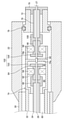
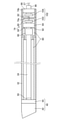
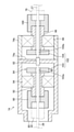
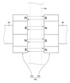
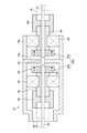
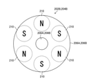
- FIG. 8 It is a block diagram of an endoscope system including a perspective mirror. It is sectional drawing of the tip part of the insertion part. It is sectional drawing of the operation part. It is sectional drawing of an outer cylinder and a case. It is a cross-sectional enlarged view of a case and a tubular part. It is a front view which looked at the 1st magnet and the 2nd magnet from the partition wall side. It is a side view of the 1st magnet and the 2nd magnet. It is sectional drawing of the case and the cylindrical part provided in the operation part of the perspective mirror of 2nd Embodiment. 8 is an enlarged cross-sectional view of the first magnet and the second magnet in FIG.
- FIG. 1 is a block diagram of an endoscope system 12 including a perspective mirror 10. As shown in FIG. 1, the endoscope system 12 includes a perspective mirror 10 of the first embodiment corresponding to the endoscope of the present invention, a processor device 14, a monitor 16, and a light source device 18.
- the perspective mirror 10 is a so-called rigid mirror, and includes an insertion unit 20 and an operation unit 22.
- the insertion portion 20 is formed in a substantially tubular shape (substantially tubular shape) and is inserted into the patient's body.
- the insertion portion 20 has a tip end, a base end, and an insertion shaft Ax.
- a camera unit 24, which will be described later, is provided at the tip of the insertion portion 20.
- a first signal line 26 (signal cable) and a light guide 28 (optical fiber cable) are inserted in the insertion portion 20.
- the first signal line 26 connects the camera unit 24 and the processor device 14 described later together with the second signal line 27 described later.
- the tip of the first signal line 26 is connected to the camera unit 24, and the base end of the first signal line 26 is connected to the second signal line 27 in the operation unit 22. Therefore, the first signal line 26 and the second signal line 27 correspond to the signal lines of the present invention.
- the light guide 28 is provided with a tip end portion (light emitting end face) on the tip end surface of the insertion portion 20, and a base end portion (light incident end face) thereof is connected to the light source device 18.
- the operation unit 22 receives a rotation operation for rotating the viewing direction of the perspective mirror 10 (observation direction, see the optical axis OA in FIG. 2) in the axial direction of the insertion axis Ax (circumferential direction of the insertion unit 20 and the operation unit 22). .. Further, although the operation unit 22 will be described in detail later, the operation unit 22 has an airtight space and a non-airtight space inside thereof, and the base end portion of the first signal line 26 and the second signal line at the boundary between the two spaces. It is connected to the tip of 27 (see FIG. 3). The base end of the second signal line 27 is connected to the processor device 14. As a result, the camera unit 24 and the processor device 14 are electrically connected to each other via the first signal line 26 and the second signal line 27.
- the processor device 14 generates an observation image (moving image) inside the patient's body based on an image pickup signal input from the camera unit 24 via the first signal line 26 and the second signal line 27, and monitors this observation image. Display on 16.
- the light source device 18 supplies illumination light to the light guide 28.
- the illumination light is emitted from the light emitting end surface of the tip portion of the light guide 28 provided on the tip surface of the insertion portion 20.
- FIG. 2 is an enlarged cross-sectional view of the tip of the insertion portion 20.
- the insertion portion 20 includes a substantially tubular outer tube 30 (also referred to as a mantle tube) parallel to the insertion axis Ax, an outer tube 32, and an inner tube 34.
- the outer tube 30 constitutes the outer peripheral wall of the insertion portion 20.
- the opening at the tip of the outer tube 30 is inclined from a posture perpendicular to the insertion shaft Ax.
- the base end portion of the exterior pipe 30 is connected to the operation unit 22 (see FIG. 3), which will be described in detail later.
- the outer cylinder 32 is inserted and arranged inside the outer pipe 30.
- a tip optical system 40 of a camera unit 24, which will be described later, is provided at the tip of the outer cylinder 32.
- the base end portion of the outer cylinder 32 is connected to the case 74 (see FIG. 3) in the operation unit 22, which will be described in detail later.
- an insertion passage 31 for the light guide 28 is formed between the inner peripheral surface of the outer tube 30 and the outer peripheral surface of the outer cylinder 32.
- the inner cylinder 34 corresponds to the shaft member of the present invention, and is inserted and arranged inside the outer cylinder 32.
- a first signal line 26 is inserted inside the inner cylinder 34.
- a base end optical system 50 and an image pickup unit 60 constituting the camera unit 24 described later are provided at the tip of the inner cylinder 34. Further, the base end portion of the inner cylinder 34 is connected to the first connecting member 90 (see FIG. 3) in the operating portion 22, which will be described in detail later.
- the camera unit 24 includes an advanced optical system 40, a proximal optical system 50, and an imaging unit 60.
- the reference numeral OA in the figure is the optical axis of the optical system of the camera unit 24.
- the tip optical system 40 is provided at the tip of the outer cylinder 32.
- the advanced optical system 40 is a perspective optical system that refracts light incident from a direction inclined with respect to the insertion axis Ax in a direction parallel to the insertion axis Ax and guides the light to the proximal optical system 50.
- the tip optical system 40 includes a tip body 42 and a tip lens barrel 44 provided on the tip body 42.
- the tip body 42 constitutes the tip of the insertion portion 20 (outer cylinder 32), and is a cap (cover) that covers the tip lens barrel 44.
- the tip body 42 is formed in a substantially tubular shape parallel to the insertion shaft Ax. Further, in the opening on the tip side of the tip body 42, a cover glass 46 having an inclined posture according to the tilt angle of the objective lens 48a in the tip lens barrel 44, which will be described later, is provided.
- the tip main body 42 is fixed to the inner peripheral surface of the outer tube 30.
- the outer tube 30, the tip optical system 40, and the outer cylinder 32 are integrally rotated in the axial direction of the insertion shaft Ax (hereinafter, simply abbreviated as the axial direction).
- the tip lens barrel 44 houses the objective lens 48a, the prism 48b, and the lens 48c.
- the objective lens 48a is tilted from a posture perpendicular to the insertion axis Ax and faces the cover glass 46.
- the objective lens 48a emits the light incident through the cover glass 46 toward the prism 48b.
- the prism 48b corresponds to the second refractive optical element of the present invention, and the light incident from the objective lens 48a, that is, the light incident from the direction inclined with respect to the insertion axis Ax is directed in the direction parallel to the insertion axis Ax. After refraction, it emits light toward the lens 48c.
- the lens 48c is in a posture perpendicular to the insertion axis Ax, and emits light incident from the prism 48b toward the lens 56 in the proximal lens barrel 52 of the proximal optical system 50 described later.
- the configuration of the optical system in the tip lens barrel 44 is not particularly limited as long as it can guide the light incident from the direction inclined with respect to the insertion axis Ax into the base lens barrel 52.
- the tip lens barrel 44 is formed with a cylindrical portion 45 extending toward the base end side thereof.
- the tubular portion 45 is fitted so as to be rotatable relative to the tip end portion of the base end lens barrel 52 described later in the axial direction.
- the base end lens barrel 52 is fitted to the tip end lens barrel 44 so as to be relatively rotatable in the axial direction.
- the tubular portion 45 is integrally formed with the tip lens barrel 44, but it may be formed separately from the tip lens barrel 44.
- the base end optical system 50 is provided at the tip end portion of the inner cylinder 34, and guides the light incident from the tip end lens barrel 44 to the image pickup unit 60.
- the proximal optical system 50 includes a proximal lens barrel 52, a holder 54, and a prism 55.
- the base end lens barrel 52 is connected (fixed) to the tip end portion of the inner cylinder 34 via the holder 54.
- the base end portion of the base end lens barrel 52 may be directly connected to the tip end portion of the inner cylinder 34, and the holder 54 may be connected to the base end portion of the base end lens barrel 52 inside the inner cylinder 34.
- the tip end portion of the proximal end lens barrel 52 is fitted so as to be relatively rotatable in the axial direction with respect to the opening on the proximal end side of the tubular portion 45.
- the other can rotate relative to one of the tip lens barrel 44 and the proximal lens barrel 52 in the axial direction.
- the proximal end portion of the distal lens barrel 44 may be fitted into the opening on the distal end side of the proximal lens barrel 52 so as to be relatively rotatable in the axial direction.
- a plurality of lenses 56 having an optical axis OA parallel to the insertion axis Ax are provided in the base end lens barrel 52. Each lens 56 emits light incident from the tip lens barrel 44 toward the prism 55.
- the holder 54 is formed in a substantially tubular shape parallel to the insertion shaft Ax, and is fixed to the tip of the inner cylinder 34. Further, the holder 54 is connected and fixed (outer fitting fixed) to the base end portion of the base end lens barrel 52. As a result, the inner cylinder 34 and the base end lens barrel 52 are connected by the holder 54, so that the inner cylinder 34, the base end lens barrel 52, and the holder 54 rotate integrally in the axial direction.
- a prism 55 is held in the opening on the base end side of the holder 54, and an image pickup unit 60 described later is held via the prism 55. Therefore, the image pickup unit 60 rotates in the axial direction integrally with the inner cylinder 34 and the proximal lens barrel 52 via the holder 54 and the prism 55.
- the prism 55 corresponds to the first refractive optical element of the present invention, and is held in the opening on the proximal end side of the holder 54 as described above.
- the prism 55 refracts the light incident through the base end lens barrel 52 by 90 degrees.
- a mirror may be used instead of the prism 55.
- the image pickup unit 60 captures the light that has passed through the tip end lens barrel 44 and the base end lens barrel 52 and is reflected by the prism 55.
- the image pickup unit 60 includes an image pickup element 64 and a circuit board 66.
- the image pickup element 64 is connected (fixed) to the prism 55 in a state of being mounted on the circuit board 66, and is attached to the holder 54 via the prism 55. Therefore, the holder 54 corresponds to the image sensor mounting portion of the present invention. Then, the image pickup device 64 takes an image of the light refracted by the prism 55 and outputs an image pickup signal.
- a CCD (Charge Coupled Device) type image sensor or a CMOS (Complementary Metal Oxide Semiconductor) type image sensor is used as the image sensor 64.
- the image sensor 64 is attached to the holder 54 via the prism 55, but the image sensor 64 may be directly attached to the opening on the proximal end side of the holder 54.
- the image pickup device 64 is held by the holder 54 in a posture perpendicular to the insertion axis Ax (optical axis OA), and has a light receiving surface orthogonal to the optical axis OA.
- the circuit board 66 controls the drive of the image pickup element 64. Further, the tip of the first signal line 26 is connected to the circuit board 66 via the connector 68. Then, the circuit board 66 outputs the image pickup signal of the image pickup element 64 to the first signal line 26 via the connector 68.
- FIG. 3 is a cross-sectional view of the operation unit 22.
- the operation unit 22 is an operation ring formed in a substantially tubular shape parallel to the insertion axis Ax, and receives a rotation operation in the axial direction by the operator.
- the base end portion of the exterior pipe 30 described above is connected to the tip end portion of the operation unit 22.
- the outer cylinder 32 and the tip optical system 40 are rotated in the same direction via the outer tube 30. ..
- the viewing direction (observation direction) of the perspective mirror 10 can be rotated.
- the base end portions of the outer cylinder 32 and the inner cylinder 34 are inserted into the opening on the tip end side of the operation unit 22. Further, an extension portion 72 is provided in the opening on the base end side of the operation portion 22. Further, a case 74 is provided inside the operation unit 22.
- the extending portion 72 is formed in a substantially tubular shape parallel to the insertion shaft Ax and having a diameter smaller than the inner diameter of the operating portion 22.
- An O-ring 76 is externally fitted on the outer peripheral surface of the tip of the extending portion 72.
- the tip of the extending portion 72 is rotatably held on the inner peripheral surface of the base end portion of the operating portion 22 via the O-ring 76.
- the extending portion 72 is held by the base end portion of the operating portion 22 so as to be relatively rotatable in the axial direction.
- this rotational force is not transmitted to the extension unit 72.
- the extending portion 78 is inserted inside the extending portion 72.
- the extending portion 78 is formed in a substantially tubular shape parallel to the insertion shaft Ax, and a second signal line 27 is inserted therein.
- the base end portion of the extending portion 78 is fixed to the extending portion 72 via a fixing member 79.
- the extending portion 72 and the extending portion 78 are integrated.
- the tip portion of the extending portion 78 is connected to the magnet coupling 102 via the second connecting member 100 and the second bearing receiving member 96, which will be described in detail later.
- the case 74 has a substantially tubular shape parallel to the insertion shaft Ax and has a diameter smaller than the inner diameter of the operation unit 22, and is housed inside the operation unit 22.
- the case 74 is supported in the internal space of the operation unit 22 by the outer cylinder 32, the extending portion 78, and the like.
- the tip end side of the case 74 is connected to the base end portion of the outer cylinder 32.
- the case 74 rotates integrally with the outer cylinder 32 in the axial direction.
- this rotational force is transmitted to the outer tube 30, the tip optical system 40, the outer cylinder 32, and the case 74. These are rotated in the same direction as the operation unit 22.
- a partition wall 74a perpendicular to the insertion shaft Ax is provided inside the case 74, for example, in the opening on the base end side of the case 74.
- the partition wall 74a closes the opening on the base end side of the case 74.
- a cylindrical portion 74b parallel to the insertion shaft Ax is provided on the base end side of the case 74.
- the tubular portion 74b is formed with the same diameter as the case 74 in the present embodiment, but may be formed with a diameter different from that of the case 74. Further, the tubular portion 74b may be integrally formed with the case 74. In this case, the base end portion of the case 74 functions as the tubular portion 74b. Inside the tubular portion 74b, the tip portion of the second signal line 27 is arranged in addition to a part of the connecting portion 84 described later.
- FIG. 4 is a cross-sectional view of the outer cylinder 32 and the case 74.
- a closed space 80 airtight space
- the inner cylinder 34, the image pickup unit 60, and the first signal line 26 are formed in the closed space 80. Etc. are placed.
- the tip side of the enclosed space 80 is defined by the tip optical system 40.
- the base end side of the closed space 80 is defined by the partition wall 74a.
- FIG. 5 is an enlarged cross-sectional view of the case 74 and the tubular portion 74b. As shown in FIGS. 3 to 5, the partition wall 74a, the airtight connector 82, and the connecting portion 84 described above are provided inside the case 74 and the tubular portion 74b.
- the airtight connector 82 is provided so as to be rotatable relative to the partition wall 74a in the axial direction so as to penetrate the inside and outside of the sealed space 80.
- the airtight connector 82 electrically connects the first signal line 26 inside the case 74 (inside the closed space 80) and the second signal line 27 inside the tubular portion 74b (outside the closed space 80).
- the airtight connector 82 may be fixed to the partition wall 74a.
- the connecting portion 84 is provided inside the case 74 and the tubular portion 74b so as to be relatively rotatable in the axial direction with respect to the case 74 and the tubular portion 74b.
- the first signal line 26 and the second signal line 27 are inserted inside the connecting portion 84.
- the connecting portion 84 magnetically connects the base end portion of the inner cylinder 34 inside the case 74 (inside the closed space 80) and the tip end portion of the extending portion 78 outside the closed space 80 with the partition wall 74a sandwiched between them. Connect (connect).
- the connecting portion 84 includes a first connecting member 90, a first bearing receiving member 92, a first bearing 94, a second bearing receiving member 96, a second bearing 98, a second connecting member 100, and a magnet coupling. 102 and.
- the first connecting member 90 and the first bearing receiving member 92 are provided in the case 74 (inside the closed space 80), and are formed in a substantially tubular shape parallel to the insertion shaft Ax. Then, the first signal line 26 is inserted inside the first connecting member 90 and the first bearing receiving member 92.
- the first connecting member 90 connects the base end portion of the inner cylinder 34 and the first bearing receiving member 92 in the case 74 (in the closed space 80). As a result, the first bearing receiving member 92 is connected to the base end side of the inner cylinder 34 via the first connecting member 90.
- the tip end side of the first bearing receiving member 92 is connected to the first connecting member 90 as described above, and the proximal end side thereof is fixed to the first magnet 103 of the magnet coupling 102 described later. Further, a first bearing 94 inscribed in the case 74 is fixed to the outer peripheral surface of the first bearing receiving member 92. As a result, the first bearing receiving member 92 and the first magnet 103 are held in the case 74 so as to be relatively rotatable in the axial direction with respect to the case 74. As the first bearing 94, various known radial bearings such as ball bearings and roller bearings are used.
- the second bearing receiving member 96 is provided inside the tubular portion 74b (outside the closed space 80), and the second connecting member 100 is provided between the second bearing receiving member 96 and the extending portion 78.
- the second bearing receiving member 96 and the second connecting member 100 are formed in a substantially tubular shape parallel to the insertion shaft Ax, and the second signal line 27 is inserted therein.
- the tip of the second bearing receiving member 96 is fixed to the second magnet 104 of the magnet coupling 102 described later in the tubular portion 74b, and the base end thereof is connected to the second connecting member 100. Further, a second bearing 98 inscribed in the tubular portion 74b is fixed to the outer peripheral surface of the second bearing receiving member 96. As a result, the second bearing receiving member 96 and the second magnet 104 are held in the tubular portion 74b so as to be relatively rotatable in the axial direction with respect to the tubular portion 74b. As the second bearing 98, various known radial bearings are used as in the case of the first bearing 94.
- the second connecting member 100 connects the second bearing receiving member 96 and the tip end portion of the extending portion 78. As a result, the second bearing receiving member 96 is connected to the tip end side of the extending portion 78 via the second connecting member 100.
- the magnet coupling 102 includes a first magnet 103 provided in the case 74 (inside the closed space 80) and a second magnet 104 provided in the tubular portion 74b (outside the closed space 80) with the partition wall 74a sandwiched between them. And, it is composed of.
- the magnet coupling 102 is a magnetic connecting member that magnetically connects the first bearing receiving member 92 (inner cylinder 34) and the second bearing receiving member 96 (extending portion 78).
- FIG. 6 is a front view of the first magnet 103 and the second magnet 104 as viewed from the partition wall 74a side.
- FIG. 7 is a side view of the first magnet 103 and the second magnet 104.
- the first magnet 103 and the second magnet 104 have a disk shape (ring shape) parallel to the partition wall 74a (perpendicular to the insertion axis Ax).
- An insertion hole 103a through which the first signal line 26 is inserted is formed in the central portion of the first magnet 103
- an insertion hole 104a through which the second signal line 27 is inserted is formed in the central portion of the second magnet 104.
- the first magnet 103 and the second magnet 104 of the present embodiment are of the so-called single-sided multi-pole type, and a plurality of sets of N poles and S poles are arranged along the axial direction on the surface side facing the partition wall 74a. It is formed at angular intervals.
- the first magnet 103 and the second magnet 104 are not limited to the single-sided multi-pole type, but may be a double-sided multi-pole type, and the number of poles is not particularly limited as long as it has two or more poles. Further, the shapes of the first magnet 103 and the second magnet 104 are not limited to the disk shape, and may be any shape such as a polygonal shape parallel to the partition wall 74a.
- the first magnet 103 and the second magnet 104 As shown in FIG. 7, in the first magnet 103 and the second magnet 104, one of the individual N poles faces the other individual S pole and one individual S pole faces the other individual N pole.
- the partition wall 74a is arranged so as to face the pole.
- the first magnet 103 and the second magnet 104 are magnetically connected in the thrust direction of the insertion shaft Ax [direction parallel to the insertion shaft Ax (axial direction)] with the partition wall 74a sandwiched between them.
- the inner cylinder 34 and the extending portion 72 are magnetically connected via the magnet coupling 102.
- the magnet coupling 102 of the first embodiment can be configured by two first magnets 103 and a second magnet 104, and the number of magnets is larger than that of the conventional example in which a large number of magnets need to be arranged concentrically. Can be reduced. As a result, it is possible to prevent the assembly work of the operation unit 22 from becoming complicated and reduce the cost.
- the transmission torque can be increased by reducing the number of poles of each of the first magnet 103 and the second magnet 104, but it is permissible from one of the first magnet 103 and the second magnet 104 to the other.
- the amount of slip between the first magnet 103 and the second magnet 104 that occurs when a transmission torque greater than or equal to the torque is transmitted becomes large.
- the slip amount described above can be reduced, but the transmission torque is lowered.
- a magnet coupling 200 (see FIG. 8) different from the magnet coupling 102 of the first embodiment is used. Be prepared.
- FIG. 8 is an enlarged cross-sectional view of the case 74 and the tubular portion 74b provided in the operation portion 22 of the perspective mirror 10 (corresponding to the endoscope of the present invention) of the second embodiment.
- the perspective mirror 10 of the second embodiment has basically the same configuration as the perspective mirror 10 of the first embodiment, except that the magnet coupling 200 is provided instead of the magnet coupling 102. Therefore, those having the same function or configuration as those of the first embodiment are designated by the same reference numerals and the description thereof will be omitted.
- the magnet coupling 200 includes a first magnet 202 provided in the case 74 (inside the closed space 80) with a partition wall 74a in between, and a second magnet provided in the tubular portion 74b (outside the closed space 80). It is composed of 204 and.
- the magnet coupling 200 magnetically connects the first bearing receiving member 92 (inner cylinder 34) and the second bearing receiving member 96 (extending portion 78) as in the first embodiment.
- FIG. 9 is an enlarged cross-sectional view of the first magnet 202 and the second magnet 204 in FIG. 8, and an enlarged front view of the first magnet 202 and the second magnet 204 as viewed from the partition wall 74a side, respectively.
- the first magnet 202 includes a magnet holding portion 206A and eight individual magnets 210.
- the second magnet 204 has basically the same configuration as the first magnet 202, and includes a magnet holding portion 206B and eight individual magnets 210.
- the magnet holding portions 206A and 206B are formed in an annular shape when viewed from the axial side of the insertion shaft Ax, that is, when viewed from the partition wall 74a side.
- As the material of these magnet holding portions 206A and 206B for example, a non-magnetic material is used.
- the magnet holding portion 206A is fixed to the base end side of the first bearing receiving member 92 (inner cylinder 34), and has an insertion hole 208A in which the first signal line 26 is inserted in the central portion.
- the magnet holding portion 206B is fixed to the tip end side of the second bearing receiving member 96, and has an insertion hole 208B in the central portion through which the second signal line 27 is inserted.
- a fitting hole (not shown) into which eight individual magnets 210 are fitted is provided. It is formed at equal intervals along the axial direction around the insertion axis Ax.
- the individual magnet 210 is a needle-shaped magnet or a rod-shaped magnet extending in a direction parallel to the insertion axis Ax.
- the individual magnet 210 is formed in a columnar shape (including a substantially columnar shape), and the length (total length) along the axial direction of the insertion shaft Ax is formed longer than the diameter thereof. ing.
- the individual magnet 210 has a magnetic pole in the axial direction of the insertion shaft Ax, that is, is divided into an N pole and an S pole in the axial direction of the insertion shaft Ax, and has both end faces in the axial direction of the insertion shaft Ax. The magnetic force is the largest.
- the magnet holding portions 206A and 206B are provided with eight individual magnets 210 at equal intervals along the axial direction thereof. At this time, each individual magnet 210 is inverted so that the other magnetic pole is inverted with respect to one magnetic pole of the individual magnets 210 adjacent to each other in the axial direction, that is, the magnetic poles of the individual magnets 210 are alternately inverted in the axial direction. Magnets 210 are provided in the magnet holding portions 206A and 206B, respectively. The end surface of each individual magnet 210 on the partition wall 74a side is exposed on the partition wall facing surfaces of the magnet holding portions 206A and 206B.
- the end faces of the N poles of the four individual magnets 210 of the magnet holding portion 206A and the end faces of the S poles of the four individual magnets 210 of the magnet holding portion 206B are arranged to face each other with the partition wall 74a in between.
- the end faces of the S poles of the four individual magnets 210 of the magnet holding portion 206A and the end faces of the N poles of the four individual magnets 210 of the magnet holding portion 206B are arranged to face each other with the partition wall 74a in between. Magnet.
- the first magnet 202 and the second magnet 204 are magnetically connected with the partition wall 74a sandwiched between them, so that they extend to the inner cylinder 34 via the magnet coupling 200.
- the portion 72 is magnetically connected.
- a plurality of individual magnets 210 are provided at intervals along the axial direction of the magnet holding portions 206A and 206B on the partition wall facing surface.
- the weakening of the magnetic force between the exposed north and south poles is reduced as compared with the first embodiment.
- the end surface having the strongest magnetic force among the individual magnets 210 can be exposed on the partition wall facing surfaces of the magnet holding portions 206A and 206B.
- the north pole and the south pole are formed in one magnet (first magnet 103 and second magnet 104) along the axial direction. It is possible to improve the transmission torque as compared with the case where and are alternately formed.
- the individual magnets 210 are provided eccentrically on the outer peripheral side of the magnet holding portions 206A and 206B rather than on the inner peripheral side when the magnet holding portions 206A and 206B are viewed from the partition wall 74a side. Thereby, the transmission torque transmitted from one of the first magnet 202 and the second magnet 204 to the other can be further improved.
- the transmission torque is improved, so that when the operator rotates the operation unit 22, the inner cylinder 34 (base end optical system 50 and the image pickup unit) together with the outer cylinder 32. 60) is reliably prevented from rotating in the axial direction.
- the inner cylinder 34 base end optical system 50 and the imaging portion 60
- the transmission torque is improved, so that when the operator rotates the extension portion 72, the inner cylinder 34 (base end optical system 50 and the imaging portion 60) can be rotated in the axial direction without delay.
- the transmission torque can be improved without reducing the number of poles as in the magnet coupling 102 of the first embodiment, so that the first magnet 202 and the second magnet 204 can be improved. It is also possible to reduce the slip amount when a transmission torque equal to or greater than the allowable torque is transmitted from one to the other. As a result, the perspective mirror 10 of the second embodiment can achieve both improvement of transmission torque and reduction of slip amount by the magnet coupling 200.
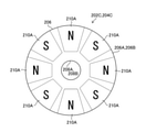
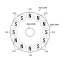
- FIG. 10 is a front view of the first magnet 202A and the second magnet 204A, which are the first modification of the second embodiment, as viewed from the partition wall 74a side, respectively.
- FIG. 11 is a front view of the first magnet 202B and the second magnet 204B, which are the second modification of the second embodiment, as viewed from the partition wall 74a side, respectively.
- the first magnet 202 and the second magnet 204 each include eight individual magnets 210, but the number of individual magnets 210 is not particularly limited.
- the number of individual magnets 210 provided in the first magnet 202A and the second magnet 204A, respectively may be increased from eight, or as shown in FIG. 11, the first magnet 202B and the second magnet 204B may be increased.
- the number of individual magnets 210 provided in each of the magnets may be reduced from eight.
- FIG. 12 is a front view of the first magnet 202C and the second magnet 204C, which are the third modification of the second embodiment, as viewed from the partition wall 74a side, respectively.
- FIG. 13 is a front view of the first magnet 202D and the second magnet 204D, which are the fourth modification of the second embodiment, as viewed from the partition wall 74a side, respectively.
- the first magnet 202 and the second magnet 204 each include a plurality of columnar individual magnets 210, but the shape of the individual magnets 210 is not particularly limited.
- a plurality of individual magnets 210A having substantially trapezoidal columns are provided for the first magnet 202C and the second magnet 204C, or for the first magnet 202D and the second magnet 204D as shown in FIG.
- a plurality of individual magnets 210B having a substantially square columnar shape may be provided.
- FIG. 14 is a front view of the first magnet 202E and the second magnet 204E, which are the fifth modification of the second embodiment, as viewed from the partition wall 74a side, respectively.
- the magnetic poles of the individual magnets 210 provided in the magnet holding portions 206A and 206B are alternately inverted in the axial direction, but the present invention is not limited to this.
- the magnetic poles of some of the individual magnets 210 adjacent to each other in the axial direction on the partition facing surface may be the same.
- a plurality of (three in this case) individual magnets 210 are regarded as one magnet group, and each individual magnet 210 is a magnet holding portion so that the magnetic poles of the magnet group are alternately inverted in the axial direction. It is provided in 206A and 206B, respectively.
- each individual magnet 210 is eccentrically provided on the outer peripheral side of the magnet holding portions 206A and 206B, but is eccentrically provided on the inner peripheral side of the magnet holding portions 206A and 206B, or the magnet is held. It may be provided at the center position between the inner circumference and the outer circumference of the portions 206A and 206B.
- the magnet holding portions 206A and 206B are formed in an annular shape, and a plurality of individual magnets 210 are provided at equal intervals along the axial direction of the magnet holding portions 206A and 206B.
- the shapes of the holding portions 206A and 206B and the arrangement pattern of the individual magnets 210 are not particularly limited and can be changed as appropriate.
- the hollow inner cylinder 34 has been described as an example of the shaft member of the present invention, but a solid shaft member may be inserted into the outer cylinder 32.
- the inner cylinder 34 and the first bearing receiving member 92 are connected via the first connecting member 90, and the extending portion 78 and the second bearing receiving member 96 are connected via the second connecting member 100.
- the first bearing receiving member 92 may be directly connected to the inner cylinder 34, and the second bearing receiving member 96 may be directly connected to the extending portion 78.
- the extension portion 72 is provided at the base end portion of the operation portion 22 so as to be relatively rotatable, and the extension portion 78 is inserted inside the extension portion 72.
- the existing portion 78 may be integrally molded.
- the case 74 is provided with the tubular portion 74b, but the tubular portion 74b may be omitted.
- the second bearing receiving member 96 and the second bearing 98 are omitted, and the tip portion of the extending portion 78 is connected to the second magnet 104.
- the perspective mirror 10 has been described by taking a rigid mirror as an example, but the present invention can also be applied to a flexible mirror. Further, in the above embodiment, the perspective mirror 10 has been described as an example of the endoscope of the present invention, but the outer cylinder can be rotated relative to the inner cylinder in the axial direction according to the rotation operation of the operation unit. The present invention can be applied to various endoscopes.
Landscapes
- Health & Medical Sciences (AREA)
- Life Sciences & Earth Sciences (AREA)
- Surgery (AREA)
- Physics & Mathematics (AREA)
- Optics & Photonics (AREA)
- Engineering & Computer Science (AREA)
- Biomedical Technology (AREA)
- General Health & Medical Sciences (AREA)
- Pathology (AREA)
- Nuclear Medicine, Radiotherapy & Molecular Imaging (AREA)
- Biophysics (AREA)
- Heart & Thoracic Surgery (AREA)
- Medical Informatics (AREA)
- Molecular Biology (AREA)
- Animal Behavior & Ethology (AREA)
- Radiology & Medical Imaging (AREA)
- Public Health (AREA)
- Veterinary Medicine (AREA)
- Astronomy & Astrophysics (AREA)
- General Physics & Mathematics (AREA)
- Multimedia (AREA)
- Endoscopes (AREA)
- Instruments For Viewing The Inside Of Hollow Bodies (AREA)
Priority Applications (4)
| Application Number | Priority Date | Filing Date | Title |
|---|---|---|---|
| DE112021003434.0T DE112021003434T5 (de) | 2020-08-28 | 2021-08-23 | Endoskop |
| JP2022544589A JP7507867B2 (ja) | 2020-08-28 | 2021-08-23 | 内視鏡 |
| CN202180056794.1A CN116075764B (zh) | 2020-08-28 | 2021-08-23 | 内窥镜 |
| US18/162,476 US20230172434A1 (en) | 2020-08-28 | 2023-01-31 | Endoscope |
Applications Claiming Priority (4)
| Application Number | Priority Date | Filing Date | Title |
|---|---|---|---|
| JP2020-144324 | 2020-08-28 | ||
| JP2020144324 | 2020-08-28 | ||
| JP2021097243 | 2021-06-10 | ||
| JP2021-097243 | 2021-06-10 |
Related Child Applications (1)
| Application Number | Title | Priority Date | Filing Date |
|---|---|---|---|
| US18/162,476 Continuation US20230172434A1 (en) | 2020-08-28 | 2023-01-31 | Endoscope |
Publications (1)
| Publication Number | Publication Date |
|---|---|
| WO2022045071A1 true WO2022045071A1 (ja) | 2022-03-03 |
Family
ID=80353348
Family Applications (1)
| Application Number | Title | Priority Date | Filing Date |
|---|---|---|---|
| PCT/JP2021/030827 Ceased WO2022045071A1 (ja) | 2020-08-28 | 2021-08-23 | 内視鏡 |
Country Status (5)
| Country | Link |
|---|---|
| US (1) | US20230172434A1 (cg-RX-API-DMAC7.html) |
| JP (1) | JP7507867B2 (cg-RX-API-DMAC7.html) |
| CN (1) | CN116075764B (cg-RX-API-DMAC7.html) |
| DE (1) | DE112021003434T5 (cg-RX-API-DMAC7.html) |
| WO (1) | WO2022045071A1 (cg-RX-API-DMAC7.html) |
Families Citing this family (1)
| Publication number | Priority date | Publication date | Assignee | Title |
|---|---|---|---|---|
| JP2024123971A (ja) * | 2023-03-02 | 2024-09-12 | 富士フイルム株式会社 | 内視鏡 |
Citations (7)
| Publication number | Priority date | Publication date | Assignee | Title |
|---|---|---|---|---|
| JP2002189162A (ja) * | 2000-12-21 | 2002-07-05 | Asahi Optical Co Ltd | レンズ駆動装置 |
| JP2006025913A (ja) * | 2004-07-13 | 2006-02-02 | Olympus Corp | 医療機器 |
| JP2007037783A (ja) * | 2005-08-03 | 2007-02-15 | Olympus Medical Systems Corp | 内視鏡用撮像装置と内視鏡用連結装置 |
| JP2008188081A (ja) * | 2007-02-01 | 2008-08-21 | Hoya Corp | Octプローブおよびoctシステム。 |
| US20110275890A1 (en) * | 2009-01-09 | 2011-11-10 | Washington University In St. Louis | Miniaturized photoacoustic imaging apparatus including a rotatable reflector |
| CN103767660A (zh) * | 2014-02-20 | 2014-05-07 | 上海交通大学 | 一种内窥镜 |
| WO2015022760A1 (ja) * | 2013-08-10 | 2015-02-19 | 並木精密宝石株式会社 | 光イメージング用プローブ |
Family Cites Families (8)
| Publication number | Priority date | Publication date | Assignee | Title |
|---|---|---|---|---|
| JPS58203746A (ja) * | 1982-05-25 | 1983-11-28 | オリンパス光学工業株式会社 | 体腔内超音波走査装置 |
| US5836867A (en) * | 1996-11-27 | 1998-11-17 | Linvatec Corporation | Magnetic coupling assembly for endoscope |
| CN101622773B (zh) | 2007-02-26 | 2012-05-23 | 奥林巴斯医疗株式会社 | 磁驱动器、磁驱动器的工作方法及采用该磁驱动器的胶囊型内窥镜 |
| JP2009160243A (ja) * | 2008-01-08 | 2009-07-23 | Fujifilm Corp | 内視鏡操作装置及び内視鏡 |
| DE102011090132B4 (de) * | 2011-12-29 | 2017-09-14 | Olympus Winter & Ibe Gmbh | Videoendoskop und Videoendoskopsystem |
| EP2835091A4 (en) * | 2012-03-21 | 2015-12-09 | Olympus Corp | ENDOSCOPE AND HELICAL ROTATION ELEMENT INSTALLED ON THE INTRODUCTION SECTION OF SAID ENDOSCOPE |
| CN106102552A (zh) * | 2014-03-28 | 2016-11-09 | 富士胶片株式会社 | 内窥镜用摄像装置 |
| DE102017124981B4 (de) * | 2017-10-25 | 2024-03-07 | Schölly Fiberoptic GmbH | Magnetische Kupplung |
-
2021
- 2021-08-23 DE DE112021003434.0T patent/DE112021003434T5/de active Pending
- 2021-08-23 CN CN202180056794.1A patent/CN116075764B/zh active Active
- 2021-08-23 WO PCT/JP2021/030827 patent/WO2022045071A1/ja not_active Ceased
- 2021-08-23 JP JP2022544589A patent/JP7507867B2/ja active Active
-
2023
- 2023-01-31 US US18/162,476 patent/US20230172434A1/en active Pending
Patent Citations (7)
| Publication number | Priority date | Publication date | Assignee | Title |
|---|---|---|---|---|
| JP2002189162A (ja) * | 2000-12-21 | 2002-07-05 | Asahi Optical Co Ltd | レンズ駆動装置 |
| JP2006025913A (ja) * | 2004-07-13 | 2006-02-02 | Olympus Corp | 医療機器 |
| JP2007037783A (ja) * | 2005-08-03 | 2007-02-15 | Olympus Medical Systems Corp | 内視鏡用撮像装置と内視鏡用連結装置 |
| JP2008188081A (ja) * | 2007-02-01 | 2008-08-21 | Hoya Corp | Octプローブおよびoctシステム。 |
| US20110275890A1 (en) * | 2009-01-09 | 2011-11-10 | Washington University In St. Louis | Miniaturized photoacoustic imaging apparatus including a rotatable reflector |
| WO2015022760A1 (ja) * | 2013-08-10 | 2015-02-19 | 並木精密宝石株式会社 | 光イメージング用プローブ |
| CN103767660A (zh) * | 2014-02-20 | 2014-05-07 | 上海交通大学 | 一种内窥镜 |
Also Published As
| Publication number | Publication date |
|---|---|
| CN116075764A (zh) | 2023-05-05 |
| DE112021003434T5 (de) | 2023-05-11 |
| CN116075764B (zh) | 2026-02-03 |
| US20230172434A1 (en) | 2023-06-08 |
| JPWO2022045071A1 (cg-RX-API-DMAC7.html) | 2022-03-03 |
| JP7507867B2 (ja) | 2024-06-28 |
Similar Documents
| Publication | Publication Date | Title |
|---|---|---|
| US10203493B2 (en) | Optical systems for multi-sensor endoscopes | |
| JP5695180B2 (ja) | 内視鏡カメラおよび内視鏡装置 | |
| JP3526531B2 (ja) | 立体内視鏡の先端構造 | |
| RU2770743C1 (ru) | Электронный эндоскоп и система электронного эндоскопа | |
| JP2009251574A (ja) | 広視野内視鏡 | |
| JP7507867B2 (ja) | 内視鏡 | |
| JP2001174713A (ja) | 対物光学系および内視鏡の対物光学系 | |
| JP5150388B2 (ja) | 内視鏡 | |
| JP3001035B2 (ja) | 内視鏡用光学アダプタ | |
| US20250110325A1 (en) | Optical systems for multi-sensor endoscopes | |
| JP2929473B2 (ja) | 工業用内視鏡装置 | |
| US12316944B2 (en) | Image pickup device and endoscope | |
| WO2017086298A1 (ja) | 側視光学アダプタ | |
| US20230094202A1 (en) | Endoscope | |
| JP2007037783A (ja) | 内視鏡用撮像装置と内視鏡用連結装置 | |
| JP2023051679A (ja) | 内視鏡 | |
| JP7768742B2 (ja) | 内視鏡 | |
| US20230165435A1 (en) | Operation unit and endoscope | |
| JP2022039345A (ja) | 内視鏡 | |
| CN115886697B (zh) | 内窥镜及内窥镜系统 | |
| JP2022039346A (ja) | 内視鏡及び撮影装置 | |
| JPH02100013A (ja) | 内視鏡用光学アダプタ | |
| JPH06118315A (ja) | 内視鏡のフォーカス固定装置 | |
| JPS63304220A (ja) | 硬性電子内視鏡装置 |
Legal Events
| Date | Code | Title | Description |
|---|---|---|---|
| 121 | Ep: the epo has been informed by wipo that ep was designated in this application |
Ref document number: 21861496 Country of ref document: EP Kind code of ref document: A1 |
|
| ENP | Entry into the national phase |
Ref document number: 2022544589 Country of ref document: JP Kind code of ref document: A |
|
| 122 | Ep: pct application non-entry in european phase |
Ref document number: 21861496 Country of ref document: EP Kind code of ref document: A1 |