WO2022039243A1 - 塗布具 - Google Patents
塗布具 Download PDFInfo
- Publication number
- WO2022039243A1 WO2022039243A1 PCT/JP2021/030471 JP2021030471W WO2022039243A1 WO 2022039243 A1 WO2022039243 A1 WO 2022039243A1 JP 2021030471 W JP2021030471 W JP 2021030471W WO 2022039243 A1 WO2022039243 A1 WO 2022039243A1
- Authority
- WO
- WIPO (PCT)
- Prior art keywords
- shaft
- protrusion
- cap
- front shaft
- coating
- Prior art date
- Legal status (The legal status is an assumption and is not a legal conclusion. Google has not performed a legal analysis and makes no representation as to the accuracy of the status listed.)
- Ceased
Links
Images


Classifications
-
- B—PERFORMING OPERATIONS; TRANSPORTING
- B43—WRITING OR DRAWING IMPLEMENTS; BUREAU ACCESSORIES
- B43K—IMPLEMENTS FOR WRITING OR DRAWING
- B43K23/00—Holders or connectors for writing implements; Means for protecting the writing-points
- B43K23/08—Protecting means, e.g. caps
- B43K23/12—Protecting means, e.g. caps for pens
-
- A—HUMAN NECESSITIES
- A45—HAND OR TRAVELLING ARTICLES
- A45D—HAIRDRESSING OR SHAVING EQUIPMENT; EQUIPMENT FOR COSMETICS OR COSMETIC TREATMENTS, e.g. FOR MANICURING OR PEDICURING
- A45D34/00—Containers or accessories specially adapted for handling liquid toiletry or cosmetic substances, e.g. perfumes
- A45D34/04—Appliances specially adapted for applying liquid, e.g. using roller or ball
- A45D34/042—Appliances specially adapted for applying liquid, e.g. using roller or ball using a brush or the like
-
- A—HUMAN NECESSITIES
- A45—HAND OR TRAVELLING ARTICLES
- A45D—HAIRDRESSING OR SHAVING EQUIPMENT; EQUIPMENT FOR COSMETICS OR COSMETIC TREATMENTS, e.g. FOR MANICURING OR PEDICURING
- A45D40/00—Casings or accessories specially adapted for storing or handling solid or pasty toiletry or cosmetic substances, e.g. shaving soaps or lipsticks
- A45D40/20—Pencil-like cosmetics; Simple holders for handling stick-shaped cosmetics or shaving soap while in use
-
- A—HUMAN NECESSITIES
- A45—HAND OR TRAVELLING ARTICLES
- A45D—HAIRDRESSING OR SHAVING EQUIPMENT; EQUIPMENT FOR COSMETICS OR COSMETIC TREATMENTS, e.g. FOR MANICURING OR PEDICURING
- A45D40/00—Casings or accessories specially adapted for storing or handling solid or pasty toiletry or cosmetic substances, e.g. shaving soaps or lipsticks
- A45D40/26—Appliances specially adapted for applying pasty paint, e.g. using roller, using a ball
-
- B—PERFORMING OPERATIONS; TRANSPORTING
- B43—WRITING OR DRAWING IMPLEMENTS; BUREAU ACCESSORIES
- B43K—IMPLEMENTS FOR WRITING OR DRAWING
- B43K8/00—Pens with writing-points other than nibs or balls
- B43K8/02—Pens with writing-points other than nibs or balls with writing-points comprising fibres, felt, or similar porous or capillary material
- B43K8/04—Arrangements for feeding ink to writing-points
- B43K8/06—Wick feed from within reservoir to writing-points
- B43K8/08—Wick separate from writing-points
-
- B—PERFORMING OPERATIONS; TRANSPORTING
- B43—WRITING OR DRAWING IMPLEMENTS; BUREAU ACCESSORIES
- B43K—IMPLEMENTS FOR WRITING OR DRAWING
- B43K5/00—Pens with ink reservoirs in holders, e.g. fountain-pens
- B43K5/18—Arrangements for feeding the ink to the nibs
-
- B—PERFORMING OPERATIONS; TRANSPORTING
- B43—WRITING OR DRAWING IMPLEMENTS; BUREAU ACCESSORIES
- B43K—IMPLEMENTS FOR WRITING OR DRAWING
- B43K8/00—Pens with writing-points other than nibs or balls
- B43K8/02—Pens with writing-points other than nibs or balls with writing-points comprising fibres, felt, or similar porous or capillary material
- B43K8/04—Arrangements for feeding ink to writing-points
- B43K8/06—Wick feed from within reservoir to writing-points
Definitions
- This disclosure relates to an applicator for applying a coating liquid such as cosmetics.
- a collector which is a comb-shaped guide member that temporarily stores the coating liquid to be supplied to the coating body, is provided in the front shaft in which the coating body is projected from the tip, and the coating liquid tank is inserted into the front shaft from the rear.
- a coating tool that makes it possible to distribute the coating liquid in the coating liquid tank to the collector and the coating body.
- the outer shaft covering the coating liquid tank is fitted to the front shaft from the rear part of the front shaft, and the protrusion of the outer shaft fitting is bulged in the outer diameter direction on the outer peripheral surface of the rear part of the front shaft.
- the coating tool of Patent Document 1 has a structure in which the outer shaft is fitted to the outer peripheral surface of the front shaft when the coating liquid tank is replaced, but the protrusion of the front shaft is locked to the inner peripheral surface of the outer shaft. Therefore, there was a problem that it was difficult to judge the replacement completion status.
- This disclosure is intended to provide a liquid cosmetic coating tool that can easily determine the replacement completion state of the coating liquid tank in view of such circumstances.
- An embodiment of the present disclosure comprises a front shaft for mounting a coating liquid tank for containing a liquid cosmetic to be supplied to the coating body, and a rear shaft mounted on the front shaft to cover the coating liquid tank, and the outer periphery of the front shaft is provided. It has a male threaded portion and a first engaging portion located behind the male threaded portion and formed along the circumferential direction, and is screwed to the male threaded portion on the inner circumference of the rear shaft. It is a liquid cosmetic application tool having a female screw portion for fitting and a second engaging portion for engaging with the first engaging portion.
- a cap that can be attached to a front shaft is provided to cover the coating body, a first protrusion is formed on the inner surface of the cap, and a second protrusion is formed on the outer peripheral surface of the front shaft.
- the first protrusion and the second protrusion on the outer peripheral surface can mesh with each other, and the second protrusion is on the end surface of the flange on the outer periphery of the front shaft. It is preferably formed.
- the inner front shaft is provided on the inner circumference of the front shaft and a triangular top is formed on the inner peripheral surface of the inner front shaft.
- a male screw portion and a first engaging portion located behind the male screw portion and formed along the circumferential direction are provided on the outer periphery of the front shaft.
- the inner circumference of the rear shaft has a female screw portion for screwing into the male screw portion and a second engaging portion for engaging with the first engaging portion.
- FIG. 1 is a component diagram of the front axis of the applicator, where (a) is a perspective view from the rear, (b) is a perspective view from the front, (c) is a perspective view from the rear, and (d) is a front view.
- the figure, (e) is a perspective view from the other side, and (f) is a vertical sectional view taken along the line FF of (d).
- the parts of the cap in the applicator of FIG. 1, (a) is a perspective view from the rear, (b) is a perspective view from the front, (c) is a perspective view from the rear, and (d) is a front view.
- FIG. 3 is a vertical cross-sectional component diagram of the rear axle of the coating tool of FIG. 1 is a component diagram of the inner tip of the applicator, where (a) is a perspective view from the rear, (b) is a perspective view from the front, (c) is a perspective view from the rear, and (d) is. It is a front view. It is explanatory drawing of the coating tool which concerns on 2nd Embodiment of this disclosure, (a) is the whole front view, (b) is the vertical sectional view along line BB of (a), (c) is the front part.
- FIG. 7 is a component diagram of the front axis of the applicator, where (a) is a perspective view from the rear, (b) is a perspective view from the front, (c) is a perspective view from the rear, and (d) is a front view.
- the figure, (e) is a perspective view from the other side, and (f) is a vertical sectional view taken along the line FF of (d).
- 7 is a component diagram of the cap in the applicator, where (a) is a perspective view from the rear, (b) is a perspective view from the front, (c) is a perspective view from the rear, and (d) is a front view.
- (E) is a perspective view from the other side, (f) is a detailed view of the F portion of (a), and (g) is a vertical sectional view along the GG line of (d).
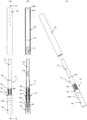
- FIG. 1 is an overall explanatory view of the coating tool according to the first embodiment
- FIG. 2 is an explanatory view of a state in which the rear shaft is removed from the front shaft in the refill state.
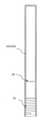
- FIG. 3 is a front shaft
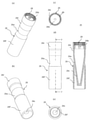
- FIG. 4 is a cap
- FIG. 5 is a rear shaft
- FIG. 6 is a component diagram of an inner front shaft.
- the applicator according to the first embodiment has a toe shaft 14 for mounting a coating liquid tank 12 for containing a liquid cosmetic to be supplied to the applicator body 10 and a toe shaft 14 from the rear.
- a first shaft 16 to be mounted and to cover the coating liquid tank 12 is provided, and a male screw portion 18 is provided on the outer periphery of the front shaft 14, and a first male screw portion 18 is located behind the male screw portion 18 and is formed along the circumferential direction.
- It has an engaging portion 20 (see FIG. 3), and has a female screw portion 22 for screwing to the male screw portion 18 and a first engaging portion 20 on the inner circumference of the rear shaft 16 (main body 16a).
- It has a second engaging portion 24 for engaging (see FIG. 5).
- the applicator includes a refill A in a state where the cap 26, the applicator body 10, the toe shaft 14, the inner toe shaft 34, the collector 36, and the coating liquid tank 12 are assembled. To.
- a cap 26 that can be attached to the front shaft to cover the coating body 10 is provided, a first protrusion 28 is formed on the inner surface of the cap 26, and a second protrusion 28 is formed on the outer peripheral surface of the front shaft 14.
- the protrusion 30 is formed and the cap 26 is attached to the front shaft 14, the first protrusion 28 and the second protrusion 30 are configured to be able to mesh with each other.
- the second protrusion 30 is formed on the end face of the flange portion 32 on the outer periphery of the toe shaft 14.
- the coating body 10 is mounted in the front end shaft 14 on the tip side via the inner tip shaft 34, and the liquid cosmetic is stored in the coating liquid tank 12 mounted on the rear end side of the front end shaft 14. To.
- the collector 36 is housed in the toe shaft 14, and the coating liquid tank 12 for storing the liquid cosmetics is mounted behind the collector 36.
- the flange portion 32 has an expanded diameter on the outer periphery of the front shaft 14, the cap 26 abuts on the front side surface of the flange portion 32, and the front end of the rear shaft 16 abuts on the rear side surface of the flange portion 32.
- the relay core 38 is arranged so as to penetrate the center of the axis of the collector 36.
- the relay core 38 guides the liquid cosmetic to the coating body 10.
- the front end portion of the applicator body 10 in the toe shaft 14 protrudes and is exposed from the opening 34b (see FIG. 6) of the inner toe shaft 34 at the tip of the toe shaft 14.
- the inner peripheral surface of the opening 34b of the inner tip shaft 34 is in contact with the outer periphery of the coating body 10.
- the tip of the relay core 38 in the collector 36 is inserted into the rear end of the coating body 10 to induce cosmetics, and the collector 36 has a liquid cosmetic guide groove (slit).
- the coating tool is designed so that the liquid cosmetic is guided from the relay core 38 to the coating body 10 via the relay core 38.
- the relay core 38 may have a derivative structure in which a fiber bundle or a resin-made liquid cosmetic guide groove is formed.
- the rear end portion of the coating body 10 has a hollow inside and a flange having an enlarged diameter formed on the outside.
- the tip of the relay core 38 is inserted inside the hollow.
- a collector 36 having a function of temporarily holding the liquid between a plurality of sheet sheets is arranged in the toe shaft 14.
- the flange portion 32 is pushed by the tip of the collector 36 and fixed in the toe shaft 14.
- the relay core 38 in the hollow hole 36a of the collector 36 has a structure that guides the liquid cosmetics in the coating liquid tank 12 to the coating body 10.
- the coating liquid tank 12 is fixed in the rear part of the toe shaft 14 by fitting the tip portion thereof.
- a hollow hole 36a along the axial direction is formed through the inside of the collector 36, and a relay core 38 is mounted in the hollow hole 36a.
- a plurality of single-wafered bodies 36b are arranged at intervals on the outer peripheral portion of the collector 36. It exerts the function of the collector 36 that temporarily stores the liquid between the sheet-fed bodies 36b by the capillary force.
- a slit (not shown) is formed so as to cut the sheet-fed body 36b in the vertical direction (axial direction).
- the collector 36 allows liquid cosmetics to flow in and out between the sheet-fed bodies 36b through the slits.
- a rib may be formed in the hollow hole 36a to support the relay core 38 with the rib.
- the collector 36 is mounted inside the toe shaft 14, and at the rear end portion of the collector 36, the hollow hole 36a and the slit face the opening at the front portion of the coating liquid tank 12.
- the rear end surface (rear end portion) of the relay core 38 mounted in the hollow hole 36a of the collector 36 is exposed to the coating liquid tank 12, and the relay core 38 moves the liquid (liquid cosmetic) in the coating liquid tank 12 forward. It is a configuration that guides toward (toward the coating body 10).
- the tip of the collector 36 has a cup shape, and the tip of the cup fits into the inner peripheral surface 34c formed inside the inner tip shaft 34 and is positioned in contact with the top 34a1 (see FIG. 6). Further, the rear end portion (rear end surface of the flange) of the coating body 10 is pressed by the cup-shaped tip portion of the collector 36. Further, the tip of the relay core 38 in the collector 36 is inserted into the rear end space of the coating body 10. The rear end portion of the collector 36 is exposed toward the coating liquid tank 12, and when the internal pressure of the coating liquid tank 12 rises due to an atmospheric pressure, a temperature change, or the like, the liquid cosmetic in the coating liquid tank 12 passes through the slit to the collector. It is reserved between the 36 sheet-fed bodies 36b.
- the toe shaft 14 is formed with a ventilation hole 14b for ventilating the inside and outside of the collector 36 for gas-liquid replacement.
- the outside air circulates from the ventilation hole 14b to the inside of the front shaft 14, and therefore, the outside air circulates to the single-wafer body 36b and the slit on the outer periphery of the collector 36 housed in the front shaft 14. Even if the internal pressure of the coating liquid tank 12 fluctuates, it is alleviated by the ventilation in the toe shaft 14 to prevent the liquid cosmetic from blowing out from the coating body 10 or the like, running out of the liquid cosmetic, or the like.
- the coating liquid tank 12 is fitted into the front portion of the coating liquid tank 12 into the rear portion (rear portion of the flange portion 32) of the front shaft 14 and mounted in the front shaft 14.
- the rear portion of the collector 36 is adjacent to the inside of the front portion of the coating liquid tank 12.
- the coating liquid tank 12 contains a metal or resin rod-shaped (possible shape such as a spherical shape) stirring body 12a for stirring the liquid together with the liquid (coating liquid).
- the toe shaft 14 has a substantially hollow cylindrical shape as a whole, and the tip portion is adjacent to the opening 14a and the rear peripheral surface portion is a passage for air replacement penetrating between the inner circumference and the outer circumference. Pore 14b is formed.
- a male screw portion 18 and a first engaging portion 20 located behind the male screw portion 18 and formed along the circumferential direction are provided.
- the flange portion 32 is configured by expanding the diameter of the flange portion 32 in the vicinity of the central portion, behind the ventilation hole 14b at the tip portion of the toe shaft 14.
- a rear portion extends in a cylindrical shape from the flange portion 32, and a male screw portion 18 is formed on the outer peripheral surface of the rear portion from a portion adjacent to the rear end surface of the flange portion 32 to a portion where about half of the rear portion is left.
- the male thread portion 18 has a convex male thread with a cut in the middle of the thread.
- the first engaging portion 20 has a structure in which protrusions are arranged in the circumferential direction in the vicinity of the rear end of the tubular rear portion of the front shaft 14 of the front shaft.
- Internal protrusions 14c are arranged in the circumferential direction on the inner peripheral surface of the rear end portion of the front shaft 14, and the internal protrusions 14c engage the coating liquid tank 12.
- the outer peripheral protrusion 14d in front of the outer peripheral surface of the front shaft 14 adjacent to the flange portion 32, there is a plate-shaped rib erected along the front and rear, and the end portion in the outer radial direction becomes thin.
- a plurality of second protrusions 30 are arranged in the circumferential direction to form protrusions.
- the second protrusion 30 has a structure in which it engages with and meshes with the first protrusion 28 formed on the inner peripheral surface of the rear end of the cap 26, and the cap 26 is fitted to the toe shaft 14. In the state, the structure is such that relative rotation is restricted.
- a step portion 14e for engaging the inner front shaft 34 is formed behind the opening 14a of the front shaft 14.
- An outer peripheral protrusion 14d having an uneven outer circumference is formed between the ventilation hole 14b of the leading shaft 14 and the flange portion 32. As shown in FIG. 4, the first outer peripheral protrusion 14d is engaged with the locking protrusion 26b of the cap 26 to prevent the cap 26 from coming off in the front-rear direction.
- the rear shaft 16 is fixed to the outer peripheral portion of the cylindrical main body 16a having a closed rear end by fitting or adhering a closed outer cylinder 16b at the rear end having a design on the outer surface. ing.
- a female screw portion 22 for screwing to the male screw portion 18 is formed in an inward thread shape on the inner circumference of the main body 16a of the rear shaft 16.
- a second engaging portion 24 for engaging with the first engaging portion 20 of the toe shaft 14 is formed behind the female screw portion 22.
- the second engaging portion 24 is formed with an annular protrusion (annular rib) protruding inwardly over the entire inner peripheral surface of the rear shaft 16 main body 16a.
- the second engaging portion 24 may have another structure such as an uneven portion as long as it is a structure that can be locked and fixed to the first engaging portion 20.
- the rear shaft 16 has a substantially cylindrical shape with its rear end closed.
- the liquid cosmetic applicator has a cap 26 that can be attached to the tip shaft 14 to cover the applicator body 10, and a first protrusion 28 is formed on the inner surface of the cap 26.
- a second protrusion 30 is formed on the outer peripheral surface of the front shaft 14, and when the cap 26 is attached to the front shaft 14, the first protrusion 28 and the second protrusion 30 are connected to each other.
- the second protrusion 30 is formed on the end surface of the flange 32 on the outer periphery of the toe shaft 14.
- a first protrusion 28 in which ribs along the front and rear are arranged in a plurality of circumferential directions is formed on the inner surface of the rear end portion.
- the second protrusion 30 is formed on the front end side surface of the flange 32 that protrudes in the outer diameter direction over the entire circumference of the outer circumference of the toe shaft 14.
- the second protrusion 30 is formed in a wall shape or a rib shape that is narrow and long in the axial direction.
- the first protrusion 28 and the second protrusion 30 are configured to be able to mesh with each other.
- the rear shaft 16 is rotated by holding the cap 26, the front shaft 14 rotates together with the cap 26 without shifting. Therefore, the rotation of the rear shaft 16 causes the rear shaft 14 to rotate with respect to the front shaft 14. 16 can be securely attached and detached.
- the cap 26 has a concave portion 26a formed on the outer peripheral surface thereof. That is, as shown in FIGS. 1 and 4, the concave portion 26a has a shape in which the outer peripheral surface of the central portion in the front-rear direction is recessed in a smaller diameter than the front portion 26f and the rear portion 26r, and the entire cap 26 is recessed. It is roughly like a drum.
- the cap 26 has an effect that the user can easily put his / her finger on the recess 26a of the cap 26, and it is easy to hold and attach / detach.
- the front portion 26f is a conical inner cylinder 26c that is continuously tapered and closed from the rear portion 26r, and has a cylindrical shape on the outside of the inner cylinder 26c, and the front portion 26f is integrally formed. Is.
- the cap 26 has a plurality of circumferential locking protrusions 26b on the inner peripheral portion thereof, adjacent to the first protrusion 28, and engaged with the outer peripheral protrusion 14d of the front shaft 14. Is formed. Therefore, if the locking protrusion 26b is locked and fixed to the outer peripheral protrusion 14d, the cap 26 is less likely to come off the front shaft 14, and the first protrusion 28 and the second protrusion 30 can maintain the meshed state. Therefore, the rear shaft 16 can be reliably attached and detached from the refill A.
- the cap 26 is a temporary cap when trading as a refill A, and after the refill A is attached to the rear axle 16 and replaced, the cap 26 is replaced with a decorative cap having a design on the outer peripheral surface from the beginning.
- the front shaft 14 is provided with an inner front shaft 34 on the inner circumference of the front shaft 14 so as to project from the opening 14a.
- the inner tip shaft 34 has a substantially cone-shaped tubular shape with an opening 34b at the tip open, and a triangular protruding top 34a1 facing backward is provided on the inner peripheral surface of the rear portion.
- the rib 34a to have is formed.
- a flat inner peripheral surface 34c is formed in a slightly tapered shape from the rear end of the inner tip shaft 34 to the inside, and the top portion 34a1 is formed so as to project in a stepped shape toward the inner circumference facing the inner peripheral surface 34c.
- an engagement step for engaging with the inner step portion (step portion 14e (see FIG. 3) adjacent to the opening 14a) of the tip shaft 14 near the central portion in the axial direction. 34d is formed.
- the coating body 10 is combed or guided by the top portion 34a1 of the rib 34a when the coating body 10 is attached at the time of assembly. Each fiber of 10 is guided into the inner tip shaft 34 without being disassembled, and the coating body 10 can be neatly attached without being reattached.
- the inner tip shaft 34 may be integrally molded with the tip shaft 14 by two-color molding or the like. It is preferable to use different colors for distinguishing the inner leading shaft 34 from the leading shaft 14.
- the liquid cosmetic contained in the coating liquid tank 12 preferably contains water, a water-soluble organic solvent, a film-forming agent, a coloring material, and a preservative as main components.
- the coloring material to be used at least one kind such as titanium oxide, iron oxide, konjo, and gunjo can be used.
- Titanium oxide has a specific gravity of 3.8 to 4.2
- the particle size in the cosmetic is preferably 200 to 500 nm
- iron oxide has a specific gravity of 3.8 to 5.5, which is a cosmetic.
- the particle size inside is preferably 90 to 600 nm
- the specific gravity of conjo is 1.8 to 1.9
- the particle size in cosmetics is preferably 80 to 300 nm
- the specific gravity of gunjo is.
- the particle size is 1.8 to 1.9
- the particle size in the cosmetic is preferably 300 to 600 nm.
- the "particle size” is a value obtained from a liquid cosmetic (25 ° C.) using a particle size measuring device FPAR-1000 (manufactured by Otsuka Electronics Co., Ltd.) by a dynamic light scattering method.
- Coloring materials that can be used include, for example, Blue No. 1 Al Lake, Red No. 202, Red No. 220, Red No. 226, Red No. 228, Blue No. 201, Blue No. 204, Blue No. 404, and Yellow No. 401. , Yellow No. 205, Yellow No. 4 Al Lake, Yellow No. 203 Al Lake, Red No. 104 Al Lake, Carbon Black, Carmine and other organic pigments, Red No. 2, Red No. 3 (FD & C Red No. 3), Red No. 40 No. (FD & C Red No. 40), Red No. 102, Red No. 104 (D & C Red No. 28), Red No. 105, Red No. 106, Red No. 201 (D & C Red No.
- Red No. 202 (D & C Red No. 6) .7), Red 203, Red 205, Red 227 (D & C Red No. 33), Red 230-1 (D & C Red No. 22), Red 401, Red 402, Red 504 (FD & C Red) No. 4), Orange 205 (D & C Orange No. 4), Orange 402, Yellow 4 (FD & C Yellow No. 5), Yellow 5 (FD & C Yellow No. 6), Yellow 203 (D & C Yellow No. 6). 10), Yellow 402, Yellow 403-1 (Ext.D & CYellow No.7), Yellow 406, Yellow 407, Green 3 (FD & C Green No.3), Green 201, Green 402, Blue 1 No. (FD & C Blue No.
- the color material is not particularly limited as long as it is used for water-based cosmetics.
- the content of these coloring materials is 0.05 to 30% of the total amount of liquid cosmetics in terms of color development, suitable viscosity, and smooth ejection property with a water-based cosmetic application tool equipped with an applicator. Is preferable, and more preferably 0.1 to 20%.
- the water-soluble organic solvent that can be used is not particularly limited as long as it is generally used in cosmetics, and any one can be used.
- any one can be used.
- ethanol, isopropanol, phenoxyethanol and the like can be mentioned.
- the content of these water-soluble organic solvents is preferably 0 to 20%, more preferably 8 to 15%, based on the total amount of the liquid cosmetics.
- the film-forming agent that can be used is, for example, an emulsion of a copolymer selected from one or more monomers among acrylic acid, methacrylic acid or an alkyl ester or derivative thereof, styrene, and vinyl acetate. Resin is mentioned.
- the content of these film-forming agents is preferably 2 to 15%, more preferably 2 to 10%, based on the total amount of liquid cosmetics in terms of solid content (resin content). ..
- the liquid cosmetic used uses water (including purified water, distilled water, ion-exchanged water, pure water, ultrapure water, etc.) as a solvent.
- the content of this water is the balance containing each of the above components and an optional component described later.
- liquid cosmetic to be used may contain optional ingredients and the like used in ordinary liquid cosmetics in addition to the above-mentioned ingredients and the like. Specifically, preservatives, antioxidants, neutralizers, ultraviolet absorbers, chelating agents, moisturizers, cosmetological ingredients, fragrances, viscosity modifiers, etc. are appropriately contained within a range that does not impair the effects of the present invention. be able to.
- the coating liquid is smoothly discharged from the coating tool, good coating performance is exhibited, and the like, and the temperature is 25 ° C. and the shearing speed is 76.6S -1 by the ELD type viscometer.
- the viscosity is preferably in the range of 2 to 9 mPa ⁇ s, and the surface tension of the liquid cosmetic is preferably 34 mN / m or more.
- the surface tension is a measured value obtained at a temperature of 25 ° C. using a CBVP-Z type tensiometer (plate method) manufactured by Kyowa Surface Chemistry.
- the refill A is configured with the cap 26, the coating body 10, the toe shaft 14, the inner toe shaft 34, the collector 36, the relay core 38, and the coating liquid tank 12 assembled. To. It can be sold on the market as a replacement refill A.
- the male screw portion 18 and the male screw portion 18 are located on the outer periphery of the toe shaft 14 and along the circumferential direction. It has a first engaging portion 20 formed, and engages with a female screw portion 22 for screwing into a male screw portion 18 and a first engaging portion 20 on the inner circumference of the rear shaft 16. Since it has a second engaging portion 24 for the purpose, when the female screw portion 22 of the rear shaft 16 is screwed into the male screw portion 18 of the front shaft 14, the first engaging portion 20 and the second engaging portion 20 are provided. Since they engage with each other when they get over the engaging portion 24, the user can easily determine that the rear shaft 16 is engaged with the front shaft 14 by feeling the engagement feeling, which is an excellent effect. Can play.
- the refill A is configured with the coating body 10, the leading shaft 14, the inner leading shaft 34, the collector 36, the relay core 38, and the coating liquid tank 12 assembled. It can be sold on the market as a replacement refill A.
- the rear shaft 16 is screwed in by holding the cap 26, the first protrusion 28 of the cap 26 is engaged with the second protrusion 30 of the front shaft 14 (see FIGS. 3 and 4). Since the relative rotation of the 26 is restricted with respect to the front shaft 14, the rear shaft 16 smoothly screws the front shaft 14, and the first engaging portion 20 is tightly engaged with the second engaging portion 24. The rear shaft 16 can be fully rotated until it is installed, and it can be mounted without error.
- FIG. 7 is an overall explanatory view of the applicator according to the second embodiment
- FIG. 8 is a component diagram of the toe shaft 14B
- FIG. 9 is a component diagram of the cap 26B.
- the applicator according to the second embodiment has the same reference numerals as those in the first embodiment.
- the coating tool includes a cap 26B, a coating body 10, a toe shaft 14B, a collector 36, and a refill B in which a coating liquid tank 12 is assembled.
- the overall configuration of the cap 26B and the partial configuration of the toe shaft 14B are different from the coating tool of the first embodiment, and the others are the same.
- the applicator has a cap 26B that can be attached to the front shaft 14B to cover the coating body 10, and the inner surface of the rear end portion (the side portion into which the front shaft 14B is fitted) of the cap 26B.
- the first protrusion 28B is formed on the front shaft 14B
- the second protrusion 30B is formed on the outer peripheral surface of the front shaft 14B
- the cap 26B is attached to the front shaft 14B
- the first protrusion 28B and the second protrusion are formed.
- the portions 30B are configured to be in mesh with each other and can be prevented from coming off.
- the second protrusion 30B is formed so as to extend from the front end surface of the flange portion 32 on the outer periphery of the front shaft 14B.
- the front shaft 14B is integrally formed up to the tip portion, and has the same structure as the inner front shaft 34 of the separate body of the first embodiment in the tip portion 14Bf of the front shaft 14B. Further, the first engaging portion 20B is formed in a rib shape long in the circumferential direction.
- the front shaft 14B has a substantially hollow cylindrical shape as a whole, and at the tip portion 14Bf, a vent hole for air replacement penetrating between the inner circumference and the outer circumference is provided in the peripheral surface portion whose diameter is expanded in a tapered shape rearward from the opening 14Ba at the tip portion. 14Bb is formed.
- the tip portion 14Bf has a hollow tapered structure in which the structure is integrated with the tip shaft 14B, similar to the inner tip shaft 34 of the first embodiment.
- a tapered positioning portion 14Bd is formed on the inner peripheral surface of the tip portion 14Bf, which is ahead of the step portion 14Bc, so that the cup-shaped tip portion of the collector 36 is inserted into the inner peripheral surface thereof together with the coating body 10 for positioning.
- a rib 34Ba having a triangular protruding top portion 34Ba1 facing rearward is formed on the inner peripheral surface in front of the positioning portion 14Bd.
- the outer periphery behind the flange portion 32 has a male screw portion 18B and a first engaging portion 20B located behind the male screw portion 18B and long formed along the circumferential direction. ..
- the male thread portion 18B is a convex male thread with no break in the middle of the thread.
- a plate-shaped rib erected along the front and rear, and the outer end portion in the outer diameter direction.
- a plurality of second protrusions 30B having a flat surface are arranged in the circumferential direction to form protrusions.
- the applicator has a cap 26B that can be attached to the tip shaft 14B to cover the coating body 10, and a first protrusion 28B is formed on the inner surface of the cap 26B to form the tip shaft.
- a second protrusion 30B is formed on the outer peripheral surface of the 14B, and when the cap 26B is attached to the front shaft 14B, the first protrusion 28B and the second protrusion 30B can mesh with each other, and the second protrusion 30B can be engaged with each other.
- the protrusion 30B of 2 is formed on the end surface of the flange 32 on the outer periphery of the toe shaft 14B.
- a first protrusion 28B in which ribs along the front and rear are arranged in a plurality of circumferential directions is formed on the inner surface of the rear end portion.
- the inner peripheral end 28Ba of the first protrusion 28B is formed in a flat hill shape. Therefore, when the cap 26B is attached to the toe shaft 14B, the first protrusion 28B and the second protrusion 30B are configured to be able to mesh with each other.
- the second protrusion 30 of the front shaft 14B engages with and meshes with the first protrusion 28B formed on the inner peripheral surface of the rear end of the cap 26B, and the cap 26B is fitted to the front shaft 14B.
- the structure is such that relative rotation is restricted.
- the inner peripheral end 28Ba of the first protrusion 28B is flat, and the second protrusion 30B of the front shaft 14B has a flat outer end in the outer diameter direction. Therefore, when the cap 26B is attached to the front shaft 14B, the opposite tip portions of the first protrusion 28B and the second protrusion 30B are configured to be flat, so that the first protrusion 28B and the first protrusion 28B and the second protrusion 30B are formed flat.
- the second protrusions 30B can easily ride on each other. If the relative rotation is performed after riding on the vehicle, the second protrusion 30B is easily fitted between the first protrusions 28B and the rotation is restricted. In addition, since it is easy to ride on and the force can be dispersed, it is possible to reliably prevent one or both of the first protrusion 28B and the second protrusion 30B from coming into contact with each other and causing damage such as chipping.
- the rear shaft 16 When replacing the refill B, if the rear shaft 16 is rotated by holding the cap 26B as in the case of the refill A, the front shaft 14B rotates together with the cap 26B without shifting. Therefore, the rotation of the rear shaft 16 causes the front shaft 16 to rotate.
- the rear shaft 16 can be reliably attached and detached to the 14B.
- the cap 26B has a concave portion 26Ba formed on its outer peripheral surface. That is, as shown in FIG. 9, the concave portion 26a has a shape in which the outer peripheral surface of the central portion in the front-rear direction is recessed in a diameter smaller than that of the front portion 26Bf and the rear portion 26Br, and the entire cap 26B has a substantially drum shape. Is presented.
- the concave portion 26Ba By forming the concave portion 26Ba, the cap 26B has an effect that the user can easily put his / her finger on the concave portion 26a of the cap 26B, which is easy to hold and attach / detach, as in the first embodiment.
- the cap 26B has a substantially drum shape as a whole.
- the inner cylinder 26c as in the first embodiment is not provided, and the shape is simplified.
- locking protrusions 26Bb for fixing that engage with the outer peripheral protrusion 14d of the front shaft 14B are arranged in a plurality of circumferential directions adjacent to the first protrusion 28B. It is formed. Further, as shown in FIG. 9, a rib 26Be long in the axial direction is erected on the inner peripheral surface at the tip of the locking projection 26Bb, and as shown in FIG. 7, when the cap 26B is fitted to the front shaft.
- the front shaft 14B can be supported from the surroundings to prevent the cap 26B from rattling.
- the coating tool of the present invention can be used as a coating tool for a coating liquid.
- Coating body 12 Coating liquid tank 14 Front shaft 14c Internal protrusion 14d Outer protrusion 14e Step part 14B Front shaft 14Bf Tip part 16 Rear shaft 16a Main body 16b Exterior cylinder 18 Male threaded part 18B Male threaded part 20 First engaging part 20B No.
Landscapes
- Coating Apparatus (AREA)
Priority Applications (5)
| Application Number | Priority Date | Filing Date | Title |
|---|---|---|---|
| KR1020237008376A KR20230054392A (ko) | 2020-08-21 | 2021-08-19 | 도포구 |
| JP2022544006A JPWO2022039243A1 (https=) | 2020-08-21 | 2021-08-19 | |
| US18/021,614 US12144412B2 (en) | 2020-08-21 | 2021-08-19 | Applicator |
| CN202180055893.8A CN116056802A (zh) | 2020-08-21 | 2021-08-19 | 涂布器 |
| EP21858386.2A EP4201252A4 (en) | 2020-08-21 | 2021-08-19 | APPLICATOR |
Applications Claiming Priority (2)
| Application Number | Priority Date | Filing Date | Title |
|---|---|---|---|
| JP2020-139994 | 2020-08-21 | ||
| JP2020139994 | 2020-08-21 |
Publications (1)
| Publication Number | Publication Date |
|---|---|
| WO2022039243A1 true WO2022039243A1 (ja) | 2022-02-24 |
Family
ID=80323507
Family Applications (1)
| Application Number | Title | Priority Date | Filing Date |
|---|---|---|---|
| PCT/JP2021/030471 Ceased WO2022039243A1 (ja) | 2020-08-21 | 2021-08-19 | 塗布具 |
Country Status (6)
| Country | Link |
|---|---|
| US (1) | US12144412B2 (https=) |
| EP (1) | EP4201252A4 (https=) |
| JP (1) | JPWO2022039243A1 (https=) |
| KR (1) | KR20230054392A (https=) |
| CN (1) | CN116056802A (https=) |
| WO (1) | WO2022039243A1 (https=) |
Families Citing this family (1)
| Publication number | Priority date | Publication date | Assignee | Title |
|---|---|---|---|---|
| KR102899132B1 (ko) * | 2023-05-11 | 2025-12-17 | 임프주식회사 | 휴대용 미용액 충전 튜브 캡 결합용 지그 |
Citations (9)
| Publication number | Priority date | Publication date | Assignee | Title |
|---|---|---|---|---|
| US4289248A (en) * | 1979-10-15 | 1981-09-15 | Becton, Dickinson And Company | Container closure assembly having intermediate positioning means |
| JPS60148461A (ja) * | 1983-10-13 | 1985-08-05 | ロレアル | びん |
| JP2003054181A (ja) * | 2001-08-15 | 2003-02-26 | Mitsubishi Pencil Co Ltd | 筆記具および筆記具のシール部の形成方法 |
| JP3133495U (ja) * | 2007-05-01 | 2007-07-12 | パイロットインキ株式会社 | インキタンク交換式筆記具 |
| JP2011135928A (ja) * | 2009-12-25 | 2011-07-14 | Kao Corp | 塗布具 |
| JP2015165866A (ja) * | 2014-03-04 | 2015-09-24 | 鈴野化成株式会社 | カートリッジ式化粧料容器 |
| JP2018192242A (ja) | 2017-05-16 | 2018-12-06 | 三菱鉛筆株式会社 | 塗布具 |
| JP2020001193A (ja) * | 2018-06-25 | 2020-01-09 | 株式会社パイロットコーポレーション | 熱変色性筆記具 |
| JP2020023118A (ja) * | 2018-08-07 | 2020-02-13 | 三菱鉛筆株式会社 | 塗布具 |
Family Cites Families (7)
| Publication number | Priority date | Publication date | Assignee | Title |
|---|---|---|---|---|
| FR2520328A1 (fr) * | 1982-01-22 | 1983-07-29 | Chanel | Dispositif pour eviter l'auto-devissage d'un bouchon sur un flacon |
| AU9650098A (en) * | 1997-12-25 | 1999-07-19 | Mitsubishi Pencil Kabushiki Kaisha | Ball-point pen |
| JP3420078B2 (ja) * | 1998-09-02 | 2003-06-23 | タチカワ株式会社 | 筆記具 |
| CN100477939C (zh) * | 2004-04-28 | 2009-04-15 | 株式会社吉野工业所 | 液体涂覆用具 |
| JP5078505B2 (ja) * | 2007-08-28 | 2012-11-21 | アサヌマ コーポレーション株式会社 | 液体塗布部材 |
| JP7401175B2 (ja) * | 2017-05-16 | 2023-12-19 | 三菱鉛筆株式会社 | 塗布具 |
| JP7350487B2 (ja) | 2019-01-23 | 2023-09-26 | 三菱鉛筆株式会社 | 化粧料塗布具 |
-
2021
- 2021-08-19 KR KR1020237008376A patent/KR20230054392A/ko active Pending
- 2021-08-19 US US18/021,614 patent/US12144412B2/en active Active
- 2021-08-19 JP JP2022544006A patent/JPWO2022039243A1/ja active Pending
- 2021-08-19 EP EP21858386.2A patent/EP4201252A4/en active Pending
- 2021-08-19 WO PCT/JP2021/030471 patent/WO2022039243A1/ja not_active Ceased
- 2021-08-19 CN CN202180055893.8A patent/CN116056802A/zh active Pending
Patent Citations (9)
| Publication number | Priority date | Publication date | Assignee | Title |
|---|---|---|---|---|
| US4289248A (en) * | 1979-10-15 | 1981-09-15 | Becton, Dickinson And Company | Container closure assembly having intermediate positioning means |
| JPS60148461A (ja) * | 1983-10-13 | 1985-08-05 | ロレアル | びん |
| JP2003054181A (ja) * | 2001-08-15 | 2003-02-26 | Mitsubishi Pencil Co Ltd | 筆記具および筆記具のシール部の形成方法 |
| JP3133495U (ja) * | 2007-05-01 | 2007-07-12 | パイロットインキ株式会社 | インキタンク交換式筆記具 |
| JP2011135928A (ja) * | 2009-12-25 | 2011-07-14 | Kao Corp | 塗布具 |
| JP2015165866A (ja) * | 2014-03-04 | 2015-09-24 | 鈴野化成株式会社 | カートリッジ式化粧料容器 |
| JP2018192242A (ja) | 2017-05-16 | 2018-12-06 | 三菱鉛筆株式会社 | 塗布具 |
| JP2020001193A (ja) * | 2018-06-25 | 2020-01-09 | 株式会社パイロットコーポレーション | 熱変色性筆記具 |
| JP2020023118A (ja) * | 2018-08-07 | 2020-02-13 | 三菱鉛筆株式会社 | 塗布具 |
Non-Patent Citations (1)
| Title |
|---|
| See also references of EP4201252A4 |
Also Published As
| Publication number | Publication date |
|---|---|
| EP4201252A1 (en) | 2023-06-28 |
| KR20230054392A (ko) | 2023-04-24 |
| US20230292910A1 (en) | 2023-09-21 |
| US12144412B2 (en) | 2024-11-19 |
| JPWO2022039243A1 (https=) | 2022-02-24 |
| EP4201252A4 (en) | 2024-08-21 |
| CN116056802A (zh) | 2023-05-02 |
Similar Documents
| Publication | Publication Date | Title |
|---|---|---|
| US11084316B2 (en) | Applicator | |
| JPH09322819A (ja) | 塗布具 | |
| KR20090027340A (ko) | 액체 화장료용 도포구 | |
| US3446563A (en) | Fiber-tip writing pen with replaceable cartridge | |
| US20030063942A1 (en) | Coating applicator and method of using the same | |
| KR101274866B1 (ko) | 화장용 아이라이너 용기 | |
| JP2018192242A (ja) | 塗布具 | |
| WO2022039243A1 (ja) | 塗布具 | |
| JP7394199B2 (ja) | 化粧料塗布具 | |
| JP2004082693A (ja) | カートリッジ式塗布具 | |
| JP2006346975A (ja) | 塗布具 | |
| JP6549473B2 (ja) | 塗布具 | |
| JPH0739804A (ja) | ボールペン型塗布具用チップ | |
| JPH0116540Y2 (https=) | ||
| JP2604419Y2 (ja) | 塗布具 | |
| JP2602464Y2 (ja) | 液体塗布具 | |
| JP2004142255A (ja) | 筆記具 | |
| JP7430454B2 (ja) | 液体吐出具 | |
| JP6745387B2 (ja) | 塗布具 | |
| JP2025118525A (ja) | 化粧料塗布具 | |
| JPH0753747Y2 (ja) | 弁付塗布具 | |
| WO2025258587A1 (ja) | 塗布具 | |
| WO2024029380A1 (ja) | 化粧料塗布具 | |
| WO2025053263A1 (ja) | 塗布具 | |
| JP2024010516A (ja) | インク用包装容器 |
Legal Events
| Date | Code | Title | Description |
|---|---|---|---|
| 121 | Ep: the epo has been informed by wipo that ep was designated in this application |
Ref document number: 21858386 Country of ref document: EP Kind code of ref document: A1 |
|
| ENP | Entry into the national phase |
Ref document number: 2022544006 Country of ref document: JP Kind code of ref document: A |
|
| ENP | Entry into the national phase |
Ref document number: 20237008376 Country of ref document: KR Kind code of ref document: A |
|
| NENP | Non-entry into the national phase |
Ref country code: DE |
|
| ENP | Entry into the national phase |
Ref document number: 2021858386 Country of ref document: EP Effective date: 20230321 |