WO2022038759A1 - レーダ装置 - Google Patents
レーダ装置 Download PDFInfo
- Publication number
- WO2022038759A1 WO2022038759A1 PCT/JP2020/031552 JP2020031552W WO2022038759A1 WO 2022038759 A1 WO2022038759 A1 WO 2022038759A1 JP 2020031552 W JP2020031552 W JP 2020031552W WO 2022038759 A1 WO2022038759 A1 WO 2022038759A1
- Authority
- WO
- WIPO (PCT)
- Prior art keywords
- antenna
- antennas
- receiving
- group
- transmitting
- Prior art date
- Legal status (The legal status is an assumption and is not a legal conclusion. Google has not performed a legal analysis and makes no representation as to the accuracy of the status listed.)
- Ceased
Links
Images




















Classifications
-
- H—ELECTRICITY
- H01—ELECTRIC ELEMENTS
- H01Q—ANTENNAS, i.e. RADIO AERIALS
- H01Q1/00—Details of, or arrangements associated with, antennas
- H01Q1/52—Means for reducing coupling between antennas; Means for reducing coupling between an antenna and another structure
- H01Q1/521—Means for reducing coupling between antennas; Means for reducing coupling between an antenna and another structure reducing the coupling between adjacent antennas
- H01Q1/525—Means for reducing coupling between antennas; Means for reducing coupling between an antenna and another structure reducing the coupling between adjacent antennas between emitting and receiving antennas
-
- H—ELECTRICITY
- H01—ELECTRIC ELEMENTS
- H01Q—ANTENNAS, i.e. RADIO AERIALS
- H01Q21/00—Antenna arrays or systems
- H01Q21/06—Arrays of individually energised antenna units similarly polarised and spaced apart
- H01Q21/061—Two dimensional planar arrays
-
- G—PHYSICS
- G01—MEASURING; TESTING
- G01S—RADIO DIRECTION-FINDING; RADIO NAVIGATION; DETERMINING DISTANCE OR VELOCITY BY USE OF RADIO WAVES; LOCATING OR PRESENCE-DETECTING BY USE OF THE REFLECTION OR RERADIATION OF RADIO WAVES; ANALOGOUS ARRANGEMENTS USING OTHER WAVES
- G01S13/00—Systems using the reflection or reradiation of radio waves, e.g. radar systems; Analogous systems using reflection or reradiation of waves whose nature or wavelength is irrelevant or unspecified
- G01S13/02—Systems using reflection of radio waves, e.g. primary radar systems; Analogous systems
- G01S13/06—Systems determining position data of a target
- G01S13/08—Systems for measuring distance only
- G01S13/32—Systems for measuring distance only using transmission of continuous waves, whether amplitude-, frequency-, or phase-modulated, or unmodulated
- G01S13/34—Systems for measuring distance only using transmission of continuous waves, whether amplitude-, frequency-, or phase-modulated, or unmodulated using transmission of continuous, frequency-modulated waves while heterodyning the received signal, or a signal derived therefrom, with a locally-generated signal related to the contemporaneously transmitted signal
- G01S13/343—Systems for measuring distance only using transmission of continuous waves, whether amplitude-, frequency-, or phase-modulated, or unmodulated using transmission of continuous, frequency-modulated waves while heterodyning the received signal, or a signal derived therefrom, with a locally-generated signal related to the contemporaneously transmitted signal using sawtooth modulation
-
- G—PHYSICS
- G01—MEASURING; TESTING
- G01S—RADIO DIRECTION-FINDING; RADIO NAVIGATION; DETERMINING DISTANCE OR VELOCITY BY USE OF RADIO WAVES; LOCATING OR PRESENCE-DETECTING BY USE OF THE REFLECTION OR RERADIATION OF RADIO WAVES; ANALOGOUS ARRANGEMENTS USING OTHER WAVES
- G01S13/00—Systems using the reflection or reradiation of radio waves, e.g. radar systems; Analogous systems using reflection or reradiation of waves whose nature or wavelength is irrelevant or unspecified
- G01S13/02—Systems using reflection of radio waves, e.g. primary radar systems; Analogous systems
- G01S13/06—Systems determining position data of a target
- G01S13/42—Simultaneous measurement of distance and other co-ordinates
- G01S13/44—Monopulse radar, i.e. simultaneous lobing
-
- G—PHYSICS
- G01—MEASURING; TESTING
- G01S—RADIO DIRECTION-FINDING; RADIO NAVIGATION; DETERMINING DISTANCE OR VELOCITY BY USE OF RADIO WAVES; LOCATING OR PRESENCE-DETECTING BY USE OF THE REFLECTION OR RERADIATION OF RADIO WAVES; ANALOGOUS ARRANGEMENTS USING OTHER WAVES
- G01S13/00—Systems using the reflection or reradiation of radio waves, e.g. radar systems; Analogous systems using reflection or reradiation of waves whose nature or wavelength is irrelevant or unspecified
- G01S13/02—Systems using reflection of radio waves, e.g. primary radar systems; Analogous systems
- G01S13/50—Systems of measurement based on relative movement of target
- G01S13/58—Velocity or trajectory determination systems; Sense-of-movement determination systems
- G01S13/583—Velocity or trajectory determination systems; Sense-of-movement determination systems using transmission of continuous unmodulated waves, amplitude-, frequency-, or phase-modulated waves and based upon the Doppler effect resulting from movement of targets
- G01S13/584—Velocity or trajectory determination systems; Sense-of-movement determination systems using transmission of continuous unmodulated waves, amplitude-, frequency-, or phase-modulated waves and based upon the Doppler effect resulting from movement of targets adapted for simultaneous range and velocity measurements
-
- G—PHYSICS
- G01—MEASURING; TESTING
- G01S—RADIO DIRECTION-FINDING; RADIO NAVIGATION; DETERMINING DISTANCE OR VELOCITY BY USE OF RADIO WAVES; LOCATING OR PRESENCE-DETECTING BY USE OF THE REFLECTION OR RERADIATION OF RADIO WAVES; ANALOGOUS ARRANGEMENTS USING OTHER WAVES
- G01S13/00—Systems using the reflection or reradiation of radio waves, e.g. radar systems; Analogous systems using reflection or reradiation of waves whose nature or wavelength is irrelevant or unspecified
- G01S13/88—Radar or analogous systems specially adapted for specific applications
- G01S13/93—Radar or analogous systems specially adapted for specific applications for anti-collision purposes
- G01S13/931—Radar or analogous systems specially adapted for specific applications for anti-collision purposes of land vehicles
-
- G—PHYSICS
- G01—MEASURING; TESTING
- G01S—RADIO DIRECTION-FINDING; RADIO NAVIGATION; DETERMINING DISTANCE OR VELOCITY BY USE OF RADIO WAVES; LOCATING OR PRESENCE-DETECTING BY USE OF THE REFLECTION OR RERADIATION OF RADIO WAVES; ANALOGOUS ARRANGEMENTS USING OTHER WAVES
- G01S7/00—Details of systems according to groups G01S13/00, G01S15/00, G01S17/00
- G01S7/02—Details of systems according to groups G01S13/00, G01S15/00, G01S17/00 of systems according to group G01S13/00
- G01S7/03—Details of HF subsystems specially adapted therefor, e.g. common to transmitter and receiver
-
- H—ELECTRICITY
- H01—ELECTRIC ELEMENTS
- H01Q—ANTENNAS, i.e. RADIO AERIALS
- H01Q1/00—Details of, or arrangements associated with, antennas
- H01Q1/27—Adaptation for use in or on movable bodies
- H01Q1/32—Adaptation for use in or on road or rail vehicles
- H01Q1/3208—Adaptation for use in or on road or rail vehicles characterised by the application wherein the antenna is used
- H01Q1/3233—Adaptation for use in or on road or rail vehicles characterised by the application wherein the antenna is used particular used as part of a sensor or in a security system, e.g. for automotive radar, navigation systems
Definitions
- This application relates to a radar device.
- Patent Document 1 As a conventional radar device, for example, there is a radar system described in Patent Document 1.
- the configuration and operation of the conventional radar device described in Patent Document 1 are as follows.
- the conventional radar device described in Patent Document 1 detects an object around an automobile to be detected, that is, a target object.
- a transmitting means composed of at least one transmitting antenna radiates a transmitting signal to an object.
- the receiving means composed of at least one receiving antenna receives the reflected signal, which is the transmitted signal reflected by the object.
- the signal processing means processes the received signal received by the receiving means.
- the received signal is acquired by a different combination of the transmitting antenna and the receiving antenna. For each combination, a relative phase center defined as the sum of the vector from the reference point to the phase center of the transmitting antenna and the vector from the reference point to the phase center of the receiving antenna is obtained.
- each transmitting antenna has at least approximately the same radiation characteristics as each other.
- each receiving antenna has at least approximately the same radiation characteristics as each other.
- the radiation characteristics of the transmitting antenna and the radiation characteristics of the receiving antenna may be different from each other.
- a certain spatial direction S is a direction perpendicular to the spatial direction R.
- the spatial direction S is, for example, the vertical direction
- the spatial direction R is, for example, the horizontal direction.
- phase component of the received signal of the object alternates with a period length P according to the angular position of the received signal with respect to the spatial direction S. Therefore, by using the phase component, the position of the object in the spatial direction S can be represented.
- the phase center spacing of the receiving antenna having a plurality of element antennas is arranged at ⁇ / 2, and power is applied to each element antenna.
- the feeding circuit for feeding power is a skewered feeding circuit that is not arranged between each receiving antenna.
- the wiring lengths of the feeding circuits to the element antennas constituting the receiving antenna are not equal, the equiphase distribution cannot be realized, and the antenna frequency characteristic having a wide band, that is, the antenna frequency characteristic having a wide band. Cannot be realized.
- an automobile radar uses a band of 76 to 81 GHz, but the conventional radar device of Patent Document 1 has a limit in realizing a wide band antenna having a specific band exceeding 2%, and has a bandwidth.
- Other feeding methods are suitable for realizing a wideband antenna with a specific band of 2% or more.
- the specific band is defined as A% of the frequency of the transmission signal, and when the frequency of the transmission signal is 77 GHz and the specific band is 2%, the bandwidth of the antenna is about 1.5 GHz.
- the bandwidth of the antenna is defined by, for example, a bandwidth such that the reflection is equal to or less than a predetermined value.
- the bandwidth of the antenna is defined so that the reflection is, for example, -10 dB or less.
- the upper limit of the specific band is limited not only by the feeding method but also by the bandwidth of the element antenna constituting the antenna. For example, the upper limit of the specific band is about 10%.
- a parallel feeding method tournament method
- the parallel feeding system feeding circuit spreads in the lateral direction (adjacent antenna direction) as the number of element antennas constituting one receiving antenna or transmitting antenna increases, and the antennas can be arranged only at wide intervals. For example, when the frequency is 77 GHz, the wavelength ⁇ is about 3.9 mm.
- the conventional radar device of Patent Document 1 when a parallel feeding system feeding circuit is adopted, if the installation space of the feeding circuit becomes large, the receiving antennas are arranged at a phase center interval wider than ⁇ / 2.
- the receiving antenna cannot be arranged at the phase center spacing of ⁇ / 2. For example, if the receiving antennas cannot be arranged at the phase center spacing of ⁇ / 2, high side lobes or grating lobes will be generated within the desired coverage (field of view), and the detection target will be erroneously detected. It may end up. Even if the power feeding circuit is not a parallel power feeding system, even when power is supplied to each element antenna from the lateral direction (adjacent antenna direction), the detection target may be erroneously detected.
- the desired field of view is the field of view set by design, i.e. the designed field of view.
- this distance d is determined according to the setting of the visual field range, that is, the range of the angle ⁇ that can be measured. For example, when the angle ⁇ is ⁇ 90 ° or more and 90 ° or less, the distance d needs to be in the range of greater than 0 and ⁇ / 2 or less.
- the conventional radar device of Patent Document 1 has a predetermined distance d while maintaining an angle ⁇ of ⁇ 90 ° or more and 90 ° or less when a feeding circuit for feeding power from the lateral direction such as a parallel feeding method is adopted. It is not possible to arrange receiving antennas of 3 or more channels at intervals.
- the technique disclosed in the present specification is a radar device capable of reducing side lobes and suppressing erroneous detection even when receiving antennas of three or more channels or receiving antennas cannot be physically arranged at predetermined distance intervals.
- the purpose is to provide.
- An example radar device disclosed in the present specification receives a plurality of transmitting antennas that radiate a transmission signal toward a target object and a reflected signal that is reflected by the target object and outputs the transmission signal as a reception signal. It includes a plurality of receiving antennas and a processing unit that processes received signals output from each of the plurality of receiving antennas. It is a group of antennas having either a plurality of transmitting antennas or a plurality of receiving antennas, with the antenna spacing between adjacent antennas as the basic distance, which is determined based on the viewing range required for the radar device, and is adjacent to each other.
- the first antenna group is a group of antennas having a first antenna set having a plurality of first antennas having a basic distance between the antennas, and the other plurality of antennas different from the first antenna of the first antenna group are provided.
- the second antenna group is a group of antennas having a second antenna set having a plurality of second antennas in which the antenna spacing between adjacent antennas is twice the basic distance.
- the first antenna and the second antenna include a plurality of element antennas and a feeding circuit for supplying electric power to the element antennas.
- the plurality of first antennas are arranged side by side in the first arrangement direction perpendicular to the transmission direction of the transmission signal, and have their respective feeding circuits on the positive side or the negative side of the first arrangement direction.
- the plurality of second antennas are arranged side by side in the second arrangement direction perpendicular to the transmission direction of the transmission signal and parallel to the first arrangement direction, and have a feeding circuit on the positive side or the negative side of the second arrangement direction. There is. No feeding circuit is arranged between adjacent antennas in the first antenna set.
- the virtual receiving antenna group composed of a plurality of virtual receiving antennas formed by a plurality of first antennas of the first antenna group and a plurality of second antennas of the second antenna group is the first antenna group perpendicular to the transmitting direction of the transmitted signal. They are arranged side by side in the arrangement direction and the third arrangement direction parallel to the second arrangement direction, and the distance between adjacent virtual receiving antennas in the third arrangement direction is the basic distance.
- An example radar device disclosed in the present specification includes a first antenna set having a plurality of first antennas in which the antenna spacing between antennas adjacent to the first antenna group is a basic distance, and the second antenna group is adjacent to each other.
- FIG. It is a figure which shows the structure of the radar apparatus which concerns on Embodiment 1.
- FIG. It is a figure which shows the example of the hardware configuration which realizes the function of the processing part of FIG.
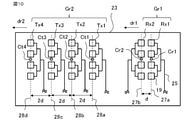
- FIG. It is a figure which shows the 1st example of the antenna arrangement of the radar apparatus which concerns on Embodiment 1.
- FIG. It is a figure which shows the detail of the antenna arrangement of FIG. It is a figure explaining the angle measuring method of the radar apparatus which concerns on Embodiment 1.
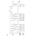
- FIG. It is a figure which shows an example of the modulation pattern of the radar apparatus which concerns on Embodiment 1.
- FIG. It is a figure which shows the virtual receiving antenna group corresponding to the antenna arrangement of FIG. It is a flowchart which shows the processing of the radar apparatus which concerns on Embodiment 1.
- FIG. It is a figure which shows the 2nd example of the antenna arrangement of the radar apparatus which concerns on Embodiment 1.
- FIG. It is a figure which shows the detail of the antenna arrangement of FIG. It is a figure which shows the virtual receiving antenna group corresponding to the antenna arrangement of FIG. It is a figure which shows the 3rd example of the antenna arrangement of the radar apparatus which concerns on Embodiment 1.
- FIG. It is a figure which shows the 1st example of the virtual receiving antenna group corresponding to the antenna arrangement of FIG.
- FIG. It is a figure which shows the 2nd example of the virtual receiving antenna group corresponding to the antenna arrangement of FIG.
- FIG. 1st example of the antenna of the radar apparatus which concerns on Embodiment 1.
- FIG. It is a figure which shows the 2nd example of the antenna of the radar apparatus which concerns on Embodiment 1.
- FIG. It is a figure which shows the 3rd example of the antenna of the radar apparatus which concerns on Embodiment 1.
- FIG. It is a figure which shows the 4th example of the antenna of the radar apparatus which concerns on Embodiment 1.
- FIG. It is a figure which shows the 5th example of the antenna of the radar apparatus which concerns on Embodiment 1.
- FIG. It is a figure which shows the sixth example of the antenna of the radar apparatus which concerns on Embodiment 1.
- FIG. It is a figure which shows the 4th example of the antenna arrangement of the radar apparatus which concerns on Embodiment 1.
- FIG. It is a figure which shows the virtual receiving antenna group corresponding to the antenna arrangement of FIG.
- FIG. 1 It is a figure which shows the 5th example of the antenna arrangement of the radar apparatus which concerns on Embodiment 1.
- FIG. It is a figure which shows the sixth example of the antenna arrangement of the radar apparatus which concerns on Embodiment 1.
- FIG. It is a figure which shows the virtual receiving antenna group corresponding to the antenna arrangement of FIG. It is a figure which shows the antenna arrangement of the radar apparatus which concerns on Embodiment 2.
- FIG. It is a figure which shows the virtual receiving antenna group corresponding to the antenna arrangement of FIG. It is a figure which shows the antenna arrangement of the radar apparatus which concerns on Embodiment 3.
- FIG. 1 shows the 5th example of the antenna arrangement of the radar apparatus which concerns on Embodiment 1.
- FIG. It is a figure which shows the sixth example of the antenna arrangement of the radar apparatus which concerns on Embodiment 1.
- FIG. It is a figure which shows the 7th
- FIG. 37 It is a figure which shows the arrangement of the transmitting antenna of FIG. It is a figure which shows the virtual receiving antenna group corresponding to the antenna arrangement of FIG. It is a figure which shows the antenna arrangement of the radar apparatus which concerns on Embodiment 4.
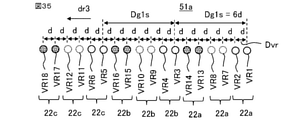
- FIG. It is a figure which shows the arrangement of the transmitting antenna of FIG. 32. It is a figure which shows the virtual receiving antenna group corresponding to the antenna arrangement of FIG. 32. It is a figure which shows the 1st virtual receiving antenna group of FIG. 34. It is a figure which shows the 2nd virtual receiving antenna group of FIG. It is a figure which shows the antenna arrangement of the radar apparatus which concerns on Embodiment 5. It is a figure which shows the virtual receiving antenna group corresponding to the antenna arrangement of FIG. 37.
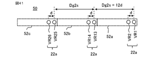
- FIG. 37 It is a figure which shows the 3rd virtual receiving antenna group of FIG. 37. It is a figure which shows the antenna arrangement of the radar apparatus which concerns on Embodiment 6. It is a figure which shows the virtual receiving antenna group corresponding to the antenna arrangement of FIG. 40. It is a figure which shows the 1st virtual receiving antenna group of FIG. 41. It is a figure which shows the 2nd virtual receiving antenna group of FIG. 41. It is a figure which shows the 3rd virtual receiving antenna group of FIG. 41.
- FIG. 1 is a diagram showing a configuration of a radar device according to the first embodiment
- FIG. 2 is a diagram showing an example of a hardware configuration that realizes the function of the processing unit of FIG.
- FIG. 3 is a diagram showing a first example of an antenna arrangement of the radar device according to the first embodiment
- FIG. 4 is a diagram showing details of the antenna arrangement of FIG.
- FIG. 5 is a diagram illustrating a method of measuring an angle of the radar device according to the first embodiment
- FIG. 6 is a diagram showing an example of a modulation pattern of the radar device according to the first embodiment.
- FIG. 7 is a diagram showing a virtual receiving antenna group corresponding to the antenna arrangement of FIG. 3, and FIG.
- FIG. 8 is a flowchart showing processing of the radar device according to the first embodiment.
- FIG. 9 is a diagram showing a second example of antenna arrangement of the radar device according to the first embodiment.
- 10 is a diagram showing the details of the antenna arrangement of FIG. 9, and
- FIG. 11 is a diagram showing a virtual receiving antenna group corresponding to the antenna arrangement of FIG. 9.
- FIG. 12 is a diagram showing a third example of antenna arrangement of the radar device according to the first embodiment.
- 13 is a diagram showing a first example of a virtual receiving antenna group corresponding to the antenna arrangement of FIG. 12, and
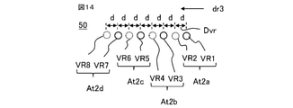
- FIG. 14 is a diagram showing a second example of a virtual receiving antenna group corresponding to the antenna arrangement of FIG. 12.
- FIG. 9 is a diagram showing a second example of antenna arrangement of the radar device according to the first embodiment.
- 10 is a diagram showing the details of the antenna arrangement of FIG. 9
- FIG. 11 is a diagram showing a virtual receiving antenna group corresponding to the antenna arrangement of FIG. 9.
- FIG. 15 is a diagram showing a first example of the antenna of the radar device according to the first embodiment
- FIG. 16 is a diagram showing a second example of the antenna of the radar device according to the first embodiment
- FIG. 17 is a diagram showing a third example of the antenna of the radar device according to the first embodiment
- FIG. 18 is a diagram showing a fourth example of the antenna of the radar device according to the first embodiment
- FIG. 19 is a diagram showing a fifth example of the antenna of the radar device according to the first embodiment
- FIG. 20 is a diagram showing a sixth example of the antenna of the radar device according to the first embodiment.
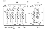
- FIG. 21 is a diagram showing a fourth example of the antenna arrangement of the radar device according to the first embodiment
- FIG. 22 is a diagram showing a virtual receiving antenna group corresponding to the antenna arrangement of FIG. 21.
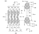
- FIG. 23 is a diagram showing a fifth example of the antenna arrangement of the radar device according to the first embodiment
- FIG. 24 is a diagram showing a sixth example of the antenna arrangement of the radar device according to the first embodiment.
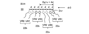
- FIG. 25 is a diagram showing a seventh example of the antenna arrangement of the radar device according to the first embodiment
- FIG. 26 is a diagram showing a virtual receiving antenna group corresponding to the antenna arrangement of FIG. 25.
- the same or corresponding configurations are designated by the same reference numerals, and duplicate description will be omitted.
- the radar device 1 of the first embodiment includes a processing unit 11, a transmitting circuit 12, a receiving circuit 13, a plurality of transmitting antennas Tx1, Tx2, and a plurality of receiving antennas Rx1, Rx2, Rx3, and Rx4.
- a structural unit such as Tx1, Tx2, Rx1, Rx2, Rx3, and Rx4 that is processed as one antenna is referred to as a channel.
- the transmitting antennas Tx1 and Tx2 are collectively referred to, the transmitting antenna Tx is referred to, and similarly, when the receiving antennas Rx1, Rx2, Rx3, and Rx4 are collectively referred to, the receiving antenna Rx is referred to.
- the radar device 1 is mounted on a moving body.
- the radar device 1 is connected to the ECU (Electronic Control Unit) 2 of the vehicle.
- ECU Electronic Control Unit
- the antenna distance D1 between adjacent antennas is a predetermined basic distance d. It suffices to have a configuration in which the first antennas At1a and At1b, which are the two transmitting antennas or receiving antennas arranged in the above, are provided, and the second antenna operating in the opposite direction to the first antenna has an arbitrary number of channels of 2 or more.
- FIG. 12 shows an example in which four second antennas At2a, At2b, At2c, and At2d are provided.
- the first antennas At1a and At1b are collectively referred to, they are referred to as the first antenna At1
- the second antennas At2a, At2b, At2c and At2d are collectively referred to, they are referred to as the second antenna At2.
- the radar device 1 radiates the transmission signal generated by the transmission circuit 12 from the transmission antenna Tx1 or the transmission antenna Tx2 toward the target object 33 (see FIG. 5).
- the transmission signal is reflected by the target object 33, which is the detection target.
- the reflected signal which is a reflected signal, is received by the receiving antenna Rx.
- the received signal is input to the processing unit 11 as a reception signal via the reception circuit 13.
- the processing unit 11 processes the distance to the target object 33, the relative speed of the target object 33, and the angle at which the target object 33 exists (hereinafter, the distance of the target object, the relative speed, and the relative speed). , Called an angle) is calculated.
- the configuration of each part of the radar device 1 will be described.
- the processing unit 11 controls the operation of each unit such as the transmitting antenna Tx, the receiving antenna Rx, the transmitting circuit 12, and the receiving circuit 13 constituting the radar device 1. Further, the processing unit 11 generates a transmission signal transmitted from the transmission antenna Tx and processes the reception signal received by the reception antenna Rx to calculate the distance, relative velocity, and angle of the target object. ..
- the processing unit 11 is, for example, a one-chip microcomputer having a CPU (Central Processing Unit) function, or a processor 98 composed of a PLD (Programmable Logical Device) such as an FPGA (Field-Programmable Gate Array), and a RAM (Radom Access). It is configured to include a memory 99 composed of a memory) and a ROM (Read Only Memory).
- the function of the processing unit 11 is realized by the processor 98 executing the program stored in the memory 99. Further, a plurality of processors 98 and a plurality of memories 99 may cooperate to execute each function. The details of the operation of the processing unit 11 will be described later.
- the transmission circuit 12 includes a voltage generation circuit 121, a voltage control oscillator 122, a distribution circuit 123, and a transmission changeover switch 124.
- the voltage generation circuit 121 generates a desired voltage waveform at a timing controlled by the processing unit 11.
- the voltage controlled oscillator 122 generates a transmission signal and oscillates based on the voltage waveform generated by the voltage generation circuit 121.
- FIG. 6 shows an example of the modulation pattern 61 of the transmission signal.
- the desired voltage waveform is a voltage waveform set by design, that is, a designed voltage waveform.
- the distribution circuit 123 appropriately amplifies the transmission signal oscillated from the voltage controlled oscillator 122.
- the distribution circuit 123 outputs the amplified transmission signal to the transmission changeover switch 124 and outputs the amplified transmission signal to the mixers 131, 132, 133, and 134 provided in the reception circuit 13, which will be described later.
- the transmission changeover switch 124 is connected to the transmission antenna Tx1 and the transmission antenna Tx2, and the output destination is switched between the transmission antenna Tx1 and the transmission antenna Tx2 under the control of the processing unit 11. Therefore, the transmission signal output from the distribution circuit 123 is radiated from the transmission antenna Tx1 or Tx2 as a beam composed of electromagnetic waves, depending on the state of the transmission changeover switch 124.
- the radiated electromagnetic wave is reflected by the target object 33.
- the electromagnetic wave reflected by the target object 33 is received by the receiving antennas Rx1, Rx2, Rx3, and Rx4, respectively.
- the received signal received by the receiving antennas Rx1, Rx2, Rx3, and Rx4 is input to the receiving circuit 13.
- the receiving circuit 13 includes mixers 131, 132, 133, 134, filter circuits 141, 142, 143, 144, and analog-digital converters 151, 152, 153, 154.
- the analog-to-digital converter shall be an ADC (Analog-to-Digital Converter) as appropriate.
- Mixers 131, 132, 133, 134, filter circuits 141, 142, 143, 144, and ADC 151, 152, 153, 154 are provided one for each receiving antenna Rx1, Rx2, Rx3, Rx4, respectively. Has been done.
- the received signals received by the receiving antennas Rx1, Rx2, Rx3, and Rx4 are input to the mixers 131, 132, 133, and 134. Further, as described above, the transmission signal is input to the mixers 131, 132, 133, and 134 from the distribution circuit 123 of the transmission circuit 12. Each of the mixers 131, 132, 133, and 134 mixes and outputs the received signal received by the receiving antennas Rx1, Rx2, Rx3, and Rx4 and the transmission signal input from the distribution circuit 123 of the transmission circuit 12, respectively. do.
- the filter circuits 141, 142, 143, and 144 are configured to include a bandpass filter that extracts a signal in a desired frequency band and an amplifier circuit that amplifies the signal.
- the filter circuits 141, 142, 143, and 144 extract only signals in a desired frequency band from the mixed waves output from the mixers 131, 132, 133, and 134, respectively, amplify them, and output them as a received signal voltage. ..
- the desired frequency band is a frequency band set by design, i.e., a designed frequency band.
- the ADCs 151, 152, 153, and 154 are configured to include a converter that performs A / D conversion that converts an analog signal into a digital signal.
- the ADCs 151, 152, 153, and 154 convert the received signal voltage output from the filter circuits 141, 142, 143, and 144 into digital voltage data by A / D conversion at the timing controlled by the processing unit 11.
- the digital voltage data is input to the processing unit 11, stored in the memory 99 of the processing unit 11, and used in the arithmetic processing described later.
- the transmitting antennas Tx1 and Tx2, and the receiving antennas Rx1, Rx2, Rx3, and Rx4 each include a plurality of element antennas 19 and a feeding circuit 25, and are arranged in a plane as shown in FIGS. 3 and 4.
- the element antenna 19 is, for example, a patch antenna.
- the transmitting antenna Tx and the receiving antenna Rx are arranged on the surface of the substrate 23.
- the transmitting antenna Tx and the receiving antenna Rx may be arranged on the same substrate 23 as shown in FIG. 4, or the transmitting antenna Tx may be arranged on one substrate and the receiving antenna Rx may be arranged on another as shown in FIG. 24. It may be arranged on one substrate.
- FIG. 24 shows an example in which the transmitting antenna Tx is arranged on the substrate 23a and the receiving antenna Rx is arranged on the substrate 23b.
- each transmitting antenna Tx and each receiving antenna Rx are formed by a combination of a plurality of element antennas 19.
- each transmitting antenna Tx is composed of four element antennas 19, respectively.
- each receiving antenna Rx is composed of four element antennas 19.
- the number of element antennas 19 is not limited to four, and may be appropriately set to any number.
- the transmitting antenna Tx1 and the transmitting antenna Tx2 are designed to have almost the same radiation characteristics as each other.
- the receiving antennas Rx1, Rx2, Rx3, and Rx4 are designed to have substantially the same radiation characteristics as each other. Approximately the same radiation characteristics are radiation characteristics within the permissible difference. However, the radiation characteristics of the transmitting antenna Tx and the radiation characteristics of the receiving antenna Rx may be different from each other.
- the radiation direction of the radio wave radiated from the transmitting antenna Tx is the direction perpendicular to the plane, that is, the front surface or the back surface of the substrate 23. In FIG. 4, the direction is perpendicular to the paper surface.
- the transmitting antenna Tx1 includes a plurality of element antennas 19 arranged along the phase center line 28a passing through the phase center Ct1.
- the transmitting antenna Tx2 includes a plurality of element antennas 19 arranged along the phase center line 28b passing through the phase center Ct2.
- a plurality of element antennas 19 of the transmitting antenna Tx are arranged along the phase center line passing through the phase center.
- the receiving antennas Rx1, Rx2, Rx3, and Rx4 are also arranged along the phase center line in which a plurality of element antennas 19 each pass through the phase center.
- the receiving antenna Rx1 includes a plurality of element antennas 19 arranged along the phase center line 27a passing through the phase center Cr1, and the receiving antenna Rx2 is arranged along the phase center line 27b passing through the phase center Cr2.
- a plurality of element antennas 19 are provided.
- the receiving antenna Rx3 includes a plurality of element antennas 19 arranged along the phase center line 27c passing through the phase center Cr3, and the receiving antenna Rx4 is arranged along the phase center line 27d passing through the phase center Cr4.
- a plurality of element antennas 19 are provided.
- the extending direction of each phase center line of the transmitting antenna Tx and the receiving antenna Rx is also the extending direction of the plurality of element antennas 19.
- the transmitting antennas Tx are arranged side by side on the surface of the substrate 23 so as to be parallel to each other, that is, the phase center lines are parallel to each other.
- the arrangement direction of the transmitting antenna Tx is referred to as the first arrangement direction dr1.
- the first arrangement direction dr1 is a direction perpendicular to the transmission direction of the transmission signal, and is a direction perpendicular to the phase center lines 28a and 28b.
- the distance between the antenna and the phase center line 28b is equal to the distance d.
- the desired field of view is a field of view, ie, a field of view designed by design to meet the required field of view.
- the receiving antennas Rx are arranged side by side on the surface of the substrate 23 so as to be parallel to each other, that is, the phase center lines are parallel to each other.
- the arrangement direction of the receiving antenna Rx is referred to as a second arrangement direction dr2.
- the second arrangement direction dr2 is a direction perpendicular to the transmission direction of the transmission signal, and is a direction perpendicular to the phase center lines 27a to 27c.
- the first arrangement direction dr1 and the second arrangement direction dr2 are parallel to each other.
- FIGS. 3 and 4 show an example in which the phase centers Ct1 and Ct2 of the transmitting antenna Tx and the phase centers Cr1, Cr2, Cr3 and Cr4 of the receiving antenna Rx are arranged on the same axis.
- the transmitting antennas Tx1 and Tx2 are arranged in order toward the positive side of the first arrangement direction dr1, and the receiving antennas Rx1, Rx2, Rx3, and Rx4 are arranged in order toward the positive side of the second arrangement direction dr2.
- the adjacent receiving antenna spacing Drx of each receiving antenna Rx1, Rx2, Rx3, and Rx4 is twice the distance d, that is, 2d.
- the transmitting antennas Tx1 and Tx2 include a feeding circuit 25 that supplies electric power to each element antenna 19.
- the receiving antennas Rx1, Rx2, Rx3, and Rx4 include a feeding circuit 25 that supplies electric power to each element antenna 19.
- the feeding circuit 25 is arranged on the positive side or the negative side of the first arrangement direction dr1. It is located on the negative side.
- the transmitting antennas Tx1 and Tx2 are arranged so that the element antennas 19 face each other so that the feeding circuit 25 is not arranged in the region adjacent to the other transmitting antennas.
- the receiving antennas Rx1, Rx2, Rx3, and Rx4 the feeding circuit 25 is arranged in a region adjacent to the other receiving antennas, and the element antennas 19 are arranged so as not to face each other.
- the antenna group including the set of antennas having the antenna spacing of the distance d or less is referred to as the first antenna group Gr1
- the antenna group not including the set of the antennas having the antenna spacing of the distance d or less is the second antenna.
- the transmitting antennas Tx1 and Tx2 are the antennas of the first antenna group Gr1
- the receiving antennas Rx1, Rx2, Rx3, and Rx4 are the antennas of the second antenna group Gr2.
- the transmitting antenna Tx and the receiving antenna Rx form a virtual receiving antenna.
- the virtual receiving antenna refers to a virtual receiving antenna formed by MIMO (Multiple Input Multiple Output) technology. In general, it is often composed of a plurality of transmitting antennas arranged at the first interval and a plurality of receiving antennas arranged at a second interval narrower than the first interval, and each transmitting signal from each transmitting antenna is input. By receiving the signal with the receiving antenna and performing signal processing, the receiving antenna is configured to interpolate between the transmitting antennas having a wide interval.
- a group of virtual receiving antennas is composed of a plurality of virtual receiving antennas.
- the number of virtual receiving antennas is the number of receiving antennas ⁇ the number of transmitting antennas, and it is desired to use a smaller number of receiving antennas as compared with the case of one transmitting antenna.
- Antenna directivity can be achieved.
- the desired antenna directivity is the antenna directivity set by the design, i.e. the designed antenna directivity.
- FIG. 7 shows a virtual receiving antenna group 50 formed by the transmitting antenna Tx and the receiving antenna Rx in the first example of the antenna arrangement of FIGS. 3 and 4.
- the virtual receiving antenna group 50 includes a plurality of virtual receiving antennas, and is composed of a plurality of virtual receiving antennas.
- the two transmitting antennas Tx1 and Tx2 and the four receiving antennas Rx1, Rx2, Rx3 and Rx4 form eight virtual receiving antennas VR1, VR2, VR3, VR4, VR5, VR6, VR7 and VR8.
- the adjacent antennas in the virtual receiving antennas VR1, VR2, VR3, VR4, VR5, VR6, VR7, and VR8 are configured to be evenly spaced at a distance d.
- Each virtual receiving antenna is represented by a circle.
- the center of the circle corresponds to the phase center of the transmitting antenna Tx and the receiving antenna Rx.
- the virtual receiving antennas VR1 to VR8 are collectively called, the virtual receiving antenna VR is referred to, and the arrangement direction of the virtual receiving antenna VR is referred to as a third arrangement direction dr3.
- Each virtual receiving antenna of the virtual receiving antenna group 50 is arranged in the third arrangement direction dr3 at a distance d at equal intervals.
- the phase centers of the transmitting antenna Tx and the receiving antenna Rx are arranged on the same axis, so that each virtual receiving antenna VR of the virtual receiving antenna group 50 is on the same axis.
- the third arrangement direction dr3 is a direction perpendicular to the transmission direction of the transmission signal, and is a direction parallel to the first arrangement direction dr1 and the second arrangement direction dr2.
- the virtual receiving antennas VR1, VR2, VR3, VR4, VR5, VR6, VR7, and VR8 are directed toward the positive side of the third arrangement direction dr3, respectively, of VR1, VR5, VR2, VR6, VR3, and VR7. , VR4, VR8 will be arranged in this order.
- VR1, VR2, VR3, and VR4 shown by solid circles are virtual receiving antennas formed by signals transmitted by the transmitting antenna Tx1 and received by the receiving antennas Rx1, Rx2, Rx3, and Rx4.
- a method for determining the distance d, a transmitting antenna spacing Dtx which is a spacing between adjacent transmitting antennas in the transmitting antenna Tx, a receiving antenna spacing Drx which is a spacing between adjacent receiving antennas in the receiving antenna Rx, and a virtual A method of determining the virtual receiving antenna interval Dvr, which is the interval between adjacent virtual receiving antennas VR in the receiving antenna group 50, will be described.
- the transmitting antenna distance Dtx between the transmitting antenna Tx1 and the transmitting antenna Tx2 is arranged in the first arrangement direction dr1 at a distance d.
- the adjacent receiving antenna spacing Drx of the receiving antennas Rx1, Rx2, Rx3, and Rx4 is arranged in the second arrangement direction dr2 at twice the distance d, that is, 2d.
- the radar device 1 of the first embodiment it is assumed that the transmission signal is alternately emitted from the transmission antenna Tx1 and the transmission antenna Tx2 according to, for example, the modulation pattern 61 shown in FIG. 6 described later under the control of the processing unit 11.
- the radar device 1 transmits from the transmitting antenna Tx1 to four channels of signals received by the receiving antennas Rx1, Rx2, Rx3, and Rx4, and transmits from the transmitting antenna Tx2 to the receiving antennas Rx1, Rx2, Rx3, and Rx4. It is possible to receive signals of a total of 8 channels of virtual reception channels including 4 channels of the received signal. As shown in FIG.
- the virtual reception channels are a total of eight channels received by the virtual reception antennas VR1, VR2, VR3, VR4, VR5, VR6, VR7, and VR8, respectively.
- the virtual receiving channels of the virtual receiving antennas VR1, VR2, VR3, VR4, VR5, VR6, VR7, and VR8 are virtual receiving channels VRC1, VRC2, VRC3, VRC4, VRC5, VRC6, VRC7, and VRC8.
- the virtual receiving antenna spacing Dvr of the virtual receiving antennas VR1, VR2, VR3, VR4, VR5, VR6, VR7, and VR8 is set to the distance d.
- the distance d is a value determined so as not to generate a grating lobe in the field of view of the radar device 1.
- the wavelength of the radio wave is ⁇
- a plurality of virtual receiving antennas VR are arranged in the third arrangement direction dr3 at ⁇ / 2 intervals, the beam is directed to the direction perpendicular to the third arrangement direction dr3, that is, the radiation direction.
- the field of view of the radar device 1 can be considered as a field of view that can be measured without ambiguity, that is, a field of view that can be measured with high accuracy. That is, by setting the distance d to ⁇ / 2, it is possible to realize a radar device having a visual field range of ⁇ 90 °, which enables highly accurate angle measurement without a grating lobe.
- the virtual receiving antenna interval Dvr between a certain two virtual receiving antennas VR1 and VR5 is d
- the wavelength of the transmission signal is ⁇
- the phase difference between the VR 5 and the VR 5 is ⁇
- the phase difference ⁇ is in the range of ⁇ ⁇ . Therefore, when the distance d is large, the field of view range of the radar device 1, that is, the range of the angle ⁇ that can be measured becomes narrow. On the other hand, when the distance d is small, the field of view range of the radar device 1, that is, the range of the angle ⁇ that can be measured becomes wide.
- the distance d is in the range of d ⁇ ⁇ / 2. It is necessary to set to.
- the distance d is a value determined according to the desired field of view range required for the radar device 1, that is, the range of the angle ⁇ to be measured.
- the desired wide field of view of the radar device 1 cannot be secured. Therefore, in order to realize the angle measurement processing in the desired wide field of view of the radar device 1, it is necessary to set the virtual receiving antenna distance Dvr between the adjacent virtual receiving antenna VRs to be a distance d or less. There is.
- the required value is the maximum, so the transmission antenna Tx and the feeding circuit 25 of the receiving antenna Rx are arranged.
- the degree of freedom such as the size of the element antenna 19 can be increased.
- the distance d also changes depending on the wavelength ⁇ of the transmission signal due to the relation of the equation (2). Therefore, when the wavelength ⁇ of the transmission signal is variable, the distance d is determined based on the desired visual field range of the radar device 1 and the wavelength ⁇ of the transmission signal.
- the voltage generation circuit 121 generates a desired voltage waveform at a timing controlled by the processing unit 11.
- the voltage controlled oscillator 122 generates and outputs a transmission signal based on the generated voltage waveform.
- the distribution circuit 123 outputs the transmission signal to the transmission changeover switch 124 and outputs the transmission signal to the mixers 131, 132, 133, and 134 of the reception circuit 13.
- the transmission signal is radiated from the transmission antenna Tx1 or Tx2 depending on the state of the transmission changeover switch 124.
- the radiated transmission signal is reflected by the target object 33.
- the reflected signal which is a transmission signal reflected from the target object 33, is received by each of the receiving antennas Rx1, Rx2, Rx3, and Rx4, and is input to the receiving circuit 13 as a receiving signal.
- the mixers 131, 132, 133, 134, the filter circuits 141, 142, 143, 144, and the ADCs 151, 152, 153, 154 are used for the receiving antennas Rx1, Rx2, Rx3, and Rx4. Each is connected.
- each mixer 131, 132, 133, 134 mixes the transmission signal from the distribution circuit 123 with the reception signal from the reception antennas Rx1, Rx2, Rx3, Rx4.
- the filter circuits 141, 142, 143, 144 extract only the signal of the desired frequency band from the mixed signal.
- the ADCs 151, 152, 153, and 154 A / D convert the received signal voltage, which is the output of the filter circuits 141, 142, 143, and 144, at the timing controlled by the processing unit 11 to obtain digital voltage data.
- the digital voltage data is input to the processing unit 11 and stored in the memory 99.
- the processing unit 11 reads the digital voltage data from the memory 99 and uses it in the arithmetic processing described later.
- the radar device 1 of the first embodiment is a radar device (time division MIMO) in which the transmission antennas Tx1 and Tx2 are temporally switched and transmitted by, for example, an FCM (Fast Chirp Modulation) method will be described.
- the radar device 1 of the first embodiment is not limited to the FCM radar system, and can be applied to various radar systems such as FM-CW (Frequency Modulated Continue Wave) system and pulse Doppler system. Is.
- FIG. 6 shows an example of a modulation pattern in the case where the transmission antennas Tx1 and Tx2 are temporally switched and transmitted by the FCM method.
- a modulated electromagnetic wave whose frequency rises (ups) or falls (downs) with a constant slope is repeatedly transmitted.
- the horizontal axis is time, and the vertical axis is the voltage of the transmission signal.
- one modulation is referred to as a chirp
- a mass of chirps to be repeatedly transmitted is referred to as a chirp sequence.
- the chirp sequence is repeated in the period Tc.
- FIG. 6 shows an example of a chirp sequence composed of down chirps.
- the transmission antenna is switched between Tx1 and Tx2 for each chirp for transmission.
- the number of chirps is N in total for the transmitting antennas Tx1 and Tx2.
- FIG. 6 shows the transmission antenna and the chirp number transmitted by the transmission changeover switch together with the modulation pattern 61.
- the first chirp that is, the chirp having the chirp number 1
- the chirp with the chirp number 2 the chirp of the modulation pattern 61 is transmitted from the transmission antenna Tx2.
- the chirp number is odd
- the chirp of the modulation pattern 61 is transmitted from the transmitting antenna Tx1
- the chirp number is even, the chirp of the modulation pattern 61 is transmitted from the transmitting antenna Tx2.
- the radar device 1 of the first embodiment can be applied without being limited to various parameters of the chirp sequence such as the inclination of the chirp and the modulation width shown in FIG.
- the modulation pattern 61 transmits the transmission signal from the transmission antenna Tx1 and receives the reception signal from the reception antennas Rx1, Rx2, Rx3, and Rx4, and transmits the transmission signal from the transmission antenna Tx2 to receive the reception antenna Rx1. It is possible to receive signals of virtual reception channels for a total of 8 channels of reception signals received by Rx2, Rx3, and Rx4. As shown in FIG. 7, the virtual receiving channels are the virtual receiving channels VRC1, VRC2, VRC3, VRC4, VRC5, VRC6, VRC7, VRC8 corresponding to the virtual receiving antennas VR1, VR2, VR3, VR4, VR5, VR6, VR7, VR8. There are a total of 8 channels.
- the processing unit 11 measures the distance and the relative speed of the target object 33 in the FCM method by inputting the data of the virtual reception channels for 8 channels.
- the principle of measuring the distance and the relative velocity in the FCM method is a known technique as described in Patent Document 2.
- FIG. 8 is a flowchart showing the flow of processing for measuring the distance, relative speed, and angle of the target object of the processing unit 11.
- FIG. 8 is an example, and the radar device 1 of the first embodiment is not limited to the signal processing method shown in FIG.
- step ST1 the processing unit 11 performs frequency conversion processing by inputting the data of the obtained virtual reception channels VRC1 to VRC8 for eight channels (frequency conversion processing step).
- the frequency conversion process for example, as described in Patent Document 2, a two-dimensional FFT (Fast Fourier Transform: Fast Fourier Transform) will be described.
- the data of each chirp in FIG. 6 is subjected to the first FFT process to generate a power spectrum.
- the processing result is collected for each frequency bin over all the chirps, and the second FFT processing is executed.
- the beat signal detected in each chirp by the transmission signal reflected by the same target object 33, that is, the frequency of the component peaking in the power spectrum is the same.
- the phase of the beat signal is slightly different for each chirp. That is, in the result of the second FFT processing, the power spectrum having the frequency component corresponding to the rotation speed of the phase as the frequency bin, that is, the speed bin is the frequency bin obtained as a result of the first FFT processing, that is, It will be required for each distance bin.
- the power spectrum obtained by the second FFT processing is referred to as a two-dimensional power spectrum.
- the processing unit 11 detects the peak by extracting the peak from the two-dimensional power spectrum (peak detection step).
- the method for detecting the peak include a known CFAR (Constant False Allarm) and the like.
- CFAR Constant False Allarm
- a method of extracting a frequency bin that exceeds a preset threshold value and has a maximum value from the frequency bins may be used, and a method that can detect reflection from the target object may be used. Any method will do as long as it is available.
- the data of the virtual reception channels VRC1 to VRC8 may be added before the peak detection.
- the amplitude values of eight virtual reception channels may be added and averaged before detecting the peak, or the beam may be directed in a preset direction by a known DBF (Digital Beamforming) process.
- the peak may be detected after that.
- DBF Digital Beamforming
- step ST3 the processing unit 11 calculates the distance and the relative velocity of the target object 33 with respect to the detected peak, for example, based on the principle of the known FCM method as described in Patent Document 2 (distance). Speed calculation process).
- the method of calculating the distance and the relative speed of the target object is not limited to this case, and any method may be used.
- step ST4 the processing unit 11 measures the angle of the target object 33 (angle measurement processing step).
- various methods for measuring the angle such as a beam former method, a super-resolution angle measurement method, and a maximum likelihood estimation method, and the first embodiment does not limit the angle measurement method.
- the case of measuring the angle by the above-mentioned phase monopulse method will be described as an example.
- the interval between the virtual receiving channels in FIG. 7, that is, the interval between all the receiving channels such that the virtual receiving antenna interval Dvr is the distance d, that is, between VR1-VR5, VR5-VR2, VR2-VR6, VR6-VR3.
- Phase monopulse measurement is performed according to the equation (2) for the signals of the respective virtual reception channels at the intervals of 7 intervals between VR3-VR7, VR7-VR4, and VR4-VR8.
- the average value of the seven angles obtained thereby is obtained, and the average value is output as the angle of the target object 33.
- the processing unit 11 calculates the distance, the relative speed, and the angle of the target object 33 in the radar device 1. As shown in FIG. 6, by executing the processing flow for each chirp sequence in which the above processing is repeated at a preset time interval (period Tc), the distance, relative speed, and angle of the target object 33 can be changed. , Calculated repeatedly at the time interval.
- the detection results such as the distance, relative speed, and angle of the target object 33 obtained by the radar device 1 are transmitted to the ECU 2 of the vehicle.
- the vehicle ECU 2 uses the detection result for controlling various vehicle applications and the like.
- time-series processing so-called tracking processing
- processing is used to obtain correlation in time series and smooth the detection results such as distance, relative speed, and angle in time series. Processing may be performed to smooth the error of the detection result.
- the case of the time-division MIMO method has been described as an example, but any other method may be used as long as the signals of the transmitting antennas Tx1 and Tx2 can be separated.
- a method of transmitting the transmitting antennas Tx1 and Tx2 at different transmission frequencies a method of multiplying the transmitting antennas Tx1 and Tx2 by a sign that is orthogonal to each other, and a method of separating the signals of the transmitting antennas Tx1 and Tx2.
- a method or the like may be applied.
- the radar device 1 of the first embodiment reverses the first antenna group Gr1 having a plurality of first antennas arranged at an antenna interval D1 having a predetermined distance d, and an arbitrary number of two or more first antennas. It is provided with a second antenna group Gr2 having a second antenna for operation, and is configured to be arranged at equal intervals of a distance d by interpolating between each second antenna having a distance wider than the distance d by the first antenna. Since the virtual receiving antenna group 50 having a plurality of virtual receiving antennas VR is provided, even if the feeding circuit 25 cannot physically arrange the antennas of 3 channels or more at equal intervals of the distance d, the side The lobe can be reduced and false detection can be suppressed.
- the radar device 1 of the first embodiment since the distance between the adjacent virtual receiving antennas VR is arranged at a distance d, the side lobes can be reduced and erroneous detection can be suppressed.
- the receiving antenna Rx in FIG. 2 when the feeding circuit 25 exists in the lateral direction (adjacent direction) of the antenna, it is not possible to physically arrange the antennas of three or more channels at equal intervals of the distance d. .. Therefore, the radar device 1 of the first embodiment realizes a virtual receiving antenna group 50 having a plurality of virtual receiving antennas VR configured to be arranged at equal intervals of a distance d by applying MIMO or the like. The arrangement method of the first antenna group Gr1 and the second antenna group Gr2 was devised.
- the radar device 1 of the first embodiment realizes a wideband antenna frequency characteristic having a specific band of 2% or more and 10% or less by adopting a parallel feeding system for the feeding circuit 25 of the antenna, and the feeding circuit 25 realizes a wide band antenna frequency characteristic. It is not possible to physically arrange antennas with three or more channels at equal intervals at a distance d.
- the radar device 1 of the first embodiment includes a set of the first antenna At1 including two first antennas At1 arranged at an interval of the distance d, and is arranged at an interval of twice the distance d.
- a wide band antenna frequency is realized. It is possible to reduce side lobes and suppress erroneous detection while ensuring the characteristics.
- the antenna that realizes the wideband antenna frequency characteristic is a wideband antenna.
- the radar device 1 of the first embodiment provided with the transmitting antenna Tx and the receiving antenna Rx arranged in the first example of the antenna arrangement is the radar device 1 of the first embodiment provided with the antenna of the first example of the antenna arrangement.
- the radar device 1 of the first embodiment including the antenna of the first example of the antenna arrangement has a plurality of first antennas arranged at an antenna interval D1 of a predetermined distance d, that is, a first antenna group having a transmitting antenna Tx. It is provided with Gr1 and a second antenna group Gr2 having an arbitrary number of two or more first antennas and a second antenna of reverse operation, that is, a receiving antenna Rx, and the first is between each second antenna having a distance wider than the distance d.
- the feeding circuit 25 physically arranges the virtual receiving antennas at equal intervals of the distance d. Even in cases where antennas with three or more channels cannot be arranged, side lobes can be reduced and erroneous detection can be suppressed.
- the antenna spacing D1 in the first example of the antenna arrangement is the transmitting antenna spacing Dtx.
- the first antenna of the first antenna group Gr1 was the transmitting antenna Tx
- the second antenna of the second antenna group Gr2 was the receiving antenna Rx
- the first antenna of the first antenna group Gr1 may be the receiving antenna Rx
- the second antenna of the second antenna group Gr2 may be the transmitting antenna Tx.
- the number of transmitting antennas Tx is four and the number of receiving antennas Rx is two.
- the transmission changeover switch 124 of the transmission circuit 12 is configured to switch the transmission antennas Tx1, Tx2, Tx3, and Tx4.
- the receiving circuit 13 is configured to include mixers 131 and 132, filter circuits 141 and 142, and analog-digital converters 151 and 152 corresponding to the receiving antennas Rx1 and Rx2.
- the modulation pattern 61 is a pattern that repeats in the order of Tx1, Tx2, Tx3, and Tx4.
- FIG. 11 shows a virtual receiving antenna group 50 formed by the transmitting antenna Tx and the receiving antenna Rx in the second example of the antenna arrangement.
- the two receiving antennas Rx1 and Rx2 and the four transmitting antennas Tx1, Tx2, Tx3 and Tx4 form eight virtual receiving antennas VR1 to VR8.
- the receiving antenna Rx1 includes a plurality of element antennas 19 arranged along the phase center line 27a passing through the phase center Cr1.
- the receiving antenna Rx2 includes a plurality of element antennas 19 arranged along the phase center line 27b passing through the phase center Cr2.
- a plurality of element antennas 19 of the receiving antenna Rx are arranged along the phase center line passing through the phase center.
- the transmitting antennas Tx1, Tx2, Tx3, and Tx4 are also arranged along the phase center line in which a plurality of element antennas 19 each pass through the phase center.
- the transmitting antenna Tx1 includes a plurality of element antennas 19 arranged along the phase center line 28a passing through the phase center Ct1, and the transmitting antenna Tx2 is arranged along the phase center line 28b passing through the phase center Ct2.
- a plurality of element antennas 19 are provided.
- the transmitting antenna Tx3 includes a plurality of element antennas 19 arranged along the phase center line 28c passing through the phase center Ct3, and the transmitting antenna Tx4 is arranged along the phase center line 28d passing through the phase center Ct4.
- a plurality of element antennas 19 are provided.
- the extending direction of each phase center line of the transmitting antenna Tx and the receiving antenna Rx is also the extending direction of the plurality of element antennas 19.
- the transmitting antennas Tx are arranged side by side on the surface of the substrate 23 so as to be parallel to each other, that is, the phase center lines 28a to 28d are parallel, and the receiving antennas Rx are arranged so as to be parallel to each other, that is, the phase center lines 27a. , 27b are arranged side by side on the surface of the substrate 23 so as to be parallel to each other.
- the distance between the two receiving antennas Rx1 and the receiving antenna Rx2 is Drx, that is, the distance between the phase center line 27a and the phase center line 27b is equal to the distance d.
- the adjacent transmission antenna spacing Dtx of each transmission antenna Tx1, Tx2, Tx3, and Tx4 is twice the distance d, that is, 2d.
- the receiving antennas Rx1 and Rx2 are the antennas of the first antenna group Gr1. Further, since the transmitting antenna interval Dtx is twice the distance d, that is, 2d, the transmitting antennas Tx1 to Tx4 are the antennas of the second antenna group Gr2.
- the receiving antenna Rx is arranged side by side in the first arrangement direction dr1, and the transmitting antenna Tx is arranged side by side in the second arrangement direction dr2.
- the first arrangement direction dr1 is a direction perpendicular to the phase center lines 27a and 27b
- the second arrangement direction dr2 is a direction perpendicular to the phase center lines 28a to 28d.
- FIG. 10 shows an example in which the phase centers Ct1 to Ct4 of the transmitting antenna Tx and the phase centers Cr1 and Cr2 of the receiving antenna Rx are arranged on the same axis.
- the receiving antennas Rx1 and Rx2 are arranged in order toward the positive side of the first arrangement direction dr1, and the transmitting antennas Tx1, Tx2, Tx3, and Tx4 are arranged in order toward the positive side of the second arrangement direction dr2.
- the virtual receiving antennas VR1 to VR8 are arranged in the order of VR1, VR2, VR3, VR4, VR5, VR6, VR7, and VR8 toward the positive side of the third arrangement direction dr3, respectively.
- VR1, VR3, VR5, and VR8 shown by solid circles are virtual receiving antennas formed by signals transmitted by transmitting antennas Tx1 to Tx4 and received by receiving antenna Rx1, and are broken lines.
- VR2, VR4, VR6, and VR8 shown by circles are virtual receiving antennas formed by signals transmitted by transmitting antennas Tx1 to Tx4 and received by receiving antenna Rx2.
- the radar device 1 of the first embodiment provided with the transmitting antenna Tx and the receiving antenna Rx arranged in the second example of the antenna arrangement is the radar device 1 of the first embodiment provided with the antenna of the second example of the antenna arrangement.
- the radar device 1 of the first embodiment including the antenna of the second example of the antenna arrangement has a plurality of first antennas arranged at an antenna interval D1 of a predetermined distance d, that is, a first antenna group having a receiving antenna Rx. It is provided with Gr1 and a second antenna group Gr2 having an arbitrary number of two or more first antennas and a second antenna of reverse operation, that is, a transmitting antenna Tx, and the first is between each second antenna having a distance wider than the distance d.
- the feeding circuit 25 physically arranges the virtual receiving antennas at equal intervals of the distance d. Even in cases where antennas with three or more channels cannot be arranged, side lobes can be reduced and erroneous detection can be suppressed.
- the antenna spacing D1 in the second example of the antenna arrangement is the receiving antenna spacing Drx.
- the plurality of first antennas arranged at the antenna interval D1 having a predetermined distance d may be the transmitting antenna Tx or the receiving antenna Rx.
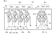
- FIG. 12 shows a third example of the antenna arrangement in which the first antenna and the second antenna are not specified as the transmitting antenna Tx and the receiving antenna Rx.
- the first antennas At1a and At1b of the first antenna group Gr1 are arranged at an antenna interval D1 having a predetermined distance d.
- the four second antennas At2a, At2b, At2c, and At2d, which operate in the opposite direction to the first antenna, are arranged at an antenna distance D2 that is twice the distance d, that is, 2d.
- the antenna spacing D1 is an antenna spacing between adjacent first antennas.
- the antenna spacing D2 is the antenna spacing between adjacent second antennas.
- the radar device 1 provided with the antenna of the third example of the antenna arrangement has the configuration shown in FIG. 1 when the first antenna is the transmitting antenna Tx, and is an antenna when the first antenna is the receiving antenna Rx. It has the same configuration as the radar device 1 equipped with the antenna of the second example of the arrangement.
- the virtual receiving antenna group 50 formed by the first antenna At1 and the second antenna At2 in the third example of the antenna arrangement is shown in FIGS. 13 and 14.
- the virtual receiving antenna group 50 shown in FIG. 13 is the case where the first antenna At1 is the transmitting antenna Tx
- the virtual receiving antenna group 50 shown in FIG. 14 is the case where the first antenna At1 is the receiving antenna Rx.
- the modulation pattern 61 is a pattern that repeats in the order of Tx1 and Tx2.
- the modulation pattern 61 is a pattern that repeats in the order of Tx1, Tx2, Tx3, and Tx4.
- the first antenna At1a includes a plurality of element antennas 19 arranged along the phase center line 31a passing through the phase center C1a.
- the first antenna At1b includes a plurality of element antennas 19 arranged along the phase center line 31b passing through the phase center C1b.
- a plurality of element antennas 19 of the first antenna At1 are arranged along the phase center line passing through the phase center.
- the second antennas At2a, At2b, At2c, and At2d also have a plurality of element antennas 19 arranged along the phase center line passing through the phase center.
- the second antenna At2a includes a plurality of element antennas 19 arranged along the phase center line 32a passing through the phase center C2a, and the second antenna At2b is arranged along the phase center line 32b passing through the phase center C2b.
- the plurality of element antennas 19 are provided.
- the second antenna At2c includes a plurality of element antennas 19 arranged along the phase center line 32c passing through the phase center C2c, and the second antenna At2d is arranged along the phase center line 32d passing through the phase center C2d.
- the plurality of element antennas 19 are provided.
- the extension direction of each phase center line of the first antenna At1 and the second antenna At2 is also the extension direction of the plurality of element antennas 19.
- the first antennas At1 are arranged side by side on the surface of the substrate 23 so as to be parallel to each other, that is, the phase center lines are parallel to each other.
- the arrangement direction of the first antenna At1 is the first arrangement direction dr1.
- the first arrangement direction dr1 is a direction perpendicular to the phase center lines 31a and 31b.
- the antenna distance D1 between the two first antennas At1a and the first antenna At1b, that is, the distance between the phase center line 31a and the phase center line 31b is equal to the distance d.
- the second antennas At2 are arranged side by side on the surface of the substrate 23 so as to be parallel to each other, that is, the phase center lines are parallel to each other.
- the arrangement direction of the second antenna At2 is the second arrangement direction dr2.
- the second arrangement direction dr2 is a direction perpendicular to the phase center lines 32a to 32c.
- the first arrangement direction dr1 and the second arrangement direction dr2 are parallel to each other.
- FIG. 12 shows an example in which the phase centers C1a and C1b of the first antenna At1 and the phase centers C2a, C2b, C2c and C2d of the second antenna At2 are arranged on the same axis.
- the first antennas At1a and At2a are arranged in order toward the positive side of the first arrangement direction dr1, and the second antennas At2a, At2b, At2c and At2d are arranged in order toward the positive side of the second arrangement direction dr2. There is.
- the virtual receiving antennas VR1 to VR8 are arranged in the order of VR1, VR5, VR2, VR6, VR3, VR7, VR4, and VR8 toward the positive side of the third arrangement direction dr3, respectively.
- VR1, VR2, VR3, and VR4 shown by solid circles transmit with the first antenna At1a as a transmitting antenna, and the second antennas At2a, At2b, At2c, At2d as receiving antennas.
- VR5, VR6, VR7, VR8 shown by a broken line circle transmit with the first antenna At1b as a transmitting antenna, and the second antenna At2a, At2b as a receiving antenna.
- At2c, At2d is a virtual receiving antenna formed by signals received.
- the virtual receiving antennas VR1 to VR8 are arranged in the order of VR1, VR2, VR3, VR4, VR5, VR6, VR7, and VR8 toward the positive side of the third arrangement direction dr3, respectively.
- the signals VR1, VR3, VR5, and VR8 shown by the solid circles are transmitted by the second antennas At2a to At2d as the transmitting antenna and received by the first antenna At1a as the receiving antenna.
- a virtual receiving antenna formed by, in which VR2, VR4, VR6, and VR8 indicated by broken circles transmit signals through the second antennas At2a to At2d as transmitting antennas and are received by the first antenna At1b as a receiving antenna. It is a virtual receiving antenna formed by.
- the radar device 1 of the first embodiment provided with the first antenna At1 and the second antenna At2 arranged in the third example of the antenna arrangement is the radar device 1 of the first embodiment provided with the antenna of the third example of the antenna arrangement. It is 1.
- the radar device 1 of the first embodiment including the antenna of the third example of the antenna arrangement has a plurality of transmitting antennas or a first antenna At1 which is a receiving antenna arranged at an antenna interval D1 of a predetermined distance d.
- the first antenna group Gr1 and the second antenna group Gr2 having an arbitrary number of two or more first antennas At1 and a second antenna At2 operating in the opposite direction are provided, and the second antennas having a wide interval are interpolated by the first antenna At1.
- the virtual receiving antenna group 50 having a plurality of virtual receiving antennas VR configured to do so is provided, antennas having three or more channels cannot be physically arranged at equal intervals of a distance d by the feeding circuit 25. Even so, the side lobes can be reduced and erroneous detection can be suppressed.
- the first antenna At1 is the transmitting antenna Tx having a transmitting function
- the second antenna At2 is the receiving antenna Rx having a receiving function. It is preferable to apply the first example of the antenna arrangement, which is the arrangement. The reason is as follows.
- the second antenna At2 is the transmitting antenna Tx, that is, in the second example of the antenna arrangement, the number of transmitting antennas Tx is larger than the number of receiving antennas Rx.
- the larger the number of transmitting antennas Tx the larger the scale of the transmitting circuit 12 in the radar device 1.
- the number of channels of the first antenna At1 that is, the number of antennas is limited by 2
- the number of channels of the second antenna At2 that is, the number of antennas is larger than that of the first antenna At1
- the first antenna At1 is used as the transmitting antenna Tx to generate heat. It is possible to realize a radar device 1 with a small amount.
- the feeding circuit 25 is not limited to this.
- 15 to 20 show the antennas of the first to sixth examples.
- the feeding circuit 25a in the first example of the antenna shown in FIG. 15 is a feeding circuit of a parallel feeding system.
- the first example of the antenna shown in FIG. 15 includes four element antennas 19 and a feeding circuit 25a.
- the second example of the antenna shown in FIG. 16 includes four element antennas 19 and the feeding circuit 25b, and the third example of the antenna shown in FIG. 17 includes four element antennas 19 and the feeding circuit 25c. There is.
- the 18 includes eight element antennas 19 and a feeding circuit 25d.
- the fifth example of the antenna shown in FIG. 19 includes four element antennas 19 and a feeding circuit 25e.
- the sixth example of the antenna shown in FIG. 20 includes four element antennas 19 and a feeding circuit 25f.
- 25 is used as a whole, and 25a, 25b, 25c, 25d, 25e, and 25f are used for distinction.
- the connection portion of the element antenna 19 is the first arrangement direction dr1 of the first antenna At1 of the first antenna group Gr1 or the second antenna At2 of the second antenna group Gr2. This is an example of being parallel to the second arrangement direction dr2 of. Since the extending direction of the plurality of element antennas 19 is perpendicular to the first arrangement direction dr1 or the second arrangement direction dr2, the feeding circuit 25a of the first example of the antenna shown in FIG. 15 has a plurality of connection portions with the element antenna 19. It can also be said that the element antenna 19 is perpendicular to the extending direction.
- connection portion with the element antenna 19 is in the extending direction of the plurality of element antennas 19.
- the feeding circuit 25c of the third example of the antenna shown in FIG. 17 is an example in which the connection portion with the element antenna 19 is slanted with respect to the extending direction of the plurality of element antennas 19.
- the second example and the third example of the antenna are parallel feeding methods formed so that the wiring lengths to the respective element antennas 19 are equal.
- the radar device 1 of the first embodiment including the second example and the third example of the antenna even if the receiving antennas of three or more channels or the receiving antennas cannot be physically arranged at a predetermined distance d interval, the receiving antennas or the receiving antennas cannot be arranged. Side lobes can be reduced and false positives can be suppressed.
- the shape of the element antenna 19 is expressed by a quadrangle, the shape of the element antenna 19 may be any shape.
- the number of rows of antennas constituting one channel may be increased to two or more rows.
- FIG. 18 shows an example in which two sets having eight element antennas 19 and a feeding circuit 25d and having four element antennas 19 are extended in a direction perpendicular to the first arrangement direction dr1 or the second arrangement direction dr2. Indicated.
- the radar device 1 of the first embodiment is an example in which two first antennas At1 arranged at intervals of a predetermined distance d form a set, and this set of first antennas At1 is provided. ..
- the radar device 1 of the second to sixth embodiments to be described later, and the radar device 1 provided with the antennas arranged in the seventh example of the antenna arrangement shown in FIG. 25, are the first antennas arranged at intervals of a predetermined distance d. This is an example in which two At1s form a set, and a plurality of sets of the first antenna At1 are provided.
- the transmitting antenna Tx or the receiving antenna Rx is an example in which three or more channels are not physically arranged at a predetermined distance d. be.
- a complete tournament type that is, a parallel feeding type feeding circuit such as the feeding circuits 25a, 25b, 25c.
- the feeding circuit 25e of the fifth example of the antenna shown in FIGS. 19 and 20 and the feeding circuit 25f of the sixth example of the antenna may be used.
- the desired antenna characteristics are realized in the required specific band. If possible, even if receiving antennas or receiving antennas of 3 or more channels cannot be physically arranged at predetermined distance intervals, side lobes are reduced and false detection is suppressed while ensuring the required specific bandwidth. be able to.
- the desired antenna characteristic is the antenna characteristic set by the design, that is, the designed antenna characteristic.
- the first arrangement direction dr1, the second arrangement direction dr2, and the third arrangement direction dr3 indicate the arrangement directions of adjacent antennas, not the directions between the phase centers.
- a part of the plurality of antennas may be displaced in the extending direction of the element antenna 19.
- FIG. 21 shows an example in which the receiving antennas Rx1 and Rx2 in the first antenna group Gr1 are deviated from each other in the extending direction of the element antenna 19 or the extending direction of the phase center line.
- the radar device 1 provided with the antenna of the fourth example of the antenna arrangement shown in FIG. 21 has the same configuration as the radar device 1 provided with the antenna of the second example of the antenna arrangement except for the antenna arrangement.
- FIG. 22 shows a virtual receiving antenna group 50 formed by the transmitting antenna Tx and the receiving antenna Rx in the fourth example of the antenna arrangement shown in FIG. 21.
- the fourth example of the antenna arrangement is different from the second example of the antenna arrangement shown in FIG. 11 in that the receiving antennas Rx1 and Rx2 in the first antenna group Gr1 are displaced from each other in the extending direction of the element antenna 19 or the extending direction of the phase center line. It is different in that it is. Therefore, in the virtual receiving antenna group 50 formed by the fourth example of the antenna arrangement, the virtual receiving antennas VR2, VR4, VR6, and VR8 shown by the broken line circles are displaced in the extending direction of the phase center line of the antennas.
- the direction from the upper side to the lower side of the paper surface of the phase center lines 27a and 27b in FIG. 21 is defined as the positive side of the extension direction of the phase center line. Since the receiving antenna Rx2 is deviated from the receiving antenna Rx1 to the positive side in the extending direction of the phase center line, the virtual receiving antenna group 50 also has the virtual receiving antennas VR2 and VR4 formed by the signals received by the receiving antenna Rx2. , VR6, VR8 are shifted to the positive side in the extending direction of the phase center line from the virtual receiving antennas VR1, VR3, VR5, VR7 formed by the signal received by the receiving antenna Rx1.
- the radar device 1 of the first embodiment including the transmitting antenna Tx and the receiving antenna Rx arranged in the fourth example of the antenna arrangement shown in FIG. 21 is the first embodiment including the antenna of the fourth example of the antenna arrangement.
- the radar device 1 of the first embodiment including the antenna of the fourth example of the antenna arrangement has a plurality of first antennas arranged at an antenna interval D1 of a predetermined distance d, that is, a first antenna group having a receiving antenna Rx. It is provided with Gr1 and a second antenna group Gr2 having an arbitrary number of two or more first antennas and a second antenna of reverse operation, that is, a transmitting antenna Tx, and the first is between each second antenna having a distance wider than the distance d.
- the feeding circuit 25 physically arranges the virtual receiving antennas at equal intervals of the distance d. Even in cases where antennas with three or more channels cannot be arranged, side lobes can be reduced and erroneous detection can be suppressed.
- the radar device 1 may include an antenna other than the first antenna group Gr1 and the second antenna group Gr2.
- the first antenna group Gr1 and the second antenna group Gr2 of the second example of the antenna arrangement shown in FIG. 10 and the transmitting antenna FTx, the receiving antenna FRx1 and the FRx2 are arranged.
- the antenna for detecting a long distance does not necessarily have to be a wide band antenna. Therefore, for long distances, the conventional transmitting antenna FTx, receiving antenna FRx1 and FRx2, which are antennas having a narrow band, can be used.
- the radar device 1 provided with the antenna of the fifth example of the antenna arrangement shown in FIG.
- the 23 is a transmission circuit for the transmitting antenna FTx, the receiving antennas FRx1 and FRx2 in the radar device 1 having the antenna of the second example of the antenna arrangement. , It is configured to have a receiving circuit.
- the target object 33 can be detected. Since the radar device 1 provided with the antenna of the fifth example of the antenna arrangement includes the radar device 1 of the first embodiment provided with the antenna of the second example of the antenna arrangement, the antenna of the second example of the antenna arrangement is used. It has the same effect as the radar device 1 of the first embodiment provided.
- the sixth example of the antenna arrangement shown in FIG. 24 is an example in which the first antenna group Gr1 and the second antenna group Gr2 and the transmitting antenna Tx5 of the second example of the antenna arrangement shown in FIG. 10 are arranged.
- the receiving antennas Rx1 and Rx2 of the first antenna group Gr1 are arranged on the surface of the substrate 23b, and the transmitting antennas Tx1 to Tx4 and the transmitting antenna Tx5 of the second antenna group Gr2 are arranged on the surface of the substrate 23a. showed that.
- the transmission changeover switch 124 is changed from the radar device 1 provided with the antenna of the second example of the antenna arrangement with the addition of the transmitting antenna Tx5.
- the transmitting antennas Tx1, Tx2, Tx3, Tx4, and Tx5 are configured to be switched.
- the transmitting antenna Tx5 includes a plurality of element antennas 19 arranged along the phase center line 28e passing through the phase center Ct5.
- FIG. 24 shows an example in which the transmitting antenna spacing Dtxa between the transmitting antenna Tx5 and the transmitting antenna Tx4 of the adjacent second antenna group Gr2 is longer than the transmitting antenna spacing Dtx. Since the radar device 1 provided with the antenna of the sixth example of the antenna arrangement includes the radar device 1 of the first embodiment provided with the antenna of the second example of the antenna arrangement, the antenna of the second example of the antenna arrangement is used. It has the same effect as the radar device 1 of the first embodiment provided.
- a plurality of sets of antennas of the first antenna group Gr1 and the second antenna group Gr2 may be arranged in the extending direction of the phase center line.
- the seventh example of the antenna arrangement shown in FIG. 25 corresponds to an antenna arrangement including two sets of the first antenna group Gr1 and the second antenna group Gr2 of the first example of the antenna arrangement shown in FIG.
- the first antenna group Gr1 includes four transmitting antennas Tx1, Tx2, Tx3, Tx4, and the second antenna group Gr2 has eight receiving antennas Rx1, Rx2, Rx3, Rx4, Rx5, Rx6, Rx7, It is equipped with Rx8.
- the transmitting antenna Tx includes a set of antennas having an antenna distance of d or less, and the receiving antenna Rx does not include a set of antennas having an antenna spacing of d or less.
- the transmitting antennas Tx1 and Tx2 form the first antenna set 22a
- the transmitting antennas Tx3 and Tx4 form the first antenna set 22b.
- the receiving antennas Rx1 to Rx4 form a second antenna set 24a
- the receiving antennas Rx5 to Rx8 form a second antenna set 24b.
- the first antenna set 22b and the second antenna set 24b are the first examples of the antenna arrangement shown in FIG.
- the first antenna set 22a and the second antenna set 24a have an antenna arrangement in which the transmitting antenna Tx and the receiving antenna Rx in the first example of the antenna arrangement shown in FIG. 4 are displaced in the extending direction of the phase center line.
- FIG. 25 there is one first antenna set arranged in the first arrangement direction dr1 of the first antenna group Gr1, and the first antenna set arranged in the second arrangement direction dr2 of the second antenna group Gr2.
- An example is shown in which is one.
- the first antenna group Gr1 has the same configuration as the A group having a plurality of first antennas At1 arranged in the first arrangement direction dr1 and the A group, and is in the first arrangement direction dr1.
- the group B is arranged in the fourth arrangement direction dr4, which is the vertical direction.
- the group A is the first antenna set 22a
- the group B is the first antenna set 22b.
- the second antenna group Gr2 has the same configuration as the C group having a plurality of second antennas At2 arranged in the second arrangement direction dr2 and the C group, and has a direction perpendicular to the second arrangement direction dr2.
- the group D arranged in the fifth arrangement direction dr5 is provided.
- the group C is the second antenna set 24a
- the group D is the second antenna set 24b.
- the transmission changeover switch 124 of the transmission circuit 12 is configured to switch the transmission antennas Tx1, Tx2, Tx3, and Tx4.
- the receiving circuit 13 includes eight mixers 131, eight filter circuits 141, and eight analog-to-digital converters 151 corresponding to the receiving antennas Rx1, Rx2, Rx3, Rx4, Rx5, Rx6, Rx7, and Rx8. It is configured to have.
- the radar device 1 provided with the antenna of the seventh example of the antenna arrangement transmits a transmission signal having a modulation pattern 61 that repeats in the order of Tx1, Tx2, Tx3, and Tx4.
- the transmitting antennas Tx1 and Tx3 include a plurality of element antennas 19 arranged along the phase center line 28a
- the transmitting antennas Tx2 and Tx4 include a plurality of element antennas 19 arranged along the phase center line 28b.
- the receiving antennas Rx1 and Rx5 include a plurality of element antennas 19 arranged along the phase center line 27a
- the receiving antennas Rx2 and Rx6 include a plurality of element antennas 19 arranged along the phase center line 27b.
- the receiving antennas Rx3 and Rx7 include a plurality of element antennas 19 arranged along the phase center line 27c
- the receiving antennas Rx4 and Rx8 include a plurality of element antennas 19 arranged along the phase center line 27d.
- the transmitting antennas Tx1 and Tx3 and the transmitting antennas Tx2 and Tx4 are arranged side by side on the surface of the substrate 23 so as to be parallel to each other, that is, the phase center lines are parallel to each other.
- the transmitting antennas Tx1 and Tx2 in the first antenna set 22a are arranged in the first arrangement direction dr1, and the transmitting antennas Tx3 and Tx4 in the first antenna set 22b are arranged in the first arrangement direction dr1.
- the receiving antennas Rx1 to Rx4 in the second antenna set 24a are arranged in the second arrangement direction dr2, and the receiving antennas Rx5 to Rx8 in the second antenna set 24b are arranged in the second arrangement direction dr2.
- FIG. 25 shows an example in which the phase centers of the receiving antennas Rx5 to Rx8 in the second antenna set 24b and the phase centers of the first antenna set 22b are arranged on the broken line 29a having the same axis.
- the first antenna set 22a and the first antenna set 22b are arranged in order toward the positive side of the fourth arrangement direction dr4 perpendicular to the first arrangement direction dr1.
- the second antenna set 24a and the second antenna set 24b are arranged in order toward the positive side of the fifth arrangement direction dr5 perpendicular to the second arrangement direction dr2.
- the phase centers of the transmitting antennas Tx1 and Tx2 in the first antenna set 22a are arranged on the broken line 29b which is the same axis.
- the phase centers of the receiving antennas Rx1 to Rx4 of the second antenna set 24a are arranged on the broken line 29c which is the same axis.
- the dashed lines 29a, 29b, and 29c are parallel to each other.
- the distance from the phase center line 28b is equal to the distance d.
- the distance between the adjacent phase center lines of the center lines 27a to 27d is twice the distance d, that is, 2d.
- the transmitting antenna set spacing Dtxsv which is the first antenna set spacing between the first antenna set 22a and the first antenna set 22b, is the spacing between the broken line 29b and the broken line 29a.
- the receiving antenna set spacing Drxsv which is the second antenna set spacing between the second antenna set 24a and the second antenna set 24b, is the spacing between the broken line 29c and the broken line 29a.
- FIG. 26 shows a virtual receiving antenna group 50 formed by the transmitting antenna Tx and the receiving antenna Rx in the seventh example of the antenna arrangement of FIG. 25.
- 32 virtual receiving antennas VR1 to VR32 are formed by four transmitting antennas Tx1 to Tx4 and eight receiving antennas Rx1 to Rx8.
- VR1, VR2, VR3, VR4, VR5, VR6, VR7, VR8 shown by the white solid line circles are virtual receiving antennas formed by signals transmitted by the transmitting antenna Tx1 and received by the receiving antennas Rx1 to Rx8, and are white.
- a set of eight virtual receiving antennas VR arranged in the third arrangement direction dr3 parallel to the first arrangement direction dr1 and the second arrangement direction dr2 is arranged in the third arrangement direction dr3.
- Four sets are arranged in the sixth arrangement direction dr6 perpendicular to.
- the sixth arrangement direction dr6 is a direction parallel to the fourth arrangement direction dr4 and the fifth arrangement direction dr5.
- the first set, the second set, the third set, and the fourth set are made in order toward the positive side of the sixth arrangement direction dr6.
- the adjacent virtual receiving antenna intervals Dvr in the first set of virtual receiving antennas VR1, VR9, VR2, VR10, VR3, VR11, VR4, and VR12 are configured to be evenly spaced at a distance d.
- the virtual receiving antennas VR1 to VR4 are the first set of virtual receiving antennas formed by the signals transmitted by the transmitting antenna Tx1 and received by the receiving antennas Rx1 to Rx4, and the virtual receiving antennas VR9 to VR12 are transmitted by the transmitting antenna Tx2. This is the first set of virtual receiving antennas formed by the signals received by the receiving antennas Rx1 to Rx4.
- the second set of virtual receiving antennas VR5, VR13, VR6, VR14, VR7, VR15, VR8, and VR16 are configured so that the adjacent virtual receiving antenna intervals Dvr are evenly spaced at a distance d.
- the virtual receiving antennas VR5 to VR8 are the second set of virtual receiving antennas formed by the signals transmitted by the transmitting antenna Tx1 and received by the receiving antennas Rx5 to Rx8, and the virtual receiving antennas VR13 to VR16 are transmitted by the transmitting antenna Tx2. This is the second set of virtual receiving antennas formed by the signals received by the receiving antennas Rx5 to Rx8.
- the adjacent virtual receiving antenna intervals Dvr in the third set of virtual receiving antennas VR17, VR25, VR18, VR26, VR19, VR27, VR20, and VR28 are configured to be evenly spaced at a distance d.
- the virtual receiving antennas VR17 to VR20 are the third set of virtual receiving antennas formed by the signals transmitted by the transmitting antenna Tx3 and received by the receiving antennas Rx1 to Rx4, and the virtual receiving antennas VR25 to VR28 transmit by the transmitting antenna Tx4. This is a third set of virtual receiving antennas formed by signals received by the receiving antennas Rx1 to Rx4.
- the adjacent virtual receiving antenna intervals Dvr in the fourth set of virtual receiving antennas VR21, VR29, VR22, VR30, VR23, VR31, VR24, and VR32 are configured to be evenly spaced at a distance d.
- the virtual receiving antennas VR21 to VR24 are the fourth set of virtual receiving antennas formed by the signals transmitted by the transmitting antenna Tx3 and received by the receiving antennas Rx5 to Rx8, and the virtual receiving antennas VR29 to VR32 transmit by the transmitting antenna Tx4. This is a fourth set of virtual receiving antennas formed by signals received by the receiving antennas Rx5 to Rx8.
- the distance between the first set of virtual receiving antennas and the second set of virtual receiving antennas in the sixth arrangement direction dr6 is the receiving antenna set spacing Drxsv, and the distance between the third set of virtual receiving antennas and the fourth set of virtual receiving antennas.
- the interval in the sixth arrangement direction dr6 is the receiving antenna set interval Drxsv.
- the distance between the first set of virtual receiving antennas and the third set of virtual receiving antennas in the sixth arrangement direction dr6 is the transmission antenna set distance Dtxsv. Since the radar device 1 provided with the antenna of the seventh example of the antenna arrangement corresponds to the radar device 1 of the first embodiment provided with two sets of the antennas of the first example of the antenna arrangement, the antenna of the first example of the antenna arrangement is provided.
- the radar device 1 provided with the antenna of the seventh example of the antenna arrangement determines the distance, relative velocity, and angle of the target object 33 in two dimensions of the third arrangement direction dr3 and the sixth arrangement direction dr6 perpendicular to the third arrangement direction dr3. Can be measured.
- the first antenna At1 having three or more channels cannot be physically arranged at a predetermined distance d
- the first antenna having two channels physically at a distance d.
- a plurality of virtual receiving antennas VR formed by transmission / reception of the first antenna At1 and the second antenna At2 can be arranged at equal intervals of the distance d, side lobes are reduced and an error is made. Detection can be suppressed.
- the radar device 1 of the first embodiment receives the plurality of transmitting antennas Tx that radiate the transmitted signal toward the target object 33 and the reflected signal that the transmitted signal is reflected by the target object 33. It includes a plurality of receiving antennas Rx that are output as reception signals, and a processing unit 11 that processes reception signals output from each of the plurality of reception antennas Rx.
- the antenna distance between adjacent antennas which is determined based on the viewing range required for the radar device 1, is set as the basic distance (distance d), and either a plurality of transmitting antennas Tx or a plurality of receiving antennas Rx are provided.
- the antenna group having a first antenna set having a plurality of first antennas At1 which is an antenna group and the antenna distance D1 between adjacent antennas is a basic distance (distance d) is defined as the first antenna group Gr1. It is an antenna group having a plurality of other antennas different from the first antenna At1 of the group Gr1, and has a plurality of second antennas At2 in which the antenna distance D2 between adjacent antennas is twice the basic distance (distance d).
- the antenna group provided with the second antenna set is referred to as the second antenna group Gr2.
- the first antenna At1 and the second antenna At2 include a plurality of element antennas 19 and a feeding circuit 25 for supplying electric power to the element antennas 19.
- the plurality of first antennas At1 are arranged side by side in the first arrangement direction dr1 perpendicular to the transmission direction of the transmission signal, and each feeding circuit 25 is provided on the positive side or the negative side of the first arrangement direction dr1. ..
- the plurality of second antennas At2 are arranged side by side in the second arrangement direction dr2 perpendicular to the transmission direction of the transmission signal and parallel to the first arrangement direction dr1, and the feeding circuit 25 is arranged on the positive side or the negative side of the second arrangement direction dr2. Have on the side.
- the feeding circuit 25 is not arranged between the adjacent antennas in the first antenna set.
- the virtual receiving antenna group 50 composed of a plurality of virtual receiving antennas VR formed by the plurality of first antennas At1 of the first antenna group Gr1 and the plurality of second antennas At2 of the second antenna group Gr2 transmits a transmission signal. They are arranged side by side in the third arrangement direction dr3 which is perpendicular to the direction and parallel to the first arrangement direction dr1 and the second arrangement direction dr2, and the distance between adjacent virtual receiving antennas VR in the third arrangement direction dr3 (virtual receiving antenna distance Dvr). ) Is the basic distance (distance d).
- the radar device 1 of the first embodiment has a first antenna set having a plurality of first antennas At1 in which the antenna distance D1 between the antennas adjacent to the first antenna group Gr1 is the basic distance (distance d).
- the second antenna group Gr2 comprises a second antenna set having a plurality of second antennas At2 in which the antenna distance D2 between adjacent antennas is twice the basic distance (distance d), and the plurality of first antennas At1 and Since the interval (virtual receiving antenna interval Dvr) of the adjacent virtual receiving antenna VRs of the plurality of virtual receiving antennas VR formed by the transmission / reception of the plurality of second antennas At2 is the basic distance (distance d), a predetermined distance is used. Even when the first antenna At1 which is the receiving antenna Rx or the transmitting antenna Tx of three or more channels cannot be physically arranged at the interval of d, the side lobe can be reduced and erroneous detection can be suppressed.
- Embodiment 2 is a diagram showing an antenna arrangement of the radar device according to the second embodiment
- FIG. 28 is a diagram showing a virtual receiving antenna group corresponding to the antenna arrangement of FIG. 27.
- the first antenna group Gr1 has two antenna groups in the first arrangement direction dr1 and has only one antenna set.
- the radar device 1 of the second embodiment is an example in which the first antenna group Gr1 is provided with two antenna sets in the first arrangement direction dr1. A part different from the radar device 1 of the first embodiment will be mainly described.
- the radar device 1 of the second embodiment including the antenna of the antenna arrangement of FIG.
- the radar device 1 provided with the antenna of the antenna arrangement of FIG. 27 transmits a transmission signal having a modulation pattern 61 that repeats in the order of Tx1 and Tx2.
- the receiving antenna Rx is the antenna of the first antenna group Gr1, that is, the first antenna At1
- the transmitting antenna Tx is the antenna of the second antenna group Gr2, that is, the second antenna At2.
- the receiving antennas Rx1, Rx2, RX3, and RX4 are arranged in order toward the positive side of the first arrangement direction dr1
- the transmitting antennas Tx1 and Tx2 are arranged in order toward the positive side of the second arrangement direction dr2.
- the receiving antenna spacing Drx that is, the spacing between the phase center line 27a and the phase center line 27b is equal to the distance d.
- the receiving antenna spacing Drx that is, the spacing between the phase center line 27c and the phase center line 27d is equal to the distance d.
- the receiving antenna interval Drx is the antenna interval D1 (see FIG. 12) at the distance d in the first antenna At1.
- the receiving antennas Rx1 and Rx2 form the first antenna set 22a
- the receiving antennas Rx3 and Rx4 form the first antenna set 22b.
- the distance between the first antenna set 22a and the first antenna set 22b is Dg1s, that is, the distance between the phase center line 27a and the phase center line 27c is four times the distance d, that is, 4d.
- the first antenna set spacing Dg1s may be the spacing between the phase center line 27b and the phase center line 27d.
- the first antenna set interval Dg1s is the interval between adjacent first antenna sets.
- the distance between the transmitting antenna spacing Dtx, that is, the phase center line 28a and the phase center line 28b is twice the distance d, that is, 2d.
- the transmitting antenna spacing Dtx is an antenna spacing D2 (see FIG. 12) that is twice the distance d in the second antenna At2.
- the feeding circuit 25 of the transmitting antenna Tx and the receiving antenna Rx shows a feeding circuit of a parallel feeding system formed so that the wiring lengths to the respective element antennas 19 are equal.
- the transmitting antenna Tx is the second antenna At2 of the second antenna group Gr2
- the feeding circuit 25 is arranged in a region adjacent to the other receiving antennas and the element antennas 19 are arranged so as not to face each other. ..
- the receiving antenna Rx is the first antenna At1 of the first antenna group Gr1
- the receiving antennas Rx1 and Rx2 of the first antenna set 22a have the element antenna 19 so that the feeding circuit 25 is not arranged in the region adjacent to the other receiving antennas.
- the receiving antennas Rx3 and Rx4 of the first antenna set 22b are arranged so that the element antennas 19 face each other so that the feeding circuit 25 is not arranged in the region adjacent to the other receiving antennas.
- FIG. 28 shows a virtual receiving antenna group 50 formed by the transmitting antenna Tx and the receiving antenna Rx in the antenna arrangement of FIG. 27.
- the virtual receiving antenna group 50 includes a plurality of virtual receiving antennas.
- the virtual receiving antenna spacing Dvr which is the spacing between adjacent virtual receiving antenna VRs in the eight virtual receiving antenna VRs, is configured to be evenly spaced at a distance d.
- Each virtual receiving antenna VR of the virtual receiving antenna group 50 is arranged in the third arrangement direction dr3 at a distance d at equal intervals.
- the third arrangement direction dr3 is a direction parallel to the first arrangement direction dr1 and the second arrangement direction dr2.
- the virtual receiving antennas VR1 to VR8 are arranged in the order of VR1, VR2, VR5, VR6, VR3, VR4, VR7, and VR8 toward the positive side of the third arrangement direction dr3, respectively.
- VR1, VR2, VR3, and VR4 shown by solid circles are virtual receiving antennas formed by signals transmitted by the transmitting antenna Tx1 and received by the receiving antennas Rx1 to Rx4, and are broken lines.
- VR5, VR6, VR7, and VR8 shown by circles are virtual receiving antennas formed by signals transmitted by the transmitting antenna Tx2 and received by the receiving antennas Rx1 to Rx4.
- the virtual receiving antennas VR1 and VR2 are virtual receiving antennas formed by the signals received by the receiving antennas Rx1 and Rx2 of the first antenna set 22a, and the virtual receiving antennas VR3 and VR4 are the receiving antennas Rx3 and Rx4 of the first antenna set 22b. It is a virtual receiving antenna formed by the signal received in. Therefore, the distance between the virtual receiving antenna VR1 by the receiving antenna Rx1 of the first antenna set 22a and the virtual receiving antenna VR3 by the receiving antenna Rx3 of the first antenna set 22b is 4d, which is the first antenna set spacing Dg1s. There is.
- the virtual receiving antennas VR1 and VR3 are virtual receiving antennas by the receiving antennas Rx1 and Rx3 on the negative side of the third arrangement direction dr3 in the first antenna set 22a and 22b.
- the distance between the virtual receiving antennas VR2 and VR4 is also 4d, which is the first antenna set spacing Dg1s.
- VR5, VR6, VR7, and VR8 shown by the broken line circles are also the same as VR1, VR2, VR3, and VR4 shown by the solid line circles, the virtual receiving antenna VR5 by the receiving antenna Rx1 of the first antenna set 22a and the first antenna set 22b.
- the distance between the receiving antenna Rx3 and the virtual receiving antenna VR7 is 4d, which is the first antenna set distance Dg1s. That is, the receiving antennas Rx1 on the negative side of the third arrangement direction dr3 in the first antenna sets 22a and 22b, and the virtual receiving antennas VR5 and VR7 by Rx3 have a first antenna set spacing Dg1s in which the spacing between them is 4d.
- the distance between them is 4d, which is the first antenna set spacing Dg1s.
- Ng2 is the number of second antennas, that is, the number of second antennas.
- the number of second antennas Ng2 is 2
- the second antenna At2 of the second antenna group Gr2 is the transmitting antenna Tx, and between the adjacent second antennas At2 of the second antenna group Gr2.
- the antenna spacing D2 is a transmitting antenna spacing Dtx that is twice the distance d.
- the first antenna set interval Dg1s is 2 ⁇ D2, which is 4d.
- the plurality of first antennas At1 arranged at the antenna spacing D1 having a predetermined distance d may be the transmitting antenna Tx or the receiving antenna Rx.
- the second antenna At2 is an antenna that operates in the opposite direction to the first antenna At1.
- the first antenna At1 was four and the second antenna At2 was two.
- the antenna in the radar device 1 of the second embodiment is not limited to this. It is sufficient that the first antenna At1 is an even number of 4 or more, the first antenna set is provided by 2 or more, and the second antenna At2 is 2 or more.
- the number of the first antennas At1 included in the first antenna group Gr1 is an even number of 4 or more, and the number of the second antennas At2 included in the second antenna group Gr2 is 2 or more.
- the transmitting circuit 12 and the receiving circuit 13 correspond to the number of transmitting antennas Tx which is one of the first antenna At1 and the second antenna At2, and the number of receiving antennas Rx which is the other of the first antenna At1 and the second antenna At2. It has a structure that is similar to that of the antenna.
- the first antenna set spacing Dg1s which is an adjacent spacing in the first antenna set having two first antennas At1 arranged at a predetermined distance d spacing, is the first.
- the first antenna At1 is arranged so as to be a value obtained by multiplying the number Ng2 of the second antenna, which is the number of the two antennas At2, and the antenna distance D2, which is the distance between the adjacent second antennas At2 in the second antenna group Gr2. ing.
- the first antenna At1 having three or more channels cannot be physically arranged at a predetermined distance d, but the first antenna At1 and the second antenna At2 can transmit and receive. Since the plurality of virtual receiving antennas VR formed can be arranged at equal intervals of the distance d, side lobes can be reduced and erroneous detection can be suppressed.
- the radar device 1 of the first embodiment including the first antenna At1 and the second antenna At2 arranged in the first to sixth examples of the antenna arrangement is suitable when the first antenna At1 has two channels. ..
- the radar device 1 of the second embodiment is suitable when the first antenna At1 is an even number of two or more channels.
- a plurality of antennas of the first antenna group Gr1 and the second antenna group Gr2 are set in the extending direction of the phase center line, as in the seventh example of the antenna arrangement shown in FIG. It may be arranged.
- the distance, relative velocity, and angle of the target object 33 can be measured in two dimensions of the third arrangement direction dr3 and the sixth arrangement direction dr6 perpendicular to the third arrangement direction dr3.
- FIG. 29 is a diagram showing an antenna arrangement of the radar device according to the third embodiment
- FIG. 30 is a diagram showing an arrangement of the transmitting antenna of FIG. 29
- FIG. 31 is a diagram showing a virtual receiving antenna group corresponding to the antenna arrangement of FIG. 29.
- the first antenna group Gr1 is provided with two antenna sets in the first arrangement direction dr1.
- the radar device 1 of the third embodiment is an example in which the first antenna group Gr1 is provided with a plurality of antenna sets of two in the first arrangement direction dr1 as in the radar device 1 of the second embodiment.
- This is an example in which the number of the second antenna At2 of the second antenna group Gr2 is a prime number of 2 or more.
- the radar device 1 of the third embodiment provided with the antennas of the antenna arrangements of FIGS. 29 and 30, the first antenna group Gr1 has three antenna sets, and the second antenna group Gr2 has the second antenna At2. It differs from the radar device 1 of the second embodiment, which comprises the antenna of the antenna arrangement of FIG. 27, in that the number of antennas Tx is 3.
- the radar device 1 of the third embodiment provided with the antennas of the antenna arrangements of FIGS. 29 and 30, has three transmitting antennas Tx1, Tx2, Tx3, and six receiving antennas Rx1, Rx2, Rx3. It includes Rx4, Rx5, Rx6, a transmission circuit 12, a reception circuit 13, and a processing unit 11.
- the transmission circuit 12 is configured such that the transmission changeover switch 124 switches between three transmission antennas Tx1, Tx2, and Tx3.
- the receiving circuit 13 has a configuration corresponding to six receiving antennas Rx1 to Rx6.
- the radar device 1 provided with the antennas of the antenna arrangements of FIGS. 29 and 30 transmits a transmission signal having a modulation pattern 61 that repeats in the order of Tx1, Tx2, and Tx3.
- the receiving antenna Rx is the antenna of the first antenna group Gr1, that is, the first antenna At1
- the transmitting antenna Tx is the antenna of the second antenna group Gr2, that is, the second antenna At2.
- the receiving antennas Rx1 to Rx6 are arranged in order toward the positive side of the first arrangement direction dr1
- the transmitting antennas Tx1, Tx2, and Tx3 are arranged in order toward the positive side of the second arrangement direction dr2.
- the receiving antennas Rx1 and Rx2 form the first antenna set 22a
- the receiving antennas Rx3 and Rx4 form the first antenna set 22b
- the receiving antennas Rx5 and Rx6 form the first antenna set 22c.
- the first antenna sets 22a and 22b are as described in the second embodiment.
- the receiving antenna spacing Drx that is, the spacing between the phase center line 27e and the phase center line 27f is equal to the distance d.
- the receiving antenna interval Drx is the antenna interval D1 (see FIG. 12) at the distance d in the first antenna At1.
- the distance between the adjacent first antenna sets of the first antenna sets 22a, 22b, 22c, that is, the first antenna set distance Dg1s is 6 times the distance d, that is, 6d.
- the distance between the first antenna set 22a and the first antenna set 22b is the distance between the phase center line 27a and the phase center line 27c or the distance between the phase center line 27b and the phase center line 27d, and the distance between the first antenna set 22b and the first antenna set 22b.
- the distance from the one antenna set 22c is the distance between the phase center line 27c and the phase center line 27e or the distance between the phase center line 27d and the phase center line 27f.
- the distance between adjacent transmitting antennas Tx is twice the distance d, that is, 2d.
- the distance between the transmitting antenna Tx1 and the transmitting antenna Tx2 is the distance between the phase center line 28a and the phase center line 28b
- the distance between the transmitting antenna Tx2 and the transmitting antenna Tx3 is the distance between the phase center line 28b and the phase center line 28c.
- the transmitting antenna spacing Dtx is an antenna spacing D2 (see FIG. 12) that is twice the distance d in the second antenna At2.
- the feeding circuit 25 of the transmitting antenna Tx and the receiving antenna Rx shows a feeding circuit of a parallel feeding system formed so that the wiring lengths to the respective element antennas 19 are equal. Since the transmitting antenna Tx is the second antenna At2 of the second antenna group Gr2, an example is shown in which the feeding circuit 25 is arranged in a region adjacent to the other transmitting antennas and the element antennas 19 are arranged so as not to face each other. .. Since the receiving antenna Rx is the first antenna At1 of the first antenna group Gr1, the two receiving antennas Rx of the first antenna set 22a, 22b, 22c do not have the feeding circuit 25 arranged in the area adjacent to the other receiving antennas. , The element antennas 19 are arranged so as to face each other.
- FIG. 31 shows a virtual receiving antenna group 50 formed by the transmitting antenna Tx and the receiving antenna Rx in the antenna arrangement of FIGS. 29 and 30.
- the virtual receiving antenna group 50 includes a plurality of virtual receiving antennas. Eighteen virtual receiving antennas VR1 to VR18 are formed by the transmitting antennas Tx1 to Tx3 which are the three second antennas At2 and the receiving antennas Rx1 to Rx6 which are the six first antennas At1.
- the virtual receiving antenna spacing Dvr which is the spacing between adjacent virtual receiving antenna VRs in the 18 virtual receiving antenna VRs, is configured to be evenly spaced at a distance d.
- Each virtual receiving antenna VR of the virtual receiving antenna group 50 is arranged in the third arrangement direction dr3 at a distance d at equal intervals.
- the third arrangement direction dr3 is a direction parallel to the first arrangement direction dr1 and the second arrangement direction dr2.
- the virtual receiving antennas VR1 to VR18 are directed toward the positive side of the third arrangement direction dr3, respectively, VR1, VR2, VR7, VR8, VR13, VR14, VR3, VR4, VR9, VR10, VR15, VR16. , VR5, VR6, VR11, VR12, VR17, VR18 in this order.
- VR1, VR2, VR3, VR4, VR5, and VR6 shown by white solid circles are virtual formed by signals transmitted by the transmitting antenna Tx1 and received by the receiving antennas Rx1 to Rx6.
- It is a receiving antenna, and is a virtual receiving antenna formed by signals transmitted by the transmitting antenna Tx2 and received by the receiving antennas Rx1 to Rx6 by VR7, VR8, VR9, VR10, VR11, and VR12 shown by the white broken line circles.
- the VR13, VR14, VR15, VR16, VR17, and VR18 shown by the pattern solid line circles are virtual receiving antennas formed by signals transmitted by the transmitting antenna Tx3 and received by the receiving antennas Rx1 to Rx6.
- the virtual receiving antennas VR1 and VR2 are virtual receiving antennas formed by the signals received by the receiving antennas Rx1 and Rx2 of the first antenna set 22a, and the virtual receiving antennas VR3 and VR4 are the receiving antennas Rx3 and Rx4 of the first antenna set 22b.
- the virtual receiving antennas VR5 and VR6 are virtual receiving antennas formed by the signals received by the receiving antennas Rx5 and Rx6 of the first antenna set 22c. Therefore, the adjacent intervals in the virtual receiving antennas VR1, VR3, and VR5 by the receiving antenna Rx1 of the first antenna set 22a, the receiving antenna Rx3 of the first antenna set 22b, and the receiving antenna Rx5 of the first antenna set 22c are 6d.
- the first antenna set interval is Dg1s.
- the receiving antennas Rx1, Rx3, and Rx5 are the receiving antennas Rx on the negative side of the third arrangement direction dr3 in the first antenna set 22a, 22b, 22c, but the receiving antennas Rx3 in the first antenna set 22a, 22b, 22c.
- the virtual receiving antennas VR2, VR4, and VR6 by the receiving antennas Rx2, Rx4, and Rx6 which are the receiving antennas Rx on the positive side the distance between them is 6d, which is the first antenna set spacing Dg1s.
- VR7, VR8, VR9, VR10, VR11, and VR12 shown by the white broken line circles also receive the receiving antenna Rx1 and the first antenna set 22b of the first antenna set 22a in the same manner as VR1 to VR6 shown by the white solid line circles.
- the adjacent spacing in the virtual receiving antennas VR7, VR9, and VR11 by the receiving antenna Rx5 of the antenna Rx3 and the first antenna set 22c is 6d, which is the first antenna set spacing Dg1s.
- the distance between the virtual receiving antennas VR8, VR10, and VR12 by the receiving antennas Rx2, Rx4, and Rx6, which are the receiving antennas Rx on the positive side of the third arrangement direction dr3 in the first antenna set 22a, 22b, and 22c, is also 6d.
- the first antenna set interval is Dg1s.
- VR13, VR14, VR15, VR16, VR17, and VR18 shown by the pattern solid line circle are also received by the receiving antenna Rx1 and the first antenna set 22b of the first antenna set 22a in the same manner as VR1 to VR6 shown by the white solid line circle.
- the adjacent spacing in the virtual receiving antennas VR13, VR15, and VR17 by the receiving antenna Rx5 of the antenna Rx3 and the first antenna set 22c is 6d, which is the first antenna set spacing Dg1s.
- the distance between the virtual receiving antennas VR14, VR16, and VR18 by the receiving antennas Rx2, Rx4, and Rx6, which are the receiving antennas Rx on the positive side of the third arrangement direction dr3 in the first antenna set 22a, 22b, and 22c, is also 6d.
- the first antenna set interval is Dg1s.
- the one-antenna set interval Dg1s is determined according to the equation (3).
- the number of second antennas Ng2 is 3
- the second antenna At2 of the second antenna group Gr2 is the transmitting antenna Tx
- the antenna distance D2 between At2 is a transmission antenna distance Dtx that is twice the distance d.
- the first antenna set interval Dg1s is 3 ⁇ D2, which is 6d.
- the plurality of first antennas At1 arranged at the antenna spacing D1 having a predetermined distance d may be the transmitting antenna Tx or the receiving antenna Rx.
- the second antenna At2 is an antenna that operates in the opposite direction to the first antenna At1.
- the first antenna At1 was six and the second antenna At2 was three.
- the antenna in the radar device 1 of the third embodiment is not limited to this. It is sufficient that the number of the first antennas At1 is an even number of 4 or more, the number of the first antenna sets is 2 or more, and the number of the second antennas At2 is 2 or more.
- the number of the first antennas At1 included in the first antenna group Gr1 is an even number of 4 or more, and the number of the second antennas At2 included in the second antenna group Gr2 is 2 or more. It is a prime number, and the transmission circuit 12 and the reception circuit 13 are the number of the transmission antenna Tx which is one of the first antenna At1 and the second antenna At2, and the number of the reception antenna Rx which is the other of the first antenna At1 and the second antenna At2. It has a configuration corresponding to.
- the first antenna set spacing Dg1s which is an adjacent spacing in the first antenna set having two first antennas At1 arranged at a predetermined distance d, is the first.
- the first antenna At1 is arranged so as to be a value obtained by multiplying the number Ng2 of the second antenna, which is the number of the two antennas At2, and the antenna distance D2, which is the distance between the adjacent second antennas At2 in the second antenna group Gr2. ing.
- the first antenna At1 having three or more channels cannot be physically arranged at a predetermined distance d, but the first antenna At1 and the second antenna At2 can transmit and receive. Since the plurality of virtual receiving antennas VR formed can be arranged at equal intervals of the distance d, side lobes can be reduced and erroneous detection can be suppressed.
- the radar device 1 of the third embodiment is suitable for a prime number in which the number of first antennas At1 is an even number of 2 channels or more and the number of second antennas At2 is 2 or more.
- a plurality of virtual receiving antennas VR formed by transmission / reception of the first antenna At1 and the second antenna At2 have a distance d, etc. Can be placed at intervals.
- the second antenna At2 is the transmitting antenna Tx
- a plurality of virtual receiving antennas VR are arranged together for each transmitting antenna Tx in the set of receiving antennas Rx, that is, the first antenna sets 22a, 22b, 22c.
- the receiving antenna VR can be arranged at equal intervals of the distance d.
- a plurality of antennas of the first antenna group Gr1 and the second antenna group Gr2 are set in the extending direction of the phase center line, as in the seventh example of the antenna arrangement shown in FIG. It may be arranged.
- the distance, relative velocity, and angle of the target object 33 can be measured in two dimensions of the third arrangement direction dr3 and the sixth arrangement direction dr6 perpendicular to the third arrangement direction dr3.
- Embodiment 4. 32 is a diagram showing the antenna arrangement of the radar device according to the fourth embodiment, and FIG. 33 is a diagram showing the arrangement of the transmitting antenna of FIG. 32.
- 34 is a diagram showing a virtual receiving antenna group corresponding to the antenna arrangement of FIG. 32
- FIG. 35 is a diagram showing a first virtual receiving antenna group of FIG. 34
- FIG. 36 is a diagram showing a second virtual receiving antenna group of FIG. 34. It is a figure which shows the group.
- a method of expanding the antenna arrangement of the radar device 1 of the second embodiment in the case where the number of the second antennas At2 of the second antenna group Gr2 is a prime number of 2 or more has been described.
- the radar device 1 of the fourth embodiment is an example including a plurality of second antenna sets including two or more prime number second antennas At2. A part different from the radar device 1 of the third embodiment will be mainly described.
- the radar device 1 of the fourth embodiment provided with the antennas of the antenna arrangements of FIGS. 32 and 33 has two sets of second antennas having three second antennas At2, a transmitting antenna Tx, in the second antenna group Gr2. It is different from the radar device 1 of the third embodiment, which is provided with an antenna having an antenna arrangement shown in FIGS. 29 and 30.
- the radar device 1 of the fourth embodiment including the antennas of the antenna arrangements of FIGS. 32 and 33 has six transmitting antennas Tx1, Tx2, Tx3, Tx4, Tx5, Tx6, and six receiving antennas.
- the transmission circuit 12 includes Rx1, Rx2, Rx3, Rx4, Rx5, Rx6, a transmission circuit 12, a reception circuit 13, and a processing unit 11.
- the transmission circuit 12 is configured such that the transmission changeover switch 124 switches between the six transmission antennas Tx1 to Tx6.
- the receiving circuit 13 has a configuration corresponding to six receiving antennas Rx1 to Rx6.
- the radar device 1 provided with the antennas of the antenna arrangements of FIGS. 32 and 33 transmits a transmission signal having a modulation pattern 61 that repeats in the order of Tx1, Tx2, Tx3, Tx4, Tx5, and Tx6.
- the receiving antenna Rx is the antenna of the first antenna group Gr1, that is, the first antenna At1
- the transmitting antenna Tx is the antenna of the second antenna group Gr2, that is, the second antenna At2.
- the receiving antennas Rx1 to Rx6 are arranged in order toward the positive side of the first arrangement direction dr1
- the transmitting antennas Tx1 to Tx6 are arranged in order toward the positive side of the second arrangement direction dr2.
- the receiving antennas Rx1 and Rx2 form the first antenna set 22a
- the receiving antennas Rx3 and Rx4 form the first antenna set 22b
- the receiving antennas Rx5 and Rx6 form the first antenna set 22c. Since the first antenna group Gr1 shown in FIG. 32 is the same as the first antenna group Gr1 shown in FIG. 29, the description will not be repeated.
- the transmitting antennas Tx1, Tx2, and Tx3 form the second antenna set 24a
- the transmitting antennas Tx4, Tx4, and Tx6 form the second antenna set 24b.
- the second antenna group Gr2 in the antenna arrangement shown in FIGS. 32 and 33 is set.
- the number ⁇ is 2, the number of antennas ⁇ in the group is 3, and six second antennas At2 calculated by ⁇ ⁇ ⁇ are provided.
- the second antenna set 24a is as described in the third embodiment.
- the second antenna set 24b has the same configuration as the second antenna set 24a.
- the distance between adjacent transmitting antennas Tx is twice the distance d, that is, 2d.
- the distance between the transmitting antenna Tx4 and the transmitting antenna Tx5 is the distance between the phase center line 28d and the phase center line 28e
- the distance between the transmitting antenna Tx5 and the transmitting antenna Tx6 is the distance between the phase center line 28e and the phase center line 28f. be.
- the transmitting antenna spacing Dtx is an antenna spacing D2 (see FIG. 12) that is twice the distance d in the second antenna At2.
- the feeding circuit 25 of the transmitting antenna Tx and the receiving antenna Rx shows a feeding circuit of a parallel feeding system formed so that the wiring lengths to the respective element antennas 19 are equal. Since the transmitting antenna Tx is the second antenna At2 of the second antenna group Gr2, an example is shown in which the feeding circuit 25 is arranged in a region adjacent to the other transmitting antennas and the element antennas 19 are arranged so as not to face each other. .. Since the receiving antenna Rx is the first antenna At1 of the first antenna group Gr1, the two receiving antennas Rx of the first antenna set 22a, 22b, 22c do not have the feeding circuit 25 arranged in the area adjacent to the other receiving antennas. , The element antennas 19 are arranged so as to face each other.
- the virtual receiving antenna group 50 formed by the transmitting antenna Tx and the receiving antenna Rx in the antenna arrangement of FIGS. 32 and 33 is shown in FIGS. 34, 35 and 36.
- the virtual receiving antenna group 50 includes a plurality of virtual receiving antennas.
- 36 virtual receiving antennas VR1 to VR36 are formed by the transmitting antennas Tx1 to Tx6 which are the six second antennas At2 and the receiving antennas Rx1 to Rx6 which are the six first antennas At1.
- the virtual receiving antenna spacing Dvr which is the spacing between adjacent virtual receiving antennas VR in the 36 virtual receiving antenna VRs, is configured to be evenly spaced at a distance d.
- Each virtual receiving antenna VR of the virtual receiving antenna group 50 is arranged in the third arrangement direction dr3 at a distance d at equal intervals.
- the third arrangement direction dr3 is a direction parallel to the first arrangement direction dr1 and the second arrangement direction dr2.
- the virtual receiving antenna group 50 transmits with the transmitting antenna Tx of the second antenna group 24a and receives with the receiving antennas Rx1 to Rx6.
- Virtual receiving antenna group 51a having virtual receiving antennas VR1 to VR18 formed by signals, and virtual receiving antenna VR19 formed by signals transmitted by the transmitting antenna Tx of the second antenna set 24b and received by the receiving antennas Rx1 to Rx6. It is composed of a virtual receiving antenna group 51b having VR36.
- the virtual receiving antenna group 51a shown in FIG. 35 has the same configuration as the virtual receiving antenna group 50 of FIG. 31 described in the third embodiment.
- the virtual receiving antenna group 51b has the same configuration as the virtual receiving antenna group 51a.
- the virtual receiving antennas VR19 to VR36 are directed toward the positive side of the third arrangement direction dr3, respectively, toward the positive side of the third arrangement direction dr3, VR19, VR20, VR25, VR26, VR31, VR32, VR21, VR22, VR27, VR28, VR33, VR34. , VR23, VR24, VR29, VR30, VR35, VR36 in this order.
- VR19, VR20, VR21, VR22, VR23, and VR24 shown by the white solid line circles transmit with the transmitting antenna Tx4 and are formed by the signals received by the receiving antennas Rx1 to Rx6.
- It is an antenna, and is a virtual receiving antenna formed by signals transmitted by the transmitting antenna Tx5 and received by the receiving antennas Rx1 to Rx6 by VR25, VR26, VR27, VR28, VR29, and VR30 shown by the white broken line circles.
- the VR31, VR32, VR33, VR34, VR35, and VR36 shown by the pattern solid line circles are virtual receiving antennas formed by signals transmitted by the transmitting antenna Tx6 and received by the receiving antennas Rx1 to Rx6.
- the virtual receiving antennas VR19 and VR20 are virtual receiving antennas formed by the signals received by the receiving antennas Rx1 and Rx2 of the first antenna set 22a, and the virtual receiving antennas VR21 and VR22 are the receiving antennas Rx3 and Rx4 of the first antenna set 22b.
- the virtual receiving antennas VR23 and VR24 are virtual receiving antennas formed by the signals received by the receiving antennas Rx5 and Rx6 of the first antenna set 22c. Therefore, the adjacent intervals in the virtual receiving antennas VR19, VR21, and VR23 by the receiving antenna Rx1 of the first antenna set 22a, the receiving antenna Rx3 of the first antenna set 22b, and the receiving antenna Rx5 of the first antenna set 22c are 6d.
- the first antenna set interval is Dg1s.
- the receiving antennas Rx1, Rx3, and Rx5 are the receiving antennas Rx on the negative side of the third arrangement direction dr3 in the first antenna set 22a, 22b, 22c, but the receiving antennas Rx3 in the first antenna set 22a, 22b, 22c.
- the virtual receiving antennas VR20, VR22, and VR24 by the receiving antennas Rx2, Rx4, and Rx6 which are the receiving antennas Rx on the positive side the distance between them is 6d, which is the first antenna set spacing Dg1s.
- the VR25, VR26, VR27, VR28, VR29, and VR30 shown by the white broken line circles also receive the receiving antenna Rx1 and the first antenna set 22b of the first antenna set 22a in the same manner as the VR19 to VR24 shown by the white solid line circles.
- the adjacent spacing in the virtual receiving antennas VR25, VR27, and VR29 by the receiving antenna Rx5 of the antenna Rx3 and the first antenna set 22c is 6d, which is the first antenna set spacing Dg1s.
- the distance between the virtual receiving antennas VR26, VR28, and VR30 by the receiving antennas Rx2, Rx4, and Rx6, which are the receiving antennas Rx on the positive side of the third arrangement direction dr3 in the first antenna set 22a, 22b, and 22c, is also 6d.
- the first antenna set interval is Dg1s.
- VR31, VR32, VR33, VR34, VR35, and VR36 shown by the pattern solid line circle also receive the receiving antenna Rx1 and the first antenna set 22b of the first antenna set 22a in the same manner as VR19 to VR24 shown by the white solid line circle.
- the adjacent spacing in the virtual receiving antennas VR31, VR33, and VR35 by the receiving antenna Rx5 of the antenna Rx3 and the first antenna set 22c is 6d, which is the first antenna set spacing Dg1s.
- the distance between the virtual receiving antennas VR32, VR34, and VR36 by the receiving antennas Rx2, Rx4, and Rx6, which are the receiving antennas Rx on the positive side of the third arrangement direction dr3 in the first antenna set 22a, 22b, and 22c, is also 6d.
- the first antenna set interval is Dg1s.
- the one-antenna set interval Dg1s is determined according to the equation (4).
- Dg1s ⁇ ⁇ D2 ⁇ ⁇ ⁇ (4) ⁇ is the number of antennas in the second antenna set, that is, the number of antennas in the set, as described above. In the case of the antenna arrangement of FIGS. 32 and 33, the number of antennas ⁇ in the second antenna set is 3, the second antenna At2 of the second antenna group Gr2 is the transmitting antenna Tx, and the second antenna group Gr2.
- the antenna distance D2 between the adjacent second antennas At2 is the transmitting antenna distance Dtx that is twice the distance d.
- the first antenna set interval Dg1s is 3 ⁇ D2, which is 6d.
- the second antenna set spacing Dg2s between the second antenna sets 24a and 24b having the three transmitting antenna Tx arranged at the transmitting antenna spacing Dtx, that is, the antenna spacing D2, which is twice the distance d in the second antenna group Gr2, is expressed by the formula. Determined according to (5).
- Ng1 is the number of first antennas, that is, the number of first antennas. In the case of the antenna arrangement of FIGS. 32 and 33, the first antenna set interval Dg1s is 6d, and the number of first antennas Ng1 is 6.
- the second antenna set interval Dg2s is 18d calculated by 6d ⁇ 6/2.
- the plurality of first antennas At1 arranged at the antenna spacing D1 having a predetermined distance d may be the transmitting antenna Tx or the receiving antenna Rx.
- the second antenna At2 is an antenna that operates in the opposite direction to the first antenna At1.
- the first antenna At1 was six and the second antenna At2 was six.
- the antenna in the radar device 1 of the fourth embodiment is not limited to this.
- the number of first antennas At1, that is, the number of first antennas Ng1 may be an even number of 4 or more, two or more first antenna sets may be provided, and the number of second antennas At2, that is, the number of second antennas Ng2 may be ⁇ ⁇ ⁇ . ..
- the number ⁇ of the second antenna set and the number ⁇ of the antennas in the set in the second antenna group Gr2 are both integers of 2 or more.
- the number of the first antennas At1 included in the first antenna group Gr1 is an even number of 4 or more, and the number of the second antennas At2 included in the second antenna group Gr2 is ⁇ ⁇ ⁇ .
- the transmission circuit 12 and the reception circuit 13 have the number of the transmission antenna Tx which is one of the first antenna At1 and the second antenna At2, and the number of the reception antenna Rx which is the other of the first antenna At1 and the second antenna At2. It has a corresponding configuration.
- the first antenna set spacing Dg1s which is an adjacent spacing in the first antenna set having two first antennas At1 arranged at a predetermined distance d, is the first.
- the radar device 1 of the fourth embodiment has adjacent intervals in the second antenna sets 24a and 24b having ⁇ sets having the second antennas At2 having ⁇ antennas in the set arranged at the antenna spacing D2.
- the second antenna At2 is arranged so that the second antenna set spacing Dg2s is the product of the first antenna set spacing Dg1s and the first antenna number Ng1 which is the number of the first antennas At1 divided by 2. ..
- the first antenna At1 having three or more channels cannot be physically arranged at a predetermined distance d, but the first antenna At1 and the second antenna At2 can transmit and receive. Since the plurality of virtual receiving antennas VR formed can be arranged at equal intervals of the distance d, side lobes can be reduced and erroneous detection can be suppressed.
- the number of the first antennas At1 is an even number of two or more channels
- the number of the second antennas At2 is ⁇ ⁇ ⁇ , which is the product of the number of sets ⁇ and the number of antennas in the set ⁇ . Suitable for cases.
- the radar device 1 of the fourth embodiment is formed by transmitting and receiving the first antenna At1 and the second antenna At2 even when the first antenna At1 having three or more channels cannot be physically arranged at a predetermined distance d.
- a plurality of virtual receiving antennas VR can be arranged at equal intervals of a distance d.
- a plurality of virtual receiving antennas VR are arranged together for each transmitting antenna Tx in the set of receiving antennas Rx, that is, the first antenna sets 22a, 22b, 22c.
- the receiving antenna VR can be arranged at equal intervals of the distance d.
- a plurality of antennas of the first antenna group Gr1 and the second antenna group Gr2 are set in the extending direction of the phase center line, as in the seventh example of the antenna arrangement shown in FIG. It may be arranged.
- the distance, relative velocity, and angle of the target object 33 can be measured in two dimensions of the third arrangement direction dr3 and the sixth arrangement direction dr6 perpendicular to the third arrangement direction dr3.
- the first antenna group Gr1 and the second antenna group Gr2 are arranged side by side in other antenna arrangement directions, that is, the second antenna group Gr2 in the second arrangement direction dr2.
- An example is shown in which the first antenna group Gr1 is arranged on the positive side of the above.
- the first antenna group Gr1 and the second antenna group Gr2 may be arranged side by side in the extending direction of the phase center line of each antenna as shown in FIG. 37.
- the first antenna group Gr1 is arranged on the upper side of the paper surface of the second antenna group Gr2.
- the virtual receiving antenna VRs are arranged at equal intervals of a predetermined distance d. It can be arranged, and the lengths of the transmitting antenna Tx and the receiving antenna Rx of the radar device 1 in the longitudinal direction, that is, the lengths of the first arrangement direction dr1 and the second arrangement direction dr2 can be reduced. In this case, even if the total number of the transmitting antenna Tx and the receiving antenna Rx is large, the length of the transmitting antenna Tx and the receiving antenna Rx in the longitudinal direction, that is, the length in the longitudinal direction of the antenna is the transmission circuit 12, the receiving circuit 13, and the processing.
- the portion 11 is possible to prevent the portion 11 from protruding and becoming longer than the length in the longitudinal direction of the antenna.
- the length in the longitudinal direction of the radar device 1 becomes longer according to the length in the longitudinal direction of the antenna. Therefore, when the total number of the transmitting antenna Tx and the receiving antenna Rx is large, the length of the transmitting antenna Tx and the receiving antenna Rx in the longitudinal direction is shortened to shorten the length of the radar device 1 in the longitudinal direction. be able to.
- Embodiment 5 is a diagram showing an antenna arrangement of the radar device according to the fifth embodiment
- FIG. 38 is a diagram showing a virtual receiving antenna group corresponding to the antenna arrangement of FIG. 37
- FIG. 39 is a diagram showing a third of FIG. 37. It is a figure which shows the virtual receiving antenna group.
- the radar device 1 of the fifth embodiment is an example in which the number ⁇ of the second antenna set in the second antenna group Gr2 in the radar device 1 of the fourth embodiment is 3. A part different from the radar device 1 of the fourth embodiment will be mainly described.
- the radar device 1 of the fifth embodiment including the antennas of the antenna arrangement of FIG. 37 includes three sets of second antennas having three sets of second antennas At2, a transmitting antenna Tx, in the second antenna group Gr2.
- the radar device 1 of the fourth embodiment provided with the antennas of the antenna arrangements of FIGS. 32 and 33 differs from the radar device 1 of the fourth embodiment provided with the antennas of the antenna arrangements of FIGS. 32 and 33.
- the radar device 1 of the fourth embodiment provided with the antennas of the antenna arrangements of FIGS. 32 and 33 is a set.
- the number ⁇ and the number ⁇ in the group are examples of 2 and 3, respectively, and the radar device 1 of the fifth embodiment provided with the antenna in the antenna arrangement of FIG. 37 has the number ⁇ in the group and the number ⁇ in the group 3 respectively. And 3 examples.
- the radar device 1 of the fifth embodiment including the antenna of the antenna arrangement of FIG. 37 has nine transmitting antennas Tx1, Tx2, Tx3, Tx4, Tx5, Tx6, Tx7, Tx8, Tx9, and six.
- the receiving antennas Rx1, Rx2, Rx3, Rx4, Rx5, Rx6, the transmitting circuit 12, the receiving circuit 13, and the processing unit 11 are provided.
- the transmission circuit 12 is configured such that the transmission changeover switch 124 switches between nine transmission antennas Tx1 to Tx9.
- the receiving circuit 13 has a configuration corresponding to six receiving antennas Rx1 to Rx6.
- the radar device 1 provided with the antenna of the antenna arrangement of FIG. 37 transmits a transmission signal having a modulation pattern 61 that repeats in the order of Tx1, Tx2, Tx3, Tx4, Tx5, Tx6, Tx7, Tx8, Tx9.
- the receiving antenna Rx is the antenna of the first antenna group Gr1, that is, the first antenna At1
- the transmitting antenna Tx is the antenna of the second antenna group Gr2, that is, the second antenna At2.
- the receiving antennas Rx1 to Rx6 are arranged in order toward the positive side of the first arrangement direction dr1
- the transmitting antennas Tx1 to Tx9 are arranged in order toward the positive side of the second arrangement direction dr2.
- the receiving antennas Rx1 and Rx2 form the first antenna set 22a
- the receiving antennas Rx3 and Rx4 form the first antenna set 22b
- the receiving antennas Rx5 and Rx6 form the first antenna set 22c. Since the first antenna group Gr1 shown in FIG. 37 is the same as the first antenna group Gr1 shown in FIG. 32, the description will not be repeated.
- the transmitting antennas Tx1, Tx2, and Tx3 form the second antenna set 24a
- the transmitting antennas Tx4, Tx5, and Tx6 form the second antenna set 24b
- the transmitting antennas Tx7, Tx8, and Tx9 form the second antenna set 24c. ..
- the second antenna group Gr2 in the antenna arrangement shown in FIG. 37 has the number ⁇ of 3 and the antenna in the group.
- the number ⁇ is 3, and it has nine second antennas At2 calculated by ⁇ ⁇ ⁇ .
- the second antenna sets 24a and 24b are as described in the fourth embodiment.
- the second antenna set 24c has the same configuration as the second antenna sets 24a and 24b.
- the distance between adjacent transmitting antennas Tx that is, the transmitting antenna distance Dtx is twice the distance d, that is, 2d.
- the distance between the transmitting antenna Tx7 and the transmitting antenna Tx8 is the distance between the phase center line 28g and the phase center line 28h
- the distance between the transmitting antenna Tx8 and the transmitting antenna Tx9 is the distance between the phase center line 28h and the phase center line 28i. be.
- the transmitting antenna spacing Dtx is an antenna spacing D2 (see FIG. 12) that is twice the distance d in the second antenna At2.
- the feeding circuit 25 of the transmitting antenna Tx and the receiving antenna Rx is the same as the radar device 1 of the fourth embodiment, and shows a parallel feeding type feeding circuit formed so that the wiring lengths to the respective element antennas 19 are equal. rice field.
- FIG. 38 shows a virtual receiving antenna group 50 formed by the transmitting antenna Tx and the receiving antenna Rx in the antenna arrangement of FIG. 37.
- the virtual receiving antenna group 50 shown in FIG. 38 is composed of virtual receiving antenna groups 51a, 51b, and 51c.
- the virtual receiving antenna groups 51a and 51b are the same as the virtual receiving antenna groups 51a and 51b shown in FIGS. 35 and 36, respectively, and the virtual receiving antenna group 51c is shown in FIG. 39.
- the transmitting antennas Tx1 to Tx9 which are the nine second antennas At2, and the receiving antennas Rx1 to Rx6, which are the six first antennas At1, form 54 virtual receiving antennas VR1 to VR54.
- the virtual receiving antenna spacing Dvr which is the spacing between adjacent virtual receiving antennas VR in the 54 virtual receiving antenna VRs, is configured to be evenly spaced at a distance d.
- Each virtual receiving antenna VR of the virtual receiving antenna group 50 is arranged in the third arrangement direction dr3 at a distance d at equal intervals.
- the third arrangement direction dr3 is a direction parallel to the first arrangement direction dr1 and the second arrangement direction dr2.
- the virtual receiving antenna group 50 transmits with the transmitting antenna Tx of the second antenna set 24a and is transmitted by the receiving antennas Rx1 to Rx6.
- the virtual receiving antenna group 51c has the same configuration as the virtual receiving antenna groups 51a and 51b.
- the virtual receiving antennas VR37 to VR54 are directed toward the positive side of the third arrangement direction dr3, respectively, toward the positive side of the third arrangement direction dr3, VR37, VR38, VR43, VR44, VR49, VR50, VR39, VR40, VR45, VR46, VR51, VR52, respectively. , VR41, VR42, VR47, VR48, VR53, VR54 in this order.
- VR37, VR38, VR39, VR40, VR41, and VR42 shown by the white solid circles are virtual reception formed by signals transmitted by the transmitting antenna Tx7 and received by the receiving antennas Rx1 to Rx6. It is an antenna, and is a virtual receiving antenna formed by signals transmitted by the transmitting antenna Tx8 and received by the receiving antennas Rx1 to Rx6 by VR43, VR44, VR45, VR46, VR47, and VR48 shown by the white broken line circles.
- the VR49, VR50, VR51, VR52, VR53, and VR54 shown by the pattern solid line circles are virtual receiving antennas formed by signals transmitted by the transmitting antenna Tx9 and received by the receiving antennas Rx1 to Rx6.
- the virtual receiving antennas VR37 and VR38 are virtual receiving antennas formed by the signals received by the receiving antennas Rx1 and Rx2 of the first antenna set 22a, and the virtual receiving antennas VR39 and VR40 are the receiving antennas Rx3 and Rx4 of the first antenna set 22b.
- the virtual receiving antennas VR41 and VR42 are virtual receiving antennas formed by the signals received by the receiving antennas Rx5 and Rx6 of the first antenna set 22c. Therefore, the adjacent intervals in the virtual receiving antennas VR37, VR39, and VR41 by the receiving antenna Rx1 of the first antenna set 22a, the receiving antenna Rx3 of the first antenna set 22b, and the receiving antenna Rx5 of the first antenna set 22c are 6d.
- the first antenna set interval is Dg1s.
- the receiving antennas Rx1, Rx3, and Rx5 are the receiving antennas Rx on the negative side of the third arrangement direction dr3 in the first antenna set 22a, 22b, 22c, but the receiving antennas Rx3 in the first antenna set 22a, 22b, 22c.
- the virtual receiving antennas VR38, VR40, and VR42 by the receiving antennas Rx2, Rx4, and Rx6 which are the receiving antennas Rx on the positive side the distance between them is 6d, which is the first antenna set spacing Dg1s.
- VR43, VR44, VR45, VR46, VR47, and VR48 shown by the white broken line circles also receive the receiving antenna Rx1 and the first antenna set 22b of the first antenna set 22a in the same manner as VR37 to VR42 shown by the white solid line circles.
- the adjacent spacing in the virtual receiving antennas VR43, VR45, and VR47 by the receiving antenna Rx5 of the antenna Rx3 and the first antenna set 22c is 6d, which is the first antenna set spacing Dg1s.
- the distance between the receiving antennas VR44, VR46, and VR48 by the receiving antennas Rx2, Rx4, and Rx6, which are the receiving antennas Rx on the positive side of the third arrangement direction dr3 in the first antenna set 22a, 22b, and 22c, is also 6d.
- the first antenna set interval is Dg1s.
- VR49, VR50, VR51, VR52, VR53, VR54 shown by the pattern solid line circle also receive the receiving antenna Rx1 and the first antenna set 22b of the first antenna set 22a in the same manner as VR37 to VR42 shown by the white solid line circle.
- the adjacent spacing in the virtual receiving antennas VR49, VR51, and VR53 by the receiving antenna Rx5 of the antenna Rx3 and the first antenna set 22c is 6d, which is the first antenna set spacing Dg1s.
- the distance between the virtual receiving antennas VR50, VR52, and VR54 by the receiving antennas Rx2, Rx4, and Rx6, which are the receiving antennas Rx on the positive side of the third arrangement direction dr3 in the first antenna set 22a, 22b, and 22c, is also 6d.
- the first antenna set interval is Dg1s.
- the one-antenna set interval Dg1s is determined according to the equation (4).
- the second antenna set spacing Dg2s between the second antenna sets 24a, 24b, 24c having the three transmitting antenna Tx arranged at the transmitting antenna spacing Dtx, that is, the antenna spacing D2, which is twice the distance d in the second antenna group Gr2. Determined according to equation (5).
- the number ⁇ in the group in the second antenna group is 3, the second antenna At2 of the second antenna group Gr2 is the transmitting antenna Tx, and each of the second antenna group Gr2.
- the antenna distance D2 between the adjacent second antennas At2 is the transmitting antenna distance Dtx that is twice the distance d.
- the first antenna set spacing Dg1s is 3 ⁇ D2, which is 6d, as in the case of the antenna arrangement of FIGS. 32 and 33.
- the second antenna set spacing Dg2s is calculated by 6d ⁇ 6/2 as in the case of the antenna arrangement of FIGS. 32 and 33 because the first antenna set spacing Dg1s is 6d and the first antenna number Ng1 is 6. It becomes 18d.
- the plurality of first antennas At1 arranged at the antenna interval D1 having a predetermined distance d may be the transmitting antenna Tx or the receiving antenna Rx.
- the second antenna At2 is an antenna that operates in the opposite direction to the first antenna At1.
- the antenna in the radar device 1 of the fifth embodiment is not limited to this as described in the fourth embodiment.
- the number of first antennas At1, that is, the number of first antennas Ng1 may be an even number of 4 or more, two or more first antenna sets may be provided, and the number of second antennas At2, that is, the number of second antennas Ng2 may be ⁇ ⁇ ⁇ . ..
- the number of the first antennas At1 included in the first antenna group Gr1 is an even number of 4 or more, and the number of the second antennas At2 included in the second antenna group Gr2 is ⁇ ⁇ ⁇ .
- the transmission circuit 12 and the reception circuit 13 have the number of the transmission antenna Tx which is one of the first antenna At1 and the second antenna At2, and the number of the reception antenna Rx which is the other of the first antenna At1 and the second antenna At2. It has a corresponding configuration.
- the first antenna set spacing Dg1s which is an adjacent spacing in the first antenna set having two first antennas At1 arranged at a predetermined distance d spacing, is the first.
- the radar device 1 of the fifth embodiment has adjacent intervals in the second antenna sets 24a, 24b, 24c having ⁇ sets having the second antennas At2 having ⁇ antennas in the set arranged at the antenna spacing D2.
- the second antenna At2 is arranged so that the second antenna set spacing Dg2s is the product of the first antenna set spacing Dg1s and the first antenna number Ng1 which is the number of the first antenna At1 divided by 2. ing.
- the first antenna At1 having three or more channels cannot be physically arranged at a predetermined distance d, but the first antenna At1 and the second antenna At2 can transmit and receive. Since the plurality of virtual receiving antennas VR formed can be arranged at equal intervals of the distance d, side lobes can be reduced and erroneous detection can be suppressed.
- the radar device 1 of the fifth embodiment is a case where the number ⁇ of the second antenna set of the second antenna group Gr2 in the radar device 1 of the fourth embodiment is 3, and the radar device 1 of the fourth embodiment and the radar device 1 of the fourth embodiment. It has the same effect.
- FIG. 40 is a diagram showing an antenna arrangement of the radar device according to the sixth embodiment
- FIG. 41 is a diagram showing a virtual receiving antenna group corresponding to the antenna arrangement of FIG. 40
- 42, 43, and 44 are diagrams showing the first virtual receiving antenna group of FIG. 41, the second virtual receiving antenna group of FIG. 41, and the third virtual receiving antenna group of FIG. 41, respectively.
- the radar device 1 of the sixth embodiment is an example in which the number ⁇ of the antennas in the second antenna set in the second antenna group Gr2 in the radar device 1 of the fifth embodiment is 2. A part different from the radar device 1 of the fifth embodiment will be mainly described.
- the radar device 1 of the sixth embodiment including the antennas of the antenna arrangement of FIG.
- the radar device 1 of the fifth embodiment provided with the antenna having the antenna arrangement of FIG. 37 differs from the radar device 1 of the fifth embodiment provided with the antenna having the antenna arrangement of FIG. 37.
- the radar device 1 of the fifth embodiment provided with the antennas arranged in FIG. 37 has the number ⁇ and the number of sets ⁇ .
- the number of antennas ⁇ in the group is an example of 3 and 3, respectively, and the radar device 1 of the sixth embodiment including the antenna with the antenna arrangement of FIG. 40 has the number ⁇ of the group and the number ⁇ of the antennas in the group 3 and 2, respectively. This is an example.
- the radar device 1 of the sixth embodiment including the antenna of the antenna arrangement of FIG. 40 has six transmitting antennas Tx1, Tx2, Tx3, Tx4, Tx5, Tx6, and six receiving antennas Rx1, Rx2. , Rx3, Rx4, Rx5, Rx6, a transmission circuit 12, a reception circuit 13, and a processing unit 11.
- the transmission circuit 12 is configured such that the transmission changeover switch 124 switches between the six transmission antennas Tx1 to Tx6.
- the receiving circuit 13 has a configuration corresponding to six receiving antennas Rx1 to Rx6.
- the radar device 1 provided with the antenna of the antenna arrangement of FIG. 40 transmits a transmission signal having a modulation pattern 61 that repeats in the order of Tx1, Tx2, Tx3, Tx4, Tx5, and Tx6.
- the receiving antenna Rx is the antenna of the first antenna group Gr1, that is, the first antenna At1
- the transmitting antenna Tx is the antenna of the second antenna group Gr2, that is, the second antenna At2.
- the receiving antennas Rx1 to Rx6 are arranged in order toward the positive side of the first arrangement direction dr1
- the transmitting antennas Tx1 to Tx6 are arranged in order toward the positive side of the second arrangement direction dr2.
- the receiving antennas Rx1 and Rx2 form the first antenna set 22a
- the receiving antennas Rx3 and Rx4 form the first antenna set 22b
- the receiving antennas Rx5 and Rx6 form the first antenna set 22c. Since the first antenna group Gr1 shown in FIG. 40 is the same as the first antenna group Gr1 shown in FIG. 37, the description will not be repeated.
- the transmitting antennas Tx1 and Tx2 form the second antenna set 24a
- the transmitting antennas Tx3 and Tx4 form the second antenna set 24b
- the transmitting antennas Tx5 and Tx6 form the second antenna set 24c.
- the second antenna group Gr2 in the antenna arrangement shown in FIG. 40 has the number ⁇ of 3 and the antenna in the group.
- the number ⁇ is 2, and it has 6 second antennas At2 calculated by ⁇ ⁇ ⁇ .
- the distance between the adjacent transmitting antennas Tx that is, the transmitting antenna distance Dtx is twice the distance d, that is, 2d.
- the distance between the transmitting antenna Tx1 and the transmitting antenna Tx2 is the distance between the phase center line 28a and the phase center line 28b.
- the transmitting antenna spacing Dtx is an antenna spacing D2 (see FIG. 12) that is twice the distance d in the second antenna At2.
- the second antenna set 24b and 24c have the same configuration as the second antenna set 24a.
- the distance between the adjacent transmitting antennas Tx is twice the distance d, that is, 2d.
- the distance between the transmitting antenna Tx3 and the transmitting antenna Tx4 is the distance between the phase center line 28c and the phase center line 28d.
- the distance between the adjacent transmitting antennas Tx, that is, the transmitting antenna distance Dtx is twice the distance d, that is, 2d.
- the distance between the transmitting antenna Tx5 and the transmitting antenna Tx6 is the distance between the phase center line 28e and the phase center line 28f.
- the feeding circuit 25 of the transmitting antenna Tx and the receiving antenna Rx shows a parallel feeding type feeding circuit formed so that the wiring lengths to the respective element antennas 19 are equal.
- the transmitting antenna Tx is the second antenna At2 of the second antenna group Gr2, but the two transmitting antennas Tx have the element antennas 19 facing each other so that the feeding circuit 25 is not arranged in the area adjacent to the other receiving antennas.
- An example of being placed in is shown. Since the receiving antenna Rx is the first antenna At1 of the first antenna group Gr1, the two receiving antennas Rx of the first antenna set 22a, 22b, 22c do not have the feeding circuit 25 arranged in the area adjacent to the other receiving antennas. ,
- the element antennas 19 are arranged so as to face each other.
- the virtual receiving antenna group 50 formed by the transmitting antenna Tx and the receiving antenna Rx in the antenna arrangement of FIG. 40 is shown in FIGS. 41, 42, 43, and 44.
- the virtual receiving antenna group 50 includes a plurality of virtual receiving antennas.
- 36 virtual receiving antennas VR1 to VR36 are formed by the transmitting antennas Tx1 to Tx6 which are the six second antennas At2 and the receiving antennas Rx1 to Rx6 which are the six first antennas At1.
- the virtual receiving antenna spacing Dvr which is the spacing between adjacent virtual receiving antennas VR in the 36 virtual receiving antenna VRs, is configured to be evenly spaced at a distance d.
- Each virtual receiving antenna VR of the virtual receiving antenna group 50 is arranged in the third arrangement direction dr3 at a distance d at equal intervals.
- the third arrangement direction dr3 is a direction parallel to the first arrangement direction dr1 and the second arrangement direction dr2.
- the virtual receiving antenna group 50 transmits with the transmitting antenna Tx of the second antenna set 24a and is transmitted by the receiving antennas Rx1 to Rx6.
- the virtual receiving antennas VR1 to VR12 are directed toward the positive side of the third arrangement direction dr3, respectively, VR1, VR2, VR7, VR8, VR3, VR4, VR9, VR10. , VR5, VR6, VR11, VR12 in this order.
- VR1, VR2, VR3, VR4, VR5, and VR6 shown by the white solid line circles transmit with the transmitting antenna Tx1 and are formed by the signals received by the receiving antennas Rx1 to Rx6.
- It is an antenna, and is a virtual receiving antenna formed by signals transmitted by the transmitting antenna Tx2 and received by the receiving antennas Rx1 to Rx6 by VR7, VR8, VR9, VR10, VR11, and VR12 shown by the white broken line circles.
- the virtual receiving antennas VR1 and VR2 are virtual receiving antennas formed by the signals received by the receiving antennas Rx1 and Rx2 of the first antenna set 22a, and the virtual receiving antennas VR3 and VR4 are the receiving antennas Rx3 and Rx4 of the first antenna set 22b.
- the virtual receiving antennas VR5 and VR6 are virtual receiving antennas formed by the signals received by the receiving antennas Rx5 and Rx6 of the first antenna set 22c. Therefore, the adjacent intervals in the virtual receiving antennas VR1, VR3, and VR5 by the receiving antenna Rx1 of the first antenna set 22a, the receiving antenna Rx3 of the first antenna set 22b, and the receiving antenna Rx5 of the first antenna set 22c are 4d.
- the first antenna set interval is Dg1s.
- the receiving antennas Rx1, Rx3, and Rx5 are the receiving antennas Rx on the negative side of the third arrangement direction dr3 in the first antenna set 22a, 22b, 22c, but the receiving antennas Rx3 in the first antenna set 22a, 22b, 22c.
- the virtual receiving antennas VR2, VR4, and VR6 by the receiving antennas Rx2, Rx4, and Rx6 which are the receiving antennas Rx on the positive side the distance between them is 4d, which is the first antenna set spacing Dg1s.
- VR7, VR8, VR9, VR10, VR11, and VR12 shown by the white broken line circles also receive the receiving antenna Rx1 and the first antenna set 22b of the first antenna set 22a in the same manner as VR1 to VR6 shown by the white solid line circles.
- the adjacent spacing in the virtual receiving antennas VR7, VR9, and VR11 by the receiving antenna Rx5 of the antenna Rx3 and the first antenna set 22c is 4d, which is the first antenna set spacing Dg1s.
- the distance between the virtual receiving antennas VR8, VR10, and VR12 by the receiving antennas Rx2, Rx4, and Rx6, which are the receiving antennas Rx on the positive side of the third arrangement direction dr3 in the first antenna set 22a, 22b, and 22c, is 4d.
- the first antenna set interval is Dg1s.
- the virtual receiving antenna group 52b has the same configuration as the virtual receiving antenna group 52a.
- the virtual receiving antennas VR13 to VR24 are directed toward the positive side of the third arrangement direction dr3, respectively, toward the positive side of the third arrangement direction dr3, VR13, VR14, VR19, VR20, VR15, VR16, VR21, VR22, VR17, VR18, VR23, VR24, respectively. It is arranged in the order of.
- VR13, VR14, VR15, VR16, VR17, and VR18 shown by the white solid circles are virtual reception formed by signals transmitted by the transmitting antenna Tx3 and received by the receiving antennas Rx1 to Rx6.
- It is an antenna, and is a virtual receiving antenna formed by signals transmitted by the transmitting antenna Tx4 and received by the receiving antennas Rx1 to Rx6 by VR19, VR20, VR21, VR22, VR23, and VR24 shown by the white broken line circles.
- the virtual receiving antennas VR13 and VR14 are virtual receiving antennas formed by the signals received by the receiving antennas Rx1 and Rx2 of the first antenna set 22a, and the virtual receiving antennas VR15 and VR16 are the receiving antennas Rx3 and Rx4 of the first antenna set 22b.
- the virtual receiving antennas VR17 and VR18 are virtual receiving antennas formed by the signals received by the receiving antennas Rx5 and Rx6 of the first antenna set 22c. Therefore, the adjacent intervals in the virtual receiving antennas VR13, VR15, and VR17 by the receiving antenna Rx1 of the first antenna set 22a, the receiving antenna Rx3 of the first antenna set 22b, and the receiving antenna Rx5 of the first antenna set 22c are 4d.
- the first antenna set interval is Dg1s.
- the distance between the virtual receiving antennas VR14, VR16, and VR18 by the receiving antennas Rx2, Rx4, and Rx6, which are the receiving antennas Rx on the positive side of the third arrangement direction dr3 in the first antenna set 22a, 22b, and 22c, is 4d.
- the first antenna set interval is Dg1s.
- the VR19, VR20, VR21, VR22, VR23, and VR24 shown by the white broken line circles also receive the receiving antenna Rx1 and the first antenna set 22b of the first antenna set 22a in the same manner as the VR13 to VR18 shown by the white solid line circles.
- the adjacent spacing in the virtual receiving antennas VR19, VR21, and VR23 by the receiving antenna Rx5 of the antenna Rx3 and the first antenna set 22c is 4d, which is the first antenna set spacing Dg1s.
- the distance between the virtual receiving antennas VR20, VR22, and VR24 by the receiving antennas Rx2, Rx4, and Rx6, which are the receiving antennas Rx on the positive side of the third arrangement direction dr3 in the first antenna set 22a, 22b, and 22c, is 4d.
- the first antenna set interval is Dg1s.
- the virtual receiving antenna group 52c has the same configuration as the virtual receiving antenna groups 52a and 52b.
- the virtual receiving antennas VR25 to VR36 are directed toward the positive side of the third arrangement direction dr3, respectively, toward the positive side of the third arrangement direction dr3, VR25, VR26, VR31, VR32, VR27, VR28, VR33, VR34, VR29, VR30, VR35, VR36, respectively. It is arranged in the order of.
- VR25, VR26, VR27, VR28, VR29, and VR30 shown by the white solid circles are virtual reception formed by signals transmitted by the transmitting antenna Tx5 and received by the receiving antennas Rx1 to Rx6.
- It is an antenna, and is a virtual receiving antenna formed by signals transmitted by the transmitting antenna Tx6 and received by the receiving antennas Rx1 to Rx6 by VR31, VR32, VR33, VR34, VR35, and VR36 shown by the white broken line circles.
- the virtual receiving antennas VR25 and VR26 are virtual receiving antennas formed by the signals received by the receiving antennas Rx1 and Rx2 of the first antenna set 22a, and the virtual receiving antennas VR27 and VR28 are the receiving antennas Rx3 and Rx4 of the first antenna set 22b.
- the virtual receiving antennas VR29 and VR30 are virtual receiving antennas formed by the signals received by the receiving antennas Rx5 and Rx6 of the first antenna set 22c. Therefore, the adjacent intervals in the virtual receiving antennas VR25, VR27, and VR29 by the receiving antenna Rx1 of the first antenna set 22a, the receiving antenna Rx3 of the first antenna set 22b, and the receiving antenna Rx5 of the first antenna set 22c are 4d.
- the first antenna set interval is Dg1s.
- the distance between the virtual receiving antennas VR26, VR28, and VR30 by the receiving antennas Rx2, Rx4, and Rx6, which are the receiving antennas Rx on the positive side of the third arrangement direction dr3 in the first antenna set 22a, 22b, and 22c, is 4d.
- the first antenna set interval is Dg1s.
- the VR31, VR32, VR33, VR34, VR35, and VR36 shown by the white broken line circles also receive the receiving antenna Rx1 and the first antenna set 22b of the first antenna set 22a in the same manner as the VR25 to VR30 shown by the white solid line circles.
- the adjacent spacing in the virtual receiving antennas VR31, VR33, and VR35 by the receiving antenna Rx5 of the antenna Rx3 and the first antenna set 22c is 4d, which is the first antenna set spacing Dg1s.
- the distance between the virtual receiving antennas VR32, VR34, and VR36 by the receiving antennas Rx2, Rx4, and Rx6, which are the receiving antennas Rx on the positive side of the third arrangement direction dr3 in the first antenna set 22a, 22b, and 22c, is 4d.
- the first antenna set interval is Dg1s.
- the one-antenna set interval Dg1s is determined according to the equation (4).
- the second antenna set spacing Dg2s between the second antenna sets 24a, 24b, 24c having the three transmitting antenna Tx arranged at the transmitting antenna spacing Dtx, that is, the antenna spacing D2, which is twice the distance d in the second antenna group Gr2. Determined according to equation (5).
- the number ⁇ in the group in the second antenna group is 2, the second antenna At2 of the second antenna group Gr2 is the transmitting antenna Tx, and each of the second antenna group Gr2.
- the antenna distance D2 between the adjacent second antennas At2 is the transmitting antenna distance Dtx that is twice the distance d.
- the first antenna set interval Dg1s is 2 ⁇ D2, which is 4d.
- the second antenna set spacing Dg2s is 12d calculated by 4d ⁇ 6/2 because the first antenna set spacing Dg1s is 4d and the number of first antennas Ng1 is 6.
- the plurality of first antennas At1 arranged at the antenna interval D1 having a predetermined distance d may be the transmitting antenna Tx or the receiving antenna Rx.
- the second antenna At2 is an antenna that operates in the opposite direction to the first antenna At1.
- the antenna in the radar device 1 of the sixth embodiment is not limited to this as described in the fourth and fifth embodiments.
- the number of first antennas At1, that is, the number of first antennas Ng1 may be an even number of 4 or more, two or more first antenna sets may be provided, and the number of second antennas At2, that is, the number of second antennas Ng2 may be ⁇ ⁇ ⁇ . ..
- the number of the first antennas At1 included in the first antenna group Gr1 is an even number of 4 or more, and the number of the second antennas At2 included in the second antenna group Gr2 is ⁇ ⁇ ⁇ .
- the transmission circuit 12 and the reception circuit 13 have the number of the transmission antenna Tx which is one of the first antenna At1 and the second antenna At2, and the number of the reception antenna Rx which is the other of the first antenna At1 and the second antenna At2. It has a corresponding configuration.
- the first antenna set spacing Dg1s which is an adjacent spacing in the first antenna set having two first antennas At1 arranged at a predetermined distance d, is the first.
- the radar device 1 of the sixth embodiment has adjacent intervals in the second antenna sets 24a, 24b, 24c having ⁇ sets having the second antennas At2 having ⁇ antennas in the set arranged at the antenna spacing D2.
- the second antenna At2 is arranged so that the second antenna set spacing Dg2s is the product of the first antenna set spacing Dg1s and the first antenna number Ng1 which is the number of the first antenna At1 divided by 2. ing.
- the first antenna At1 having three or more channels cannot be physically arranged at a predetermined distance d, but the first antenna At1 and the second antenna At2 can transmit and receive. Since the plurality of virtual receiving antennas VR formed can be arranged at equal intervals of the distance d, side lobes can be reduced and erroneous detection can be suppressed.
- the radar device 1 of the sixth embodiment is a case where the number ⁇ of the antennas in the second antenna set of the second antenna group Gr2 in the radar device 1 of the fifth embodiment is 2, and the radar device 1 of the fifth embodiment is It has the same effect as 1.
- the transmitting antenna Tx which is the second antenna At2
- the transmitting antenna Tx is a feeding circuit in a region adjacent to another transmitting antenna. It was an example in which 25 was arranged and the element antennas 19 were arranged so as not to face each other. In this case, depending on the wavelength ⁇ of the transmission signal transmitted by the radar device 1, the feeding circuit 25 may be close to the antenna. In this case, the feeding circuit 25 may affect the antenna as a part of the antenna, and the arrangement pattern of the antenna may be disturbed.
- the antenna arrangement pattern without disturbance means that the values of the parameters that determine the antenna arrangement pattern, that is, the antenna spacings D1 and D2, the first antenna set spacing Dg1s, and the second antenna set spacing Dg2s, are within the permissible range at any location of the antenna. It is the arrangement pattern of the antenna when it is regarded as a constant value.
- the arrangement pattern of antennas with turbulence is the arrangement of antennas when the values of antenna spacing D1, D2, first antenna set spacing Dg1s, and second antenna set spacing Dg2s exceed the permissible range depending on the location and are not regarded as constant values. It is a pattern. If the arrangement pattern of the antenna is disturbed, the distance, relative velocity, and angle of the target object 33 cannot be accurately measured.
- the first antenna At1 and the second antenna At2 that is, the receiving antenna Rx and the transmitting antenna Tx are located in the region adjacent to the other antennas. Since the element antennas 19 are arranged so as to face each other so that the feeding circuit 25 is not arranged, the parameters for determining the antenna arrangement pattern are not disturbed, and the distance, relative speed, and angle of the target object 33 are accurate. Can be measured.
- the element antenna 19 is used so that the feeding circuit 25 is not arranged in the region adjacent to the other antennas shown in FIG. 40. Since they can be arranged so as to face each other, it is effective as a measure to suppress the disturbance of the antenna arrangement pattern. Further, even when the width of the feeding circuit 25 is wide, that is, when the width of the second arrangement direction dr2 is wide, the arrangement of the transmitting antenna Tx which is the second antenna At2 of the second antenna group Gr2 shown in FIG. 40 is a target. It is effective for accurately measuring the distance, relative velocity, and angle of the object 33.
- the antenna size of the first antenna group Gr1 and the second antenna group Gr2 is defined as the length from the most negative phase center line to the most positive phase center line in the first arrangement direction dr1. Similar to the antenna size of the first antenna group Gr1, the antenna size of the second antenna group Gr2, that is, the second antenna group size Dg2t is from the most negative phase center line of the second arrangement direction dr2 to the most positive phase center line. Defined as the length of.
- the radar device 1 of the sixth embodiment provided with the antennas of the antenna arrangement shown in FIG.
- the number of first antennas Ng1 is 6, the number of second antennas Ng2 is 6, the number of sets ⁇ of the second antenna group Gr2 and the number of sets within the set.
- the number of antennas ⁇ is an example of 3 and 2, respectively.
- FIGS. 32 and 33 show that the number of first antennas Ng1 and the number of second antennas Ng2 are the same as those of the radar device 1 of the sixth embodiment including the antennas having the antenna arrangement shown in FIG. 40.
- the radar device 1 of the fourth embodiment which is provided with an antenna having an antenna arrangement, will also be described. In the radar device 1 of the fourth embodiment provided with the antennas of the antenna arrangement shown in FIGS.
- the number of first antennas Ng1 is 6, the number of second antennas Ng2 is 6, and the number of sets ⁇ of the second antenna group Gr2. And the number of antennas ⁇ in the group is 2 and 3, respectively.
- the first antenna group size Dg1t is represented by the formula (6)
- the second antenna group size Dg2t is represented by the formula (7).
- the antenna intervals D1 and D2 are examples of d and 2d.
- the number ⁇ of the second antenna group Gr2 and the number ⁇ of the antennas in the group are 3 and 2, respectively, and the equation (6), From the formula (7), the first antenna group size Dg1t and the second antenna group size Dg2t are 9d and 26d, respectively.
- the number ⁇ of the second antenna group Gr2 and the number ⁇ of the antennas in the group are 2 and 3, respectively. 6), from the formula (7), the first antenna group size Dg1t and the second antenna group size Dg2t are 13d and 22d, respectively.
- the second antenna group size Dg2t is larger than the first antenna group size Dg1t. Therefore, when the width in the longitudinal direction of the radar device 1, that is, the width in the second arrangement direction dr2 is reduced, the second antenna group It is better to select the number of sets ⁇ of Gr2 to 2. Therefore, if the parameters that determine the antenna arrangement pattern are not disturbed, the width of the radar device 1 in the longitudinal direction can be reduced by selecting the number ⁇ of the second antenna group Gr2 to 2. On the other hand, if the number of pairs ⁇ of the second antenna group Gr2 is selected to 2 and the parameters that determine the antenna arrangement pattern are not disturbed by the wavelength ⁇ used, the number of pairs ⁇ of the second antenna group Gr2 is selected. By selecting 3, the distance, relative velocity, and angle of the target object 33 can be accurately measured.
- the width in the longitudinal direction which is the longer width of the radar device 1.
- the radar device 1 when the radar device 1 is mounted near the bumper of a vehicle, it may be required to reduce the width in the longitudinal direction due to restrictions on the surrounding structure and the shape of the bumper.
- the transmitting antenna Tx and the receiving antenna Rx are arranged in the vertical direction, that is, in the extending direction of the phase center line.
- the width in the longitudinal direction of the radar device 1 is larger than either the width in the longitudinal direction of the entire transmitting antenna Tx or the width in the longitudinal direction of the entire receiving antenna Rx, and therefore the longitudinal width of the entire transmitting antenna Tx.
- a radar device 1 having a width in the direction or a width in the longitudinal direction of the entire receiving antenna Rx as small as possible is required.
- the number of pairs ⁇ of the second antenna group Gr2 may be selected to 2.
- first arrangement direction dr2 ... second arrangement direction, dr3 ... 3rd arrangement direction, dr4 ... 4th arrangement direction, dr5 ... 5th arrangement direction, Dg1s ... 1st antenna set spacing, Dg2s ... 2nd antenna set spacing, Dvr ... Virtual receiving antenna set spacing, Gr1 ... 1st antenna group , Gr2 ... Second antenna group, Ng1 ... Number of first antennas, Ng2 ... Number of second antennas, Rx, Rx1, Rx2, Rx3, Rx4, Rx5, Rx6 ... Receiving antennas, Tx, Tx1, Tx2, Tx3, Tx4, Tx5 , Tx6, Tx7, Tx8, Tx9 ...
Landscapes
- Engineering & Computer Science (AREA)
- Radar, Positioning & Navigation (AREA)
- Remote Sensing (AREA)
- Physics & Mathematics (AREA)
- Computer Networks & Wireless Communication (AREA)
- General Physics & Mathematics (AREA)
- Electromagnetism (AREA)
- Radar Systems Or Details Thereof (AREA)
- Variable-Direction Aerials And Aerial Arrays (AREA)
Priority Applications (5)
| Application Number | Priority Date | Filing Date | Title |
|---|---|---|---|
| PCT/JP2020/031552 WO2022038759A1 (ja) | 2020-08-21 | 2020-08-21 | レーダ装置 |
| CN202080104006.7A CN116034286B (zh) | 2020-08-21 | 2020-08-21 | 雷达装置 |
| US18/017,554 US12148988B2 (en) | 2020-08-21 | 2020-08-21 | Radar device |
| JP2022543235A JP7374333B2 (ja) | 2020-08-21 | 2020-08-21 | レーダ装置 |
| DE112020007524.9T DE112020007524T5 (de) | 2020-08-21 | 2020-08-21 | Radarvorrichtung |
Applications Claiming Priority (1)
| Application Number | Priority Date | Filing Date | Title |
|---|---|---|---|
| PCT/JP2020/031552 WO2022038759A1 (ja) | 2020-08-21 | 2020-08-21 | レーダ装置 |
Publications (1)
| Publication Number | Publication Date |
|---|---|
| WO2022038759A1 true WO2022038759A1 (ja) | 2022-02-24 |
Family
ID=80322777
Family Applications (1)
| Application Number | Title | Priority Date | Filing Date |
|---|---|---|---|
| PCT/JP2020/031552 Ceased WO2022038759A1 (ja) | 2020-08-21 | 2020-08-21 | レーダ装置 |
Country Status (5)
| Country | Link |
|---|---|
| US (1) | US12148988B2 (https=) |
| JP (1) | JP7374333B2 (https=) |
| CN (1) | CN116034286B (https=) |
| DE (1) | DE112020007524T5 (https=) |
| WO (1) | WO2022038759A1 (https=) |
Cited By (1)
| Publication number | Priority date | Publication date | Assignee | Title |
|---|---|---|---|---|
| US12546642B2 (en) * | 2020-09-17 | 2026-02-10 | Endress+Hauser SE+Co. KG | Angle-resolving fill-level measuring device |
Families Citing this family (1)
| Publication number | Priority date | Publication date | Assignee | Title |
|---|---|---|---|---|
| KR102858815B1 (ko) * | 2021-11-19 | 2025-09-12 | 주식회사 에이치엘클레무브 | 레이더 제어 장치 및 방법 |
Citations (7)
| Publication number | Priority date | Publication date | Assignee | Title |
|---|---|---|---|---|
| JP2000155171A (ja) * | 1998-09-14 | 2000-06-06 | Toyota Central Res & Dev Lab Inc | ホログラフィックレ―ダ |
| JP2007235682A (ja) * | 2006-03-02 | 2007-09-13 | Yagi Antenna Co Ltd | 平面アンテナ |
| JP2011526373A (ja) * | 2008-07-02 | 2011-10-06 | アーデーツエー・オートモテイブ・デイスタンス・コントロール・システムズ・ゲゼルシヤフト・ミツト・ベシユレンクテル・ハフツング | 仰角測定能力を持つレーダシステム |
| JP2015010823A (ja) * | 2013-06-26 | 2015-01-19 | 三菱電機株式会社 | アンテナ装置 |
| US20150229033A1 (en) * | 2013-06-03 | 2015-08-13 | Mando Corporation | Radar apparatus and antenna apparatus |
| US20190207322A1 (en) * | 2018-01-04 | 2019-07-04 | Analog Devices, Inc. | Methods and apparatus for a mimo radar |
| JP2019113379A (ja) * | 2017-12-22 | 2019-07-11 | 三菱電機株式会社 | レーダ装置 |
Family Cites Families (6)
| Publication number | Priority date | Publication date | Assignee | Title |
|---|---|---|---|---|
| EP0987561B1 (en) * | 1998-09-14 | 2005-12-07 | Kabushiki Kaisha Toyota Chuo Kenkyusho | Holographic radar |
| JP4067456B2 (ja) * | 2003-06-09 | 2008-03-26 | 富士通テン株式会社 | レーダ装置及びその信号処理制御方法 |
| JP6364986B2 (ja) | 2014-06-13 | 2018-08-01 | 株式会社デンソー | レーダ装置 |
| JP6377000B2 (ja) * | 2015-03-25 | 2018-08-22 | パナソニック株式会社 | レーダ装置 |
| US11448725B2 (en) * | 2018-09-28 | 2022-09-20 | Panasonic Intellectual Property Management Co., Ltd. | Radar apparatus |
| JP6924218B2 (ja) | 2019-03-28 | 2021-08-25 | 本田技研工業株式会社 | 車両構造 |
-
2020
- 2020-08-21 CN CN202080104006.7A patent/CN116034286B/zh active Active
- 2020-08-21 WO PCT/JP2020/031552 patent/WO2022038759A1/ja not_active Ceased
- 2020-08-21 JP JP2022543235A patent/JP7374333B2/ja active Active
- 2020-08-21 US US18/017,554 patent/US12148988B2/en active Active
- 2020-08-21 DE DE112020007524.9T patent/DE112020007524T5/de not_active Withdrawn
Patent Citations (7)
| Publication number | Priority date | Publication date | Assignee | Title |
|---|---|---|---|---|
| JP2000155171A (ja) * | 1998-09-14 | 2000-06-06 | Toyota Central Res & Dev Lab Inc | ホログラフィックレ―ダ |
| JP2007235682A (ja) * | 2006-03-02 | 2007-09-13 | Yagi Antenna Co Ltd | 平面アンテナ |
| JP2011526373A (ja) * | 2008-07-02 | 2011-10-06 | アーデーツエー・オートモテイブ・デイスタンス・コントロール・システムズ・ゲゼルシヤフト・ミツト・ベシユレンクテル・ハフツング | 仰角測定能力を持つレーダシステム |
| US20150229033A1 (en) * | 2013-06-03 | 2015-08-13 | Mando Corporation | Radar apparatus and antenna apparatus |
| JP2015010823A (ja) * | 2013-06-26 | 2015-01-19 | 三菱電機株式会社 | アンテナ装置 |
| JP2019113379A (ja) * | 2017-12-22 | 2019-07-11 | 三菱電機株式会社 | レーダ装置 |
| US20190207322A1 (en) * | 2018-01-04 | 2019-07-04 | Analog Devices, Inc. | Methods and apparatus for a mimo radar |
Cited By (1)
| Publication number | Priority date | Publication date | Assignee | Title |
|---|---|---|---|---|
| US12546642B2 (en) * | 2020-09-17 | 2026-02-10 | Endress+Hauser SE+Co. KG | Angle-resolving fill-level measuring device |
Also Published As
| Publication number | Publication date |
|---|---|
| CN116034286B (zh) | 2025-02-14 |
| DE112020007524T5 (de) | 2023-06-22 |
| CN116034286A (zh) | 2023-04-28 |
| JP7374333B2 (ja) | 2023-11-06 |
| US12148988B2 (en) | 2024-11-19 |
| US20230268644A1 (en) | 2023-08-24 |
| JPWO2022038759A1 (https=) | 2022-02-24 |
Similar Documents
| Publication | Publication Date | Title |
|---|---|---|
| JP6570610B2 (ja) | レーダ装置 | |
| US12230882B2 (en) | Radar apparatus using transmitting array antenna and receiving array | |
| US12292529B2 (en) | Antenna device and radar apparatus | |
| JP7319827B2 (ja) | センサ装置およびシステムならびに生体センシング方法およびシステム | |
| US11209518B2 (en) | Radar device | |
| JP4833534B2 (ja) | レーダ装置 | |
| EP3572838B1 (en) | Radar device | |
| JP4722144B2 (ja) | レーダ装置 | |
| JP4545460B2 (ja) | レーダ装置およびアンテナ装置 | |
| JP6844525B2 (ja) | アンテナ装置 | |
| JP2005265779A (ja) | レーダ装置 | |
| JP2008241702A (ja) | 電子走査式レーダ装置及び受信用アレーアンテナ | |
| JP2008170193A (ja) | レーダ装置 | |
| US20160377713A1 (en) | Method for estimating reflected wave arrival direction, and program | |
| US20240039173A1 (en) | Multiple input multiple steered output (mimso) radar | |
| WO2023003017A1 (ja) | 水位検出装置 | |
| JP6584714B1 (ja) | レーダ装置及び目標測角方法 | |
| US20120229362A1 (en) | Antenna device and radar apparatus | |
| JP7374333B2 (ja) | レーダ装置 | |
| JP2020056780A (ja) | レーダ装置 | |
| JP7514718B2 (ja) | レーダ装置 | |
| JP6499217B2 (ja) | アンテナ装置及びレーダ装置 | |
| KR20190113159A (ko) | 레이더 장치 | |
| JP2025073441A (ja) | レーダ装置 | |
| JP4908450B2 (ja) | レーダ装置 |
Legal Events
| Date | Code | Title | Description |
|---|---|---|---|
| 121 | Ep: the epo has been informed by wipo that ep was designated in this application |
Ref document number: 20950324 Country of ref document: EP Kind code of ref document: A1 |
|
| ENP | Entry into the national phase |
Ref document number: 2022543235 Country of ref document: JP Kind code of ref document: A |
|
| 122 | Ep: pct application non-entry in european phase |
Ref document number: 20950324 Country of ref document: EP Kind code of ref document: A1 |
|
| WWG | Wipo information: grant in national office |
Ref document number: 202080104006.7 Country of ref document: CN |