WO2022030231A1 - 密閉型電池 - Google Patents
密閉型電池 Download PDFInfo
- Publication number
- WO2022030231A1 WO2022030231A1 PCT/JP2021/026854 JP2021026854W WO2022030231A1 WO 2022030231 A1 WO2022030231 A1 WO 2022030231A1 JP 2021026854 W JP2021026854 W JP 2021026854W WO 2022030231 A1 WO2022030231 A1 WO 2022030231A1
- Authority
- WO
- WIPO (PCT)
- Prior art keywords
- valve body
- bottom plate
- battery
- electrolytic solution
- electrode
- Prior art date
- Legal status (The legal status is an assumption and is not a legal conclusion. Google has not performed a legal analysis and makes no representation as to the accuracy of the status listed.)
- Ceased
Links
Images


Classifications
-
- H—ELECTRICITY
- H01—ELECTRIC ELEMENTS
- H01M—PROCESSES OR MEANS, e.g. BATTERIES, FOR THE DIRECT CONVERSION OF CHEMICAL ENERGY INTO ELECTRICAL ENERGY
- H01M50/00—Constructional details or processes of manufacture of the non-active parts of electrochemical cells other than fuel cells, e.g. hybrid cells
- H01M50/10—Primary casings; Jackets or wrappings
- H01M50/183—Sealing members
- H01M50/184—Sealing members characterised by their shape or structure
-
- H—ELECTRICITY
- H01—ELECTRIC ELEMENTS
- H01M—PROCESSES OR MEANS, e.g. BATTERIES, FOR THE DIRECT CONVERSION OF CHEMICAL ENERGY INTO ELECTRICAL ENERGY
- H01M50/00—Constructional details or processes of manufacture of the non-active parts of electrochemical cells other than fuel cells, e.g. hybrid cells
- H01M50/10—Primary casings; Jackets or wrappings
- H01M50/102—Primary casings; Jackets or wrappings characterised by their shape or physical structure
- H01M50/107—Primary casings; Jackets or wrappings characterised by their shape or physical structure having curved cross-section, e.g. round or elliptic
-
- H—ELECTRICITY
- H01—ELECTRIC ELEMENTS
- H01M—PROCESSES OR MEANS, e.g. BATTERIES, FOR THE DIRECT CONVERSION OF CHEMICAL ENERGY INTO ELECTRICAL ENERGY
- H01M4/00—Electrodes
- H01M4/02—Electrodes composed of, or comprising, active material
- H01M4/36—Selection of substances as active materials, active masses, active liquids
- H01M4/362—Composites
- H01M4/364—Composites as mixtures
-
- H—ELECTRICITY
- H01—ELECTRIC ELEMENTS
- H01M—PROCESSES OR MEANS, e.g. BATTERIES, FOR THE DIRECT CONVERSION OF CHEMICAL ENERGY INTO ELECTRICAL ENERGY
- H01M50/00—Constructional details or processes of manufacture of the non-active parts of electrochemical cells other than fuel cells, e.g. hybrid cells
- H01M50/10—Primary casings; Jackets or wrappings
- H01M50/147—Lids or covers
- H01M50/148—Lids or covers characterised by their shape
- H01M50/152—Lids or covers characterised by their shape for cells having curved cross-section, e.g. round or elliptic
-
- H—ELECTRICITY
- H01—ELECTRIC ELEMENTS
- H01M—PROCESSES OR MEANS, e.g. BATTERIES, FOR THE DIRECT CONVERSION OF CHEMICAL ENERGY INTO ELECTRICAL ENERGY
- H01M50/00—Constructional details or processes of manufacture of the non-active parts of electrochemical cells other than fuel cells, e.g. hybrid cells
- H01M50/10—Primary casings; Jackets or wrappings
- H01M50/183—Sealing members
- H01M50/186—Sealing members characterised by the disposition of the sealing members
-
- H—ELECTRICITY
- H01—ELECTRIC ELEMENTS
- H01M—PROCESSES OR MEANS, e.g. BATTERIES, FOR THE DIRECT CONVERSION OF CHEMICAL ENERGY INTO ELECTRICAL ENERGY
- H01M50/00—Constructional details or processes of manufacture of the non-active parts of electrochemical cells other than fuel cells, e.g. hybrid cells
- H01M50/10—Primary casings; Jackets or wrappings
- H01M50/183—Sealing members
- H01M50/19—Sealing members characterised by the material
- H01M50/193—Organic material
-
- H—ELECTRICITY
- H01—ELECTRIC ELEMENTS
- H01M—PROCESSES OR MEANS, e.g. BATTERIES, FOR THE DIRECT CONVERSION OF CHEMICAL ENERGY INTO ELECTRICAL ENERGY
- H01M50/00—Constructional details or processes of manufacture of the non-active parts of electrochemical cells other than fuel cells, e.g. hybrid cells
- H01M50/30—Arrangements for facilitating escape of gases
- H01M50/342—Non-re-sealable arrangements
-
- H—ELECTRICITY
- H01—ELECTRIC ELEMENTS
- H01M—PROCESSES OR MEANS, e.g. BATTERIES, FOR THE DIRECT CONVERSION OF CHEMICAL ENERGY INTO ELECTRICAL ENERGY
- H01M50/00—Constructional details or processes of manufacture of the non-active parts of electrochemical cells other than fuel cells, e.g. hybrid cells
- H01M50/30—Arrangements for facilitating escape of gases
- H01M50/342—Non-re-sealable arrangements
- H01M50/3425—Non-re-sealable arrangements in the form of rupturable membranes or weakened parts, e.g. pierced with the aid of a sharp member
-
- H—ELECTRICITY
- H01—ELECTRIC ELEMENTS
- H01M—PROCESSES OR MEANS, e.g. BATTERIES, FOR THE DIRECT CONVERSION OF CHEMICAL ENERGY INTO ELECTRICAL ENERGY
- H01M50/00—Constructional details or processes of manufacture of the non-active parts of electrochemical cells other than fuel cells, e.g. hybrid cells
- H01M50/50—Current conducting connections for cells or batteries
- H01M50/528—Fixed electrical connections, i.e. not intended for disconnection
-
- Y—GENERAL TAGGING OF NEW TECHNOLOGICAL DEVELOPMENTS; GENERAL TAGGING OF CROSS-SECTIONAL TECHNOLOGIES SPANNING OVER SEVERAL SECTIONS OF THE IPC; TECHNICAL SUBJECTS COVERED BY FORMER USPC CROSS-REFERENCE ART COLLECTIONS [XRACs] AND DIGESTS
- Y02—TECHNOLOGIES OR APPLICATIONS FOR MITIGATION OR ADAPTATION AGAINST CLIMATE CHANGE
- Y02E—REDUCTION OF GREENHOUSE GAS [GHG] EMISSIONS, RELATED TO ENERGY GENERATION, TRANSMISSION OR DISTRIBUTION
- Y02E60/00—Enabling technologies; Technologies with a potential or indirect contribution to GHG emissions mitigation
- Y02E60/10—Energy storage using batteries
Definitions
- the present invention relates to a sealed battery including a battery case, an electrode body housed in the battery case, and a sealing member for closing the opening of the battery case.
- the assembly sealing plate includes a terminal cap, a valve body, a valve body support plate, and a hat-shaped bottom plate that electrically connects the terminal cap and an electrode having one polarity of a power generation element. ..
- the valve body and the valve body support plate are overlapped on the brim portion of the bottom plate, and the brim portion is folded back, so that the bottom plate, the valve body, and the valve body support plate are integrated.
- the terminal cap and the bottom plate are each provided with a through hole for discharging gas.
- the electrolytic solution may overflow from the battery case and scatter.
- the scattered electrolytic solution may enter the sealing member through the hole provided in the cap during the sealing step or after the sealing, and may adhere to the valve body.
- the electrolytic solution adhering to the valve body may corrode the valve body, resulting in a decrease in valve operating pressure and a decrease in airtightness.
- One aspect of the present invention comprises a bottomed cylindrical battery case having an opening, an electrode body housed in the battery case, an electrolytic solution, and a sealing member for closing the opening of the battery can.
- a terminal cap, a bottom plate for electrically connecting the terminal cap and an electrode having one polarity of the electrode body, and a valve body interposed between the terminal cap and the bottom plate are overlapped with each other.
- the surface of the valve body is coated with a resin material, and the first end surface, which is the outer edge of the valve body, is covered with a protective layer containing compound A having corrosion resistance to the electrolytic solution.
- a protective layer containing compound A having corrosion resistance to the electrolytic solution.
- the present invention it is possible to provide a sealed battery having a desired valve operating pressure and maintaining a high airtightness in a range where the battery internal pressure is less than the desired valve operating pressure.
- the sealed battery (hereinafter, may be simply referred to as a battery) according to the present embodiment has a bottomed cylindrical battery case having an opening, an electrode body housed in the battery case, an electrolytic solution, and a battery case. It is provided with a sealing member that closes the opening of the.
- the sealing member is configured by superimposing a terminal cap, a bottom plate for electrically connecting the terminal cap and an electrode having one polarity of the electrode body, and a valve body interposed between the terminal cap and the bottom plate. .
- the electrode body is composed of, for example, a negative electrode, a separator, and a positive electrode wound in a spiral shape.
- the valve body is, for example, a metal plate, and both sides of the surface thereof are covered with a resin material. This makes it possible to suppress corrosion of the valve body even when the electrolytic solution adheres to the surface of the valve body in the battery manufacturing process.
- the surface of the valve body can be protected from corrosion by covering it with a resin film or the like in advance, usually, since the metal layer is exposed on the end face of the valve body, the electrolytic solution comes into contact with the end face. , Corrosion of the valve body may progress. As a result, the valve body is easily peeled off from the bottom plate, the airtightness of the battery is lowered, and the valve operating pressure may be lowered.
- the first end surface which is the outer edge of the valve body, is covered with a protective layer having corrosion resistance to the electrolytic solution.
- the protective layer contains compound A having corrosion resistance to the electrolytic solution.
- the bottom plate has a folded portion that is bent in the inner peripheral direction so as to sandwich the valve body at the outer peripheral edge portion thereof, and the outer peripheral edge portion of the valve body is crimped by the folded portion so that the valve body is fixed to the bottom plate. ing.
- the valve body and the bottom plate can be handled as one part, and the battery can be easily assembled.
- the valve body can be crimped and fixed to the bottom plate by the folded part of the bottom plate.
- the electrolytic solution may enter through the gap between the folded portion of the bottom plate and the valve body and come into contact with the first end surface.
- the protective layer regulates the contact of the electrolytic solution with the first end surface, corrosion of the valve body through the first end surface is suppressed. Therefore, it is suppressed that the valve body is separated from the bottom plate due to corrosion, and the decrease in the valve operating pressure is suppressed.
- a spacer (valve support plate) may be interposed between the valve body and the folded portion of the bottom plate.
- the spacer is a ring-shaped member and has a role of restricting the expansion of the valve body with an increase in internal pressure and limiting the area where the valve body expands to the central region of the ring where the spacer does not intervene.
- the working pressure of the safety valve is controlled to a desired value.
- the electrolytic solution easily enters through the gap between the spacer and the folded portion of the bottom plate.
- the protective layer so as to intervene in the space between the second end surface, which is the outer edge of the spacer, and the bottom plate, the contact of the electrolytic solution with the first end surface is restricted.
- corrosion of the valve body via the first end surface can be further suppressed, and peeling of the valve body from the bottom plate can be effectively suppressed.
- the decrease in valve operating pressure can be effectively suppressed.
- the protective layer may be attached to the surface of the spacer on the side not facing the valve body.
- the attached protective layer comes into contact with the folded portion of the bottom plate, and the gap between the folded portion and the spacer is closed.
- corrosion of the valve body via the first end surface can be further suppressed, and peeling of the valve body from the bottom plate can be effectively suppressed.
- the decrease in valve operating pressure can be effectively suppressed.
- the battery of the present embodiment solves the above problem and can realize a battery having a high energy density and a stable valve operating pressure.
- the distance L between the bottom plate and the electrode body may be 2.3 mm or less.
- the shortest distance L between the bottom plate and the electrode body is the highest in the case of a normal cylindrical battery on the inner surface of the bottom plate facing the electrode body when the battery is placed upright so that the sealing member is located on the top. Is the difference between the height of the low position (usually the connection part with the lead) and the height of the highest part of the electrode body (the highest part of the positive electrode, the negative electrode, and the upper end of the separator). ..
- the distance L tends to become smaller as the size of the electrode body is increased in order to realize higher energy.
- the electrolytic solution is likely to be scattered in the manufacturing process, the scattered electrolytic solution reaches the valve body, and the valve body is easily corroded.
- the bottom plate in order to facilitate connection with the lead, the bottom plate is bent so that the central region of the bottom plate protrudes toward the electrode body.
- the distance L is the distance from the protruding central region to the highest portion of the electrode body.
- the distance L is, for example, 1.5 mm or more and 2.3 mm or less, preferably 2.0 mm or more and 2.3 mm or less.
- the inner diameter of the hollow portion of the electrode body is d and the inner diameter of the battery can is D, d / D ⁇ 0.2 may be satisfied.
- the lengths of the positive electrode and the negative electrode in the winding direction of the electrode body are long, and a high energy density can be obtained.
- the space where the electrolytic solution stays in the hollow portion decreases, the amount of the electrolytic solution staying in the space above the electrode body between the bottom plate and the electrode body increases, and the electrolytic solution easily scatters in the manufacturing process. , The scattered electrolyte reaches the valve body, and the valve body is easily corroded.
- the inner diameter d of the hollow portion of the electrode body means the diameter of a circle (equivalent circle) having an area equal to the area of the hollow portion, and is calculated based on a cross-sectional photograph of the electrode body.
- the d / D is, for example, 0.1 or more and 0.2 or less, preferably 0.15 or more and 0.2 or less.
- the terminal cap is provided with a hole for discharging gas when the internal pressure of the battery rises and the safety valve is activated.
- the total area of the holes may be 2 mm 2 or more.
- the larger the area of the hole provided in the terminal cap the easier it is for the electrolytic solution scattered in the manufacturing process to reach the valve body through the hole, and the more easily the valve body is corroded.
- the valve body Corrosion is suppressed and a stable valve operating pressure can be obtained.
- the total area of the holes in the terminal cap is, for example, 2 mm 2 or more and 4 mm 2 or less, preferably 2 mm 2 or more and 3 mm 2 or less.
- the area of the hole means the projected area on the projection surface where the projected area is maximized when the contour line of the opening forming the hole is projected on an arbitrary plane.
- the area of the hole is the area of the contour line when the contour line is viewed from the normal direction of the plane formed by the contour line.
- the thickness of the separator constituting the electrode body may be 0.02 mm or less.
- the thinner the separator the easier it is to achieve high energy density and the easier it is to achieve high output.
- the thickness of the separator is thin, the amount of the electrolytic solution that can be held in the electrode body is small, and the amount of the electrolytic solution that stays in the space above the electrode body between the bottom plate and the electrode body is large. As a result, the electrolytic solution is likely to be scattered in the manufacturing process, the scattered electrolytic solution reaches the valve body, and the valve body is easily corroded.
- the thickness of the separator is, for example, 0.01 mm or more and 0.02 mm or less, preferably 0.015 mm or more and 0.02 mm or less.
- the viscosity of the electrolytic solution at 20 ° C. may be 0.0012 Pa ⁇ s or less.
- the smaller the viscosity of the electrolytic solution the easier it is for the conductivity of the ions contained in the electrolytic solution to increase, and the easier it is to achieve a high output.
- the concentration of ions contained in the electrolytic solution is generally low, and the amount of the electrolytic solution required increases as the energy increases. Further, if the viscosity of the electrolytic solution is small, the electrolytic solution tends to scatter in the manufacturing process. As a result, the scattered electrolyte reaches the valve body, and the valve body is easily corroded.
- the valve body is coated with a protective layer having corrosion resistance so that the viscosity of the electrolytic solution at 20 ° C. is 0.0012 Pa ⁇ s or less. Corrosion of the body is suppressed, and a stable valve operating pressure can be obtained.
- the viscosity of the electrolytic solution at 20 ° C. is, for example, 0.0005 Pa ⁇ s or more and 0.0012 Pa ⁇ s or less, preferably 0.001 Pa ⁇ s or more and 0.0012 Pa ⁇ s or less.
- the positive electrode mixture weight per unit area of the positive electrode constituting the electrode body may be 0.14 g / cm 2 or more.
- the higher the weight of the positive electrode mixture per unit area the higher the energy density can be achieved.
- the weight of the positive electrode mixture per unit area is increased, the amount of the electrolytic solution that can be held in the electrode body is small, and the amount of the electrolytic solution that stays in the space above the electrode body between the bottom plate and the electrode body is large. As a result, the electrolytic solution is likely to be scattered in the manufacturing process, the scattered electrolytic solution reaches the valve body, and the valve body is easily corroded.
- the positive electrode mixture weight per unit area of the positive electrode is 0.14 g / cm 2 or more. Also, corrosion of the valve body is suppressed, and a stable valve operating pressure can be obtained.
- the positive electrode mixture weight per unit area is 0.14 g / cm 2 or more and 0.19 g / cm 2 or less, preferably 0.14 g / cm 2 or more and 0.17 g / cm 2 or less.
- the positive electrode is composed of, for example, a positive electrode current collector and a positive electrode mixture layer attached to the positive electrode current collector, as will be described later.
- the positive electrode mixture weight per unit area is the weight of the positive electrode mixture layer (weight on both sides when the positive electrode mixture layer is formed on both sides) on one side of the region where the positive electrode mixture layer is exposed on the positive electrode. It is calculated by dividing by the area of.
- the viscosity of the electrolytic solution at 20 ° C. and the weight of the positive electrode mixture per unit area of the positive electrode are obtained by disassembling the initial battery after production and taking out the electrolytic solution and the positive electrode.
- the viscosity of the electrolytic solution at 20 ° C. and the weight of the positive electrode mixture per unit area of the positive electrode are the values when a primary battery has sufficient capacity (90% or more of the design capacity), and the secondary battery. If so, it is a value when the SOC is 90% or more in a charged state.
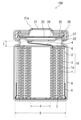
- FIG. 1 is a schematic vertical sectional view of an example of a sealed battery.
- the battery 100 includes a bottomed cylindrical battery case (battery can) 9, a cylindrical electrode body 10 housed in the battery case 9 together with an electrolytic solution (not shown), and a sealing member, and the battery case 9 is provided.
- the opening of is closed by a sealing member.
- the sealing member includes a terminal cap 21, a bottom plate 22, and a valve body 23.
- the sealing member further includes a spacer (valve support plate) 24 and a PTC element 25.
- the electrode body 10 may be configured such that the positive electrode 1 and the negative electrode 2 are wound around the separator 3 via the separator 3.
- the positive electrode lead 4 connected to the current collector 1a of the positive electrode 1 is connected to the bottom plate 22.
- the negative electrode lead 5 connected to the negative electrode 2 is connected to the case 9. Further, an upper insulating plate 6 and a lower insulating plate 7 are arranged on the upper part and the lower part of the electrode body 10 to prevent an internal short circuit, respectively.
- the bottom plate 22 is, for example, a ring-shaped member having an opening in the center, and is bent and folded back in the inner peripheral direction at the outer peripheral edge portion.
- the valve body 23 and the spacer 24 are sandwiched between the bottom plate 22 by the bent and extended folded portion, and the valve body 23 and the spacer 24 are fixed to the bottom plate 22.
- the valve body 23 is crimped to the bottom plate 22 via the spacer 24 and fixed to the bottom plate 22.
- the bottom plate 22 is electrically connected to one electrode (positive electrode 1) of the electrode body via the positive electrode lead 4, and is also electrically connected to the terminal cap 21 via the folded-back portion and the PTC element 25. ..
- the valve body 23 is, for example, a disk-shaped plate material having no opening.
- the pressure is applied to the portion of the valve body 23 that is not covered with the spacer 24 in the direction of rising outward.
- the internal pressure exceeds the desired valve operating pressure, at least a part of the valve body 23 breaks due to tensile stress.
- the gas in the battery 100 is discharged to the outside through the broken portion of the valve body 23 and the hole 21a of the terminal cap. As a result, the explosion-proof function is activated and the internal pressure is released.
- the PTC (Positive Temperature Coefficient) element 25 is a ring-shaped member and contains a material whose electrical resistance increases as the temperature rises. When an abnormally large current flows through the battery 100, the temperature inside the PTC element 25 rises due to heat generation. Along with this, the electric resistance of the PTC element 25 increases, so that the current flowing through the battery 100 is reduced.
- the terminal cap 21, the PTC element 25, and the bottom plate 22 to which the valve body 23 and the spacer 24 are fixed are overlapped and crimped to the battery case 9 via the gasket 26 to seal the opening of the battery case 9. There is.
- the material of the battery case 9 is not particularly limited, and examples thereof include iron and / or iron alloys (including stainless steel), aluminum, aluminum alloys (alloys containing trace amounts of other metals such as manganese and copper), and the like. ..
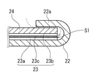
- FIG. 2 is a diagram showing the structures of the valve body 23, the spacer 24, and the bottom plate 22 in the sealed battery, and is a diagram for explaining a problem that occurs when the protective layer is not provided.
- the outer peripheral edge portion of the bottom plate 22 is shown in an enlarged manner.
- the valve body 23 is crimped to the bottom plate 22 via the spacer 24.
- the valve body 23 is an aluminum foil, and the surface facing the bottom plate 22 is covered with the first resin layer 23a, and the surface facing the spacer 24 is covered with the second resin layer 23b.
- the first resin layer 23a and the second resin layer 23b contain a compound having excellent corrosion resistance to an electrolytic solution such as polyethylene and polypropylene.
- the first resin layer 23a can be fixed to the bottom plate 22 by heat welding.
- the scattered electrolytic solution may enter the sealing member through the hole 21a provided in the terminal cap 21.
- the electrolytic solution may adhere to the surface of the second resin layer 23b of the valve body 23, for example. In this case, since the second resin layer 23b has corrosion resistance to the electrolytic solution, corrosion of the valve body 23 is suppressed.
- the electrolytic solution may also adhere to the end surface S1 (first end surface) which is the outer edge of the valve body 23 through the gap between the folded portion 22a of the bottom plate 22 and the spacer 24.
- the end surface S1 first end surface
- corrosion may proceed when the electrolytic solution comes into contact with the metal layer 23c.
- the valve body 23 may peel off from the bottom plate 22, and the valve operating pressure may decrease.
- a broken line arrow indicates the intrusion path of the electrolytic solution that reaches the end face S1 through the gap between the folded-back portion 22a and the spacer 24.
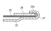
- 3A to 3C are views showing an example of the structure of the valve body 23, the spacer 24, and the bottom plate 22 in the sealed battery of the present embodiment, and in particular, the outer peripheral edge portion of the bottom plate 22 is enlarged and shown.
- the end face S1 which is the outer edge of the valve body 23 is covered with the protective layer 27 which has corrosion resistance to the electrolytic solution.
- the electrolytic solution that has entered through the gap between the folded-back portion 22a of the bottom plate 22 and the spacer 24 may adhere to the protective layer 27, but is prevented from coming into contact with the metal portion of the valve body 23. Therefore, the corrosion of the valve body via the end face S1 is suppressed, and the valve body 23 is suppressed from peeling from the bottom plate 22. As a result, the decrease in the valve operating pressure is also suppressed, and the valve operating pressure can be maintained at a desired value.
- the protective layer 27 covers the end surface S1 of the valve body 23 and also covers the end surface S2 (second end surface) which is the outer edge of the spacer.
- the protective layer 27 is also interposed in the space between the end face S2 and the bottom plate 22.
- the protective layer 27 can fill the space between the end face S2 and the bottom plate 22.
- the gap between the bottom plate 22 and the spacer 24 is closed by the protective layer 27. Therefore, the effect of suppressing corrosion of the valve body via the end face S1 is enhanced, and the valve body 23 is effectively suppressed from peeling from the bottom plate 22. As a result, the decrease in valve operating pressure can be effectively suppressed.
- the protective layer 27 covers the end surface S1 of the valve body 23 and the end surface S2 of the spacer 24, and is also interposed in the space between the end surface S2 and the bottom plate 22.
- the protective layer 27 also adheres to the upper surface of the spacer 24 (the surface on the side not facing the valve body 23) and is in contact with the folded portion of the bottom plate 22 above the upper surface. Thereby, the protective layer 27 can surely close the gap between the bottom plate 22 and the spacer 24. Therefore, corrosion of the valve body via the end face S1 can be reliably suppressed, and peeling of the valve body 23 from the bottom plate 22 is effectively suppressed. As a result, the decrease in valve operating pressure can be effectively suppressed.
- the extending distance of the protective layer 27 from the end surface S2 on the upper surface of the spacer 24 may be 0.02 mm or more, more preferably 0.1 mm or more, from the viewpoint of surely closing the gap between the bottom plate and the spacer 24. ..
- the protective layer 27 contains compound A having corrosion resistance to the electrolytic solution. Since compound A is stable to an electrolytic solution and has flexibility, it is preferable to contain a polyolefin such as polyproprene or polyethylene. Compound A may also contain a rubber-based material such as butadiene rubber. Among these, compound A most preferably contains polyethylene.
- FIGS. 3A to 3C can be realized by, for example, the manufacturing method shown below.
- 4A to 4D are process cross-sectional views showing a method of manufacturing a member (lower sealing member) in which the valve body 23 and the spacer 24 are integrated with the bottom plate 22.
- valve body 23 is arranged on the bottom plate 22, and the valve body 23 is fixed on the bottom plate 22 by heat welding. In this state, the outer peripheral portion of the bottom plate 22 is bent and extended substantially perpendicular to the other portion of the bottom plate 22.
- a protective layer 27 is formed on the outer periphery of the valve body 23, and as shown in FIG. 4C, the spacer 24 is arranged on the valve body 23.
- the protective layer may be formed by coating.
- the folded portion 22a of the bottom plate 22 is further bent in the inner peripheral direction, and the valve body 23 is crimped to the bottom plate 22 via the spacer 24 (and the protective layer 27).
- the structures shown in FIGS. 3A to 3C can be obtained.
- the positive electrode contains a positive electrode active material, and manganese dioxide can be used as the positive electrode active material.
- the positive electrode includes, for example, a positive electrode current collector and a positive electrode mixture layer attached to the positive electrode current collector.
- the positive electrode mixture layer may contain a resin material such as a fluororesin as a binder in addition to the positive electrode active material.
- the positive electrode mixture layer may contain a conductive material such as a carbon material as a conductive agent.
- the positive electrode current collector is, for example, an expanded metal made of stainless steel, a net, a punching metal, or the like.
- the negative electrode contains a negative electrode active material, and metallic lithium or a lithium alloy can be used as the negative electrode active material.
- the metallic lithium or lithium alloy is, for example, extruded into a long sheet and used as a negative electrode.
- the lithium alloy alloys such as Li—Al, Li—Sn, Li—Ni—Si, and Li—Pb are used, but a Li—Al alloy is preferable.
- the content of metal elements other than lithium contained in the lithium alloy is preferably 0.1% by mass or more and 5% by mass or less from the viewpoint of ensuring the discharge capacity and stabilizing the internal resistance.
- separator As the separator, a resin-made microporous membrane or a non-woven fabric is preferably used.
- the material (resin) of the separator polyolefin, polyamide, polyamideimide and the like are preferable.
- a non-aqueous solvent in which a lithium salt is dissolved may be used as the electrolytic solution.
- the non-aqueous solvent is not particularly limited, but propylene carbonate, ethylene carbonate, 1,2-dimethoxyethane, ⁇ -butyrolactone and the like can be used.
- As the lithium salt lithium borofluoride, lithium hexafluorophosphate, lithium trifluoromethanesulfonate, lithium bis (fluorosulfonyl) imide, lithium bis (trifluoromethylsulfonyl) imide and the like can be used.
- Batteries A1 to A4, B1 (1) Preparation of positive electrode 100 parts by mass of electrolytic manganese dioxide and 5 parts by mass of Ketjen Black, which is a conductive agent, are mixed, and 5 parts by mass of polytetrafluoroethylene, which is a binder, and an appropriate amount of pure water are added. , And kneaded to prepare a wet positive electrode mixture.
- a positive electrode mixture was pressure-bonded to an expanded metal (positive electrode current collector) made of SUS with a roll and dried to obtain a positive electrode.
- the thickness of the positive electrode after rolling was 520 ⁇ m, and the weight of the positive electrode mixture per unit area was 0.134 g / cm 2 .
- the positive electrode was cut into a strip having a width of 38 mm and a length of 192 mm, and then a part of the filled positive electrode mixture was peeled off to resist a SUS tab lead to the exposed portion of the positive electrode current collector. Welded.
- Electrode Body An electrode body was prepared by stacking a positive electrode and a negative electrode via a separator and winding them in a spiral shape along a winding core having a diameter of 3.5 mm. A polyethylene microporous membrane having a thickness of 25 ⁇ m was used as the separator.
- Lithium trifluoromethanesulfonate was added as a lithium salt to a non-aqueous solvent in which propylene carbonate (PC) and 1,2-dimethoxyethane (DME) were mixed at a volume ratio of 4: 6.
- An electrolytic solution was prepared by dissolving at a concentration of 7 mol / L. The viscosity of the electrolytic solution was 0.0014 Pa ⁇ s at 20 ° C.
- a ring-shaped bottom plate (made of SUS, thickness 0.3 mm) having an inner diameter of 4.0 mm was prepared.
- a valve body, a protective layer made of polypropylene (PP), and a spacer (made of SUS, thickness 0.3 mm) are arranged on the bottom plate as shown in FIGS. 4A to 4C, and the outer peripheral edge of the bottom plate is arranged as shown in FIG. 4D.
- the valve body was crimped via the spacer by bending the portion in the inner peripheral direction, and the lower sealing member A having the structure shown in FIG. 3A was produced.
- the valve body was an aluminum foil having a thickness of 25 ⁇ m, and both sides thereof were coated with a polyethylene (PE) film having a thickness of 50 ⁇ m.
- PE polyethylene
- the inner diameter d of the hollow portion of the electrode body was approximately equal to the diameter of the winding core used for manufacturing the electrode body, and was 3.5 mm.
- the inner diameter D of the battery case was 16.0 mm, and the distance L between the bottom plate and the electrode body was 2.5 mm.
- the total area of the holes provided in the terminal cap was 1.8 mm 2 .
- the lower sealing member is designed so that the valve operating pressure (safety valve strength) is 2.0 MPa.
- the lower sealing member B having the structure shown in FIG. 3B and the lower sealing member C having the structure shown in FIG. 3C were produced by preparing those having different widths of the protective layer. Further, in the lower sealing member C, the lower sealing member D in which the material of the protective layer was changed to polyethylene was produced.
- lithium primary batteries A2 for testing were produced in the same manner as the lithium primary battery A1 except that the lower sealing member B was used.
- lithium primary batteries A3 for testing were produced in the same manner as the lithium primary battery A1 except that the lower sealing member C was used.
- lithium primary batteries A4 for testing were produced in the same manner as the lithium primary battery A1 except that the lower sealing member D was used.
- lithium primary batteries B1 for testing were manufactured in the same manner as the lithium primary battery A1 except that the lower sealing member E without the protective layer was manufactured and the lower sealing member E was used.
- Batteries A5, B2, B3 In the lithium primary battery A1, the distance L between the bottom plate and the electrode body was changed to 2.0 mm. The distance L was changed by adjusting the height of the groove (reduced diameter portion) of the battery case formed to crimp the sealing member via the gasket.
- lithium primary batteries A5 for testing were prepared in the same manner as the lithium primary battery A1, and the safety valve strength was evaluated in the same manner.
- the distance L between the bottom plate and the electrode body was changed to 2.3 mm and 2.0 mm, respectively, to obtain lithium primary batteries B2 and B3.
- Table 2 shows the evaluation results of the safety valve strength for the batteries A5, B2, and B3.
- Table 2 the value of the distance L between the bottom plate and the electrode body in each battery is also shown.
- Batteries A6, B4, B5 >> In the lithium primary battery A1, the inner diameter d of the hollow portion of the electrode body was set to 2.5 mm.
- the outer diameter of the electrode body was increased to 530 ⁇ m after rolling of the positive electrode so that the outer diameter of the electrode body was substantially the same as that of the battery A1, and the thickness of the negative electrode was changed to 210 ⁇ m.
- lithium primary batteries A6 for testing were prepared in the same manner as the lithium primary battery A1, and the safety valve strength was evaluated in the same manner.
- the inner diameter d of the hollow portion of the electrode body was changed to 3.1 mm to obtain the lithium primary battery B4.
- the inner diameter d of the hollow portion of the electrode body was changed to 2.5 mm to obtain the lithium primary battery B5.
- the thickness of the positive electrode after rolling was increased to 525 ⁇ m and the thickness of the negative electrode was changed to 205 ⁇ m so that the outer diameter of the electrode body was substantially the same as that of the battery B1 while the inner diameter d was reduced.
- the thickness of the positive electrode after rolling was increased to 530 ⁇ m, and the thickness of the negative electrode was changed to 210 ⁇ m.
- Table 3 shows the evaluation results of the safety valve strength for the batteries A6, B4, and B5.
- Table 3 shows the evaluation results of the safety valve strength for the batteries A6, B4, and B5.
- the inner diameter d of the hollow portion of the electrode body in each battery, the inner diameter D of the battery case, and the value of the ratio d / D are also shown.
- Batteries A7, B6, B7 >> In the lithium primary battery A1, the total area of the holes of the terminal caps was set to 3.0 mm 2 .
- lithium primary batteries A7 for testing were prepared in the same manner as the lithium primary battery A1, and the safety valve strength was evaluated in the same manner.
- the total area of the holes of the terminal caps was changed to 2.5 mm 2 and 3.0 mm 2 , respectively, to obtain lithium primary batteries B6 and B7.
- Table 4 shows the evaluation results of the safety valve strength for the batteries A7, B6, and B7. Table 4 also shows the total area of the holes in the terminal caps of each battery.
- Batteries A8, B8, B9 >> In the lithium primary battery A1, the thickness of the separator in the electrode body was set to 0.015 mm.
- lithium primary batteries A8 for testing were prepared in the same manner as the lithium primary battery A1, and the safety valve strength was evaluated in the same manner.
- the thickness of the separator in the electrode body was changed to 0.02 mm and 0.015 mm, respectively, to obtain lithium primary batteries B8 and B9.
- Table 5 shows the evaluation results of the safety valve strength for the batteries A8, B8, and B9. Table 5 also shows the thickness of the separator in each battery.
- lithium primary batteries A9 for testing were prepared in the same manner as the lithium primary battery A1, and the safety valve strength was evaluated in the same manner.
- an electrolytic solution having a viscosity at 20 ° C. of 0.0012 Pa ⁇ s was prepared, and the adjusted electrolytic solution was used to obtain a lithium primary battery B10.
- an electrolytic solution having a viscosity at 20 ° C. of 0.001 Pa ⁇ s was prepared, and the adjusted electrolytic solution was used to obtain a lithium primary battery B11.
- Table 6 shows the evaluation results of the safety valve strength for the batteries A9, B10, and B11. Table 6 also shows the viscosities of the electrolytic solution in each battery.
- Batteries A10, B12, B13 In the lithium primary battery A1, the weight of the positive electrode mixture in the positive electrode was changed so that the weight of the positive electrode mixture per unit area was 0.162 g / cm 2 .
- lithium primary batteries A10 for testing were prepared in the same manner as the lithium primary battery A1, and the safety valve strength was evaluated in the same manner.
- the weight of the positive electrode mixture occupying the positive electrode is changed, and the positive electrode mixture weight per unit area is changed to 0.148 g / cm 2 and 0.162 g / cm 2 , respectively.
- B12 and B13 were obtained.
- Table 7 shows the evaluation results of the safety valve strength for the batteries A10, B12, and B13. Table 7 also shows the weight of the positive electrode mixture per unit area in each battery.
- the safety valve strength could be maintained high in the batteries A1 to A4 in which the protective layer containing the compound A was formed so as to cover at least the end face of the valve body. On the other hand, in the battery B1 without the protective layer, the safety valve strength was low.
- the battery A2 which is formed so that the protective layer covers the end face of the valve body and also covers the end face of the spacer to fill the space between the end face of the spacer and the bottom plate, is a battery formed so that the protective layer covers only the end face of the valve body. Compared with A1, the safety valve strength could be maintained high. Further, the battery A3 formed so that the protective layer fills the gap between the upper surface of the spacer and the folded portion of the bottom plate can maintain a higher safety valve strength than the battery A2.
- the battery A4 in which the protective layer is formed so as to fill the gap between the upper surface of the spacer and the folded portion of the bottom plate and polyethylene is used as the protective layer maintains the safety valve strength substantially the same as immediately after production. rice field.
- the safety valve strength was lower than that of the battery B1 by setting the distance L between the bottom plate and the electrode body to 2.3 mm or less.
- the same high safety valve strength as the battery A1 could be maintained even when the distance L between the bottom plate and the electrode body was set to 2.3 mm or less.
- the safety valve strength is set to 0.2 or less by setting the ratio d / D of the inner diameter d of the hollow portion of the electrode body to the inner diameter D of the battery case to 0.2 or less.
- the same high safety valve strength as the battery A1 could be maintained even when the d / D was set to 0.2 or less.
- the safety valve strength was lower than that of the battery B1 by setting the total area of the holes of the terminal caps to 2 mm 2 or more.
- the battery A7 provided with the protective layer even when the total hole area was 2 mm 2 or more, the same high safety valve strength as the battery A1 could be maintained.
- the safety valve strength was lower than that of the battery B1 by setting the thickness of the separator to 0.02 mm or less.
- the thickness of the separator was 0.02 mm or less, even when the thickness of the separator was 0.02 mm or less, the same high safety valve strength as that of the battery A1 could be maintained.
- the safety valve strength was lower than that of the battery B1 by setting the viscosity of the electrolytic solution to 0.0012 Pa ⁇ s or less.
- the viscosity of the electrolytic solution was 0.0012 Pa ⁇ s or less, the same high safety valve strength as that of the battery A1 could be maintained.
- the safety valve strength was lower than that of the battery B1 by setting the positive electrode mixture weight per unit area to 0.14 g / cm 2 or more.
- the battery A9 provided with the protective layer even when the positive electrode mixture weight per unit area was 0.14 g / cm 2 or more, the same high safety valve strength as the battery A1 could be maintained.
- the sealed battery according to the present invention has a stable operating pressure of a safety valve, and is therefore suitable as a power source for various electronic devices.
Landscapes
- Chemical & Material Sciences (AREA)
- Chemical Kinetics & Catalysis (AREA)
- Electrochemistry (AREA)
- General Chemical & Material Sciences (AREA)
- Composite Materials (AREA)
- Gas Exhaust Devices For Batteries (AREA)
- Sealing Battery Cases Or Jackets (AREA)
- Cell Separators (AREA)
- Primary Cells (AREA)
- Connection Of Batteries Or Terminals (AREA)
Priority Applications (4)
| Application Number | Priority Date | Filing Date | Title |
|---|---|---|---|
| JP2022541418A JP7411969B2 (ja) | 2020-08-06 | 2021-07-16 | 密閉型電池 |
| US18/006,394 US20230268594A1 (en) | 2020-08-06 | 2021-07-16 | Hermetically sealed battery |
| CN202180058090.8A CN116057766A (zh) | 2020-08-06 | 2021-07-16 | 密闭型电池 |
| EP21853588.8A EP4195392A4 (en) | 2020-08-06 | 2021-07-16 | HERMETIC SEALED BATTERY |
Applications Claiming Priority (2)
| Application Number | Priority Date | Filing Date | Title |
|---|---|---|---|
| JP2020-133514 | 2020-08-06 | ||
| JP2020133514 | 2020-08-06 |
Publications (1)
| Publication Number | Publication Date |
|---|---|
| WO2022030231A1 true WO2022030231A1 (ja) | 2022-02-10 |
Family
ID=80117290
Family Applications (1)
| Application Number | Title | Priority Date | Filing Date |
|---|---|---|---|
| PCT/JP2021/026854 Ceased WO2022030231A1 (ja) | 2020-08-06 | 2021-07-16 | 密閉型電池 |
Country Status (5)
| Country | Link |
|---|---|
| US (1) | US20230268594A1 (https=) |
| EP (1) | EP4195392A4 (https=) |
| JP (1) | JP7411969B2 (https=) |
| CN (1) | CN116057766A (https=) |
| WO (1) | WO2022030231A1 (https=) |
Cited By (4)
| Publication number | Priority date | Publication date | Assignee | Title |
|---|---|---|---|---|
| JP2023167557A (ja) * | 2022-05-12 | 2023-11-24 | パナソニックIpマネジメント株式会社 | 密閉型電池 |
| US12300793B1 (en) | 2024-02-02 | 2025-05-13 | Hamedata Technology Co., Limited | 1.5V lithium battery and manufacturing method thereof |
| EP4481871A4 (en) * | 2022-02-18 | 2025-08-27 | Panasonic Ip Man Co Ltd | CYLINDRICAL SECONDARY BATTERY WITH NON-AQUEOUS ELECTROLYTE |
| WO2026034148A1 (ja) * | 2024-08-09 | 2026-02-12 | パナソニックIpマネジメント株式会社 | 密閉型電池 |
Citations (5)
| Publication number | Priority date | Publication date | Assignee | Title |
|---|---|---|---|---|
| JPH11283599A (ja) * | 1998-03-31 | 1999-10-15 | Sanyo Electric Co Ltd | リチウムイオン電池 |
| WO2000072388A1 (fr) * | 1999-05-24 | 2000-11-30 | Toyo Kohan Co.,Ltd. | Procede de formation de revetement protecteur pour dispositif de valve de securite de cellule, meme dispositif ainsi revetu, plaque d'etancheite de cellule equipee du dispositif ainsi revetu, et cellule fermee ainsi equipee |
| JP2005347098A (ja) | 2004-06-03 | 2005-12-15 | Matsushita Electric Ind Co Ltd | 電池および電池用組立封口板 |
| JP2007184270A (ja) * | 2005-12-29 | 2007-07-19 | Samsung Sdi Co Ltd | リチウム二次電池 |
| JP2018014160A (ja) * | 2014-11-27 | 2018-01-25 | 三洋電機株式会社 | 円筒形非水電解質二次電池 |
Family Cites Families (7)
| Publication number | Priority date | Publication date | Assignee | Title |
|---|---|---|---|---|
| JP2574343B2 (ja) * | 1987-12-08 | 1997-01-22 | 松下電器産業株式会社 | 有機電解質電池 |
| JP3594440B2 (ja) * | 1997-03-06 | 2004-12-02 | 三洋電機株式会社 | 密閉型電池 |
| US20110143218A1 (en) * | 2009-12-14 | 2011-06-16 | Issaev Nikolai N | Battery |
| KR101281038B1 (ko) * | 2010-12-07 | 2013-07-09 | 주식회사 엘지화학 | 캡 조립체 및 이를 이용한 이차 전지 |
| JP6354982B2 (ja) * | 2014-04-24 | 2018-07-11 | トヨタ自動車株式会社 | 非水電解液二次電池およびその製造方法 |
| KR20160108857A (ko) * | 2015-03-09 | 2016-09-21 | 주식회사 엘지화학 | 복수의 양극 탭들과 음극 탭들을 포함하는 원통형 이차전지 |
| WO2020075731A1 (ja) * | 2018-10-09 | 2020-04-16 | 大日本印刷株式会社 | 電池用弁体、その製造方法及び電池 |
-
2021
- 2021-07-16 US US18/006,394 patent/US20230268594A1/en active Pending
- 2021-07-16 WO PCT/JP2021/026854 patent/WO2022030231A1/ja not_active Ceased
- 2021-07-16 JP JP2022541418A patent/JP7411969B2/ja active Active
- 2021-07-16 CN CN202180058090.8A patent/CN116057766A/zh active Pending
- 2021-07-16 EP EP21853588.8A patent/EP4195392A4/en active Pending
Patent Citations (5)
| Publication number | Priority date | Publication date | Assignee | Title |
|---|---|---|---|---|
| JPH11283599A (ja) * | 1998-03-31 | 1999-10-15 | Sanyo Electric Co Ltd | リチウムイオン電池 |
| WO2000072388A1 (fr) * | 1999-05-24 | 2000-11-30 | Toyo Kohan Co.,Ltd. | Procede de formation de revetement protecteur pour dispositif de valve de securite de cellule, meme dispositif ainsi revetu, plaque d'etancheite de cellule equipee du dispositif ainsi revetu, et cellule fermee ainsi equipee |
| JP2005347098A (ja) | 2004-06-03 | 2005-12-15 | Matsushita Electric Ind Co Ltd | 電池および電池用組立封口板 |
| JP2007184270A (ja) * | 2005-12-29 | 2007-07-19 | Samsung Sdi Co Ltd | リチウム二次電池 |
| JP2018014160A (ja) * | 2014-11-27 | 2018-01-25 | 三洋電機株式会社 | 円筒形非水電解質二次電池 |
Non-Patent Citations (1)
| Title |
|---|
| See also references of EP4195392A4 |
Cited By (4)
| Publication number | Priority date | Publication date | Assignee | Title |
|---|---|---|---|---|
| EP4481871A4 (en) * | 2022-02-18 | 2025-08-27 | Panasonic Ip Man Co Ltd | CYLINDRICAL SECONDARY BATTERY WITH NON-AQUEOUS ELECTROLYTE |
| JP2023167557A (ja) * | 2022-05-12 | 2023-11-24 | パナソニックIpマネジメント株式会社 | 密閉型電池 |
| US12300793B1 (en) | 2024-02-02 | 2025-05-13 | Hamedata Technology Co., Limited | 1.5V lithium battery and manufacturing method thereof |
| WO2026034148A1 (ja) * | 2024-08-09 | 2026-02-12 | パナソニックIpマネジメント株式会社 | 密閉型電池 |
Also Published As
| Publication number | Publication date |
|---|---|
| JPWO2022030231A1 (https=) | 2022-02-10 |
| US20230268594A1 (en) | 2023-08-24 |
| CN116057766A (zh) | 2023-05-02 |
| JP7411969B2 (ja) | 2024-01-12 |
| EP4195392A4 (en) | 2024-01-17 |
| EP4195392A1 (en) | 2023-06-14 |
Similar Documents
| Publication | Publication Date | Title |
|---|---|---|
| JP7411969B2 (ja) | 密閉型電池 | |
| CN109891640B (zh) | 非水电解质二次电池用电极以及非水电解质二次电池 | |
| US7060388B2 (en) | Nonaqueous electrolyte secondary battery | |
| EP2136429A1 (en) | Electrode assembly and lithium secondary battery with same | |
| US20040126650A1 (en) | Electrode assembly for lithium ion cell and lithium cell using the same | |
| US7927734B2 (en) | Lithium secondary battery and fabrication method thereof | |
| US20100233524A1 (en) | Cylindrical non-aqueous electrolyte secondary battery | |
| JPH02207450A (ja) | Ptc素子付き円筒形有機電解液電池 | |
| JP2009545123A (ja) | 正極容器を備えた電気化学セル | |
| CN111164796A (zh) | 非水电解质二次电池 | |
| JP2020205269A (ja) | 捲回型電池 | |
| JP2013533588A (ja) | コア補強を有するリチウム−二硫化鉄セル設計 | |
| EP4471971A1 (en) | Battery and current collector | |
| CN105789498A (zh) | 圆柱形锂离子二次电池 | |
| US20250055040A1 (en) | Power storage device | |
| CN109891639B (zh) | 非水电解质二次电池用电极以及非水电解质二次电池 | |
| EP4318702A1 (en) | Cylindrical battery | |
| JP4580699B2 (ja) | 非水電解質二次電池 | |
| JP5252691B2 (ja) | 円筒形非水電解液一次電池およびその製造方法 | |
| JP2006228520A (ja) | 二次電池 | |
| EP4300644A1 (en) | Cylindrical battery | |
| JP2000357505A (ja) | 非水電解液二次電池 | |
| US10497924B2 (en) | Secondary battery | |
| JP2007128747A (ja) | 電池 | |
| KR100601515B1 (ko) | 이차 전지 |
Legal Events
| Date | Code | Title | Description |
|---|---|---|---|
| 121 | Ep: the epo has been informed by wipo that ep was designated in this application |
Ref document number: 21853588 Country of ref document: EP Kind code of ref document: A1 |
|
| ENP | Entry into the national phase |
Ref document number: 2022541418 Country of ref document: JP Kind code of ref document: A |
|
| WWE | Wipo information: entry into national phase |
Ref document number: 2021853588 Country of ref document: EP |
|
| NENP | Non-entry into the national phase |
Ref country code: DE |