WO2022030185A1 - 圧縮機、圧縮機の製造方法 - Google Patents
圧縮機、圧縮機の製造方法 Download PDFInfo
- Publication number
- WO2022030185A1 WO2022030185A1 PCT/JP2021/026024 JP2021026024W WO2022030185A1 WO 2022030185 A1 WO2022030185 A1 WO 2022030185A1 JP 2021026024 W JP2021026024 W JP 2021026024W WO 2022030185 A1 WO2022030185 A1 WO 2022030185A1
- Authority
- WO
- WIPO (PCT)
- Prior art keywords
- auxiliary bearing
- bearing member
- housing
- compression mechanism
- peripheral surface
- Prior art date
- Legal status (The legal status is an assumption and is not a legal conclusion. Google has not performed a legal analysis and makes no representation as to the accuracy of the status listed.)
- Ceased
Links
Images


Classifications
-
- F—MECHANICAL ENGINEERING; LIGHTING; HEATING; WEAPONS; BLASTING
- F04—POSITIVE - DISPLACEMENT MACHINES FOR LIQUIDS; PUMPS FOR LIQUIDS OR ELASTIC FLUIDS
- F04C—ROTARY-PISTON, OR OSCILLATING-PISTON, POSITIVE-DISPLACEMENT MACHINES FOR LIQUIDS; ROTARY-PISTON, OR OSCILLATING-PISTON, POSITIVE-DISPLACEMENT PUMPS
- F04C18/00—Rotary-piston pumps specially adapted for elastic fluids
- F04C18/02—Rotary-piston pumps specially adapted for elastic fluids of arcuate-engagement type, i.e. with circular translatory movement of co-operating members, each member having the same number of teeth or tooth-equivalents
- F04C18/0207—Rotary-piston pumps specially adapted for elastic fluids of arcuate-engagement type, i.e. with circular translatory movement of co-operating members, each member having the same number of teeth or tooth-equivalents both members having co-operating elements in spiral form
- F04C18/0215—Rotary-piston pumps specially adapted for elastic fluids of arcuate-engagement type, i.e. with circular translatory movement of co-operating members, each member having the same number of teeth or tooth-equivalents both members having co-operating elements in spiral form where only one member is moving
-
- F—MECHANICAL ENGINEERING; LIGHTING; HEATING; WEAPONS; BLASTING
- F04—POSITIVE - DISPLACEMENT MACHINES FOR LIQUIDS; PUMPS FOR LIQUIDS OR ELASTIC FLUIDS
- F04C—ROTARY-PISTON, OR OSCILLATING-PISTON, POSITIVE-DISPLACEMENT MACHINES FOR LIQUIDS; ROTARY-PISTON, OR OSCILLATING-PISTON, POSITIVE-DISPLACEMENT PUMPS
- F04C23/00—Combinations of two or more pumps, each being of rotary-piston or oscillating-piston type, specially adapted for elastic fluids; Pumping installations specially adapted for elastic fluids; Multi-stage pumps specially adapted for elastic fluids
- F04C23/008—Hermetic pumps
-
- F—MECHANICAL ENGINEERING; LIGHTING; HEATING; WEAPONS; BLASTING
- F04—POSITIVE - DISPLACEMENT MACHINES FOR LIQUIDS; PUMPS FOR LIQUIDS OR ELASTIC FLUIDS
- F04C—ROTARY-PISTON, OR OSCILLATING-PISTON, POSITIVE-DISPLACEMENT MACHINES FOR LIQUIDS; ROTARY-PISTON, OR OSCILLATING-PISTON, POSITIVE-DISPLACEMENT PUMPS
- F04C29/00—Component parts, details or accessories of pumps or pumping installations, not provided for in groups F04C18/00 - F04C28/00
- F04C29/0042—Driving elements, brakes, couplings, transmissions specially adapted for pumps
- F04C29/005—Means for transmitting movement from the prime mover to driven parts of the pump, e.g. clutches, couplings, transmissions
-
- F—MECHANICAL ENGINEERING; LIGHTING; HEATING; WEAPONS; BLASTING
- F04—POSITIVE - DISPLACEMENT MACHINES FOR LIQUIDS; PUMPS FOR LIQUIDS OR ELASTIC FLUIDS
- F04C—ROTARY-PISTON, OR OSCILLATING-PISTON, POSITIVE-DISPLACEMENT MACHINES FOR LIQUIDS; ROTARY-PISTON, OR OSCILLATING-PISTON, POSITIVE-DISPLACEMENT PUMPS
- F04C2230/00—Manufacture
- F04C2230/60—Assembly methods
- F04C2230/603—Centering; Aligning
-
- F—MECHANICAL ENGINEERING; LIGHTING; HEATING; WEAPONS; BLASTING
- F04—POSITIVE - DISPLACEMENT MACHINES FOR LIQUIDS; PUMPS FOR LIQUIDS OR ELASTIC FLUIDS
- F04C—ROTARY-PISTON, OR OSCILLATING-PISTON, POSITIVE-DISPLACEMENT MACHINES FOR LIQUIDS; ROTARY-PISTON, OR OSCILLATING-PISTON, POSITIVE-DISPLACEMENT PUMPS
- F04C2240/00—Components
- F04C2240/30—Casings or housings
-
- F—MECHANICAL ENGINEERING; LIGHTING; HEATING; WEAPONS; BLASTING
- F04—POSITIVE - DISPLACEMENT MACHINES FOR LIQUIDS; PUMPS FOR LIQUIDS OR ELASTIC FLUIDS
- F04C—ROTARY-PISTON, OR OSCILLATING-PISTON, POSITIVE-DISPLACEMENT MACHINES FOR LIQUIDS; ROTARY-PISTON, OR OSCILLATING-PISTON, POSITIVE-DISPLACEMENT PUMPS
- F04C2240/00—Components
- F04C2240/50—Bearings
- F04C2240/52—Bearings for assemblies with supports on both sides
-
- F—MECHANICAL ENGINEERING; LIGHTING; HEATING; WEAPONS; BLASTING
- F04—POSITIVE - DISPLACEMENT MACHINES FOR LIQUIDS; PUMPS FOR LIQUIDS OR ELASTIC FLUIDS
- F04C—ROTARY-PISTON, OR OSCILLATING-PISTON, POSITIVE-DISPLACEMENT MACHINES FOR LIQUIDS; ROTARY-PISTON, OR OSCILLATING-PISTON, POSITIVE-DISPLACEMENT PUMPS
- F04C2240/00—Components
- F04C2240/60—Shafts
Definitions
- the present disclosure relates to a compressor that compresses and discharges the sucked fluid and a method for manufacturing the compressor.
- Patent Document 1 discloses a scroll type compressor.
- This compressor includes a compression mechanism unit, an electric motor unit, a drive shaft for transmitting a driving force output by the electric motor unit to the compression mechanism unit, and a housing for accommodating the compression mechanism unit and the like.
- One side of the drive shaft in the axial direction is rotatably supported by a main bearing formed in a main bearing member forming a part of the compression mechanism portion, and the other side in the axial direction is a tubular body portion of the auxiliary bearing member. It is rotatably supported by an auxiliary bearing formed inside the.
- the housing includes a bottomed tubular housing body portion in which one side in the axial direction of the drive shaft opens, and an auxiliary bearing member is integrally formed with the bottom surface of the bottom portion of the housing body portion.
- a centering gap for aligning the axis of the main bearing and the axis of the sub-bearing is formed between the compression mechanism portion and the inner peripheral surface of the tubular portion of the housing main body portion.
- the axis of the main bearing is detected while the compression mechanism portion is displaced relative to the inner peripheral surface of the tubular portion of the housing main body, and the spindle center is detected. Align the axis of the sub-bearing with the axis of the auxiliary bearing, and fix it to the housing body while maintaining that state.
- the present inventors reduce the gap between the compression mechanism portion and the housing main body portion, and at the same time, coaxialize the axial center of the insertion portion into which the compression mechanism portion of the housing main body portion is inserted with the axial center of the auxiliary bearing.
- the insertion portion of the compression mechanism portion and the inner peripheral surface of the auxiliary bearing of the housing main body are each processed with high accuracy. There is a need to.
- the purpose of the present disclosure is to ensure the accuracy of the bearing that supports the drive shaft on the bottom portion side of the housing portion in the compressor having the bottomed tubular housing portion without introducing dedicated equipment.
- the compressor is The compression mechanism (30) that compresses the fluid,
- the motor unit (20) that outputs the driving force that drives the compression mechanism unit, and
- a drive shaft (14) that transmits the driving force output by the motor unit to the compression mechanism unit
- a housing (12) for accommodating a compression mechanism unit, a motor unit unit, and a drive shaft is provided.
- the housing includes a bottomed tubular first housing portion (121) that opens on one side in the axial direction of the drive shaft, and a second housing portion (122) that covers the opening of the first housing portion.
- One side of the drive shaft in the axial direction is rotatably supported by a main bearing (361a) integrally formed or fixed to a main bearing member (36) that constitutes a part of the compression mechanism.
- the other side of the drive shaft in the axial direction can be rotated by an auxiliary bearing (16a) integrally formed or fixed to the inside of the auxiliary bearing member (16) including a tubular body portion (161).
- the compression mechanism portion including the main bearing member is arranged inside the cylindrical portion (121b) of the first housing portion.
- the auxiliary bearing member is formed separately from the first housing portion and is fixed to the bottom surface of the bottom portion (121c) of the first housing portion.
- the auxiliary bearing member including the auxiliary bearing is configured separately from the first housing portion, the inner peripheral surface of the auxiliary bearing can be machined with the auxiliary bearing member removed from the housing. It is possible to accurately process the inner peripheral surface of the auxiliary bearing without introducing dedicated equipment.
- the compression mechanism (30) that compresses the fluid
- the motor unit (20) that outputs the driving force that drives the compression mechanism unit
- a drive shaft (14) that transmits the driving force output by the motor unit to the compression mechanism unit
- a housing (12) for accommodating a compression mechanism unit, a motor unit unit, and a drive shaft is provided.
- the housing includes a bottomed tubular first housing portion (121) that opens on one side in the axial direction of the drive shaft, and a second housing portion (122) that covers the opening of the first housing portion.
- One side of the drive shaft in the axial direction is rotatably supported by a main bearing (361a) integrally formed or fixed to a main bearing member (36) that constitutes a part of the compression mechanism.
- the other side of the drive shaft in the axial direction can be rotated by an auxiliary bearing (16a) integrally formed or fixed to the inside of the auxiliary bearing member (16) including a tubular body portion (161).
- the compression mechanism portion including the main bearing member is arranged inside the cylindrical portion (121b) of the first housing portion.
- the auxiliary bearing member is a method for manufacturing a compressor that is configured separately from the first housing portion.
- Aligning the axis of the auxiliary bearing with the axis of the inner peripheral surface of the insertion site where the compression mechanism is inserted out of the tubular part It includes fixing the auxiliary bearing member to the inner surface of the bottom portion of the first housing portion in a state where the axial center of the auxiliary bearing and the axial center of the inner peripheral surface of the insertion portion are aligned.
- the inner peripheral surface of the auxiliary bearing of the auxiliary bearing member can be processed before it is attached to the first housing portion, the inner peripheral surface of the auxiliary bearing can be accurately processed without introducing dedicated equipment. It becomes possible to do.
- the refrigeration cycle device constitutes a steam compression type refrigeration cycle.
- the refrigeration cycle device is decompressed by a compressor 10 that compresses and discharges a refrigerant as a fluid, a radiator that dissipates the refrigerant discharged from the compressor 10, a decompression device that decompresses the refrigerant that flows out of the radiator, and a decompression device. It contains an evaporator that evaporates the refrigerant.
- the main component of the refrigerant used in the refrigeration cycle device is carbon dioxide. Carbon dioxide becomes a supercritical state at a lower temperature than Freon-based refrigerants.
- the refrigerant is mixed with lubricating oil that lubricates each sliding portion inside the compressor 10. Part of the lubricating oil circulates in the cycle together with the refrigerant.
- the refrigerant may be a fluorocarbon-based refrigerant.
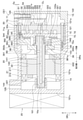
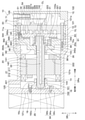
- FIG. 1 is an axial cross-sectional view showing a cross section cut along the axial center CL of the drive shaft 14 of the compressor 10.
- the vertical arrows in FIG. 1 indicate the vertical DRv when the compressor 10 is mounted on the vehicle.
- the arrow “DRa” in FIG. 1 indicates the axial DRa of the drive shaft 14.
- the compressor 10 includes a housing 12, a drive shaft 14, an electric motor unit 20, an inverter 25, and a compression mechanism unit 30.
- a drive shaft 14, an electric motor unit 20, and a compression mechanism unit 30 are housed inside the housing 12.
- the compressor 10 is an electric compressor.
- the drive shaft 14 rotates with the electric motor unit 20 as a power source.
- the compression mechanism unit 30 is driven as the drive shaft 14 rotates.
- the compressor 10 has a horizontal structure in which the axial center CL of the drive shaft 14 extends in a substantially horizontal direction, and the compression mechanism unit 30 and the motor unit 20 are arranged side by side in a substantially horizontal direction.
- the substantially horizontal direction is a direction that intersects the direction of gravity.
- the housing 12 constitutes the outer shell of the compressor 10.
- the housing 12 has a first housing portion 121 and a second housing portion 122.
- the first housing portion 121 and the second housing portion 122 are made of aluminum or an aluminum alloy.
- the first housing portion 121 has a bottomed cylinder shape in which one side of the drive shaft 14 in the axial direction DRa opens.
- the first housing portion 121 has a cup-shaped shape having a U-shaped cross section.
- the first housing portion 121 has a cylindrical tubular portion 121b and a bottom portion 121c.
- the tubular portion 121b has an opening 121a on one side of the axial DRa.
- the bottom portion 121c is connected to the other end of the axial DRa in the tubular portion 121b.
- the first housing portion 121 is configured as an integrally molded product in which the tubular portion 121b and the bottom portion 121c are seamlessly molded. A part of the outer surface of the bottom portion 121c is flat so that the inverter 25 can be brought into close contact with the bottom portion 121c.
- the first housing portion 121 has a stepped shape in which a step portion 80 is formed on the tubular portion 121b. That is, the first housing portion 121 has a first inner peripheral surface 82, a second inner peripheral surface 83, and a stepped surface 81. The distances of the first inner peripheral surface 82, the stepped surface 81, and the second inner peripheral surface 83 from the bottom portion 121c are reduced in this order. In other words, the distances of the first inner peripheral surface 82, the stepped surface 81, and the second inner peripheral surface 83 from the opening 121a increase in this order.
- the first inner peripheral surface 82 and the second inner peripheral surface 83 are formed in a cylindrical shape so as to be concentric circles about the axial center CL of the drive shaft 14.
- the first inner peripheral surface 82 is a portion of the first housing portion 121 where the motor portion 20 is arranged.
- the first inner peripheral surface 82 has a cylindrical shape.
- the second inner peripheral surface 83 is located on one side of the axial DRa with respect to the first inner peripheral surface 82.
- the second inner peripheral surface 83 has a cylindrical shape.
- the second inner peripheral surface 83 is the inner peripheral surface of the insertion portion of the first housing portion 121 into which the compression mechanism portion 30 is inserted.
- the outer diameter of the compression mechanism portion 30 is larger than the outer diameter of the motor portion 20. Therefore, the diameter of the second inner peripheral surface 83 is larger than the diameter of the first inner peripheral surface 82.
- the step surface 81 connects the first inner peripheral surface 82 and the second inner peripheral surface 83.
- the step surface 81 extends in a direction orthogonal to the axial DRa.
- the step surface 81 is in direct contact with the bearing fixing portion 362 of the main bearing member 36 described later.
- the stepped surface 81 may be in contact with the bearing fixing portion 362 via an inclusion.
- the insertion portion of the tubular portion 121b into which the compression mechanism portion 30 is inserted is a portion of the tubular portion 121b located on one side (that is, the opening 121a side) of the axial DRa with respect to the stepped surface 81.
- the compression mechanism portion 30 including the main bearing member 36 is arranged on the inner peripheral surface of the tubular portion 121b, and the auxiliary bearing member 16 including the tubular body portion 161 is fixed to the bottom portion 121c.
- the cylindrical portion 121b constitutes the tubular portion of the first housing portion 121
- the bottom portion 121c constitutes the bottom portion of the first housing portion 121.
- the second housing portion 122 covers the opening of the first housing portion 121 at a position on one side of the axial DRa with respect to the first housing portion 121.
- the second housing portion 122 is fastened and fixed to the first housing portion 121 by a lid bolt (not shown).
- a seal member (not shown) is interposed between one end of the first housing portion 121 in the axial direction DRa and the second housing portion 122. As a result, the housing 12 is hermetically sealed.
- the motor unit 20 is composed of a three-phase AC motor driven by power supply from the inverter 25.
- the electric motor unit 20 is configured as an inner rotor motor in which the rotor 22 is arranged inside the stator 21.
- the stator 21 has a stator core 211 made of a magnetic material and a coil 212 wound around the stator core 211.
- the stator 21 When power is supplied from the inverter 25, the stator 21 generates a rotating magnetic field that rotates the rotor 22.
- the stator 21 is fixed to the first inner peripheral surface 82 of the tubular portion 121b by shrink fitting.
- the rotor 22 is a cylindrical member in which the drive shaft 14 is fixed to the inside by press fitting or the like.
- a permanent magnet (not shown) is arranged inside the rotor 22.
- balance weights 221 and 222 for canceling the imbalance of eccentric rotation such as the swivel scroll 34 are attached to the side surface of the rotor 22.
- the inverter 25 is a device that supplies electric power to the stator 21.
- the inverter 25 is attached to the outside of the housing 12. Specifically, the inverter 25 is attached to the outer surface of the bottom portion 121c of the first housing portion 121.
- the motor unit 20 configured in this way, when electric power is supplied from the inverter 25 to the stator 21 and a rotating magnetic field is generated around the stator 21, the rotor 22 and the drive shaft 14 rotate integrally.
- the inverter 25 and the motor unit 20 are electrically connected to each other via an airtight terminal (not shown) provided on the bottom portion 121c of the first housing unit 121, such as electrical wiring (not shown). Therefore, the housing 12 has a closed structure.
- the first housing portion 121 of the housing 12 is formed with a suction port 125 for sucking the low-pressure refrigerant that has passed through the evaporator.
- the suction port 125 is formed on the other side of the first housing portion 121 in the axial direction DRa with respect to the motor portion 20.
- a suction pipe (not shown) connected to the evaporator is connected to the suction port 125.
- the low-pressure refrigerant that has passed through the evaporator is sucked into the inside of the housing 12 in which the motor unit 20 is arranged from the suction port 125.
- the low-pressure refrigerant sucked into the inside of the housing 12 is sucked into the inside of the compression mechanism portion 30 from a suction port (not shown) of the compression mechanism portion 30. Therefore, the inside of the housing 12 in which the motor unit 20 is arranged has a low temperature atmosphere. As a result, the motor unit 20 and the inverter 25 can be cooled.
- the inverter 25 is attached to a flat portion of the bottom 121c, even if the inverter 25 generates heat during operation, the heat can be efficiently conducted to the bottom 121c to cool the inverter 25. .. Therefore, it is possible to improve the efficiency and reliability of the motor unit 20 and the inverter 25.
- the second housing portion 122 of the housing 12 is formed with a discharge port 126 for discharging the high-pressure refrigerant compressed by the compression mechanism portion 30.
- the discharge port 126 is formed on one side of the housing 12 in the axial direction DRa with respect to the compression mechanism portion 30.
- a high-pressure muffler chamber 51 communicates with the discharge hole 323.
- the high-pressure muffler chamber 51 is a space for reducing the discharge pulsation of the refrigerant discharged from the discharge hole 323.
- the oil separation chamber 52 communicates with the high pressure muffler chamber 51.
- the oil separation chamber 52 is a space for separating lubricating oil from the high-pressure refrigerant flowing in from the high-pressure muffler chamber 51.
- the oil separation chamber 52 contains an oil separator 54 that separates lubricating oil from the high-pressure refrigerant that has flowed into the oil separation chamber 52.
- the oil separator 54 has a pipe shape.
- the oil separator 54 is fixed to the discharge port 126 by press fitting or the like.
- the high-pressure oil storage chamber 53 is a space for storing the lubricating oil separated by the oil separator 54.
- the drive shaft 14 has a one-sided portion 141 located on one side of the axial DRa with respect to the rotor 22.
- the compression mechanism unit 30 is located on one side of the drive shaft 14 in the axial direction DRa with respect to the motor unit 20.
- the one side portion 141 is engaged with the compression mechanism portion 30.
- the drive shaft 14 transmits the driving force generated by the motor unit 20 to the compression mechanism unit 30.
- the one-side portion 141 is rotatably supported by the main bearing 361a included in the main bearing member 36 of the compression mechanism portion 30, which will be described later.
- the one-sided portion 141 has an eccentric shaft portion 142 eccentric from the rotation center of the drive shaft 14 at one end of the axial DRa.
- the eccentric shaft portion 142 constitutes a crank mechanism for the turning motion of the turning scroll 34, which will be described later.
- the eccentric shaft portion 142 is rotatably engaged with the eccentric bearing 342a of the swivel scroll 34 described later.
- the eccentric shaft portion 142 is integrated with the main body of the drive shaft 14.
- the one-side portion 141 has a flange portion 143 that extends in the vertical DRv.
- the flange portion 143 is provided with a balance weight 143a for suppressing the eccentric rotation of the drive shaft 14.
- the drive shaft 14 has a portion 144 on the other side located on the other side of the axial DRa with respect to the rotor 22.
- the other side portion 144 is rotatably supported by the auxiliary bearing 16a included in the auxiliary bearing member 16. Details of the auxiliary bearing member 16 will be described later.
- an oil supply path 145 for supplying lubricating oil to the bearings 16a, 342a, and 361a is formed inside the drive shaft 14.
- the oil supply path 145 leads to the high-pressure oil storage chamber 53 via an oil flow path (not shown) formed in the fixed scroll 32 and the swivel scroll 34.
- the lubricating oil stored in the high-pressure oil storage chamber 53 is supplied from the oil supply path 145 to the bearings 16a, 342a, and 361a.
- the bearings 16a, 342a, and 361a are internally forcibly lubricated.
- the compression mechanism unit 30 has a fixed scroll 32, a swivel scroll 34, and a main bearing member 36.
- the fixed scroll 32 is fixed to the second inner peripheral surface 83 of the tubular portion 121b via the main bearing member 36.
- the swivel scroll 34 compresses the refrigerant by engaging with the fixed scroll 32 when swiveling due to the driving force of the drive shaft 14.
- the swivel scroll 34 is arranged so as to be aligned with the fixed scroll 32 in the axial direction DRa.
- the swivel scroll 34 is arranged on the other side of the axial DRa with respect to the fixed scroll 32.
- the fixed scroll 32 and the swivel scroll 34 are made of a steel material or an aluminum alloy.
- An old dam ring (not shown) is connected to the swivel scroll 34.
- the old dam ring constitutes a rotation prevention mechanism that prevents rotation around the eccentric shaft portion 142.
- the swivel scroll 34 revolves around the axis CL of the drive shaft 14 without rotating around the eccentric shaft portion 142. In other words.
- the swivel scroll 34 makes a swivel motion around the axis CL of the drive shaft 14.
- the swivel scroll 34 has a swivel board portion 341 formed in a disk shape.
- the swivel substrate portion 341 has a cylindrical bearing forming portion 342 at a substantially central portion thereof.
- the bearing forming portion 342 forms an eccentric bearing 342a that rotatably supports the eccentric shaft portion 142 inside the bearing forming portion 342.
- the eccentric bearing 342a is separate from the swivel substrate portion 341 and is composed of a slide bearing.
- the fixed scroll 32 has a fixed substrate portion 321 formed in a disk shape.
- the fixed scroll 32 is formed with a spiral fixed tooth portion 322 that protrudes from the fixed substrate portion 321 toward the swivel scroll 34 side.
- the swirl scroll 34 is formed with a spiral swirl tooth portion 343 protruding from the swivel substrate portion 341 toward the fixed scroll 32 side.
- the fixed tooth portion 322 and the swivel tooth portion 343 mesh with each other and come into contact with each other at a plurality of locations, whereby a crescent-shaped operating chamber 31 is formed at a plurality of locations.
- a crescent-shaped operating chamber 31 is formed at a plurality of locations.
- FIG. 1 for convenience of illustration, only one of the plurality of operating chambers 31 is designated by a reference numeral.
- the operating chamber 31 moves from the outer peripheral side to the central side while reducing the volume by turning the swivel scroll 34.
- the working chamber 31 is supplied with the refrigerant sucked into the housing 12 from the suction port 125 through the refrigerant supply passage formed in the main bearing member 36 and the like.
- the refrigerant in the working chamber 31 is compressed by reducing the volume of the working chamber 31.
- a discharge hole 323 for discharging the refrigerant compressed in the operating chamber 31 is formed in the central portion of the fixed substrate portion 321.
- a reed valve (not shown) forming a check valve for preventing the backflow of the refrigerant to the operating chamber 31 and a stopper for regulating the maximum opening of the reed valve are regulated.
- 324 and is provided. The reed valve and the stopper 324 are fastened and fixed to the fixed substrate portion 321 by fixing bolts 325.
- the main bearing member 36 is a bearing member including the main bearing 361a.
- the main bearing member 36 forms a space between the main bearing member 36 and the fixed scroll 32.
- An eccentric shaft portion 142, a flange portion 143, a balance weight 143a, and a swivel scroll 34 are housed in this space portion.
- the main bearing member 36 includes a bearing forming portion 361, a bearing fixing portion 362, and a connecting portion 363.
- the bearing forming portion 361, the bearing fixing portion 362, and the connecting portion 363 are seamlessly continuous.
- the bearing forming portion 361 has a cylindrical shape.
- the bearing forming portion 361 forms a main bearing 361a inside the bearing forming portion 361.
- the bearing fixing portion 362 is a portion of the main bearing member 36 that is fixed to the fixed scroll 32.
- the bearing fixing portion 362 is located radially outside the drive shaft 14 with respect to the swivel scroll 34.
- the bearing fixing portion 362 includes the outermost peripheral surface of the main bearing member 36 having the largest outer diameter among the main bearing members 36.
- the end surface 362a on one side of the axial DRa of the bearing fixing portion 362 abuts on the fixed scroll 32.
- the connecting portion 363 connects the bearing forming portion 361 and the bearing fixing portion 362.
- the bearing fixing portion 362 is located radially outside the drive shaft 14 with respect to the bearing forming portion 361.
- the connecting portion 363 extends from the bearing forming portion 361 toward the radial outer side of the drive shaft 14.
- the main bearing member 36 has a cylindrical shape in which the inner and outer diameters expand stepwise from the other side of the axial DRa toward one side.
- the minimum inner diameter portion of the main bearing member 36 which has the smallest inner diameter, constitutes the bearing forming portion 361.
- the maximum outer diameter portion of the main bearing member 36 having the largest outer diameter constitutes the bearing fixing portion 362.
- the bearing forming portion 361, the bearing fixing portion 362 and the connecting portion 363 are made of a steel material or an aluminum alloy.
- the main bearing 361a is composed of a slide bearing.
- the inner peripheral surface of the main bearing 361a is processed in a state where the coaxiality is accurately matched with the outer peripheral surface of the bearing fixing portion 362.
- the main bearing 361a is integrally fixed to the main bearing member 36.
- the main bearing 361a is composed of a cylindrical steel member, a resin layer coated on the inner peripheral surface thereof, and the like.
- the main bearing 361a may be made of the same material as the bearing forming portion 361 and may be integrally formed with the main bearing member 36.
- Two thrust plates 364 and 344 configured in an annular shape are arranged between the main bearing member 36 and the swivel scroll 34.
- the thrust plate 364 on the main bearing member 36 side is fixed to the main bearing member 36.
- the thrust plate 344 on the swivel scroll 34 side is fixed to the swivel scroll 34 so as to rotate integrally with the swivel scroll 34. Therefore, the two thrust plates 364 and 344 slide with relative turning motion.
- the compressor 10 includes a plurality of fastening bolts 70 for fastening the components of the compression mechanism portion 30.
- the plurality of fastening bolts 70 fasten and fix the main bearing member 36 and the fixed scroll 32 to form the compression mechanism portion 30.
- the plurality of fastening bolts 70 include a plurality of first bolts 71 and a plurality of second bolts 72.
- the plurality of first bolts 71 fasten only two parts, the fixed scroll 32 and the main bearing member 36.
- a plurality of female threaded portions 365 corresponding to the male threaded portions 71a of the plurality of first bolts 71 are formed in the bearing fixing portion 362 of the fixed scroll 32.
- the plurality of second bolts 72 are fastened together with the above three parts in a state where the bearing fixing portion 362 of the main bearing member 36 is sandwiched between the step portion 80 and the fixed scroll 32.
- a plurality of female screw portions 84 corresponding to the male screw portions 72a of the plurality of second bolts 72 are formed on the step portion 80.
- the compression mechanism portion 30 is inserted into the first housing portion 121 from the opening 121a side, and is fixed to the first housing portion 121 in a state of being abutted against the stepped surface 81 inside the first housing portion 121. There is.
- the compressor 10 has a main bearing centering structure that aligns the axis of the main bearing 361a with the axis of the second inner peripheral surface 83 into which the compression mechanism portion 30 is inserted in the tubular portion 121b.
- the main bearing alignment structure includes an in-row fitting structure 91 and a pin fitting structure 92.
- the in-row fitting structure 91 is a fitting structure in which the outer peripheral surface 30a of the compression mechanism portion 30 is fitted into the second inner peripheral surface 83 of the tubular portion 121b to position the main bearing member 36.
- Such an in-row fitting structure 91 can be formed with high accuracy by processing using general-purpose equipment such as a lathe.
- the in-row fitting structure 91 has an outer peripheral surface of the bearing fixing portion 362 of the main bearing member 36 having an extremely small clearance between the second inner peripheral surface 83 of the first housing portion 121 and the second inner peripheral surface 83. Is assembled. Since the outer peripheral surface of the bearing fixing portion 362 is processed so as to be coaxial with the inner peripheral surface of the main bearing 361a, the main bearing member 36 is inside the first housing portion 121 by the above-mentioned inlay fitting structure 91. Can be positioned accurately.
- the pin fitting structure 92 positions the main bearing member 36 by fitting a common positioning pin 92c into each of the housing hole 92a formed in the first housing portion 121 and the main bearing side hole 92b formed in the main bearing member 36. It is a fitting structure.
- the positioning pin 92c is a cylindrical member.
- the housing hole 92a and the main bearing side hole 92b are bottomed holes having a size into which the positioning pin 92c can be inserted.
- the housing hole 92a and the main bearing side hole 92b are formed at portions facing each other in the first housing portion 121 and the main bearing member 36. Specifically, the housing hole 92a is formed in the stepped surface 81 of the first housing portion 121.
- the main bearing side hole 92b is formed in the end surface 362b of the bearing fixing portion 362 in contact with the stepped surface 81 of the first housing portion 121.
- the scroll type compressor 10 has a cantilever structure in which the load of the drive shaft 14 is supported by the main bearing 361a.
- the drive shaft 14 tends to be relatively inclined with respect to the bearing.
- the compressor 10 of the present embodiment is excellent in reliability because the other side of the axial DRa of the drive shaft 14 is rotatably supported by the auxiliary bearing 16a provided on the auxiliary bearing member 16. ing.
- the auxiliary bearing member 16 will be described with reference to FIGS. 1 and 2.
- the auxiliary bearing member 16 is composed of a member separate from the first housing portion 121 and is fixed to the bottom surface of the bottom portion 121c of the first housing portion 121. Specifically, the auxiliary bearing member 16 is fixed to the bottom portion 121c with respect to the bottom surface by the fastening bolt 18.
- the auxiliary bearing member 16 has a tubular body portion 161, a flange portion 162 connected to an end portion of the body portion 161 and a protrusion 93a.
- the body portion 161 and the flange portion 162, and the protrusion portion 93a are made of a steel material or an aluminum alloy.
- the body portion 161 and the flange portion 162, and the protrusion portion 93a are configured as integrally molded products.
- the body portion 161 forms an auxiliary bearing 16a inside the body portion 161.
- the auxiliary bearing 16a is composed of a slide bearing.
- the inner peripheral surface of the auxiliary bearing 16a is processed in a state where the coaxiality is accurately matched with the outer peripheral surface of the protrusion 93a.
- the auxiliary bearing 16a is integrally fixed to the auxiliary bearing member 16.
- the auxiliary bearing 16a is composed of a cylindrical steel member, a resin layer coated on the inner peripheral surface thereof, and the like.
- the auxiliary bearing 16a may be made of the same material as the body portion 161 and may be integrally formed with the auxiliary bearing member 16.
- the auxiliary bearing 16a is more effective as a tilt support when the auxiliary bearing 16a is separated from the main bearing 361a. Therefore, when the auxiliary bearing 16a is arranged away from the main bearing 361a, the motor unit 20 is arranged between the main bearing 361a and the auxiliary bearing 16a. As a result, the space inside the housing 12 can be effectively used.
- the flange portion 162 is a portion fixed to the bottom portion 121c of the first housing portion 121.
- the flange portion 162 has an annular shape.
- the flange portion 162 extends outward in the radial direction of the drive shaft 14.
- the flange portion 162 is formed with a plurality of insertion holes 162a into which the fastening bolt 18 is inserted.
- the insertion holes 162a are formed at three positions so as to be uniform in the circumferential direction of the flange portion 162.
- the auxiliary bearing member 16 of the present embodiment is fixed to the bottom portion 121c by three fastening bolts 18.
- the number of fastening bolts 18 is not limited to three, and may be any number of one or more.
- the compressor 10 is provided with an auxiliary bearing centering structure that aligns the axial center of the auxiliary bearing 16a with the axial center of the second inner peripheral surface 83 of the tubular portion 121b.
- the auxiliary bearing alignment structure includes an in-row fitting structure 93.
- the convex portion formed on the other side of the first housing portion 121 and the auxiliary bearing member 16 is fitted into the concave portion formed on one of the first housing portion 121 and the auxiliary bearing member 16 to fit the auxiliary bearing member.
- the in-row fitting structure 93 is a fitting structure in which the protrusion 93a formed in the auxiliary bearing member 16 is fitted into the recessed hole 93b formed in the first housing portion 121 to position the auxiliary bearing member 16. Is.
- Such an in-row fitting structure 93 can be formed with high accuracy by processing using general-purpose equipment such as a lathe.
- the protruding portion 93a constitutes a convex portion
- the recessed hole 93b constitutes a concave portion.
- the recessed hole 93b is a circular bottomed hole.
- the recessed hole 93b is formed in a substantially central portion of the bottom portion 121c so as to be coaxial with the second inner peripheral surface 83 of the first housing portion 121.
- the protrusion 93a has a cylindrical shape.
- the protrusion 93a has an outer peripheral surface that can be fitted inside the recessed hole 93b.
- the outer peripheral surface of the protrusion 93a is processed so as to be coaxial with the inner peripheral surface of the auxiliary bearing 16a.
- the protrusion 93a has an axial length in the axial direction of the recess hole 93b so that the tip of the protrusion 93a does not come into contact with the bottom surface of the recess hole 93b when the protrusion 93a is fitted into the recess hole 93b. It is smaller than the length of.
- the auxiliary bearing centering structure of the present embodiment is an in-row assembly in which the outer peripheral surface of the protrusion 93a having an extremely small clearance with the recessed hole 93b is assembled to the recessed hole 93b. Since the outer peripheral surface of the protrusion 93a is processed so as to be coaxial with the inner peripheral surface of the auxiliary bearing 16a, the auxiliary bearing member 16 can be accurately mounted inside the first housing portion 121 by the in-row fitting structure 93. Can be positioned.
- the auxiliary bearing member 16 is configured to be fixable to the bottom portion 121c of the first housing portion 121 in a state where the stator 21 is fixed to the first inner peripheral surface 82 of the tubular portion 121b. Specifically, in the auxiliary bearing member 16, the outer diameter of the flange portion 162 is smaller than the inner diameter of the stator 21.
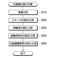
- the assembly work of the compressor 10 includes a preparation process, a fixing process of the stator 21, a centering process of the auxiliary bearing 16a, a fixing process of the auxiliary bearing member 16, and an assembly process of the compression mechanism portion 30 and the like. Includes.
- each component of the compressor 10 is prepared.
- a first housing portion 121 or the like having a first inner peripheral surface 82 and a second inner peripheral surface 83 processed in a state where the coaxiality is accurately matched is prepared.
- the stator 21 of the motor portion 20 is fixed to the first inner peripheral surface 82 of the tubular portion 121b.
- the stator 21 is fixed to the first inner peripheral surface 82 of the first housing portion 121 by shrink fitting.
- the subsequent centering step of the auxiliary bearing 16a in step S30 is a step of aligning the axial center of the auxiliary bearing 16a with the axial center of the second inner peripheral surface 83 of the tubular portion 121b.
- the protrusion 93a of the auxiliary bearing member 16 is fitted into the recessed hole 93b of the bottom portion 121c of the first housing portion 121.
- the outer peripheral surface of the protrusion 93a of the auxiliary bearing member 16 and the inner peripheral surface of the auxiliary bearing 16a are processed in a state where the coaxiality is accurately matched.
- the second inner peripheral surface 83 and the recessed hole 93b of the tubular portion 121b are machined in a state where the coaxiality is accurately matched.
- the clearance between the outer peripheral surface of the protrusion 93a and the inner peripheral surface of the recessed hole 93b is extremely small. Therefore, when the protrusion 93a is fitted into the recessed hole 93b, the deviation of the axis of the inner peripheral surface of the auxiliary bearing 16a with respect to the axis of the second inner peripheral surface 83 of the tubular portion 121b is suppressed.
- the auxiliary bearing member 16 is attached to the first housing portion 121 with the axial center of the auxiliary bearing 16a and the axial center of the second inner peripheral surface 83 of the tubular portion 121b aligned.
- This is a step of fixing to the inner surface of the bottom portion 121c.
- the auxiliary bearing member 16 is fixed to the bottom portion 121c of the first housing portion 121 by the fastening bolt 18.
- step S50 first, the main bearing member 36 is assembled with the drive shaft 14, the main bearing member 36, the swivel scroll 34, and the fixed scroll 32. And the fixed scroll 32 are temporarily assembled by the first bolt 71. In this state, by aligning the main bearing member 36 and the fixed scroll 32, the axial misalignment between the swivel scroll 34 and the fixed scroll 32 is adjusted.
- the compression mechanism portion 30 is assembled to the first housing portion 121.
- the compression mechanism portion 30 is inserted from one side of the axial DRa into the inside of the first housing portion 121.
- the end surface 362b of the main bearing member 36 of the compression mechanism portion 30 is brought into contact with the stepped surface 81 of the first housing portion 121.
- a plurality of second bolts 72 are inserted from one side of the axial DRa toward the other side.
- the compression mechanism portion 30 is fastened and fixed to the housing 12 by a plurality of second bolts 72. Then, after assembling the compression mechanism portion 30 to the first housing portion 121, the second housing portion 122 is fixed to the first housing portion 121. Further, the inverter 25 is fixed to the outer surface of the bottom portion 121c of the first housing portion 121 before or after fixing the second housing portion 122 to the first housing portion 121. The rotor 22 of the motor unit 20 is fixed to the drive shaft 14 in advance by means such as shrink fitting before assembling the compression mechanism unit 30 to the first housing unit 121.
- the compressor 10 described above is applied to a refrigeration cycle device in which a refrigerant containing carbon dioxide as a main component circulates.
- a refrigerant containing carbon dioxide as a main component circulates.
- the difference in high and low pressure in the cycle is large as compared with the case where a Freon-based refrigerant is used. Therefore, since a high load acts on the main bearing 361a, the auxiliary bearing 16a, and the like of the compressor 10, the required level of durability for the compressor 10 is high.
- the eccentric bearing 342a, the main bearing 361a, and the auxiliary bearing 16a are composed of a slide bearing having excellent durability. As a result, even when the difference between high and low pressure in the cycle is large and a high load acts on the bearing, the reliability against wear deterioration is improved and the life can be extended as compared with the rolling bearing.
- each bearing 361a is improved in seizure resistance by suppressing a local increase in surface pressure and from the viewpoint of ensuring wear resistance by forming a good oil film. , It is necessary to align the axes of 16a as much as possible.
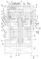
- FIG. 4 is an axial sectional view of the compressor CE1 which is the first comparative example of the present embodiment.
- the auxiliary bearing member 16 is integrally formed on the bottom portion 121c, and the axial alignment gap ⁇ p between the outer peripheral surface 30a of the compression mechanism portion 30 and the second inner peripheral surface 83 of the tubular portion 121b. Is different from the compressor 10 of the present embodiment in that is formed.
- FIG. 4 among the components of the compressor CE1 of the first comparative example, those corresponding to the components of the compressor 10 of the present embodiment are configured, whereas the components of the compressor 10 of the present embodiment are configured. It has the same code as the part.
- the auxiliary bearing member 16 is integrally formed with the bottom portion 121c, and the position of the auxiliary bearing 16a cannot be adjusted with respect to the first housing portion 121. Therefore, the assembly equipment detects the axis of the main bearing 361a while displaced the compression mechanism portion 30 relative to the first housing portion 121, aligns it with the axis of the auxiliary bearing 16a, and adjusts the state. It is necessary to tighten the second bolt 72 while holding it.
- the axial alignment gap ⁇ p of the compressor CE1 of the first comparative example is made extremely small, and the relative bearings 361a and 16a are relative to each other. It is conceivable to improve the dimensional tolerance and shape tolerance that affect the variation in coaxiality with high accuracy. In the compressor CE2 of the second comparative example, it is possible to keep the variation in the coaxiality of each bearing 361a, 16a, etc. within the range that is qualitatively acceptable by simply assembling each component.
- auxiliary bearing member 16 is integrally formed on the bottom portion 121c as in the compressor CE2 of the second comparative example, it is necessary to increase the length of the shaft of the grindstone in order to polish the auxiliary bearing 16a. There is.
- the shaft of the grindstone is lengthened, the degree of difficulty in polishing increases due to the deflection of the shaft or the swing of the grindstone, and it becomes difficult to obtain the required accuracy such as coaxiality, surface roughness, and cylindricity. Then, in order to secure the required accuracy, it is necessary to introduce dedicated equipment that enables high-precision processing, and the investment amount becomes high.
- the auxiliary bearing member 16 is configured separately from the first housing portion 121 and is fixed to the bottom surface of the bottom portion 121c of the first housing portion 121. According to this, since the inner peripheral surface of the auxiliary bearing 16a can be machined with the auxiliary bearing member 16 removed from the housing 12, the inner peripheral surface of the auxiliary bearing 16a can be accurately processed without introducing dedicated equipment. It becomes possible to process. That is, since the auxiliary bearing 16a can be polished in the state of the auxiliary bearing member 16, it is not necessary to lengthen the shaft length of the polishing grindstone, and the polishing accuracy of the auxiliary bearing 16a is high even with relatively inexpensive general-purpose equipment. Accuracy can be ensured.
- the accuracy of the auxiliary bearing 16a that supports the drive shaft 14 on the bottom portion 121c side of the first housing portion 121 without introducing dedicated equipment can be improved. Can be secured. As a result, it is possible to achieve both productivity and high quality while suppressing capital investment.
- Such a compressor 10 is effective for application to a compressor having a high level of durability requirement, such as a refrigeration cycle device in which a refrigerant containing carbon dioxide as a main component is used and a difference in high and low pressure in a cycle is large. Further, the compressor 10 of the present embodiment is effective to be applied to a compressor having a high need for small size, light weight, and low cost, such as an in-vehicle compressor. Further, in the compressor 10 of the present embodiment, for example, like a scroll type compressor, the load support of the drive shaft 14 has a cantilever structure, the drive shaft 14 and the bearing are relatively easy to tilt, and the bearing is locally supported. It is effective to apply it to a structure in which the surface pressure tends to increase.
- the auxiliary bearing member 16 is fixed to the bottom surface of the bottom portion 121c by a fastening bolt 18. According to this, a high fastening force can be obtained with a relatively small number of assembly man-hours.
- the compressor 10 has an auxiliary bearing centering structure that aligns the axial center of the auxiliary bearing 16a with the axial center of the second inner peripheral surface 83 of the tubular portion 121b. According to this, the axial misalignment between the axial center of the auxiliary bearing 16a and the axial center of the second inner peripheral surface 83 of the first housing portion 121 is suppressed.
- the compressor 10 has a main bearing centering structure that aligns the axis of the main bearing 361a with the axis of the second inner peripheral surface 83 of the tubular portion 121b. According to this, the axial deviation between the axial center of the main bearing 361a and the axial center of the second inner peripheral surface 83 of the first housing portion 121 is suppressed.
- the compressor 10 has both a main bearing centering structure and a sub-bearing centering structure, so that the axial center is displaced due to the tolerance stacking between the inner peripheral surface of the main bearing 361a and the inner peripheral surface of the sub-bearing 16a during assembly work. Can be suppressed with high accuracy. As a result, the seizure resistance can be improved by suppressing the local increase in surface pressure of each of the bearings 361a and 16a. Further, each of the bearings 361a and 16a is in a good oil film forming state and the wear resistance is improved, so that the reliability of the bearing can be improved.
- the auxiliary bearing alignment structure is an in-row fitting in which the protrusion 93a formed in the auxiliary bearing member 16 is fitted into the recessed hole 93b formed in the first housing portion 121 to position the auxiliary bearing member 16.
- the recessed hole 93b and the protrusion 93a constituting the inlay fitting structure 93 can be formed with high accuracy by processing using general-purpose equipment such as a lathe. Therefore, the positioning accuracy of the auxiliary bearing member 16 can be ensured without introducing dedicated equipment.
- the main bearing centering structure includes an in-row fitting structure 91 in which the outer periphery of the compression mechanism portion 30 is fitted into the second inner peripheral surface 83 of the first housing portion 121 to position the main bearing member 36.
- the in-row fitting structure 91 can be formed with high accuracy by processing using general-purpose equipment such as a lathe. Therefore, the positioning accuracy of the main bearing member 36 can be ensured without introducing dedicated equipment.
- the main bearing centering structure is formed by fitting a common positioning pin 92c into each of the housing hole 92a formed in the first housing portion 121 and the main bearing side hole 92b formed in the main bearing member 36. It includes a pin fitting structure 92 for positioning 36.
- the positioning pin 92c while suppressing the axial deviation of the axial center of the main bearing 361a with respect to the axial center of the second inner peripheral surface 83 of the first housing portion 121, the positioning pin 92c also positions the main bearing member 36 in the rotational direction. Can be done. Therefore, the assembling property of the main bearing member 36 to the first housing portion 121 can be ensured.
- the positioning pin 92c functions as a detent to prevent the main bearing member 36 from rotating due to the driving force of the motor unit 20. It can prevent the bearing from turning around.
- the tubular portion 121b and the bottom portion 121c of the first housing portion 121 are configured as separate bodies, the meat for forming a bolt seat or the like for fastening the two with bolts. It is necessary to give the thickness to each of the cylinder portion 121b and the bottom portion 121c.
- the first housing portion 121 is configured as an integrally molded product in which the tubular portion 121b and the bottom portion 121c are seamless. According to this, it is not necessary to provide each of the tubular portion 121b and the bottom portion 121c with a wall thickness for forming the bolt seat or the like, and it is possible to obtain the required rigidity with a relatively thin wall thickness. This can reduce the number of parts and secure the pressure resistance while suppressing the weight of the housing 12.
- the main bearing centering structure includes the in-row fitting structure 91 and the pin fitting structure 92, respectively, but the compressor 10 is not limited to this.
- the compressor 10 may have, for example, one of the fitting structure of the in-row fitting structure 91 and the pin fitting structure 92.
- an axial alignment gap ⁇ p is formed between the outer peripheral surface 30a of the compression mechanism portion 30 and the second inner peripheral surface 83 of the first housing portion 121. May be.
- the in-row fitting structure 93 a structure in which the convex portion formed in the auxiliary bearing member 16 is fitted into the concave portion formed in the bottom portion 121c of the first housing portion 121 is exemplified.
- the fitting structure 93 is not limited to this.
- the in-row fitting structure 93 may be, for example, a fitting structure in which a concave portion formed in the auxiliary bearing member 16 is fitted into a convex portion formed in the bottom portion 121c of the first housing portion 121.
- the in-row fitting structure 93 may be adapted to fit the convex portion and the concave portion having a shape other than the circular shape as long as the clearance between the concave portion and the convex portion is closed.
- the auxiliary bearing member 16 is provided with a circular flange portion 162, but the flange portion 162 is not limited to this, and may have a shape other than the circular shape. good.
- the flange portion 162 may have a substantially triangular shape, for example, as shown in FIG. According to this, the area covered by the flange portion 162 on the bottom surface of the bottom portion 121c of the first housing portion 121 can be suppressed. As a result, it becomes easy to avoid the interference between the flange portion 162 and the airtight terminal 121d, and the degree of freedom in the layout of the airtight terminal 121d can be improved.
- the compression mechanism portion 30 is fixed to the first housing portion 121 by the second bolt 72.
- the second bolt 72 may be omitted if the compression mechanism portion 30 is fixed by another means such as being sandwiched between the first housing portion 121 and the second housing portion 122. Further, even if it is not fixed, the second bolt 72 may not necessarily be present. That is, the compression mechanism portion 30 is pressed against the stepped surface 81 between the inner peripheral surfaces 82 and 83 of the first housing portion 121 due to the pressure difference generated during operation, and is substantially fixed during operation by the frictional force generated thereby. If so, the second bolt 72 may not be present. In these cases, even if a rotational force acts from the electric motor unit 20 to the compression mechanism unit 30, the positioning pin 92c of the pin fitting structure 92 receives the rotational force, so that it is possible to prevent misalignment such as turning.
- the pin fitting structure 92 described in the first embodiment is omitted.
- the pin fitting structure 94 constitutes the auxiliary bearing centering structure.
- a common positioning pin 94c is fitted into each of the bottom wall hole 94a formed in the bottom portion 121c of the first housing portion 121 and the auxiliary bearing side hole 94b formed in the auxiliary bearing member 16, and the auxiliary bearing is provided. It is a fitting structure for positioning the member 16.
- the positioning pin 94c is a cylindrical member.
- the bottom wall hole 94a is a bottomed hole having a size into which a positioning pin 94c can be inserted.
- the auxiliary bearing side hole 94b is a bottomed hole or a through hole having a size into which the positioning pin 94c can be inserted.
- a plurality of bottom wall holes 94a and auxiliary bearing side holes 94b are formed at portions facing each other in the bottom portion 121c and the auxiliary bearing member 16. Specifically, a plurality of bottom wall holes 94a are formed in a portion of the bottom surface of the bottom portion 121c facing the flange portion 162.
- a plurality of auxiliary bearing side holes 94b are formed in a portion of the flange portion 162 that is in contact with the bottom surface of the bottom portion 121c.
- the auxiliary bearing alignment structure includes the pin fitting structure 94. According to this, while suppressing the axial deviation of the axial center of the auxiliary bearing 16a with respect to the axial center of the second inner peripheral surface 83 of the first housing portion 121, the positioning pin 94c can also position the auxiliary bearing member 16 in the rotational direction. As a result, the position of the insertion hole 162a of the fastening bolt 18 of the auxiliary bearing member 16 and the screw hole formed in the bottom portion 121c can be easily aligned, so that the auxiliary bearing member 16 can be sufficiently assembled to the first housing portion 121. Can be secured.
- the auxiliary bearing alignment structure is exemplified by the pin fitting structure 94, but the auxiliary bearing alignment structure is not limited to this, for example, the in-row fitting structure 93 and Each of the pin fitting structures 94 may be included.
- the compressor 10 of the present embodiment is not provided with the auxiliary bearing alignment structure. That is, the first housing portion 121 and the auxiliary bearing member 16 are not provided with a configuration corresponding to the in-row fitting structure 93 described in the first embodiment and the pin fitting structure 94 described in the second embodiment.
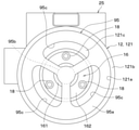
- the compressor 10 uses the centering jig 95 shown in FIGS. 9 and 10 to align the axis of the auxiliary bearing 16a with the axis of the second inner peripheral surface 83 of the tubular portion 121b in the first housing.
- the auxiliary bearing member 16 is fixed to the bottom surface of the bottom portion 121c of the portion 121.
- the centering jig 95 is a dummy shaft that imitates the drive shaft 14.
- the centering jig 95 can be fitted to the inner peripheral surface of the auxiliary bearing 16a and the second inner peripheral surface 83 of the first housing portion 121, respectively.
- the centering jig 95 has a large diameter portion 95a having an outer diameter that can be fitted to the second inner peripheral surface 83 of the tubular portion 121b and a small diameter portion having an outer diameter that can be fitted to the inner peripheral surface of the auxiliary bearing 16a. It has 95b and.
- the centering jig 95 is processed so that the axis of the large diameter portion 95a and the axis of the small diameter portion 95b match with extremely high accuracy.
- the outer diameter of the small diameter portion 95b is smaller than the outer diameter of the large diameter portion 95a.
- the large diameter portion 95a has a substantially cylindrical shape, and the outer diameter thereof is processed so that the clearance with the inner diameter of the second inner peripheral surface 83 of the tubular portion 121b is extremely small.
- a plurality of through holes 95c penetrating in the axial DRa are formed in the large diameter portion 95a.
- the through hole 95c is formed for inserting a bolt tightening jig for fastening the fastening bolt 18.
- the through hole 95c is formed at a position of the large diameter portion 95a of the flange portion 162 facing the insertion hole 162a.
- the small diameter portion 95b has a substantially cylindrical shape, and its outer diameter is processed to a size that makes the clearance with the inner diameter of the auxiliary bearing 16a extremely small.
- the small diameter portion 95b is formed with a tapered portion 95d for guidance that facilitates insertion of the auxiliary bearing 16a into the inside at the tip portion on the opposite side of the connection portion with the large diameter portion 95a.
- each component of the compressor 10 is prepared in the preparation process.
- the stator 21 of the motor unit 20 is fixed to the first inner peripheral surface 82 of the tubular portion 121b by shrink fitting.
- step S30 In the subsequent centering step of the auxiliary bearing 16a in step S30, first, the auxiliary bearing member 16 is temporarily fixed to the bottom surface of the bottom portion 121c by the fastening bolt 18. In this state, the fastening bolt 18 is not tightened to a specified torque, and the auxiliary bearing member 16 can shift its position.
- the centering jig 95 is fitted inside the first housing portion 121. That is, in the centering process, the large diameter portion 95a of the centering jig 95 is fitted into the second inner peripheral surface 83 of the tubular portion 121b, and the small diameter portion 95b of the centering jig 95 is fitted to the inner peripheral surface of the auxiliary bearing 16a. Fit into. At this point, the axial center of the second inner peripheral surface 83 of the tubular portion 121b and the axial center of the inner peripheral surface of the auxiliary bearing 16a are in a state of being suppressed from being displaced.
- step S40 the fastening bolt 18 is tightened with a specified torque to fix the auxiliary bearing member 16 to the bottom surface of the bottom portion 121c.
- a bolt tightening jig is inserted into a through hole 95c formed in the large diameter portion 95a, and the fastening bolt 18 is tightened with a specified torque by the bolt tightening jig.
- step S50 the centering jig 95 is taken out from the inside of the first housing portion 121.
- the drive shaft 14 is assembled to the auxiliary bearing 16a and the compression mechanism portion 30 is assembled to the first housing portion 121.
- the positioning accuracy of the auxiliary bearing member 16 can be ensured by the alignment jig 95 even if the compressor 10 does not have the auxiliary bearing alignment structure. According to this, it is possible to suppress the relative axial deviation between the axial center of the main bearing 361a and the axial center of the auxiliary bearing 16a with high accuracy while suppressing the product cost.
- the stator 21 is fixed to the first housing portion 121.
- the stator 21 in order for the stator 21 not to loosen under the temperature distribution environment under each operating condition of the compressor 10, it is necessary to increase the tightening allowance at the time of shrink fitting.
- the tightening allowance is large, the first housing portion The distortion of 121 becomes large.
- the constituent material of the first housing portion 121 is an aluminum alloy or the like, the temperature of the first housing portion 121 becomes high during shrink fitting, so that distortion is likely to occur due to stress relaxation or the like. These distortions of the first housing portion 121 cause the axial center of the auxiliary bearing 16a to shift.
- the axial alignment of the auxiliary bearing 16a by the centering jig 95 is performed after the fixing step of the stator 21. Therefore, the auxiliary bearing member 16 can be fixed to the bottom surface of the bottom portion 121c in a state where the shaft misalignment due to the distortion of the first housing portion 121 is canceled by the centering jig 95. That is, according to the assembling work of the present embodiment, it is possible to suppress the shaft deviation with higher accuracy.
- the centering jig 95 is not limited to this.
- the centering jig 95 is different from the third embodiment as long as it can align the axial center of the inner peripheral surface of the auxiliary bearing 16a with the axial center of the second inner peripheral surface 83 of the tubular portion 121b. It may be a thing. Further, the centering jig 95 may be configured not as a single unit but as a part of other equipment.
- the auxiliary bearing member 16 is fixed to the bottom surface of the bottom portion 121c by the fastening bolt 18, but the auxiliary bearing member 16 is fixed to the bottom surface of the bottom portion 121c by means other than the fastening bolt 18. May be.
- the compressor 10 is provided with the main bearing alignment structure and the auxiliary bearing alignment structure.
- the main bearing alignment structure and the auxiliary bearing alignment structure are the compressor 10. It is not an essential configuration in the above, and at least one alignment structure may be omitted.
- both the main bearing 361a and the auxiliary bearing 16a are made of a slide bearing, but at least one of the main bearing 361a and the auxiliary bearing 16a is made of a bearing other than the slide bearing. May be.
- the compressor 10 having the scroll type compression mechanism unit 30 is exemplified, but the compressor 10 is not limited to this, and the rotary type compression mechanism unit 30 and the vane type compression mechanism unit 30 are adopted. It may have been done.
- the compressor 10 is not limited to this, and may be used as a temperature control device used in a house, a factory, or the like. On the other hand, it is widely applicable. Further, the compressor 10 is not limited to a horizontal structure in which the motor unit 20 and the compression mechanism unit 30 are arranged in the horizontal direction. For example, the compressor unit 10 has a vertical structure in which the motor unit 20 and the compression mechanism unit 30 are arranged in the vertical DRv. It may be.
- the elements constituting the embodiment are not necessarily essential except when it is clearly stated that they are essential or when they are clearly considered to be essential in principle.
- the shape, positional relationship, etc. of a component or the like when the shape, positional relationship, etc. of a component or the like is referred to, the shape, positional relationship, etc. are not specified unless otherwise specified or limited in principle to a specific shape, positional relationship, etc. Not limited to, etc.
- the compressor comprises a compression mechanism section, a motor section, a drive shaft, and a housing.
- the housing includes a bottomed tubular first housing portion that opens on one side in the axial direction of the drive shaft, and a second housing portion that covers the opening of the first housing portion.
- the drive shaft is rotatably supported by a main bearing whose one side in the axial direction is integrally formed or fixed to the main bearing member, and the other side in the axial direction is integrally formed or integrally formed inside the body of the auxiliary bearing member. It is rotatably supported by a fixed auxiliary bearing.
- the compression mechanism portion including the main bearing member is arranged inside the tubular portion of the first housing portion.
- the auxiliary bearing member is formed separately from the first housing portion and is fixed to the bottom surface of the bottom portion of the first housing portion. According to this, since the inner peripheral surface of the auxiliary bearing can be processed with the auxiliary bearing member removed from the housing, it is possible to accurately process the inner peripheral surface of the auxiliary bearing without introducing special equipment. Will be. That is, since the auxiliary bearing can be polished in the state of the auxiliary bearing member, it is not necessary to lengthen the shaft length of the polishing grindstone, and the auxiliary bearing polishing accuracy is ensured even with relatively inexpensive general-purpose equipment. can do.
- the auxiliary bearing member is fixed to the bottom surface of the bottom portion by a fastening bolt. According to this, a high fastening force can be obtained with a relatively small number of assembly man-hours.
- the compressor is provided with an auxiliary bearing centering structure that aligns the axial center of the auxiliary bearing with the axial center of the inner peripheral surface of the insertion portion where the compression mechanism portion is inserted in the tubular portion.
- an auxiliary bearing centering structure that aligns the axial center of the auxiliary bearing with the axial center of the inner peripheral surface of the insertion portion where the compression mechanism portion is inserted in the tubular portion.
- the convex portion formed on the other side of the first housing portion and the auxiliary bearing member is fitted into the concave portion formed on one of the first housing portion and the auxiliary bearing member.
- a fitting structure that positions the sub-bearing member in.
- the convex portions and concave portions constituting the fitting structure can be formed with high accuracy by processing using general-purpose equipment such as a lathe. Therefore, since the positioning accuracy of the auxiliary bearing member can be ensured without introducing dedicated equipment, it is possible to suppress the accumulation variation of the relative axial deviation amount of the axial center of each bearing.
- a common positioning pin is fitted into each of the bottom wall hole formed in the bottom portion and the auxiliary bearing side hole formed in the auxiliary bearing member to form the auxiliary bearing member.
- the auxiliary bearing member can be positioned in the rotational direction by the positioning pin, so that the auxiliary bearing portion can be positioned. Sufficient assembling property of the bearing member can be ensured.
- the sub-bearing member is subordinated by a centering jig that can be fitted to each of the inner peripheral surface of the sub-bearing and the inner peripheral surface of the insertion portion where the compression mechanism portion is inserted among the tubular portion. It is fixed to the bottom surface of the bottom part with the axis of the bearing aligned with the axis of the insertion site.
- the positioning accuracy of the auxiliary bearing member can be ensured without adding the auxiliary bearing alignment structure to the compressor, the accumulation variation of the relative axial deviation amount of the axial center of each bearing can be ensured. Can be suppressed.
- the compressor is provided with a main bearing centering structure that aligns the axial center of the main bearing with the axial center of the inner peripheral surface of the insertion portion where the compression mechanism portion is inserted in the tubular portion. According to this, it is possible to suppress the accumulation variation of the relative axial deviation amount of the axial center of each bearing. As a result, it is possible to suppress a local increase in surface pressure and ensure good oil film formation in each bearing, and it is possible to secure the reliability of each bearing.
- the main bearing centering structure includes a fitting structure in which the outer peripheral surface of the compression mechanism portion is fitted to the inner peripheral surface of the insertion portion to position the main bearing member.
- a fitting structure can be formed with high accuracy by processing using general-purpose equipment such as a lathe. Therefore, since the positioning accuracy of the main bearing member can be ensured without introducing dedicated equipment, it is possible to suppress the accumulation variation of the relative axial deviation amount of the axial center of each bearing.
- the main bearing centering structure is formed by fitting a common positioning pin into each of the housing hole formed in the first housing portion and the main bearing side hole formed in the main bearing member. Includes a pin fitting structure for positioning.
- the positioning pin can also position the main bearing member in the rotational direction, so that the main bearing with respect to the first housing portion can be positioned. Sufficient assembling property of the member can be ensured.
- the positioning pin functions as a detent to prevent the main bearing member from rotating due to the driving force of the motor unit.
- At least one of the main bearing and the auxiliary bearing is composed of a plain bearing. According to this, it is possible to secure the reliability against wear deterioration and extend the life while ensuring the seizure resistance of the bearing of the drive shaft.
- the compression mechanism portion includes a fixed scroll fixed to the first housing portion and a swivel scroll that compresses the fluid by engaging with the fixed scroll when swiveling due to the rotation of the drive shaft. ..
- the scroll type compression mechanism portion having less torque fluctuation, the load of each bearing is suppressed, so that the seizure resistance and wear resistance of the bearing can be ensured.
- the axial center of the auxiliary bearing and the axial center of the inner peripheral surface of the insertion portion where the compression mechanism portion is inserted in the cylindrical portion are aligned with each other.
- the bearing member is fixed to the inner surface of the bottom of the first housing portion.
- the axial center of the auxiliary bearing and the inside of the insertion portion are fitted. Align with the axis of the peripheral surface. According to this, since the positioning accuracy of the auxiliary bearing member can be ensured without adding the auxiliary bearing alignment structure to the compressor, the relative of the axial center of the main bearing and the axial center of the auxiliary bearing. It is possible to suppress the misalignment of the axis with high accuracy.
Landscapes
- Engineering & Computer Science (AREA)
- Mechanical Engineering (AREA)
- General Engineering & Computer Science (AREA)
- Applications Or Details Of Rotary Compressors (AREA)
- Rotary Pumps (AREA)
Priority Applications (3)
| Application Number | Priority Date | Filing Date | Title |
|---|---|---|---|
| CN202180058063.0A CN116097001B (zh) | 2020-08-05 | 2021-07-09 | 压缩机、压缩机的制造方法 |
| DE112021004193.2T DE112021004193T5 (de) | 2020-08-05 | 2021-07-09 | Verdichter und Verfahren zum Herstellen eines Verdichters |
| US18/157,261 US12078168B2 (en) | 2020-08-05 | 2023-01-20 | Compressor and method for manufacturing compressor |
Applications Claiming Priority (2)
| Application Number | Priority Date | Filing Date | Title |
|---|---|---|---|
| JP2020133286A JP7439690B2 (ja) | 2020-08-05 | 2020-08-05 | 圧縮機、圧縮機の製造方法 |
| JP2020-133286 | 2020-08-05 |
Related Child Applications (1)
| Application Number | Title | Priority Date | Filing Date |
|---|---|---|---|
| US18/157,261 Continuation US12078168B2 (en) | 2020-08-05 | 2023-01-20 | Compressor and method for manufacturing compressor |
Publications (1)
| Publication Number | Publication Date |
|---|---|
| WO2022030185A1 true WO2022030185A1 (ja) | 2022-02-10 |
Family
ID=80117921
Family Applications (1)
| Application Number | Title | Priority Date | Filing Date |
|---|---|---|---|
| PCT/JP2021/026024 Ceased WO2022030185A1 (ja) | 2020-08-05 | 2021-07-09 | 圧縮機、圧縮機の製造方法 |
Country Status (5)
| Country | Link |
|---|---|
| US (1) | US12078168B2 (https=) |
| JP (1) | JP7439690B2 (https=) |
| CN (1) | CN116097001B (https=) |
| DE (1) | DE112021004193T5 (https=) |
| WO (1) | WO2022030185A1 (https=) |
Cited By (2)
| Publication number | Priority date | Publication date | Assignee | Title |
|---|---|---|---|---|
| EP4336043A3 (de) * | 2022-08-16 | 2024-04-03 | BITZER Kühlmaschinenbau GmbH | Scrollmaschine und kälteanlage |
| WO2024125800A1 (de) * | 2022-12-15 | 2024-06-20 | Pierburg Gmbh | Spiralverdichter |
Families Citing this family (1)
| Publication number | Priority date | Publication date | Assignee | Title |
|---|---|---|---|---|
| DE102024201453A1 (de) * | 2024-02-16 | 2025-08-21 | Brose Fahrzeugteile SE & Co. Kommanditgesellschaft, Würzburg | Scrollmaschine |
Citations (5)
| Publication number | Priority date | Publication date | Assignee | Title |
|---|---|---|---|---|
| JPS62186084A (ja) * | 1986-02-12 | 1987-08-14 | Mitsubishi Electric Corp | スクロ−ル圧縮機 |
| JPH04143476A (ja) * | 1990-10-05 | 1992-05-18 | Mitsubishi Electric Corp | スクロール圧縮機の製造方法 |
| US6247909B1 (en) * | 1999-08-18 | 2001-06-19 | Scroll Technologies | Bearing assembly for sealed compressor |
| JP2019183832A (ja) * | 2018-03-30 | 2019-10-24 | 株式会社豊田自動織機 | スクロール型圧縮機 |
| JP2020020291A (ja) * | 2018-07-31 | 2020-02-06 | 株式会社デンソー | 圧縮機 |
Family Cites Families (9)
| Publication number | Priority date | Publication date | Assignee | Title |
|---|---|---|---|---|
| CA2042203C (en) * | 1990-07-24 | 1996-02-13 | Hiroaki Kondo | Scroll type fluid machinery |
| US6280155B1 (en) * | 2000-03-21 | 2001-08-28 | Tecumseh Products Company | Discharge manifold and mounting system for, and method of assembling, a hermetic compressor |
| US8147229B2 (en) * | 2005-01-20 | 2012-04-03 | Tecumseh Products Company | Motor-compressor unit mounting arrangement for compressors |
| CN100510415C (zh) * | 2007-12-12 | 2009-07-08 | 李东林 | 滑片与气缸共同圆心式旋转压缩机 |
| JP2009228441A (ja) * | 2008-03-19 | 2009-10-08 | Sanyo Electric Co Ltd | スクロール圧縮機 |
| JP6225626B2 (ja) | 2013-10-09 | 2017-11-08 | 株式会社デンソー | フィルタユニット |
| DE102019108079B4 (de) | 2018-03-30 | 2023-08-31 | Kabushiki Kaisha Toyota Jidoshokki | Schneckenverdichter |
| CN209012052U (zh) * | 2018-08-20 | 2019-06-21 | 江森自控日立万宝压缩机(广州)有限公司 | 一种涡旋压缩机的油泵与曲轴下支承安装结构 |
| JP7180443B2 (ja) | 2019-02-21 | 2022-11-30 | コベルコ建機株式会社 | 作業機械 |
-
2020
- 2020-08-05 JP JP2020133286A patent/JP7439690B2/ja active Active
-
2021
- 2021-07-09 CN CN202180058063.0A patent/CN116097001B/zh active Active
- 2021-07-09 WO PCT/JP2021/026024 patent/WO2022030185A1/ja not_active Ceased
- 2021-07-09 DE DE112021004193.2T patent/DE112021004193T5/de active Pending
-
2023
- 2023-01-20 US US18/157,261 patent/US12078168B2/en active Active
Patent Citations (5)
| Publication number | Priority date | Publication date | Assignee | Title |
|---|---|---|---|---|
| JPS62186084A (ja) * | 1986-02-12 | 1987-08-14 | Mitsubishi Electric Corp | スクロ−ル圧縮機 |
| JPH04143476A (ja) * | 1990-10-05 | 1992-05-18 | Mitsubishi Electric Corp | スクロール圧縮機の製造方法 |
| US6247909B1 (en) * | 1999-08-18 | 2001-06-19 | Scroll Technologies | Bearing assembly for sealed compressor |
| JP2019183832A (ja) * | 2018-03-30 | 2019-10-24 | 株式会社豊田自動織機 | スクロール型圧縮機 |
| JP2020020291A (ja) * | 2018-07-31 | 2020-02-06 | 株式会社デンソー | 圧縮機 |
Cited By (3)
| Publication number | Priority date | Publication date | Assignee | Title |
|---|---|---|---|---|
| EP4336043A3 (de) * | 2022-08-16 | 2024-04-03 | BITZER Kühlmaschinenbau GmbH | Scrollmaschine und kälteanlage |
| US12331743B2 (en) | 2022-08-16 | 2025-06-17 | Bitzer Kühlmaschinenbau Gmbh | Scroll machine with multiple flow paths for the inlet flow including in the hollow shaft portion |
| WO2024125800A1 (de) * | 2022-12-15 | 2024-06-20 | Pierburg Gmbh | Spiralverdichter |
Also Published As
| Publication number | Publication date |
|---|---|
| JP2022029784A (ja) | 2022-02-18 |
| US20230151813A1 (en) | 2023-05-18 |
| CN116097001B (zh) | 2024-06-28 |
| US12078168B2 (en) | 2024-09-03 |
| CN116097001A (zh) | 2023-05-09 |
| DE112021004193T5 (de) | 2023-06-29 |
| JP7439690B2 (ja) | 2024-02-28 |
Similar Documents
| Publication | Publication Date | Title |
|---|---|---|
| WO2022030185A1 (ja) | 圧縮機、圧縮機の製造方法 | |
| JPH0472486A (ja) | スクロール圧縮機 | |
| JP5998012B2 (ja) | スクロール式流体機械 | |
| WO2014155546A1 (ja) | スクロール圧縮機 | |
| US11028848B2 (en) | Scroll compressor having a fitted bushing and weight arrangement | |
| EP2236829B1 (en) | Sealed-type scroll compressor | |
| JP7119721B2 (ja) | 圧縮機 | |
| JP3858762B2 (ja) | スライドブッシュ及びスクロール型流体機械 | |
| US20250305501A1 (en) | Scroll compressor | |
| WO2018131235A1 (ja) | スクロール式圧縮機 | |
| JP4939239B2 (ja) | クランクシャフト | |
| JP2014227919A (ja) | 圧縮機 | |
| JP2008008161A (ja) | 圧縮機 | |
| CN118043558A (zh) | 涡旋压缩机及其制造方法 | |
| JP4415178B2 (ja) | スクロール流体機械及びその組立方法 | |
| JP6673099B2 (ja) | 圧縮機、および圧縮機の製造方法 | |
| JP5430208B2 (ja) | 密閉型流体機械 | |
| US20250101976A1 (en) | Scroll compressor | |
| WO2024085064A1 (ja) | 電動圧縮機 | |
| JP3858580B2 (ja) | 密閉型電動圧縮機 | |
| JPH09177687A (ja) | 電動式流体機械 | |
| JP2023077785A (ja) | 電動圧縮機及び製造方法 | |
| CN119373707A (zh) | 电动压缩机 | |
| JP2010031794A (ja) | スクロール式流体機械 | |
| JP2001050180A (ja) | スクロ−ル圧縮機 |
Legal Events
| Date | Code | Title | Description |
|---|---|---|---|
| 121 | Ep: the epo has been informed by wipo that ep was designated in this application |
Ref document number: 21854286 Country of ref document: EP Kind code of ref document: A1 |
|
| 122 | Ep: pct application non-entry in european phase |
Ref document number: 21854286 Country of ref document: EP Kind code of ref document: A1 |