WO2022030185A1 - Compressor and method for manufacturing compressor - Google Patents
Compressor and method for manufacturing compressor Download PDFInfo
- Publication number
- WO2022030185A1 WO2022030185A1 PCT/JP2021/026024 JP2021026024W WO2022030185A1 WO 2022030185 A1 WO2022030185 A1 WO 2022030185A1 JP 2021026024 W JP2021026024 W JP 2021026024W WO 2022030185 A1 WO2022030185 A1 WO 2022030185A1
- Authority
- WO
- WIPO (PCT)
- Prior art keywords
- auxiliary bearing
- bearing member
- housing
- compression mechanism
- peripheral surface
- Prior art date
Links
Images


Classifications
-
- F—MECHANICAL ENGINEERING; LIGHTING; HEATING; WEAPONS; BLASTING
- F04—POSITIVE - DISPLACEMENT MACHINES FOR LIQUIDS; PUMPS FOR LIQUIDS OR ELASTIC FLUIDS
- F04C—ROTARY-PISTON, OR OSCILLATING-PISTON, POSITIVE-DISPLACEMENT MACHINES FOR LIQUIDS; ROTARY-PISTON, OR OSCILLATING-PISTON, POSITIVE-DISPLACEMENT PUMPS
- F04C18/00—Rotary-piston pumps specially adapted for elastic fluids
- F04C18/02—Rotary-piston pumps specially adapted for elastic fluids of arcuate-engagement type, i.e. with circular translatory movement of co-operating members, each member having the same number of teeth or tooth-equivalents
- F04C18/0207—Rotary-piston pumps specially adapted for elastic fluids of arcuate-engagement type, i.e. with circular translatory movement of co-operating members, each member having the same number of teeth or tooth-equivalents both members having co-operating elements in spiral form
- F04C18/0215—Rotary-piston pumps specially adapted for elastic fluids of arcuate-engagement type, i.e. with circular translatory movement of co-operating members, each member having the same number of teeth or tooth-equivalents both members having co-operating elements in spiral form where only one member is moving
-
- F—MECHANICAL ENGINEERING; LIGHTING; HEATING; WEAPONS; BLASTING
- F04—POSITIVE - DISPLACEMENT MACHINES FOR LIQUIDS; PUMPS FOR LIQUIDS OR ELASTIC FLUIDS
- F04C—ROTARY-PISTON, OR OSCILLATING-PISTON, POSITIVE-DISPLACEMENT MACHINES FOR LIQUIDS; ROTARY-PISTON, OR OSCILLATING-PISTON, POSITIVE-DISPLACEMENT PUMPS
- F04C23/00—Combinations of two or more pumps, each being of rotary-piston or oscillating-piston type, specially adapted for elastic fluids; Pumping installations specially adapted for elastic fluids; Multi-stage pumps specially adapted for elastic fluids
- F04C23/008—Hermetic pumps
-
- F—MECHANICAL ENGINEERING; LIGHTING; HEATING; WEAPONS; BLASTING
- F04—POSITIVE - DISPLACEMENT MACHINES FOR LIQUIDS; PUMPS FOR LIQUIDS OR ELASTIC FLUIDS
- F04C—ROTARY-PISTON, OR OSCILLATING-PISTON, POSITIVE-DISPLACEMENT MACHINES FOR LIQUIDS; ROTARY-PISTON, OR OSCILLATING-PISTON, POSITIVE-DISPLACEMENT PUMPS
- F04C29/00—Component parts, details or accessories of pumps or pumping installations, not provided for in groups F04C18/00 - F04C28/00
- F04C29/0042—Driving elements, brakes, couplings, transmissions specially adapted for pumps
- F04C29/005—Means for transmitting movement from the prime mover to driven parts of the pump, e.g. clutches, couplings, transmissions
-
- F—MECHANICAL ENGINEERING; LIGHTING; HEATING; WEAPONS; BLASTING
- F04—POSITIVE - DISPLACEMENT MACHINES FOR LIQUIDS; PUMPS FOR LIQUIDS OR ELASTIC FLUIDS
- F04C—ROTARY-PISTON, OR OSCILLATING-PISTON, POSITIVE-DISPLACEMENT MACHINES FOR LIQUIDS; ROTARY-PISTON, OR OSCILLATING-PISTON, POSITIVE-DISPLACEMENT PUMPS
- F04C2230/00—Manufacture
- F04C2230/60—Assembly methods
- F04C2230/603—Centering; Aligning
-
- F—MECHANICAL ENGINEERING; LIGHTING; HEATING; WEAPONS; BLASTING
- F04—POSITIVE - DISPLACEMENT MACHINES FOR LIQUIDS; PUMPS FOR LIQUIDS OR ELASTIC FLUIDS
- F04C—ROTARY-PISTON, OR OSCILLATING-PISTON, POSITIVE-DISPLACEMENT MACHINES FOR LIQUIDS; ROTARY-PISTON, OR OSCILLATING-PISTON, POSITIVE-DISPLACEMENT PUMPS
- F04C2240/00—Components
- F04C2240/30—Casings or housings
-
- F—MECHANICAL ENGINEERING; LIGHTING; HEATING; WEAPONS; BLASTING
- F04—POSITIVE - DISPLACEMENT MACHINES FOR LIQUIDS; PUMPS FOR LIQUIDS OR ELASTIC FLUIDS
- F04C—ROTARY-PISTON, OR OSCILLATING-PISTON, POSITIVE-DISPLACEMENT MACHINES FOR LIQUIDS; ROTARY-PISTON, OR OSCILLATING-PISTON, POSITIVE-DISPLACEMENT PUMPS
- F04C2240/00—Components
- F04C2240/50—Bearings
- F04C2240/52—Bearings for assemblies with supports on both sides
-
- F—MECHANICAL ENGINEERING; LIGHTING; HEATING; WEAPONS; BLASTING
- F04—POSITIVE - DISPLACEMENT MACHINES FOR LIQUIDS; PUMPS FOR LIQUIDS OR ELASTIC FLUIDS
- F04C—ROTARY-PISTON, OR OSCILLATING-PISTON, POSITIVE-DISPLACEMENT MACHINES FOR LIQUIDS; ROTARY-PISTON, OR OSCILLATING-PISTON, POSITIVE-DISPLACEMENT PUMPS
- F04C2240/00—Components
- F04C2240/60—Shafts
Definitions
- the present disclosure relates to a compressor that compresses and discharges the sucked fluid and a method for manufacturing the compressor.
- Patent Document 1 discloses a scroll type compressor.
- This compressor includes a compression mechanism unit, an electric motor unit, a drive shaft for transmitting a driving force output by the electric motor unit to the compression mechanism unit, and a housing for accommodating the compression mechanism unit and the like.
- One side of the drive shaft in the axial direction is rotatably supported by a main bearing formed in a main bearing member forming a part of the compression mechanism portion, and the other side in the axial direction is a tubular body portion of the auxiliary bearing member. It is rotatably supported by an auxiliary bearing formed inside the.
- the housing includes a bottomed tubular housing body portion in which one side in the axial direction of the drive shaft opens, and an auxiliary bearing member is integrally formed with the bottom surface of the bottom portion of the housing body portion.
- a centering gap for aligning the axis of the main bearing and the axis of the sub-bearing is formed between the compression mechanism portion and the inner peripheral surface of the tubular portion of the housing main body portion.
- the axis of the main bearing is detected while the compression mechanism portion is displaced relative to the inner peripheral surface of the tubular portion of the housing main body, and the spindle center is detected. Align the axis of the sub-bearing with the axis of the auxiliary bearing, and fix it to the housing body while maintaining that state.
- the present inventors reduce the gap between the compression mechanism portion and the housing main body portion, and at the same time, coaxialize the axial center of the insertion portion into which the compression mechanism portion of the housing main body portion is inserted with the axial center of the auxiliary bearing.
- the insertion portion of the compression mechanism portion and the inner peripheral surface of the auxiliary bearing of the housing main body are each processed with high accuracy. There is a need to.
- the purpose of the present disclosure is to ensure the accuracy of the bearing that supports the drive shaft on the bottom portion side of the housing portion in the compressor having the bottomed tubular housing portion without introducing dedicated equipment.
- the compressor is The compression mechanism (30) that compresses the fluid,
- the motor unit (20) that outputs the driving force that drives the compression mechanism unit, and
- a drive shaft (14) that transmits the driving force output by the motor unit to the compression mechanism unit
- a housing (12) for accommodating a compression mechanism unit, a motor unit unit, and a drive shaft is provided.
- the housing includes a bottomed tubular first housing portion (121) that opens on one side in the axial direction of the drive shaft, and a second housing portion (122) that covers the opening of the first housing portion.
- One side of the drive shaft in the axial direction is rotatably supported by a main bearing (361a) integrally formed or fixed to a main bearing member (36) that constitutes a part of the compression mechanism.
- the other side of the drive shaft in the axial direction can be rotated by an auxiliary bearing (16a) integrally formed or fixed to the inside of the auxiliary bearing member (16) including a tubular body portion (161).
- the compression mechanism portion including the main bearing member is arranged inside the cylindrical portion (121b) of the first housing portion.
- the auxiliary bearing member is formed separately from the first housing portion and is fixed to the bottom surface of the bottom portion (121c) of the first housing portion.
- the auxiliary bearing member including the auxiliary bearing is configured separately from the first housing portion, the inner peripheral surface of the auxiliary bearing can be machined with the auxiliary bearing member removed from the housing. It is possible to accurately process the inner peripheral surface of the auxiliary bearing without introducing dedicated equipment.
- the compression mechanism (30) that compresses the fluid
- the motor unit (20) that outputs the driving force that drives the compression mechanism unit
- a drive shaft (14) that transmits the driving force output by the motor unit to the compression mechanism unit
- a housing (12) for accommodating a compression mechanism unit, a motor unit unit, and a drive shaft is provided.
- the housing includes a bottomed tubular first housing portion (121) that opens on one side in the axial direction of the drive shaft, and a second housing portion (122) that covers the opening of the first housing portion.
- One side of the drive shaft in the axial direction is rotatably supported by a main bearing (361a) integrally formed or fixed to a main bearing member (36) that constitutes a part of the compression mechanism.
- the other side of the drive shaft in the axial direction can be rotated by an auxiliary bearing (16a) integrally formed or fixed to the inside of the auxiliary bearing member (16) including a tubular body portion (161).
- the compression mechanism portion including the main bearing member is arranged inside the cylindrical portion (121b) of the first housing portion.
- the auxiliary bearing member is a method for manufacturing a compressor that is configured separately from the first housing portion.
- Aligning the axis of the auxiliary bearing with the axis of the inner peripheral surface of the insertion site where the compression mechanism is inserted out of the tubular part It includes fixing the auxiliary bearing member to the inner surface of the bottom portion of the first housing portion in a state where the axial center of the auxiliary bearing and the axial center of the inner peripheral surface of the insertion portion are aligned.
- the inner peripheral surface of the auxiliary bearing of the auxiliary bearing member can be processed before it is attached to the first housing portion, the inner peripheral surface of the auxiliary bearing can be accurately processed without introducing dedicated equipment. It becomes possible to do.
- the refrigeration cycle device constitutes a steam compression type refrigeration cycle.
- the refrigeration cycle device is decompressed by a compressor 10 that compresses and discharges a refrigerant as a fluid, a radiator that dissipates the refrigerant discharged from the compressor 10, a decompression device that decompresses the refrigerant that flows out of the radiator, and a decompression device. It contains an evaporator that evaporates the refrigerant.
- the main component of the refrigerant used in the refrigeration cycle device is carbon dioxide. Carbon dioxide becomes a supercritical state at a lower temperature than Freon-based refrigerants.
- the refrigerant is mixed with lubricating oil that lubricates each sliding portion inside the compressor 10. Part of the lubricating oil circulates in the cycle together with the refrigerant.
- the refrigerant may be a fluorocarbon-based refrigerant.
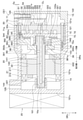
- FIG. 1 is an axial cross-sectional view showing a cross section cut along the axial center CL of the drive shaft 14 of the compressor 10.
- the vertical arrows in FIG. 1 indicate the vertical DRv when the compressor 10 is mounted on the vehicle.
- the arrow “DRa” in FIG. 1 indicates the axial DRa of the drive shaft 14.
- the compressor 10 includes a housing 12, a drive shaft 14, an electric motor unit 20, an inverter 25, and a compression mechanism unit 30.
- a drive shaft 14, an electric motor unit 20, and a compression mechanism unit 30 are housed inside the housing 12.
- the compressor 10 is an electric compressor.
- the drive shaft 14 rotates with the electric motor unit 20 as a power source.
- the compression mechanism unit 30 is driven as the drive shaft 14 rotates.
- the compressor 10 has a horizontal structure in which the axial center CL of the drive shaft 14 extends in a substantially horizontal direction, and the compression mechanism unit 30 and the motor unit 20 are arranged side by side in a substantially horizontal direction.
- the substantially horizontal direction is a direction that intersects the direction of gravity.
- the housing 12 constitutes the outer shell of the compressor 10.
- the housing 12 has a first housing portion 121 and a second housing portion 122.
- the first housing portion 121 and the second housing portion 122 are made of aluminum or an aluminum alloy.
- the first housing portion 121 has a bottomed cylinder shape in which one side of the drive shaft 14 in the axial direction DRa opens.
- the first housing portion 121 has a cup-shaped shape having a U-shaped cross section.
- the first housing portion 121 has a cylindrical tubular portion 121b and a bottom portion 121c.
- the tubular portion 121b has an opening 121a on one side of the axial DRa.
- the bottom portion 121c is connected to the other end of the axial DRa in the tubular portion 121b.
- the first housing portion 121 is configured as an integrally molded product in which the tubular portion 121b and the bottom portion 121c are seamlessly molded. A part of the outer surface of the bottom portion 121c is flat so that the inverter 25 can be brought into close contact with the bottom portion 121c.
- the first housing portion 121 has a stepped shape in which a step portion 80 is formed on the tubular portion 121b. That is, the first housing portion 121 has a first inner peripheral surface 82, a second inner peripheral surface 83, and a stepped surface 81. The distances of the first inner peripheral surface 82, the stepped surface 81, and the second inner peripheral surface 83 from the bottom portion 121c are reduced in this order. In other words, the distances of the first inner peripheral surface 82, the stepped surface 81, and the second inner peripheral surface 83 from the opening 121a increase in this order.
- the first inner peripheral surface 82 and the second inner peripheral surface 83 are formed in a cylindrical shape so as to be concentric circles about the axial center CL of the drive shaft 14.
- the first inner peripheral surface 82 is a portion of the first housing portion 121 where the motor portion 20 is arranged.
- the first inner peripheral surface 82 has a cylindrical shape.
- the second inner peripheral surface 83 is located on one side of the axial DRa with respect to the first inner peripheral surface 82.
- the second inner peripheral surface 83 has a cylindrical shape.
- the second inner peripheral surface 83 is the inner peripheral surface of the insertion portion of the first housing portion 121 into which the compression mechanism portion 30 is inserted.
- the outer diameter of the compression mechanism portion 30 is larger than the outer diameter of the motor portion 20. Therefore, the diameter of the second inner peripheral surface 83 is larger than the diameter of the first inner peripheral surface 82.
- the step surface 81 connects the first inner peripheral surface 82 and the second inner peripheral surface 83.
- the step surface 81 extends in a direction orthogonal to the axial DRa.
- the step surface 81 is in direct contact with the bearing fixing portion 362 of the main bearing member 36 described later.
- the stepped surface 81 may be in contact with the bearing fixing portion 362 via an inclusion.
- the insertion portion of the tubular portion 121b into which the compression mechanism portion 30 is inserted is a portion of the tubular portion 121b located on one side (that is, the opening 121a side) of the axial DRa with respect to the stepped surface 81.
- the compression mechanism portion 30 including the main bearing member 36 is arranged on the inner peripheral surface of the tubular portion 121b, and the auxiliary bearing member 16 including the tubular body portion 161 is fixed to the bottom portion 121c.
- the cylindrical portion 121b constitutes the tubular portion of the first housing portion 121
- the bottom portion 121c constitutes the bottom portion of the first housing portion 121.
- the second housing portion 122 covers the opening of the first housing portion 121 at a position on one side of the axial DRa with respect to the first housing portion 121.
- the second housing portion 122 is fastened and fixed to the first housing portion 121 by a lid bolt (not shown).
- a seal member (not shown) is interposed between one end of the first housing portion 121 in the axial direction DRa and the second housing portion 122. As a result, the housing 12 is hermetically sealed.
- the motor unit 20 is composed of a three-phase AC motor driven by power supply from the inverter 25.
- the electric motor unit 20 is configured as an inner rotor motor in which the rotor 22 is arranged inside the stator 21.
- the stator 21 has a stator core 211 made of a magnetic material and a coil 212 wound around the stator core 211.
- the stator 21 When power is supplied from the inverter 25, the stator 21 generates a rotating magnetic field that rotates the rotor 22.
- the stator 21 is fixed to the first inner peripheral surface 82 of the tubular portion 121b by shrink fitting.
- the rotor 22 is a cylindrical member in which the drive shaft 14 is fixed to the inside by press fitting or the like.
- a permanent magnet (not shown) is arranged inside the rotor 22.
- balance weights 221 and 222 for canceling the imbalance of eccentric rotation such as the swivel scroll 34 are attached to the side surface of the rotor 22.
- the inverter 25 is a device that supplies electric power to the stator 21.
- the inverter 25 is attached to the outside of the housing 12. Specifically, the inverter 25 is attached to the outer surface of the bottom portion 121c of the first housing portion 121.
- the motor unit 20 configured in this way, when electric power is supplied from the inverter 25 to the stator 21 and a rotating magnetic field is generated around the stator 21, the rotor 22 and the drive shaft 14 rotate integrally.
- the inverter 25 and the motor unit 20 are electrically connected to each other via an airtight terminal (not shown) provided on the bottom portion 121c of the first housing unit 121, such as electrical wiring (not shown). Therefore, the housing 12 has a closed structure.
- the first housing portion 121 of the housing 12 is formed with a suction port 125 for sucking the low-pressure refrigerant that has passed through the evaporator.
- the suction port 125 is formed on the other side of the first housing portion 121 in the axial direction DRa with respect to the motor portion 20.
- a suction pipe (not shown) connected to the evaporator is connected to the suction port 125.
- the low-pressure refrigerant that has passed through the evaporator is sucked into the inside of the housing 12 in which the motor unit 20 is arranged from the suction port 125.
- the low-pressure refrigerant sucked into the inside of the housing 12 is sucked into the inside of the compression mechanism portion 30 from a suction port (not shown) of the compression mechanism portion 30. Therefore, the inside of the housing 12 in which the motor unit 20 is arranged has a low temperature atmosphere. As a result, the motor unit 20 and the inverter 25 can be cooled.
- the inverter 25 is attached to a flat portion of the bottom 121c, even if the inverter 25 generates heat during operation, the heat can be efficiently conducted to the bottom 121c to cool the inverter 25. .. Therefore, it is possible to improve the efficiency and reliability of the motor unit 20 and the inverter 25.
- the second housing portion 122 of the housing 12 is formed with a discharge port 126 for discharging the high-pressure refrigerant compressed by the compression mechanism portion 30.
- the discharge port 126 is formed on one side of the housing 12 in the axial direction DRa with respect to the compression mechanism portion 30.
- a high-pressure muffler chamber 51 communicates with the discharge hole 323.
- the high-pressure muffler chamber 51 is a space for reducing the discharge pulsation of the refrigerant discharged from the discharge hole 323.
- the oil separation chamber 52 communicates with the high pressure muffler chamber 51.
- the oil separation chamber 52 is a space for separating lubricating oil from the high-pressure refrigerant flowing in from the high-pressure muffler chamber 51.
- the oil separation chamber 52 contains an oil separator 54 that separates lubricating oil from the high-pressure refrigerant that has flowed into the oil separation chamber 52.
- the oil separator 54 has a pipe shape.
- the oil separator 54 is fixed to the discharge port 126 by press fitting or the like.
- the high-pressure oil storage chamber 53 is a space for storing the lubricating oil separated by the oil separator 54.
- the drive shaft 14 has a one-sided portion 141 located on one side of the axial DRa with respect to the rotor 22.
- the compression mechanism unit 30 is located on one side of the drive shaft 14 in the axial direction DRa with respect to the motor unit 20.
- the one side portion 141 is engaged with the compression mechanism portion 30.
- the drive shaft 14 transmits the driving force generated by the motor unit 20 to the compression mechanism unit 30.
- the one-side portion 141 is rotatably supported by the main bearing 361a included in the main bearing member 36 of the compression mechanism portion 30, which will be described later.
- the one-sided portion 141 has an eccentric shaft portion 142 eccentric from the rotation center of the drive shaft 14 at one end of the axial DRa.
- the eccentric shaft portion 142 constitutes a crank mechanism for the turning motion of the turning scroll 34, which will be described later.
- the eccentric shaft portion 142 is rotatably engaged with the eccentric bearing 342a of the swivel scroll 34 described later.
- the eccentric shaft portion 142 is integrated with the main body of the drive shaft 14.
- the one-side portion 141 has a flange portion 143 that extends in the vertical DRv.
- the flange portion 143 is provided with a balance weight 143a for suppressing the eccentric rotation of the drive shaft 14.
- the drive shaft 14 has a portion 144 on the other side located on the other side of the axial DRa with respect to the rotor 22.
- the other side portion 144 is rotatably supported by the auxiliary bearing 16a included in the auxiliary bearing member 16. Details of the auxiliary bearing member 16 will be described later.
- an oil supply path 145 for supplying lubricating oil to the bearings 16a, 342a, and 361a is formed inside the drive shaft 14.
- the oil supply path 145 leads to the high-pressure oil storage chamber 53 via an oil flow path (not shown) formed in the fixed scroll 32 and the swivel scroll 34.
- the lubricating oil stored in the high-pressure oil storage chamber 53 is supplied from the oil supply path 145 to the bearings 16a, 342a, and 361a.
- the bearings 16a, 342a, and 361a are internally forcibly lubricated.
- the compression mechanism unit 30 has a fixed scroll 32, a swivel scroll 34, and a main bearing member 36.
- the fixed scroll 32 is fixed to the second inner peripheral surface 83 of the tubular portion 121b via the main bearing member 36.
- the swivel scroll 34 compresses the refrigerant by engaging with the fixed scroll 32 when swiveling due to the driving force of the drive shaft 14.
- the swivel scroll 34 is arranged so as to be aligned with the fixed scroll 32 in the axial direction DRa.
- the swivel scroll 34 is arranged on the other side of the axial DRa with respect to the fixed scroll 32.
- the fixed scroll 32 and the swivel scroll 34 are made of a steel material or an aluminum alloy.
- An old dam ring (not shown) is connected to the swivel scroll 34.
- the old dam ring constitutes a rotation prevention mechanism that prevents rotation around the eccentric shaft portion 142.
- the swivel scroll 34 revolves around the axis CL of the drive shaft 14 without rotating around the eccentric shaft portion 142. In other words.
- the swivel scroll 34 makes a swivel motion around the axis CL of the drive shaft 14.
- the swivel scroll 34 has a swivel board portion 341 formed in a disk shape.
- the swivel substrate portion 341 has a cylindrical bearing forming portion 342 at a substantially central portion thereof.
- the bearing forming portion 342 forms an eccentric bearing 342a that rotatably supports the eccentric shaft portion 142 inside the bearing forming portion 342.
- the eccentric bearing 342a is separate from the swivel substrate portion 341 and is composed of a slide bearing.
- the fixed scroll 32 has a fixed substrate portion 321 formed in a disk shape.
- the fixed scroll 32 is formed with a spiral fixed tooth portion 322 that protrudes from the fixed substrate portion 321 toward the swivel scroll 34 side.
- the swirl scroll 34 is formed with a spiral swirl tooth portion 343 protruding from the swivel substrate portion 341 toward the fixed scroll 32 side.
- the fixed tooth portion 322 and the swivel tooth portion 343 mesh with each other and come into contact with each other at a plurality of locations, whereby a crescent-shaped operating chamber 31 is formed at a plurality of locations.
- a crescent-shaped operating chamber 31 is formed at a plurality of locations.
- FIG. 1 for convenience of illustration, only one of the plurality of operating chambers 31 is designated by a reference numeral.
- the operating chamber 31 moves from the outer peripheral side to the central side while reducing the volume by turning the swivel scroll 34.
- the working chamber 31 is supplied with the refrigerant sucked into the housing 12 from the suction port 125 through the refrigerant supply passage formed in the main bearing member 36 and the like.
- the refrigerant in the working chamber 31 is compressed by reducing the volume of the working chamber 31.
- a discharge hole 323 for discharging the refrigerant compressed in the operating chamber 31 is formed in the central portion of the fixed substrate portion 321.
- a reed valve (not shown) forming a check valve for preventing the backflow of the refrigerant to the operating chamber 31 and a stopper for regulating the maximum opening of the reed valve are regulated.
- 324 and is provided. The reed valve and the stopper 324 are fastened and fixed to the fixed substrate portion 321 by fixing bolts 325.
- the main bearing member 36 is a bearing member including the main bearing 361a.
- the main bearing member 36 forms a space between the main bearing member 36 and the fixed scroll 32.
- An eccentric shaft portion 142, a flange portion 143, a balance weight 143a, and a swivel scroll 34 are housed in this space portion.
- the main bearing member 36 includes a bearing forming portion 361, a bearing fixing portion 362, and a connecting portion 363.
- the bearing forming portion 361, the bearing fixing portion 362, and the connecting portion 363 are seamlessly continuous.
- the bearing forming portion 361 has a cylindrical shape.
- the bearing forming portion 361 forms a main bearing 361a inside the bearing forming portion 361.
- the bearing fixing portion 362 is a portion of the main bearing member 36 that is fixed to the fixed scroll 32.
- the bearing fixing portion 362 is located radially outside the drive shaft 14 with respect to the swivel scroll 34.
- the bearing fixing portion 362 includes the outermost peripheral surface of the main bearing member 36 having the largest outer diameter among the main bearing members 36.
- the end surface 362a on one side of the axial DRa of the bearing fixing portion 362 abuts on the fixed scroll 32.
- the connecting portion 363 connects the bearing forming portion 361 and the bearing fixing portion 362.
- the bearing fixing portion 362 is located radially outside the drive shaft 14 with respect to the bearing forming portion 361.
- the connecting portion 363 extends from the bearing forming portion 361 toward the radial outer side of the drive shaft 14.
- the main bearing member 36 has a cylindrical shape in which the inner and outer diameters expand stepwise from the other side of the axial DRa toward one side.
- the minimum inner diameter portion of the main bearing member 36 which has the smallest inner diameter, constitutes the bearing forming portion 361.
- the maximum outer diameter portion of the main bearing member 36 having the largest outer diameter constitutes the bearing fixing portion 362.
- the bearing forming portion 361, the bearing fixing portion 362 and the connecting portion 363 are made of a steel material or an aluminum alloy.
- the main bearing 361a is composed of a slide bearing.
- the inner peripheral surface of the main bearing 361a is processed in a state where the coaxiality is accurately matched with the outer peripheral surface of the bearing fixing portion 362.
- the main bearing 361a is integrally fixed to the main bearing member 36.
- the main bearing 361a is composed of a cylindrical steel member, a resin layer coated on the inner peripheral surface thereof, and the like.
- the main bearing 361a may be made of the same material as the bearing forming portion 361 and may be integrally formed with the main bearing member 36.
- Two thrust plates 364 and 344 configured in an annular shape are arranged between the main bearing member 36 and the swivel scroll 34.
- the thrust plate 364 on the main bearing member 36 side is fixed to the main bearing member 36.
- the thrust plate 344 on the swivel scroll 34 side is fixed to the swivel scroll 34 so as to rotate integrally with the swivel scroll 34. Therefore, the two thrust plates 364 and 344 slide with relative turning motion.
- the compressor 10 includes a plurality of fastening bolts 70 for fastening the components of the compression mechanism portion 30.
- the plurality of fastening bolts 70 fasten and fix the main bearing member 36 and the fixed scroll 32 to form the compression mechanism portion 30.
- the plurality of fastening bolts 70 include a plurality of first bolts 71 and a plurality of second bolts 72.
- the plurality of first bolts 71 fasten only two parts, the fixed scroll 32 and the main bearing member 36.
- a plurality of female threaded portions 365 corresponding to the male threaded portions 71a of the plurality of first bolts 71 are formed in the bearing fixing portion 362 of the fixed scroll 32.
- the plurality of second bolts 72 are fastened together with the above three parts in a state where the bearing fixing portion 362 of the main bearing member 36 is sandwiched between the step portion 80 and the fixed scroll 32.
- a plurality of female screw portions 84 corresponding to the male screw portions 72a of the plurality of second bolts 72 are formed on the step portion 80.
- the compression mechanism portion 30 is inserted into the first housing portion 121 from the opening 121a side, and is fixed to the first housing portion 121 in a state of being abutted against the stepped surface 81 inside the first housing portion 121. There is.
- the compressor 10 has a main bearing centering structure that aligns the axis of the main bearing 361a with the axis of the second inner peripheral surface 83 into which the compression mechanism portion 30 is inserted in the tubular portion 121b.
- the main bearing alignment structure includes an in-row fitting structure 91 and a pin fitting structure 92.
- the in-row fitting structure 91 is a fitting structure in which the outer peripheral surface 30a of the compression mechanism portion 30 is fitted into the second inner peripheral surface 83 of the tubular portion 121b to position the main bearing member 36.
- Such an in-row fitting structure 91 can be formed with high accuracy by processing using general-purpose equipment such as a lathe.
- the in-row fitting structure 91 has an outer peripheral surface of the bearing fixing portion 362 of the main bearing member 36 having an extremely small clearance between the second inner peripheral surface 83 of the first housing portion 121 and the second inner peripheral surface 83. Is assembled. Since the outer peripheral surface of the bearing fixing portion 362 is processed so as to be coaxial with the inner peripheral surface of the main bearing 361a, the main bearing member 36 is inside the first housing portion 121 by the above-mentioned inlay fitting structure 91. Can be positioned accurately.
- the pin fitting structure 92 positions the main bearing member 36 by fitting a common positioning pin 92c into each of the housing hole 92a formed in the first housing portion 121 and the main bearing side hole 92b formed in the main bearing member 36. It is a fitting structure.
- the positioning pin 92c is a cylindrical member.
- the housing hole 92a and the main bearing side hole 92b are bottomed holes having a size into which the positioning pin 92c can be inserted.
- the housing hole 92a and the main bearing side hole 92b are formed at portions facing each other in the first housing portion 121 and the main bearing member 36. Specifically, the housing hole 92a is formed in the stepped surface 81 of the first housing portion 121.
- the main bearing side hole 92b is formed in the end surface 362b of the bearing fixing portion 362 in contact with the stepped surface 81 of the first housing portion 121.
- the scroll type compressor 10 has a cantilever structure in which the load of the drive shaft 14 is supported by the main bearing 361a.
- the drive shaft 14 tends to be relatively inclined with respect to the bearing.
- the compressor 10 of the present embodiment is excellent in reliability because the other side of the axial DRa of the drive shaft 14 is rotatably supported by the auxiliary bearing 16a provided on the auxiliary bearing member 16. ing.
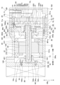
- the auxiliary bearing member 16 will be described with reference to FIGS. 1 and 2.
- the auxiliary bearing member 16 is composed of a member separate from the first housing portion 121 and is fixed to the bottom surface of the bottom portion 121c of the first housing portion 121. Specifically, the auxiliary bearing member 16 is fixed to the bottom portion 121c with respect to the bottom surface by the fastening bolt 18.
- the auxiliary bearing member 16 has a tubular body portion 161, a flange portion 162 connected to an end portion of the body portion 161 and a protrusion 93a.
- the body portion 161 and the flange portion 162, and the protrusion portion 93a are made of a steel material or an aluminum alloy.
- the body portion 161 and the flange portion 162, and the protrusion portion 93a are configured as integrally molded products.
- the body portion 161 forms an auxiliary bearing 16a inside the body portion 161.
- the auxiliary bearing 16a is composed of a slide bearing.
- the inner peripheral surface of the auxiliary bearing 16a is processed in a state where the coaxiality is accurately matched with the outer peripheral surface of the protrusion 93a.
- the auxiliary bearing 16a is integrally fixed to the auxiliary bearing member 16.
- the auxiliary bearing 16a is composed of a cylindrical steel member, a resin layer coated on the inner peripheral surface thereof, and the like.
- the auxiliary bearing 16a may be made of the same material as the body portion 161 and may be integrally formed with the auxiliary bearing member 16.
- the auxiliary bearing 16a is more effective as a tilt support when the auxiliary bearing 16a is separated from the main bearing 361a. Therefore, when the auxiliary bearing 16a is arranged away from the main bearing 361a, the motor unit 20 is arranged between the main bearing 361a and the auxiliary bearing 16a. As a result, the space inside the housing 12 can be effectively used.
- the flange portion 162 is a portion fixed to the bottom portion 121c of the first housing portion 121.
- the flange portion 162 has an annular shape.
- the flange portion 162 extends outward in the radial direction of the drive shaft 14.
- the flange portion 162 is formed with a plurality of insertion holes 162a into which the fastening bolt 18 is inserted.
- the insertion holes 162a are formed at three positions so as to be uniform in the circumferential direction of the flange portion 162.
- the auxiliary bearing member 16 of the present embodiment is fixed to the bottom portion 121c by three fastening bolts 18.
- the number of fastening bolts 18 is not limited to three, and may be any number of one or more.
- the compressor 10 is provided with an auxiliary bearing centering structure that aligns the axial center of the auxiliary bearing 16a with the axial center of the second inner peripheral surface 83 of the tubular portion 121b.
- the auxiliary bearing alignment structure includes an in-row fitting structure 93.
- the convex portion formed on the other side of the first housing portion 121 and the auxiliary bearing member 16 is fitted into the concave portion formed on one of the first housing portion 121 and the auxiliary bearing member 16 to fit the auxiliary bearing member.
- the in-row fitting structure 93 is a fitting structure in which the protrusion 93a formed in the auxiliary bearing member 16 is fitted into the recessed hole 93b formed in the first housing portion 121 to position the auxiliary bearing member 16. Is.
- Such an in-row fitting structure 93 can be formed with high accuracy by processing using general-purpose equipment such as a lathe.
- the protruding portion 93a constitutes a convex portion
- the recessed hole 93b constitutes a concave portion.
- the recessed hole 93b is a circular bottomed hole.
- the recessed hole 93b is formed in a substantially central portion of the bottom portion 121c so as to be coaxial with the second inner peripheral surface 83 of the first housing portion 121.
- the protrusion 93a has a cylindrical shape.
- the protrusion 93a has an outer peripheral surface that can be fitted inside the recessed hole 93b.
- the outer peripheral surface of the protrusion 93a is processed so as to be coaxial with the inner peripheral surface of the auxiliary bearing 16a.
- the protrusion 93a has an axial length in the axial direction of the recess hole 93b so that the tip of the protrusion 93a does not come into contact with the bottom surface of the recess hole 93b when the protrusion 93a is fitted into the recess hole 93b. It is smaller than the length of.
- the auxiliary bearing centering structure of the present embodiment is an in-row assembly in which the outer peripheral surface of the protrusion 93a having an extremely small clearance with the recessed hole 93b is assembled to the recessed hole 93b. Since the outer peripheral surface of the protrusion 93a is processed so as to be coaxial with the inner peripheral surface of the auxiliary bearing 16a, the auxiliary bearing member 16 can be accurately mounted inside the first housing portion 121 by the in-row fitting structure 93. Can be positioned.
- the auxiliary bearing member 16 is configured to be fixable to the bottom portion 121c of the first housing portion 121 in a state where the stator 21 is fixed to the first inner peripheral surface 82 of the tubular portion 121b. Specifically, in the auxiliary bearing member 16, the outer diameter of the flange portion 162 is smaller than the inner diameter of the stator 21.
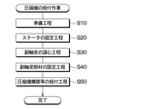
- the assembly work of the compressor 10 includes a preparation process, a fixing process of the stator 21, a centering process of the auxiliary bearing 16a, a fixing process of the auxiliary bearing member 16, and an assembly process of the compression mechanism portion 30 and the like. Includes.
- each component of the compressor 10 is prepared.
- a first housing portion 121 or the like having a first inner peripheral surface 82 and a second inner peripheral surface 83 processed in a state where the coaxiality is accurately matched is prepared.
- the stator 21 of the motor portion 20 is fixed to the first inner peripheral surface 82 of the tubular portion 121b.
- the stator 21 is fixed to the first inner peripheral surface 82 of the first housing portion 121 by shrink fitting.
- the subsequent centering step of the auxiliary bearing 16a in step S30 is a step of aligning the axial center of the auxiliary bearing 16a with the axial center of the second inner peripheral surface 83 of the tubular portion 121b.
- the protrusion 93a of the auxiliary bearing member 16 is fitted into the recessed hole 93b of the bottom portion 121c of the first housing portion 121.
- the outer peripheral surface of the protrusion 93a of the auxiliary bearing member 16 and the inner peripheral surface of the auxiliary bearing 16a are processed in a state where the coaxiality is accurately matched.
- the second inner peripheral surface 83 and the recessed hole 93b of the tubular portion 121b are machined in a state where the coaxiality is accurately matched.
- the clearance between the outer peripheral surface of the protrusion 93a and the inner peripheral surface of the recessed hole 93b is extremely small. Therefore, when the protrusion 93a is fitted into the recessed hole 93b, the deviation of the axis of the inner peripheral surface of the auxiliary bearing 16a with respect to the axis of the second inner peripheral surface 83 of the tubular portion 121b is suppressed.
- the auxiliary bearing member 16 is attached to the first housing portion 121 with the axial center of the auxiliary bearing 16a and the axial center of the second inner peripheral surface 83 of the tubular portion 121b aligned.
- This is a step of fixing to the inner surface of the bottom portion 121c.
- the auxiliary bearing member 16 is fixed to the bottom portion 121c of the first housing portion 121 by the fastening bolt 18.
- step S50 first, the main bearing member 36 is assembled with the drive shaft 14, the main bearing member 36, the swivel scroll 34, and the fixed scroll 32. And the fixed scroll 32 are temporarily assembled by the first bolt 71. In this state, by aligning the main bearing member 36 and the fixed scroll 32, the axial misalignment between the swivel scroll 34 and the fixed scroll 32 is adjusted.
- the compression mechanism portion 30 is assembled to the first housing portion 121.
- the compression mechanism portion 30 is inserted from one side of the axial DRa into the inside of the first housing portion 121.
- the end surface 362b of the main bearing member 36 of the compression mechanism portion 30 is brought into contact with the stepped surface 81 of the first housing portion 121.
- a plurality of second bolts 72 are inserted from one side of the axial DRa toward the other side.
- the compression mechanism portion 30 is fastened and fixed to the housing 12 by a plurality of second bolts 72. Then, after assembling the compression mechanism portion 30 to the first housing portion 121, the second housing portion 122 is fixed to the first housing portion 121. Further, the inverter 25 is fixed to the outer surface of the bottom portion 121c of the first housing portion 121 before or after fixing the second housing portion 122 to the first housing portion 121. The rotor 22 of the motor unit 20 is fixed to the drive shaft 14 in advance by means such as shrink fitting before assembling the compression mechanism unit 30 to the first housing unit 121.
- the compressor 10 described above is applied to a refrigeration cycle device in which a refrigerant containing carbon dioxide as a main component circulates.
- a refrigerant containing carbon dioxide as a main component circulates.
- the difference in high and low pressure in the cycle is large as compared with the case where a Freon-based refrigerant is used. Therefore, since a high load acts on the main bearing 361a, the auxiliary bearing 16a, and the like of the compressor 10, the required level of durability for the compressor 10 is high.
- the eccentric bearing 342a, the main bearing 361a, and the auxiliary bearing 16a are composed of a slide bearing having excellent durability. As a result, even when the difference between high and low pressure in the cycle is large and a high load acts on the bearing, the reliability against wear deterioration is improved and the life can be extended as compared with the rolling bearing.
- each bearing 361a is improved in seizure resistance by suppressing a local increase in surface pressure and from the viewpoint of ensuring wear resistance by forming a good oil film. , It is necessary to align the axes of 16a as much as possible.
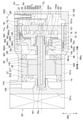
- FIG. 4 is an axial sectional view of the compressor CE1 which is the first comparative example of the present embodiment.
- the auxiliary bearing member 16 is integrally formed on the bottom portion 121c, and the axial alignment gap ⁇ p between the outer peripheral surface 30a of the compression mechanism portion 30 and the second inner peripheral surface 83 of the tubular portion 121b. Is different from the compressor 10 of the present embodiment in that is formed.
- FIG. 4 among the components of the compressor CE1 of the first comparative example, those corresponding to the components of the compressor 10 of the present embodiment are configured, whereas the components of the compressor 10 of the present embodiment are configured. It has the same code as the part.
- the auxiliary bearing member 16 is integrally formed with the bottom portion 121c, and the position of the auxiliary bearing 16a cannot be adjusted with respect to the first housing portion 121. Therefore, the assembly equipment detects the axis of the main bearing 361a while displaced the compression mechanism portion 30 relative to the first housing portion 121, aligns it with the axis of the auxiliary bearing 16a, and adjusts the state. It is necessary to tighten the second bolt 72 while holding it.
- the axial alignment gap ⁇ p of the compressor CE1 of the first comparative example is made extremely small, and the relative bearings 361a and 16a are relative to each other. It is conceivable to improve the dimensional tolerance and shape tolerance that affect the variation in coaxiality with high accuracy. In the compressor CE2 of the second comparative example, it is possible to keep the variation in the coaxiality of each bearing 361a, 16a, etc. within the range that is qualitatively acceptable by simply assembling each component.
- auxiliary bearing member 16 is integrally formed on the bottom portion 121c as in the compressor CE2 of the second comparative example, it is necessary to increase the length of the shaft of the grindstone in order to polish the auxiliary bearing 16a. There is.
- the shaft of the grindstone is lengthened, the degree of difficulty in polishing increases due to the deflection of the shaft or the swing of the grindstone, and it becomes difficult to obtain the required accuracy such as coaxiality, surface roughness, and cylindricity. Then, in order to secure the required accuracy, it is necessary to introduce dedicated equipment that enables high-precision processing, and the investment amount becomes high.
- the auxiliary bearing member 16 is configured separately from the first housing portion 121 and is fixed to the bottom surface of the bottom portion 121c of the first housing portion 121. According to this, since the inner peripheral surface of the auxiliary bearing 16a can be machined with the auxiliary bearing member 16 removed from the housing 12, the inner peripheral surface of the auxiliary bearing 16a can be accurately processed without introducing dedicated equipment. It becomes possible to process. That is, since the auxiliary bearing 16a can be polished in the state of the auxiliary bearing member 16, it is not necessary to lengthen the shaft length of the polishing grindstone, and the polishing accuracy of the auxiliary bearing 16a is high even with relatively inexpensive general-purpose equipment. Accuracy can be ensured.
- the accuracy of the auxiliary bearing 16a that supports the drive shaft 14 on the bottom portion 121c side of the first housing portion 121 without introducing dedicated equipment can be improved. Can be secured. As a result, it is possible to achieve both productivity and high quality while suppressing capital investment.
- Such a compressor 10 is effective for application to a compressor having a high level of durability requirement, such as a refrigeration cycle device in which a refrigerant containing carbon dioxide as a main component is used and a difference in high and low pressure in a cycle is large. Further, the compressor 10 of the present embodiment is effective to be applied to a compressor having a high need for small size, light weight, and low cost, such as an in-vehicle compressor. Further, in the compressor 10 of the present embodiment, for example, like a scroll type compressor, the load support of the drive shaft 14 has a cantilever structure, the drive shaft 14 and the bearing are relatively easy to tilt, and the bearing is locally supported. It is effective to apply it to a structure in which the surface pressure tends to increase.
- the auxiliary bearing member 16 is fixed to the bottom surface of the bottom portion 121c by a fastening bolt 18. According to this, a high fastening force can be obtained with a relatively small number of assembly man-hours.
- the compressor 10 has an auxiliary bearing centering structure that aligns the axial center of the auxiliary bearing 16a with the axial center of the second inner peripheral surface 83 of the tubular portion 121b. According to this, the axial misalignment between the axial center of the auxiliary bearing 16a and the axial center of the second inner peripheral surface 83 of the first housing portion 121 is suppressed.
- the compressor 10 has a main bearing centering structure that aligns the axis of the main bearing 361a with the axis of the second inner peripheral surface 83 of the tubular portion 121b. According to this, the axial deviation between the axial center of the main bearing 361a and the axial center of the second inner peripheral surface 83 of the first housing portion 121 is suppressed.
- the compressor 10 has both a main bearing centering structure and a sub-bearing centering structure, so that the axial center is displaced due to the tolerance stacking between the inner peripheral surface of the main bearing 361a and the inner peripheral surface of the sub-bearing 16a during assembly work. Can be suppressed with high accuracy. As a result, the seizure resistance can be improved by suppressing the local increase in surface pressure of each of the bearings 361a and 16a. Further, each of the bearings 361a and 16a is in a good oil film forming state and the wear resistance is improved, so that the reliability of the bearing can be improved.
- the auxiliary bearing alignment structure is an in-row fitting in which the protrusion 93a formed in the auxiliary bearing member 16 is fitted into the recessed hole 93b formed in the first housing portion 121 to position the auxiliary bearing member 16.
- the recessed hole 93b and the protrusion 93a constituting the inlay fitting structure 93 can be formed with high accuracy by processing using general-purpose equipment such as a lathe. Therefore, the positioning accuracy of the auxiliary bearing member 16 can be ensured without introducing dedicated equipment.
- the main bearing centering structure includes an in-row fitting structure 91 in which the outer periphery of the compression mechanism portion 30 is fitted into the second inner peripheral surface 83 of the first housing portion 121 to position the main bearing member 36.
- the in-row fitting structure 91 can be formed with high accuracy by processing using general-purpose equipment such as a lathe. Therefore, the positioning accuracy of the main bearing member 36 can be ensured without introducing dedicated equipment.
- the main bearing centering structure is formed by fitting a common positioning pin 92c into each of the housing hole 92a formed in the first housing portion 121 and the main bearing side hole 92b formed in the main bearing member 36. It includes a pin fitting structure 92 for positioning 36.
- the positioning pin 92c while suppressing the axial deviation of the axial center of the main bearing 361a with respect to the axial center of the second inner peripheral surface 83 of the first housing portion 121, the positioning pin 92c also positions the main bearing member 36 in the rotational direction. Can be done. Therefore, the assembling property of the main bearing member 36 to the first housing portion 121 can be ensured.
- the positioning pin 92c functions as a detent to prevent the main bearing member 36 from rotating due to the driving force of the motor unit 20. It can prevent the bearing from turning around.
- the tubular portion 121b and the bottom portion 121c of the first housing portion 121 are configured as separate bodies, the meat for forming a bolt seat or the like for fastening the two with bolts. It is necessary to give the thickness to each of the cylinder portion 121b and the bottom portion 121c.
- the first housing portion 121 is configured as an integrally molded product in which the tubular portion 121b and the bottom portion 121c are seamless. According to this, it is not necessary to provide each of the tubular portion 121b and the bottom portion 121c with a wall thickness for forming the bolt seat or the like, and it is possible to obtain the required rigidity with a relatively thin wall thickness. This can reduce the number of parts and secure the pressure resistance while suppressing the weight of the housing 12.
- the main bearing centering structure includes the in-row fitting structure 91 and the pin fitting structure 92, respectively, but the compressor 10 is not limited to this.
- the compressor 10 may have, for example, one of the fitting structure of the in-row fitting structure 91 and the pin fitting structure 92.
- an axial alignment gap ⁇ p is formed between the outer peripheral surface 30a of the compression mechanism portion 30 and the second inner peripheral surface 83 of the first housing portion 121. May be.
- the in-row fitting structure 93 a structure in which the convex portion formed in the auxiliary bearing member 16 is fitted into the concave portion formed in the bottom portion 121c of the first housing portion 121 is exemplified.
- the fitting structure 93 is not limited to this.
- the in-row fitting structure 93 may be, for example, a fitting structure in which a concave portion formed in the auxiliary bearing member 16 is fitted into a convex portion formed in the bottom portion 121c of the first housing portion 121.
- the in-row fitting structure 93 may be adapted to fit the convex portion and the concave portion having a shape other than the circular shape as long as the clearance between the concave portion and the convex portion is closed.
- the auxiliary bearing member 16 is provided with a circular flange portion 162, but the flange portion 162 is not limited to this, and may have a shape other than the circular shape. good.
- the flange portion 162 may have a substantially triangular shape, for example, as shown in FIG. According to this, the area covered by the flange portion 162 on the bottom surface of the bottom portion 121c of the first housing portion 121 can be suppressed. As a result, it becomes easy to avoid the interference between the flange portion 162 and the airtight terminal 121d, and the degree of freedom in the layout of the airtight terminal 121d can be improved.
- the compression mechanism portion 30 is fixed to the first housing portion 121 by the second bolt 72.
- the second bolt 72 may be omitted if the compression mechanism portion 30 is fixed by another means such as being sandwiched between the first housing portion 121 and the second housing portion 122. Further, even if it is not fixed, the second bolt 72 may not necessarily be present. That is, the compression mechanism portion 30 is pressed against the stepped surface 81 between the inner peripheral surfaces 82 and 83 of the first housing portion 121 due to the pressure difference generated during operation, and is substantially fixed during operation by the frictional force generated thereby. If so, the second bolt 72 may not be present. In these cases, even if a rotational force acts from the electric motor unit 20 to the compression mechanism unit 30, the positioning pin 92c of the pin fitting structure 92 receives the rotational force, so that it is possible to prevent misalignment such as turning.
- the pin fitting structure 92 described in the first embodiment is omitted.
- the pin fitting structure 94 constitutes the auxiliary bearing centering structure.
- a common positioning pin 94c is fitted into each of the bottom wall hole 94a formed in the bottom portion 121c of the first housing portion 121 and the auxiliary bearing side hole 94b formed in the auxiliary bearing member 16, and the auxiliary bearing is provided. It is a fitting structure for positioning the member 16.
- the positioning pin 94c is a cylindrical member.
- the bottom wall hole 94a is a bottomed hole having a size into which a positioning pin 94c can be inserted.
- the auxiliary bearing side hole 94b is a bottomed hole or a through hole having a size into which the positioning pin 94c can be inserted.
- a plurality of bottom wall holes 94a and auxiliary bearing side holes 94b are formed at portions facing each other in the bottom portion 121c and the auxiliary bearing member 16. Specifically, a plurality of bottom wall holes 94a are formed in a portion of the bottom surface of the bottom portion 121c facing the flange portion 162.
- a plurality of auxiliary bearing side holes 94b are formed in a portion of the flange portion 162 that is in contact with the bottom surface of the bottom portion 121c.
- the auxiliary bearing alignment structure includes the pin fitting structure 94. According to this, while suppressing the axial deviation of the axial center of the auxiliary bearing 16a with respect to the axial center of the second inner peripheral surface 83 of the first housing portion 121, the positioning pin 94c can also position the auxiliary bearing member 16 in the rotational direction. As a result, the position of the insertion hole 162a of the fastening bolt 18 of the auxiliary bearing member 16 and the screw hole formed in the bottom portion 121c can be easily aligned, so that the auxiliary bearing member 16 can be sufficiently assembled to the first housing portion 121. Can be secured.
- the auxiliary bearing alignment structure is exemplified by the pin fitting structure 94, but the auxiliary bearing alignment structure is not limited to this, for example, the in-row fitting structure 93 and Each of the pin fitting structures 94 may be included.
- the compressor 10 of the present embodiment is not provided with the auxiliary bearing alignment structure. That is, the first housing portion 121 and the auxiliary bearing member 16 are not provided with a configuration corresponding to the in-row fitting structure 93 described in the first embodiment and the pin fitting structure 94 described in the second embodiment.
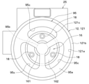
- the compressor 10 uses the centering jig 95 shown in FIGS. 9 and 10 to align the axis of the auxiliary bearing 16a with the axis of the second inner peripheral surface 83 of the tubular portion 121b in the first housing.
- the auxiliary bearing member 16 is fixed to the bottom surface of the bottom portion 121c of the portion 121.
- the centering jig 95 is a dummy shaft that imitates the drive shaft 14.
- the centering jig 95 can be fitted to the inner peripheral surface of the auxiliary bearing 16a and the second inner peripheral surface 83 of the first housing portion 121, respectively.
- the centering jig 95 has a large diameter portion 95a having an outer diameter that can be fitted to the second inner peripheral surface 83 of the tubular portion 121b and a small diameter portion having an outer diameter that can be fitted to the inner peripheral surface of the auxiliary bearing 16a. It has 95b and.
- the centering jig 95 is processed so that the axis of the large diameter portion 95a and the axis of the small diameter portion 95b match with extremely high accuracy.
- the outer diameter of the small diameter portion 95b is smaller than the outer diameter of the large diameter portion 95a.
- the large diameter portion 95a has a substantially cylindrical shape, and the outer diameter thereof is processed so that the clearance with the inner diameter of the second inner peripheral surface 83 of the tubular portion 121b is extremely small.
- a plurality of through holes 95c penetrating in the axial DRa are formed in the large diameter portion 95a.
- the through hole 95c is formed for inserting a bolt tightening jig for fastening the fastening bolt 18.
- the through hole 95c is formed at a position of the large diameter portion 95a of the flange portion 162 facing the insertion hole 162a.
- the small diameter portion 95b has a substantially cylindrical shape, and its outer diameter is processed to a size that makes the clearance with the inner diameter of the auxiliary bearing 16a extremely small.
- the small diameter portion 95b is formed with a tapered portion 95d for guidance that facilitates insertion of the auxiliary bearing 16a into the inside at the tip portion on the opposite side of the connection portion with the large diameter portion 95a.
- each component of the compressor 10 is prepared in the preparation process.
- the stator 21 of the motor unit 20 is fixed to the first inner peripheral surface 82 of the tubular portion 121b by shrink fitting.
- step S30 In the subsequent centering step of the auxiliary bearing 16a in step S30, first, the auxiliary bearing member 16 is temporarily fixed to the bottom surface of the bottom portion 121c by the fastening bolt 18. In this state, the fastening bolt 18 is not tightened to a specified torque, and the auxiliary bearing member 16 can shift its position.
- the centering jig 95 is fitted inside the first housing portion 121. That is, in the centering process, the large diameter portion 95a of the centering jig 95 is fitted into the second inner peripheral surface 83 of the tubular portion 121b, and the small diameter portion 95b of the centering jig 95 is fitted to the inner peripheral surface of the auxiliary bearing 16a. Fit into. At this point, the axial center of the second inner peripheral surface 83 of the tubular portion 121b and the axial center of the inner peripheral surface of the auxiliary bearing 16a are in a state of being suppressed from being displaced.
- step S40 the fastening bolt 18 is tightened with a specified torque to fix the auxiliary bearing member 16 to the bottom surface of the bottom portion 121c.
- a bolt tightening jig is inserted into a through hole 95c formed in the large diameter portion 95a, and the fastening bolt 18 is tightened with a specified torque by the bolt tightening jig.
- step S50 the centering jig 95 is taken out from the inside of the first housing portion 121.
- the drive shaft 14 is assembled to the auxiliary bearing 16a and the compression mechanism portion 30 is assembled to the first housing portion 121.
- the positioning accuracy of the auxiliary bearing member 16 can be ensured by the alignment jig 95 even if the compressor 10 does not have the auxiliary bearing alignment structure. According to this, it is possible to suppress the relative axial deviation between the axial center of the main bearing 361a and the axial center of the auxiliary bearing 16a with high accuracy while suppressing the product cost.
- the stator 21 is fixed to the first housing portion 121.
- the stator 21 in order for the stator 21 not to loosen under the temperature distribution environment under each operating condition of the compressor 10, it is necessary to increase the tightening allowance at the time of shrink fitting.
- the tightening allowance is large, the first housing portion The distortion of 121 becomes large.
- the constituent material of the first housing portion 121 is an aluminum alloy or the like, the temperature of the first housing portion 121 becomes high during shrink fitting, so that distortion is likely to occur due to stress relaxation or the like. These distortions of the first housing portion 121 cause the axial center of the auxiliary bearing 16a to shift.
- the axial alignment of the auxiliary bearing 16a by the centering jig 95 is performed after the fixing step of the stator 21. Therefore, the auxiliary bearing member 16 can be fixed to the bottom surface of the bottom portion 121c in a state where the shaft misalignment due to the distortion of the first housing portion 121 is canceled by the centering jig 95. That is, according to the assembling work of the present embodiment, it is possible to suppress the shaft deviation with higher accuracy.
- the centering jig 95 is not limited to this.
- the centering jig 95 is different from the third embodiment as long as it can align the axial center of the inner peripheral surface of the auxiliary bearing 16a with the axial center of the second inner peripheral surface 83 of the tubular portion 121b. It may be a thing. Further, the centering jig 95 may be configured not as a single unit but as a part of other equipment.
- the auxiliary bearing member 16 is fixed to the bottom surface of the bottom portion 121c by the fastening bolt 18, but the auxiliary bearing member 16 is fixed to the bottom surface of the bottom portion 121c by means other than the fastening bolt 18. May be.
- the compressor 10 is provided with the main bearing alignment structure and the auxiliary bearing alignment structure.
- the main bearing alignment structure and the auxiliary bearing alignment structure are the compressor 10. It is not an essential configuration in the above, and at least one alignment structure may be omitted.
- both the main bearing 361a and the auxiliary bearing 16a are made of a slide bearing, but at least one of the main bearing 361a and the auxiliary bearing 16a is made of a bearing other than the slide bearing. May be.
- the compressor 10 having the scroll type compression mechanism unit 30 is exemplified, but the compressor 10 is not limited to this, and the rotary type compression mechanism unit 30 and the vane type compression mechanism unit 30 are adopted. It may have been done.
- the compressor 10 is not limited to this, and may be used as a temperature control device used in a house, a factory, or the like. On the other hand, it is widely applicable. Further, the compressor 10 is not limited to a horizontal structure in which the motor unit 20 and the compression mechanism unit 30 are arranged in the horizontal direction. For example, the compressor unit 10 has a vertical structure in which the motor unit 20 and the compression mechanism unit 30 are arranged in the vertical DRv. It may be.
- the elements constituting the embodiment are not necessarily essential except when it is clearly stated that they are essential or when they are clearly considered to be essential in principle.
- the shape, positional relationship, etc. of a component or the like when the shape, positional relationship, etc. of a component or the like is referred to, the shape, positional relationship, etc. are not specified unless otherwise specified or limited in principle to a specific shape, positional relationship, etc. Not limited to, etc.
- the compressor comprises a compression mechanism section, a motor section, a drive shaft, and a housing.
- the housing includes a bottomed tubular first housing portion that opens on one side in the axial direction of the drive shaft, and a second housing portion that covers the opening of the first housing portion.
- the drive shaft is rotatably supported by a main bearing whose one side in the axial direction is integrally formed or fixed to the main bearing member, and the other side in the axial direction is integrally formed or integrally formed inside the body of the auxiliary bearing member. It is rotatably supported by a fixed auxiliary bearing.
- the compression mechanism portion including the main bearing member is arranged inside the tubular portion of the first housing portion.
- the auxiliary bearing member is formed separately from the first housing portion and is fixed to the bottom surface of the bottom portion of the first housing portion. According to this, since the inner peripheral surface of the auxiliary bearing can be processed with the auxiliary bearing member removed from the housing, it is possible to accurately process the inner peripheral surface of the auxiliary bearing without introducing special equipment. Will be. That is, since the auxiliary bearing can be polished in the state of the auxiliary bearing member, it is not necessary to lengthen the shaft length of the polishing grindstone, and the auxiliary bearing polishing accuracy is ensured even with relatively inexpensive general-purpose equipment. can do.
- the auxiliary bearing member is fixed to the bottom surface of the bottom portion by a fastening bolt. According to this, a high fastening force can be obtained with a relatively small number of assembly man-hours.
- the compressor is provided with an auxiliary bearing centering structure that aligns the axial center of the auxiliary bearing with the axial center of the inner peripheral surface of the insertion portion where the compression mechanism portion is inserted in the tubular portion.
- an auxiliary bearing centering structure that aligns the axial center of the auxiliary bearing with the axial center of the inner peripheral surface of the insertion portion where the compression mechanism portion is inserted in the tubular portion.
- the convex portion formed on the other side of the first housing portion and the auxiliary bearing member is fitted into the concave portion formed on one of the first housing portion and the auxiliary bearing member.
- a fitting structure that positions the sub-bearing member in.
- the convex portions and concave portions constituting the fitting structure can be formed with high accuracy by processing using general-purpose equipment such as a lathe. Therefore, since the positioning accuracy of the auxiliary bearing member can be ensured without introducing dedicated equipment, it is possible to suppress the accumulation variation of the relative axial deviation amount of the axial center of each bearing.
- a common positioning pin is fitted into each of the bottom wall hole formed in the bottom portion and the auxiliary bearing side hole formed in the auxiliary bearing member to form the auxiliary bearing member.
- the auxiliary bearing member can be positioned in the rotational direction by the positioning pin, so that the auxiliary bearing portion can be positioned. Sufficient assembling property of the bearing member can be ensured.
- the sub-bearing member is subordinated by a centering jig that can be fitted to each of the inner peripheral surface of the sub-bearing and the inner peripheral surface of the insertion portion where the compression mechanism portion is inserted among the tubular portion. It is fixed to the bottom surface of the bottom part with the axis of the bearing aligned with the axis of the insertion site.
- the positioning accuracy of the auxiliary bearing member can be ensured without adding the auxiliary bearing alignment structure to the compressor, the accumulation variation of the relative axial deviation amount of the axial center of each bearing can be ensured. Can be suppressed.
- the compressor is provided with a main bearing centering structure that aligns the axial center of the main bearing with the axial center of the inner peripheral surface of the insertion portion where the compression mechanism portion is inserted in the tubular portion. According to this, it is possible to suppress the accumulation variation of the relative axial deviation amount of the axial center of each bearing. As a result, it is possible to suppress a local increase in surface pressure and ensure good oil film formation in each bearing, and it is possible to secure the reliability of each bearing.
- the main bearing centering structure includes a fitting structure in which the outer peripheral surface of the compression mechanism portion is fitted to the inner peripheral surface of the insertion portion to position the main bearing member.
- a fitting structure can be formed with high accuracy by processing using general-purpose equipment such as a lathe. Therefore, since the positioning accuracy of the main bearing member can be ensured without introducing dedicated equipment, it is possible to suppress the accumulation variation of the relative axial deviation amount of the axial center of each bearing.
- the main bearing centering structure is formed by fitting a common positioning pin into each of the housing hole formed in the first housing portion and the main bearing side hole formed in the main bearing member. Includes a pin fitting structure for positioning.
- the positioning pin can also position the main bearing member in the rotational direction, so that the main bearing with respect to the first housing portion can be positioned. Sufficient assembling property of the member can be ensured.
- the positioning pin functions as a detent to prevent the main bearing member from rotating due to the driving force of the motor unit.
- At least one of the main bearing and the auxiliary bearing is composed of a plain bearing. According to this, it is possible to secure the reliability against wear deterioration and extend the life while ensuring the seizure resistance of the bearing of the drive shaft.
- the compression mechanism portion includes a fixed scroll fixed to the first housing portion and a swivel scroll that compresses the fluid by engaging with the fixed scroll when swiveling due to the rotation of the drive shaft. ..
- the scroll type compression mechanism portion having less torque fluctuation, the load of each bearing is suppressed, so that the seizure resistance and wear resistance of the bearing can be ensured.
- the axial center of the auxiliary bearing and the axial center of the inner peripheral surface of the insertion portion where the compression mechanism portion is inserted in the cylindrical portion are aligned with each other.
- the bearing member is fixed to the inner surface of the bottom of the first housing portion.
- the axial center of the auxiliary bearing and the inside of the insertion portion are fitted. Align with the axis of the peripheral surface. According to this, since the positioning accuracy of the auxiliary bearing member can be ensured without adding the auxiliary bearing alignment structure to the compressor, the relative of the axial center of the main bearing and the axial center of the auxiliary bearing. It is possible to suppress the misalignment of the axis with high accuracy.
Abstract
A compressor (10) is provided with a compressing mechanism unit (30), an electric motor unit (20), a drive shaft (14), and a housing (12). The housing includes a first housing unit (121) having a bottomed columnar shape that opens on one side in the axial direction of the drive shaft, and a second housing unit (122) covering the opening in the first housing unit. One side of the drive shaft in the axial direction is rotatably supported by a main bearing (361a) integrally formed with or fixed to a main bearing member (36) constituting a part of the compressing mechanism unit. The other side of the drive shaft in the axial direction is rotatably supported by a sub bearing (16a) integrally formed with or fixed to the inside of a columnar trunk (161) of a sub bearing member (16). The compressing mechanism unit including the main bearing member is disposed inside a cylindrical part (121b) of the first housing unit. The sub bearing member is configured separately from the first housing unit, and is fixed to a bottom part (121c) of the first housing unit.
Description
本出願は、2020年8月5日に出願された日本出願番号2020-133286号に基づくもので、ここにその記載内容が参照により組み入れられる。
This application is based on Japanese Application No. 2020-133286 filed on August 5, 2020, the contents of which are incorporated herein by reference.
本開示は、吸入した流体を圧縮して吐出する圧縮機および圧縮機の製造方法に関する。
The present disclosure relates to a compressor that compresses and discharges the sucked fluid and a method for manufacturing the compressor.
特許文献1には、スクロール型圧縮機が開示されている。この圧縮機は、圧縮機構部と、電動機部と、電動機部が出力する駆動力を圧縮機構部に伝達する駆動軸と、圧縮機構部等を収容するハウジングと、を備える。駆動軸は、軸方向の一方側が、圧縮機構部の一部を構成する主軸受部材に形成された主軸受によって回転可能に支持され、軸方向の他方側が副軸受部材のうち筒形状の胴部の内側に形成された副軸受によって回転可能に支持されている。ハウジングは、駆動軸の軸方向の一方側が開口する有底筒形状のハウジング本体部を含み、当該ハウジング本体部の底部分の底面に対して副軸受部材が一体に形成されている。そして、圧縮機構部とハウジング本体部の筒状部分の内周面との間には、主軸受の軸心および副軸受の軸心を合わせるための調心用の隙間が形成されている。
Patent Document 1 discloses a scroll type compressor. This compressor includes a compression mechanism unit, an electric motor unit, a drive shaft for transmitting a driving force output by the electric motor unit to the compression mechanism unit, and a housing for accommodating the compression mechanism unit and the like. One side of the drive shaft in the axial direction is rotatably supported by a main bearing formed in a main bearing member forming a part of the compression mechanism portion, and the other side in the axial direction is a tubular body portion of the auxiliary bearing member. It is rotatably supported by an auxiliary bearing formed inside the. The housing includes a bottomed tubular housing body portion in which one side in the axial direction of the drive shaft opens, and an auxiliary bearing member is integrally formed with the bottom surface of the bottom portion of the housing body portion. A centering gap for aligning the axis of the main bearing and the axis of the sub-bearing is formed between the compression mechanism portion and the inner peripheral surface of the tubular portion of the housing main body portion.
特許文献1に記載の圧縮機の組付作業では、圧縮機構部をハウジング本体部の筒状部分の内周面に対して相対的に変位させながら主軸受の軸心を検出するとともに、主軸心の軸心を副軸受の軸心に合わせ、その状態を保持しながらハウジング本体部に固定する。
In the compressor assembly work described in Patent Document 1, the axis of the main bearing is detected while the compression mechanism portion is displaced relative to the inner peripheral surface of the tubular portion of the housing main body, and the spindle center is detected. Align the axis of the sub-bearing with the axis of the auxiliary bearing, and fix it to the housing body while maintaining that state.
このような組付作業は、圧縮機構部を変位させながら変位量を精度良く検出することを繰り返す必要があり、設備コストおよびサイクルタイムの増加を招くので、車載用圧縮機等のような大量生産される製品には不向きである。
In such assembly work, it is necessary to repeatedly detect the displacement amount with high accuracy while displacementing the compression mechanism portion, which leads to an increase in equipment cost and cycle time. Therefore, mass production such as an in-vehicle compressor or the like is performed. It is not suitable for products that are used.
これらを踏まえ、本発明者らは、圧縮機構部とハウジング本体部との隙間を小さくするとともに、ハウジング本体部の圧縮機構部が挿入される挿入部位の軸心と副軸受の軸心との同軸度の精度を高めることで、各軸受の軸心に合わせることを検討している。本発明者らの検討によれば、本発明者らが検討している構成を実現するためには、ハウジング本体部のうち圧縮機構部の挿入部位および副軸受の内周面それぞれを精度よく加工する必要がある。
しかし、特許文献1の如く、副軸受を含む副軸受部材がハウジング本体部の底部分に一体形成されている場合、副軸受の内周面を精度よく加工することが困難であり、副軸受の内周面を加工するための専用の設備を導入する必要がある。例えば、副軸受が滑り軸受で構成されている場合、ハウジング本体部の開口から底部分に達する程度の長さを有する砥石を用いて軸受面の研磨加工を行うことになる。この場合、研磨加工時の砥石の振れ回りが生じ易くなることで研磨加工の難易度が著しく上がってしまうため、専用の設備の導入が避けられない。 Based on these, the present inventors reduce the gap between the compression mechanism portion and the housing main body portion, and at the same time, coaxialize the axial center of the insertion portion into which the compression mechanism portion of the housing main body portion is inserted with the axial center of the auxiliary bearing. We are considering aligning with the axis of each bearing by increasing the accuracy of the degree. According to the study by the present inventors, in order to realize the configuration studied by the present inventors, the insertion portion of the compression mechanism portion and the inner peripheral surface of the auxiliary bearing of the housing main body are each processed with high accuracy. There is a need to.
However, as in Patent Document 1, when the auxiliary bearing member including the auxiliary bearing is integrally formed on the bottom portion of the housing main body, it is difficult to accurately process the inner peripheral surface of the auxiliary bearing, and the auxiliary bearing It is necessary to introduce dedicated equipment for processing the inner peripheral surface. For example, when the auxiliary bearing is composed of a slide bearing, the bearing surface is polished using a grindstone having a length that reaches the bottom portion from the opening of the housing main body portion. In this case, the grindstone tends to run around during the polishing process, which significantly increases the difficulty of the polishing process, and therefore the introduction of dedicated equipment is unavoidable.
本開示は、有底筒形状のハウジング部を有する圧縮機において、専用の設備を導入することなく、ハウジング部の底部分側で駆動軸を支持する軸受の精度を確保することを目的とする。
The purpose of the present disclosure is to ensure the accuracy of the bearing that supports the drive shaft on the bottom portion side of the housing portion in the compressor having the bottomed tubular housing portion without introducing dedicated equipment.
本開示の1つの観点によれば、
圧縮機は、
流体を圧縮する圧縮機構部(30)と、
圧縮機構部を駆動する駆動力を出力する電動機部(20)と、
電動機部が出力する駆動力を圧縮機構部に伝達する駆動軸(14)と、
圧縮機構部、電動機部、および駆動軸を収容するハウジング(12)と、を備え、
ハウジングは、駆動軸の軸方向の一方側が開口する有底筒形状の第1ハウジング部(121)と、第1ハウジング部の開口を覆う第2ハウジング部(122)とを含み、
駆動軸における軸方向の一方側は、圧縮機構部の一部を構成する主軸受部材(36)に一体的に形成または固定される主軸受(361a)によって回転可能に支持され、
駆動軸における軸方向の他方側は、筒形状の胴部(161)を含む副軸受部材(16)のうち胴部の内側に一体的に形成または固定される副軸受(16a)によって回転可能に支持され、
主軸受部材を含む圧縮機構部は、第1ハウジング部の筒状部分(121b)の内側に配置され、
副軸受部材は、第1ハウジング部とは別体で構成されるとともに、第1ハウジング部の底部分(121c)の底面に固定されている。 According to one aspect of the disclosure,
The compressor is
The compression mechanism (30) that compresses the fluid,
The motor unit (20) that outputs the driving force that drives the compression mechanism unit, and
A drive shaft (14) that transmits the driving force output by the motor unit to the compression mechanism unit,
A housing (12) for accommodating a compression mechanism unit, a motor unit unit, and a drive shaft is provided.
The housing includes a bottomed tubular first housing portion (121) that opens on one side in the axial direction of the drive shaft, and a second housing portion (122) that covers the opening of the first housing portion.
One side of the drive shaft in the axial direction is rotatably supported by a main bearing (361a) integrally formed or fixed to a main bearing member (36) that constitutes a part of the compression mechanism.
The other side of the drive shaft in the axial direction can be rotated by an auxiliary bearing (16a) integrally formed or fixed to the inside of the auxiliary bearing member (16) including a tubular body portion (161). Supported,
The compression mechanism portion including the main bearing member is arranged inside the cylindrical portion (121b) of the first housing portion.
The auxiliary bearing member is formed separately from the first housing portion and is fixed to the bottom surface of the bottom portion (121c) of the first housing portion.
このように、副軸受を含む副軸受部材が第1ハウジング部とは別体で構成されていれば、ハウジングから副軸受部材を取り外した状態で副軸受の内周面を加工することできるので、専用の設備を導入することなく、副軸受の内周面を精度よく加工することが可能となる。
In this way, if the auxiliary bearing member including the auxiliary bearing is configured separately from the first housing portion, the inner peripheral surface of the auxiliary bearing can be machined with the auxiliary bearing member removed from the housing. It is possible to accurately process the inner peripheral surface of the auxiliary bearing without introducing dedicated equipment.
したがって、有底筒形状の第1ハウジング部を有する圧縮機において、専用の設備を導入することなく、第1ハウジング部の底部分側で駆動軸を支持する副軸受の精度を確保することができる。この結果、設備投資を抑えつつ、生産性と高品質を両立させることが可能となる。
Therefore, in a compressor having a bottomed cylinder-shaped first housing portion, the accuracy of the auxiliary bearing that supports the drive shaft on the bottom portion side of the first housing portion can be ensured without introducing dedicated equipment. .. As a result, it is possible to achieve both productivity and high quality while suppressing capital investment.
本開示の別の観点によれば、
流体を圧縮する圧縮機構部(30)と、
圧縮機構部を駆動する駆動力を出力する電動機部(20)と、
電動機部が出力する駆動力を圧縮機構部に伝達する駆動軸(14)と、
圧縮機構部、電動機部、および駆動軸を収容するハウジング(12)と、を備え、
ハウジングは、駆動軸の軸方向の一方側が開口する有底筒形状の第1ハウジング部(121)と、第1ハウジング部の開口を覆う第2ハウジング部(122)とを含み、
駆動軸における軸方向の一方側は、圧縮機構部の一部を構成する主軸受部材(36)に一体的に形成または固定される主軸受(361a)によって回転可能に支持され、
駆動軸における軸方向の他方側は、筒形状の胴部(161)を含む副軸受部材(16)のうち胴部の内側に一体的に形成または固定される副軸受(16a)によって回転可能に支持され、
主軸受部材を含む圧縮機構部は、第1ハウジング部の筒状部分(121b)の内側に配置され、
副軸受部材は、第1ハウジング部とは別体で構成される圧縮機の製造方法であって、
副軸受の軸心と筒状部分のうち圧縮機構部が挿入される挿入部位の内周面の軸心とを合わせることと、
副軸受の軸心と挿入部位の内周面の軸心とを合わせた状態で副軸受部材を第1ハウジング部の底部の内面に固定することと、を含む。 According to another aspect of this disclosure,
The compression mechanism (30) that compresses the fluid,
The motor unit (20) that outputs the driving force that drives the compression mechanism unit, and
A drive shaft (14) that transmits the driving force output by the motor unit to the compression mechanism unit,
A housing (12) for accommodating a compression mechanism unit, a motor unit unit, and a drive shaft is provided.
The housing includes a bottomed tubular first housing portion (121) that opens on one side in the axial direction of the drive shaft, and a second housing portion (122) that covers the opening of the first housing portion.
One side of the drive shaft in the axial direction is rotatably supported by a main bearing (361a) integrally formed or fixed to a main bearing member (36) that constitutes a part of the compression mechanism.
The other side of the drive shaft in the axial direction can be rotated by an auxiliary bearing (16a) integrally formed or fixed to the inside of the auxiliary bearing member (16) including a tubular body portion (161). Supported,
The compression mechanism portion including the main bearing member is arranged inside the cylindrical portion (121b) of the first housing portion.
The auxiliary bearing member is a method for manufacturing a compressor that is configured separately from the first housing portion.
Aligning the axis of the auxiliary bearing with the axis of the inner peripheral surface of the insertion site where the compression mechanism is inserted out of the tubular part
It includes fixing the auxiliary bearing member to the inner surface of the bottom portion of the first housing portion in a state where the axial center of the auxiliary bearing and the axial center of the inner peripheral surface of the insertion portion are aligned.
これによると、第1ハウジング部に取り付ける前の段階で副軸受部材の副軸受の内周面を加工することできるので、専用の設備を導入することなく、副軸受の内周面を精度よく加工することが可能となる。
According to this, since the inner peripheral surface of the auxiliary bearing of the auxiliary bearing member can be processed before it is attached to the first housing portion, the inner peripheral surface of the auxiliary bearing can be accurately processed without introducing dedicated equipment. It becomes possible to do.
したがって、有底筒形状の第1ハウジング部を有する圧縮機において、専用の設備を導入することなく、第1ハウジング部の底部分側で駆動軸を支持する副軸受の精度を確保することができる。
Therefore, in a compressor having a bottomed cylinder-shaped first housing portion, the accuracy of the auxiliary bearing that supports the drive shaft on the bottom portion side of the first housing portion can be ensured without introducing dedicated equipment. ..
なお、各構成要素等に付された括弧付きの参照符号は、その構成要素等と後述する実施形態に記載の具体的な構成要素等との対応関係の一例を示すものである。
The reference numerals in parentheses attached to each component or the like indicate an example of the correspondence between the component or the like and the specific component or the like described in the embodiment described later.
以下、本開示の実施形態について図面を参照して説明する。なお、以下の実施形態において、先行する実施形態で説明した事項と同一もしくは均等である部分には、同一の参照符号を付し、その説明を省略する場合がある。また、実施形態において、構成要素の一部だけを説明している場合、構成要素の他の部分に関しては、先行する実施形態において説明した構成要素を適用することができる。以下の実施形態は、特に組み合わせに支障が生じない範囲であれば、特に明示していない場合であっても、各実施形態同士を部分的に組み合わせることができる。
Hereinafter, embodiments of the present disclosure will be described with reference to the drawings. In the following embodiments, the same reference numerals may be given to parts that are the same as or equal to those described in the preceding embodiments, and the description thereof may be omitted. Further, when only a part of the component is described in the embodiment, the component described in the preceding embodiment can be applied to the other part of the component. The following embodiments can be partially combined with each other as long as the combination is not particularly hindered, even if not explicitly stated.
(第1実施形態)
本実施形態について、図1~図5を参照して説明する。本実施形態では、本開示の圧縮機10を、車両用空調装置を構成する冷凍サイクル装置の車載用圧縮機に適用した例を説明する。 (First Embodiment)
This embodiment will be described with reference to FIGS. 1 to 5. In this embodiment, an example in which thecompressor 10 of the present disclosure is applied to an in-vehicle compressor of a refrigeration cycle device constituting a vehicle air conditioner will be described.
本実施形態について、図1~図5を参照して説明する。本実施形態では、本開示の圧縮機10を、車両用空調装置を構成する冷凍サイクル装置の車載用圧縮機に適用した例を説明する。 (First Embodiment)
This embodiment will be described with reference to FIGS. 1 to 5. In this embodiment, an example in which the
冷凍サイクル装置は、蒸気圧縮式の冷凍サイクルを構成する。冷凍サイクル装置は、流体である冷媒を圧縮して吐出する圧縮機10、圧縮機10から吐出された冷媒を放熱させる放熱器、放熱器から流出した冷媒を減圧させる減圧機器、減圧機器で減圧された冷媒を蒸発させる蒸発器を含んでいる。冷凍サイクル装置に用いられる冷媒の主成分は、二酸化炭素である。二酸化炭素は、フロン系冷媒よりも低温で超臨界状態になる。冷媒には、圧縮機10の内部の各摺動部位を潤滑する潤滑油が混合されている。潤滑油の一部は、冷媒とともにサイクル内を循環する。なお、冷媒は、フロン系冷媒であってもよい。
The refrigeration cycle device constitutes a steam compression type refrigeration cycle. The refrigeration cycle device is decompressed by a compressor 10 that compresses and discharges a refrigerant as a fluid, a radiator that dissipates the refrigerant discharged from the compressor 10, a decompression device that decompresses the refrigerant that flows out of the radiator, and a decompression device. It contains an evaporator that evaporates the refrigerant. The main component of the refrigerant used in the refrigeration cycle device is carbon dioxide. Carbon dioxide becomes a supercritical state at a lower temperature than Freon-based refrigerants. The refrigerant is mixed with lubricating oil that lubricates each sliding portion inside the compressor 10. Part of the lubricating oil circulates in the cycle together with the refrigerant. The refrigerant may be a fluorocarbon-based refrigerant.
以下、図1を参照して圧縮機10の詳細について説明する。図1は、圧縮機10の駆動軸14の軸心CLに沿って切断した断面を示す軸方向断面図である。なお、図1中の上下を示す矢印は、圧縮機10を車両に搭載した状態における上下方向DRvを示している。図1中の矢印「DRa」は、駆動軸14の軸方向DRaを示している。
Hereinafter, the details of the compressor 10 will be described with reference to FIG. FIG. 1 is an axial cross-sectional view showing a cross section cut along the axial center CL of the drive shaft 14 of the compressor 10. The vertical arrows in FIG. 1 indicate the vertical DRv when the compressor 10 is mounted on the vehicle. The arrow “DRa” in FIG. 1 indicates the axial DRa of the drive shaft 14.
図1に示すように、圧縮機10は、ハウジング12と、駆動軸14と、電動機部20と、インバータ25と、圧縮機構部30とを備える。ハウジング12の内部に、駆動軸14と、電動機部20と、圧縮機構部30とが収容されている。圧縮機10は、電動圧縮機である。電動機部20を動力源として駆動軸14が回転する。駆動軸14の回転に伴って圧縮機構部30が駆動される。圧縮機10は、駆動軸14の軸心CLが略水平方向に延びるとともに、圧縮機構部30と電動機部20とが略水平方向に並んで配置される横置構造である。略水平方向は、重力方向に対して交差する方向である。
As shown in FIG. 1, the compressor 10 includes a housing 12, a drive shaft 14, an electric motor unit 20, an inverter 25, and a compression mechanism unit 30. A drive shaft 14, an electric motor unit 20, and a compression mechanism unit 30 are housed inside the housing 12. The compressor 10 is an electric compressor. The drive shaft 14 rotates with the electric motor unit 20 as a power source. The compression mechanism unit 30 is driven as the drive shaft 14 rotates. The compressor 10 has a horizontal structure in which the axial center CL of the drive shaft 14 extends in a substantially horizontal direction, and the compression mechanism unit 30 and the motor unit 20 are arranged side by side in a substantially horizontal direction. The substantially horizontal direction is a direction that intersects the direction of gravity.
ハウジング12は、圧縮機10の外殻を構成する。ハウジング12は、第1ハウジング部121と、第2ハウジング部122とを有する。第1ハウジング部121および第2ハウジング部122は、アルミニウムまたはアルミニウム合金で構成されている。
The housing 12 constitutes the outer shell of the compressor 10. The housing 12 has a first housing portion 121 and a second housing portion 122. The first housing portion 121 and the second housing portion 122 are made of aluminum or an aluminum alloy.
第1ハウジング部121は、駆動軸14の軸方向DRaの一方側が開口する有底筒形状である。換言すれば、第1ハウジング部121は、断面がU字形状となるカップ状の形状を有する。具体的には、第1ハウジング部121は、円筒形状の筒部121bと、底部121cとを有する。筒部121bは、軸方向DRaの一方側に開口部121aを有する。底部121cは、筒部121bにおける軸方向DRaの他方側の端部に接続されている。第1ハウジング部121は、筒部121bと底部121cとが継ぎ目のない一体成形品として構成されている。底部121cは、インバータ25を密着させることが可能なように外面の一部が平坦になっている。
The first housing portion 121 has a bottomed cylinder shape in which one side of the drive shaft 14 in the axial direction DRa opens. In other words, the first housing portion 121 has a cup-shaped shape having a U-shaped cross section. Specifically, the first housing portion 121 has a cylindrical tubular portion 121b and a bottom portion 121c. The tubular portion 121b has an opening 121a on one side of the axial DRa. The bottom portion 121c is connected to the other end of the axial DRa in the tubular portion 121b. The first housing portion 121 is configured as an integrally molded product in which the tubular portion 121b and the bottom portion 121c are seamlessly molded. A part of the outer surface of the bottom portion 121c is flat so that the inverter 25 can be brought into close contact with the bottom portion 121c.
第1ハウジング部121は、筒部121bに段差部80が形成された段付き形状になっている。すなわち、第1ハウジング部121は、第1内周面82と、第2内周面83と、段差面81とを有する。第1内周面82、段差面81、第2内周面83は、この順に底部121cからの距離が小さくなっている。換言すれば、第1内周面82、段差面81、第2内周面83は、この順に開口部121aからの距離が大きくなっている。第1内周面82および第2内周面83は、駆動軸14の軸心CLを中心に同心円となるように円筒形状に形成されている。第1内周面82は、第1ハウジング部121のうち電動機部20が配置される部位である。第1内周面82は、円筒形状である。第2内周面83は、第1内周面82よりも軸方向DRaの一方側に位置する。第2内周面83は、円筒形状である。第2内周面83は、第1ハウジング部121のうち圧縮機構部30が挿入される挿入部位の内周面である。圧縮機構部30の外径は、電動機部20の外径よりも大きい。このため、第2内周面83の直径は、第1内周面82の直径よりも大きい。段差面81は、第1内周面82と第2内周面83とをつないでいる。段差面81は、軸方向DRaに直交する方向に延びている。段差面81は、後述の主軸受部材36の軸受固定部362に対して直に当接している。なお、段差面81は、軸受固定部362に対して介在物を介して当接していてもよい。また、筒部121bにおける圧縮機構部30が挿入される挿入部位は、筒部121bのうち、段差面81よりも軸方向DRaの一方側(すなわち、開口部121a側)に位置する部位である。
The first housing portion 121 has a stepped shape in which a step portion 80 is formed on the tubular portion 121b. That is, the first housing portion 121 has a first inner peripheral surface 82, a second inner peripheral surface 83, and a stepped surface 81. The distances of the first inner peripheral surface 82, the stepped surface 81, and the second inner peripheral surface 83 from the bottom portion 121c are reduced in this order. In other words, the distances of the first inner peripheral surface 82, the stepped surface 81, and the second inner peripheral surface 83 from the opening 121a increase in this order. The first inner peripheral surface 82 and the second inner peripheral surface 83 are formed in a cylindrical shape so as to be concentric circles about the axial center CL of the drive shaft 14. The first inner peripheral surface 82 is a portion of the first housing portion 121 where the motor portion 20 is arranged. The first inner peripheral surface 82 has a cylindrical shape. The second inner peripheral surface 83 is located on one side of the axial DRa with respect to the first inner peripheral surface 82. The second inner peripheral surface 83 has a cylindrical shape. The second inner peripheral surface 83 is the inner peripheral surface of the insertion portion of the first housing portion 121 into which the compression mechanism portion 30 is inserted. The outer diameter of the compression mechanism portion 30 is larger than the outer diameter of the motor portion 20. Therefore, the diameter of the second inner peripheral surface 83 is larger than the diameter of the first inner peripheral surface 82. The step surface 81 connects the first inner peripheral surface 82 and the second inner peripheral surface 83. The step surface 81 extends in a direction orthogonal to the axial DRa. The step surface 81 is in direct contact with the bearing fixing portion 362 of the main bearing member 36 described later. The stepped surface 81 may be in contact with the bearing fixing portion 362 via an inclusion. Further, the insertion portion of the tubular portion 121b into which the compression mechanism portion 30 is inserted is a portion of the tubular portion 121b located on one side (that is, the opening 121a side) of the axial DRa with respect to the stepped surface 81.
第1ハウジング部121は、筒部121bの内周面に対して主軸受部材36を含む圧縮機構部30が配置されるとともに、底部121cに筒状の胴部161を含む副軸受部材16が固定されている。本実施形態の第1ハウジング部121では、筒部121bが第1ハウジング部121の筒状部分を構成し、底部121cが第1ハウジング部121の底部分を構成する。
In the first housing portion 121, the compression mechanism portion 30 including the main bearing member 36 is arranged on the inner peripheral surface of the tubular portion 121b, and the auxiliary bearing member 16 including the tubular body portion 161 is fixed to the bottom portion 121c. Has been done. In the first housing portion 121 of the present embodiment, the cylindrical portion 121b constitutes the tubular portion of the first housing portion 121, and the bottom portion 121c constitutes the bottom portion of the first housing portion 121.
第2ハウジング部122は、第1ハウジング部121に対して軸方向DRaの一方側の位置で、第1ハウジング部121の開口を覆っている。第2ハウジング部122は、図示しない蓋部用ボルトによって、第1ハウジング部121に締結固定されている。第1ハウジング部121の軸方向DRaの一方側の端部と第2ハウジング部122との間には、図示しないシール部材が介在している。これにより、ハウジング12は、密閉されている。
The second housing portion 122 covers the opening of the first housing portion 121 at a position on one side of the axial DRa with respect to the first housing portion 121. The second housing portion 122 is fastened and fixed to the first housing portion 121 by a lid bolt (not shown). A seal member (not shown) is interposed between one end of the first housing portion 121 in the axial direction DRa and the second housing portion 122. As a result, the housing 12 is hermetically sealed.
電動機部20は、インバータ25からの給電により駆動される三相交流モータで構成されている。電動機部20は、ステータ21の内側にロータ22が配置されるインナーロータモータとして構成されている。
The motor unit 20 is composed of a three-phase AC motor driven by power supply from the inverter 25. The electric motor unit 20 is configured as an inner rotor motor in which the rotor 22 is arranged inside the stator 21.
ステータ21は、磁性材からなるステータコア211と、ステータコア211に巻き付けられたコイル212とを有する。ステータ21は、インバータ25から電力が供給されると、ロータ22を回転させる回転磁界を発生させる。ステータ21は、焼き嵌めによって筒部121bの第1内周面82に固定されている。
The stator 21 has a stator core 211 made of a magnetic material and a coil 212 wound around the stator core 211. When power is supplied from the inverter 25, the stator 21 generates a rotating magnetic field that rotates the rotor 22. The stator 21 is fixed to the first inner peripheral surface 82 of the tubular portion 121b by shrink fitting.
ロータ22は、内側に駆動軸14が圧入等によって固定された円筒形状の部材である。ロータ22の内部には、図示しない永久磁石が配置されている。また、ロータ22の側面には、旋回スクロール34等の偏心回転のアンバランスを相殺するためのバランスウェイト221、222が取り付けられている。
The rotor 22 is a cylindrical member in which the drive shaft 14 is fixed to the inside by press fitting or the like. A permanent magnet (not shown) is arranged inside the rotor 22. Further, balance weights 221 and 222 for canceling the imbalance of eccentric rotation such as the swivel scroll 34 are attached to the side surface of the rotor 22.
インバータ25は、ステータ21に対して電力を供給する装置である。インバータ25は、ハウジング12の外側に対して取り付けられている。具体的には、インバータ25は、第1ハウジング部121の底部121cの外面に対して取り付けられている。
The inverter 25 is a device that supplies electric power to the stator 21. The inverter 25 is attached to the outside of the housing 12. Specifically, the inverter 25 is attached to the outer surface of the bottom portion 121c of the first housing portion 121.
このように構成される電動機部20は、インバータ25からステータ21に電力が供給されてステータ21の周囲に回転磁界が発生すると、ロータ22および駆動軸14が一体に回転する。
In the motor unit 20 configured in this way, when electric power is supplied from the inverter 25 to the stator 21 and a rotating magnetic field is generated around the stator 21, the rotor 22 and the drive shaft 14 rotate integrally.
ここで、インバータ25と電動機部20とは、図示しない電気配線等が、第1ハウジング部121の底部121cに設けられた図示しない気密端子を介して電気的に接続されている。このため、ハウジング12は、密閉構造である。
Here, the inverter 25 and the motor unit 20 are electrically connected to each other via an airtight terminal (not shown) provided on the bottom portion 121c of the first housing unit 121, such as electrical wiring (not shown). Therefore, the housing 12 has a closed structure.
ハウジング12の第1ハウジング部121には、蒸発器を通過した低圧冷媒を吸い込む吸入口125が形成されている。具体的には、吸入口125は、第1ハウジング部121のうち電動機部20よりも軸方向DRaの他方側に形成されている。吸入口125には、蒸発器に連なる図示しない吸入配管が接続されている。
The first housing portion 121 of the housing 12 is formed with a suction port 125 for sucking the low-pressure refrigerant that has passed through the evaporator. Specifically, the suction port 125 is formed on the other side of the first housing portion 121 in the axial direction DRa with respect to the motor portion 20. A suction pipe (not shown) connected to the evaporator is connected to the suction port 125.
蒸発器を通過した低圧冷媒は、吸入口125から電動機部20が配置されたハウジング12の内部に吸い込まれる。ハウジング12の内部に吸い込まれた低圧冷媒は、圧縮機構部30の図示しない吸入口より、圧縮機構部30の内部に吸入される。このため、電動機部20が配置されたハウジング12の内部は、低温雰囲気となっている。これにより、電動機部20およびインバータ25を冷却することができる。特に、インバータ25は、底部121cの平坦な部位に取り付けられているので、運転時にインバータ25が発熱してもその熱を効率的に底部121cに熱伝導させて、インバータ25を冷却することができる。よって、電動機部20およびインバータ25の効率向上および信頼性向上を図ることができる。
The low-pressure refrigerant that has passed through the evaporator is sucked into the inside of the housing 12 in which the motor unit 20 is arranged from the suction port 125. The low-pressure refrigerant sucked into the inside of the housing 12 is sucked into the inside of the compression mechanism portion 30 from a suction port (not shown) of the compression mechanism portion 30. Therefore, the inside of the housing 12 in which the motor unit 20 is arranged has a low temperature atmosphere. As a result, the motor unit 20 and the inverter 25 can be cooled. In particular, since the inverter 25 is attached to a flat portion of the bottom 121c, even if the inverter 25 generates heat during operation, the heat can be efficiently conducted to the bottom 121c to cool the inverter 25. .. Therefore, it is possible to improve the efficiency and reliability of the motor unit 20 and the inverter 25.
一方、ハウジング12の第2ハウジング部122には、圧縮機構部30で圧縮された高圧冷媒を吐出する吐出口126が形成されている。吐出口126は、ハウジング12のうち圧縮機構部30に対して軸方向DRaの一方側に形成されている。
On the other hand, the second housing portion 122 of the housing 12 is formed with a discharge port 126 for discharging the high-pressure refrigerant compressed by the compression mechanism portion 30. The discharge port 126 is formed on one side of the housing 12 in the axial direction DRa with respect to the compression mechanism portion 30.
また、第2ハウジング部122の内部には、高圧マフラ室51と、オイル分離室52と、高圧貯油室53とが形成されている。高圧マフラ室51は、吐出孔323と連通している。高圧マフラ室51は、吐出孔323から吐出された冷媒の吐出脈動を軽減するための空間部である。オイル分離室52は、高圧マフラ室51と連通している。オイル分離室52は、高圧マフラ室51から流入した高圧冷媒から潤滑オイルを分離するための空間部である。オイル分離室52には、オイル分離室52に流入した高圧冷媒から潤滑オイルを分離するオイル分離器54が収容されている。オイル分離器54は、パイプ状である。オイル分離器54は、吐出口126に圧入等によって固定されている。高圧貯油室53は、オイル分離器54により分離された潤滑オイルを貯留する空間部である。
Further, a high-pressure muffler chamber 51, an oil separation chamber 52, and a high-pressure oil storage chamber 53 are formed inside the second housing portion 122. The high pressure muffler chamber 51 communicates with the discharge hole 323. The high-pressure muffler chamber 51 is a space for reducing the discharge pulsation of the refrigerant discharged from the discharge hole 323. The oil separation chamber 52 communicates with the high pressure muffler chamber 51. The oil separation chamber 52 is a space for separating lubricating oil from the high-pressure refrigerant flowing in from the high-pressure muffler chamber 51. The oil separation chamber 52 contains an oil separator 54 that separates lubricating oil from the high-pressure refrigerant that has flowed into the oil separation chamber 52. The oil separator 54 has a pipe shape. The oil separator 54 is fixed to the discharge port 126 by press fitting or the like. The high-pressure oil storage chamber 53 is a space for storing the lubricating oil separated by the oil separator 54.
駆動軸14は、ロータ22よりも軸方向DRaの一方側に位置する一方側部分141を有する。圧縮機構部30は、電動機部20に対して駆動軸14の軸方向DRaの一方側に位置する。一方側部分141は、圧縮機構部30と係合している。駆動軸14は、電動機部20にて発生する駆動力を圧縮機構部30に伝達する。一方側部分141は、後述する圧縮機構部30の主軸受部材36が有する主軸受361aによって回転可能に支持されている。
The drive shaft 14 has a one-sided portion 141 located on one side of the axial DRa with respect to the rotor 22. The compression mechanism unit 30 is located on one side of the drive shaft 14 in the axial direction DRa with respect to the motor unit 20. The one side portion 141 is engaged with the compression mechanism portion 30. The drive shaft 14 transmits the driving force generated by the motor unit 20 to the compression mechanism unit 30. The one-side portion 141 is rotatably supported by the main bearing 361a included in the main bearing member 36 of the compression mechanism portion 30, which will be described later.
一方側部分141は、軸方向DRaの一方側の端部に、駆動軸14の回転中心から偏心した偏心軸部142を有する。偏心軸部142は、後述する旋回スクロール34の旋回運動のためのクランク機構を構成している。偏心軸部142は、後述する旋回スクロール34が有する偏心軸受342aと回転可能に係合している。偏心軸部142は、駆動軸14の本体と一体である。また、一方側部分141は、上下方向DRvに拡がる鍔部143を有する。鍔部143には、駆動軸14の偏心回転を抑えるためのバランスウェイト143aが設けられている。
The one-sided portion 141 has an eccentric shaft portion 142 eccentric from the rotation center of the drive shaft 14 at one end of the axial DRa. The eccentric shaft portion 142 constitutes a crank mechanism for the turning motion of the turning scroll 34, which will be described later. The eccentric shaft portion 142 is rotatably engaged with the eccentric bearing 342a of the swivel scroll 34 described later. The eccentric shaft portion 142 is integrated with the main body of the drive shaft 14. Further, the one-side portion 141 has a flange portion 143 that extends in the vertical DRv. The flange portion 143 is provided with a balance weight 143a for suppressing the eccentric rotation of the drive shaft 14.
駆動軸14は、ロータ22よりも軸方向DRaの他方側に位置する他方側部分144を有する。他方側部分144は、副軸受部材16が有する副軸受16aによって回転可能に支持されている。副軸受部材16の詳細は後述する。
The drive shaft 14 has a portion 144 on the other side located on the other side of the axial DRa with respect to the rotor 22. The other side portion 144 is rotatably supported by the auxiliary bearing 16a included in the auxiliary bearing member 16. Details of the auxiliary bearing member 16 will be described later.
駆動軸14の内部には、各軸受16a、342a、361aに潤滑オイルを供給するためのオイル供給路145が形成されている。オイル供給路145は、固定スクロール32および旋回スクロール34に形成された図示しないオイル流路を介して、高圧貯油室53に通じている。これにより、高圧貯油室53に貯留された潤滑オイルが、オイル供給路145から各軸受16a、342a、361aに供給される。各軸受16a、342a、361aは、内部強制潤滑されている。
Inside the drive shaft 14, an oil supply path 145 for supplying lubricating oil to the bearings 16a, 342a, and 361a is formed. The oil supply path 145 leads to the high-pressure oil storage chamber 53 via an oil flow path (not shown) formed in the fixed scroll 32 and the swivel scroll 34. As a result, the lubricating oil stored in the high-pressure oil storage chamber 53 is supplied from the oil supply path 145 to the bearings 16a, 342a, and 361a. The bearings 16a, 342a, and 361a are internally forcibly lubricated.
圧縮機構部30は、固定スクロール32と、旋回スクロール34と、主軸受部材36とを有する。固定スクロール32は、主軸受部材36を介して筒部121bの第2内周面83に固定されている。旋回スクロール34は、駆動軸14の駆動力により旋回運動する際に、固定スクロール32と噛み合うことで冷媒を圧縮する。旋回スクロール34は、軸方向DRaで固定スクロール32と並ぶように配置されている。旋回スクロール34は、固定スクロール32に対して軸方向DRaの他方側に配置されている。固定スクロール32および旋回スクロール34は、鉄鋼材料またはアルミニウム合金で構成されている。
The compression mechanism unit 30 has a fixed scroll 32, a swivel scroll 34, and a main bearing member 36. The fixed scroll 32 is fixed to the second inner peripheral surface 83 of the tubular portion 121b via the main bearing member 36. The swivel scroll 34 compresses the refrigerant by engaging with the fixed scroll 32 when swiveling due to the driving force of the drive shaft 14. The swivel scroll 34 is arranged so as to be aligned with the fixed scroll 32 in the axial direction DRa. The swivel scroll 34 is arranged on the other side of the axial DRa with respect to the fixed scroll 32. The fixed scroll 32 and the swivel scroll 34 are made of a steel material or an aluminum alloy.
旋回スクロール34には、図示しないオルダムリングが連結されている。オルダムリングは、偏心軸部142の周りを自転することを防止する自転防止機構を構成する。旋回スクロール34は、駆動軸14が回転すると、偏心軸部142の周りを自転することなく、駆動軸14の軸心CLを公転中心とする公転運動を行う。換言すると。旋回スクロール34は、駆動軸14が回転すると、駆動軸14の軸心CLを中心とする旋回運動を行う。
An old dam ring (not shown) is connected to the swivel scroll 34. The old dam ring constitutes a rotation prevention mechanism that prevents rotation around the eccentric shaft portion 142. When the drive shaft 14 rotates, the swivel scroll 34 revolves around the axis CL of the drive shaft 14 without rotating around the eccentric shaft portion 142. In other words. When the drive shaft 14 rotates, the swivel scroll 34 makes a swivel motion around the axis CL of the drive shaft 14.
旋回スクロール34は、円盤状に形成された旋回基板部341を有する。旋回基板部341は、その略中心部に円筒形状の軸受形成部342を有する。軸受形成部342は、軸受形成部342の内側に、偏心軸部142を回転可能に支持する偏心軸受342aを形成している。偏心軸受342aは、旋回基板部341とは別体であり、滑り軸受で構成されている。
The swivel scroll 34 has a swivel board portion 341 formed in a disk shape. The swivel substrate portion 341 has a cylindrical bearing forming portion 342 at a substantially central portion thereof. The bearing forming portion 342 forms an eccentric bearing 342a that rotatably supports the eccentric shaft portion 142 inside the bearing forming portion 342. The eccentric bearing 342a is separate from the swivel substrate portion 341 and is composed of a slide bearing.
固定スクロール32は、円盤状に形成された固定基板部321を有する。固定スクロール32には、固定基板部321から旋回スクロール34側に向かって突き出る渦巻き状の固定歯部322が形成されている。一方、旋回スクロール34には、旋回基板部341から固定スクロール32側に向かって突き出る渦巻き状の旋回歯部343が形成されている。
The fixed scroll 32 has a fixed substrate portion 321 formed in a disk shape. The fixed scroll 32 is formed with a spiral fixed tooth portion 322 that protrudes from the fixed substrate portion 321 toward the swivel scroll 34 side. On the other hand, the swirl scroll 34 is formed with a spiral swirl tooth portion 343 protruding from the swivel substrate portion 341 toward the fixed scroll 32 side.
固定歯部322と旋回歯部343とが噛み合って複数箇所で接触することによって、三日月状の作動室31が複数箇所形成される。なお、図1では、図示の都合上、複数個の作動室31のうち1つの作動室にだけ符号を付している。
The fixed tooth portion 322 and the swivel tooth portion 343 mesh with each other and come into contact with each other at a plurality of locations, whereby a crescent-shaped operating chamber 31 is formed at a plurality of locations. In FIG. 1, for convenience of illustration, only one of the plurality of operating chambers 31 is designated by a reference numeral.
作動室31は、旋回スクロール34が旋回することによって外周側から中心側へ容積を減少させながら移動する。図示しないが、作動室31には、主軸受部材36等に形成された冷媒供給通路を通じて、吸入口125からハウジング12の内部に吸い込まれた冷媒が供給される。作動室31内の冷媒は、作動室31の容積が減少することによって圧縮される。
The operating chamber 31 moves from the outer peripheral side to the central side while reducing the volume by turning the swivel scroll 34. Although not shown, the working chamber 31 is supplied with the refrigerant sucked into the housing 12 from the suction port 125 through the refrigerant supply passage formed in the main bearing member 36 and the like. The refrigerant in the working chamber 31 is compressed by reducing the volume of the working chamber 31.
固定基板部321の中心部には、作動室31で圧縮された冷媒を吐出する吐出孔323が形成されている。固定基板部321のうち軸方向DRaの一方側の端面321aには、作動室31への冷媒の逆流を防止する逆止弁をなす図示しないリード弁と、リード弁の最大開度を規制するストッパ324とが設けられている。なお、リード弁およびストッパ324は、固定基板部321に対して固定ボルト325によって締結固定されている。
A discharge hole 323 for discharging the refrigerant compressed in the operating chamber 31 is formed in the central portion of the fixed substrate portion 321. On the end surface 321a on one side of the fixed substrate portion 321 in the axial direction DRa, a reed valve (not shown) forming a check valve for preventing the backflow of the refrigerant to the operating chamber 31 and a stopper for regulating the maximum opening of the reed valve are regulated. 324 and is provided. The reed valve and the stopper 324 are fastened and fixed to the fixed substrate portion 321 by fixing bolts 325.
主軸受部材36は、主軸受361aを含む軸受部材である。主軸受部材36は、固定スクロール32との間に空間部を形成している。この空間部に、偏心軸部142、鍔部143、バランスウェイト143a、旋回スクロール34が収容されている。
The main bearing member 36 is a bearing member including the main bearing 361a. The main bearing member 36 forms a space between the main bearing member 36 and the fixed scroll 32. An eccentric shaft portion 142, a flange portion 143, a balance weight 143a, and a swivel scroll 34 are housed in this space portion.
具体的には、主軸受部材36は、軸受形成部361と、軸受固定部362と、連結部363とを含む。軸受形成部361、軸受固定部362、および連結部363は、継ぎ目無く連続している。軸受形成部361は、筒状である。軸受形成部361は、軸受形成部361の内側に主軸受361aを形成している。
Specifically, the main bearing member 36 includes a bearing forming portion 361, a bearing fixing portion 362, and a connecting portion 363. The bearing forming portion 361, the bearing fixing portion 362, and the connecting portion 363 are seamlessly continuous. The bearing forming portion 361 has a cylindrical shape. The bearing forming portion 361 forms a main bearing 361a inside the bearing forming portion 361.
軸受固定部362は、主軸受部材36のうち固定スクロール32に固定される部分である。軸受固定部362は、旋回スクロール34よりも駆動軸14の径方向外側に位置する。軸受固定部362には、主軸受部材36のうち外径が最大となる主軸受部材36の最外周面が含まれる。軸受固定部362の軸方向DRaの一方側の端面362aが、固定スクロール32に当接する。
The bearing fixing portion 362 is a portion of the main bearing member 36 that is fixed to the fixed scroll 32. The bearing fixing portion 362 is located radially outside the drive shaft 14 with respect to the swivel scroll 34. The bearing fixing portion 362 includes the outermost peripheral surface of the main bearing member 36 having the largest outer diameter among the main bearing members 36. The end surface 362a on one side of the axial DRa of the bearing fixing portion 362 abuts on the fixed scroll 32.
連結部363は、軸受形成部361と、軸受固定部362とを連結している。軸受固定部362は、軸受形成部361よりも駆動軸14の径方向外側に位置する。連結部363は、軸受形成部361から駆動軸14の径方向外側に向かって延伸している。
The connecting portion 363 connects the bearing forming portion 361 and the bearing fixing portion 362. The bearing fixing portion 362 is located radially outside the drive shaft 14 with respect to the bearing forming portion 361. The connecting portion 363 extends from the bearing forming portion 361 toward the radial outer side of the drive shaft 14.
主軸受部材36は、軸方向DRaの他方側から一方側に向かって内径および外径が階段状に拡大する円筒形状である。主軸受部材36のうち内径が最小である内径最小部が軸受形成部361を構成している。主軸受部材36のうち外径が最大である外径最大部が軸受固定部362を構成している。軸受形成部361、軸受固定部362および連結部363は、鉄鋼材料またはアルミニウム合金で構成されている。
The main bearing member 36 has a cylindrical shape in which the inner and outer diameters expand stepwise from the other side of the axial DRa toward one side. The minimum inner diameter portion of the main bearing member 36, which has the smallest inner diameter, constitutes the bearing forming portion 361. The maximum outer diameter portion of the main bearing member 36 having the largest outer diameter constitutes the bearing fixing portion 362. The bearing forming portion 361, the bearing fixing portion 362 and the connecting portion 363 are made of a steel material or an aluminum alloy.
主軸受361aは、滑り軸受で構成されている。主軸受361aの内周面は、軸受固定部362の外周面に対して同軸度を精度良く合わせた状態で加工されている。主軸受361aは、主軸受部材36に一体的に固定されている。具体的には、主軸受361aは、円筒形状の鉄鋼部材、および、その内周面にコーティングされた樹脂層等によって構成されている。なお、主軸受361aは、軸受形成部361と同じ材料で構成され、主軸受部材36に一体的に形成されていてもよい。
The main bearing 361a is composed of a slide bearing. The inner peripheral surface of the main bearing 361a is processed in a state where the coaxiality is accurately matched with the outer peripheral surface of the bearing fixing portion 362. The main bearing 361a is integrally fixed to the main bearing member 36. Specifically, the main bearing 361a is composed of a cylindrical steel member, a resin layer coated on the inner peripheral surface thereof, and the like. The main bearing 361a may be made of the same material as the bearing forming portion 361 and may be integrally formed with the main bearing member 36.
主軸受部材36と旋回スクロール34との間には、円環形状に構成された2枚のスラストプレート364、344が配置されている。2枚のスラストプレート364、344のうち主軸受部材36側のスラストプレート364は、主軸受部材36に対して固定されている。また、旋回スクロール34側のスラストプレート344は、旋回スクロール34と一体的に回転するように、旋回スクロール34に対して固定されている。このため、2枚のスラストプレート364、344は、相対的に旋回運動を行なって摺動する。
Two thrust plates 364 and 344 configured in an annular shape are arranged between the main bearing member 36 and the swivel scroll 34. Of the two thrust plates 364 and 344, the thrust plate 364 on the main bearing member 36 side is fixed to the main bearing member 36. Further, the thrust plate 344 on the swivel scroll 34 side is fixed to the swivel scroll 34 so as to rotate integrally with the swivel scroll 34. Therefore, the two thrust plates 364 and 344 slide with relative turning motion.
圧縮機10は、圧縮機構部30の構成部品を締結する複数の締結ボルト70を備える。複数の締結ボルト70は、主軸受部材36と固定スクロール32とを締結固定して圧縮機構部30を形成する。
The compressor 10 includes a plurality of fastening bolts 70 for fastening the components of the compression mechanism portion 30. The plurality of fastening bolts 70 fasten and fix the main bearing member 36 and the fixed scroll 32 to form the compression mechanism portion 30.
複数の締結ボルト70は、複数の第1ボルト71と、複数の第2ボルト72とを含む。複数の第1ボルト71は、固定スクロール32と主軸受部材36との2部品のみを締結している。固定スクロール32の軸受固定部362には、複数の第1ボルト71の雄ねじ部71aに対応する雌ねじ部365が複数形成されている。
The plurality of fastening bolts 70 include a plurality of first bolts 71 and a plurality of second bolts 72. The plurality of first bolts 71 fasten only two parts, the fixed scroll 32 and the main bearing member 36. A plurality of female threaded portions 365 corresponding to the male threaded portions 71a of the plurality of first bolts 71 are formed in the bearing fixing portion 362 of the fixed scroll 32.
複数の第2ボルト72は、段差部80と固定スクロール32との間に主軸受部材36の軸受固定部362が挟持された状態で、上記の3部品を共締めしている。段差部80には、複数の第2ボルト72の雄ネジ部72aに対応する雌ネジ部84が複数形成されている。
The plurality of second bolts 72 are fastened together with the above three parts in a state where the bearing fixing portion 362 of the main bearing member 36 is sandwiched between the step portion 80 and the fixed scroll 32. A plurality of female screw portions 84 corresponding to the male screw portions 72a of the plurality of second bolts 72 are formed on the step portion 80.
ここで、圧縮機構部30は、第1ハウジング部121に開口部121a側から挿入され、第1ハウジング部121の内側の段差面81に突き当てられた状態で第1ハウジング部121に固定されている。
Here, the compression mechanism portion 30 is inserted into the first housing portion 121 from the opening 121a side, and is fixed to the first housing portion 121 in a state of being abutted against the stepped surface 81 inside the first housing portion 121. There is.
圧縮機10は、主軸受361aの軸心と筒部121bのうち圧縮機構部30が挿入される第2内周面83の軸心とを合わせる主軸受調心構造を備える。主軸受調心構造は、インロー嵌合構造91およびピン嵌合構造92を含んでいる。
The compressor 10 has a main bearing centering structure that aligns the axis of the main bearing 361a with the axis of the second inner peripheral surface 83 into which the compression mechanism portion 30 is inserted in the tubular portion 121b. The main bearing alignment structure includes an in-row fitting structure 91 and a pin fitting structure 92.
インロー嵌合構造91は、筒部121bの第2内周面83に圧縮機構部30の外周面30aを嵌め込んで主軸受部材36を位置決めする嵌合構造である。このようなインロー嵌合構造91は、旋盤等の汎用の設備を使用した加工により高精度に形成することができる。
The in-row fitting structure 91 is a fitting structure in which the outer peripheral surface 30a of the compression mechanism portion 30 is fitted into the second inner peripheral surface 83 of the tubular portion 121b to position the main bearing member 36. Such an in-row fitting structure 91 can be formed with high accuracy by processing using general-purpose equipment such as a lathe.
具体的には、インロー嵌合構造91は、第1ハウジング部121の第2内周面83に、第2内周面83とのクリアランスが極めて小さい主軸受部材36の軸受固定部362の外周面を組付けたものである。軸受固定部362の外周面は、主軸受361aの内周面との同軸となるように加工されているので、上記のインロー嵌合構造91によって、第1ハウジング部121の内側において主軸受部材36を精度よく位置決めすることができる。
Specifically, the in-row fitting structure 91 has an outer peripheral surface of the bearing fixing portion 362 of the main bearing member 36 having an extremely small clearance between the second inner peripheral surface 83 of the first housing portion 121 and the second inner peripheral surface 83. Is assembled. Since the outer peripheral surface of the bearing fixing portion 362 is processed so as to be coaxial with the inner peripheral surface of the main bearing 361a, the main bearing member 36 is inside the first housing portion 121 by the above-mentioned inlay fitting structure 91. Can be positioned accurately.
ピン嵌合構造92は、第1ハウジング部121に形成されたハウジング孔92aおよび主軸受部材36に形成された主軸受側孔92bそれぞれに共通の位置決めピン92cを嵌め込んで主軸受部材36を位置決めする嵌合構造である。
The pin fitting structure 92 positions the main bearing member 36 by fitting a common positioning pin 92c into each of the housing hole 92a formed in the first housing portion 121 and the main bearing side hole 92b formed in the main bearing member 36. It is a fitting structure.
位置決めピン92cは、円柱形状の部材である。ハウジング孔92aおよび主軸受側孔92bは、位置決めピン92cを挿入可能な大きさを有する有底孔である。ハウジング孔92aおよび主軸受側孔92bは、第1ハウジング部121および主軸受部材36において互いに対向する部位に形成されている。具体的には、ハウジング孔92aは、第1ハウジング部121の段差面81に形成されている。主軸受側孔92bは、軸受固定部362のうち第1ハウジング部121の段差面81に接する端面362bに形成されている。
The positioning pin 92c is a cylindrical member. The housing hole 92a and the main bearing side hole 92b are bottomed holes having a size into which the positioning pin 92c can be inserted. The housing hole 92a and the main bearing side hole 92b are formed at portions facing each other in the first housing portion 121 and the main bearing member 36. Specifically, the housing hole 92a is formed in the stepped surface 81 of the first housing portion 121. The main bearing side hole 92b is formed in the end surface 362b of the bearing fixing portion 362 in contact with the stepped surface 81 of the first housing portion 121.
ここで、スクロール型の圧縮機10には、駆動軸14の荷重を主軸受361aで支持する片持ち構造がある。このような片持ち構造は、駆動軸14が軸受に対して相対的に傾き易い傾向がある。
Here, the scroll type compressor 10 has a cantilever structure in which the load of the drive shaft 14 is supported by the main bearing 361a. In such a cantilever structure, the drive shaft 14 tends to be relatively inclined with respect to the bearing.
これに対して、本実施形態の圧縮機10は、駆動軸14の軸方向DRaの他方側が副軸受部材16に設けられた副軸受16aによって回転可能に支持されていることで、信頼性に優れている。以下、副軸受部材16について図1および図2を参照して説明する。
On the other hand, the compressor 10 of the present embodiment is excellent in reliability because the other side of the axial DRa of the drive shaft 14 is rotatably supported by the auxiliary bearing 16a provided on the auxiliary bearing member 16. ing. Hereinafter, the auxiliary bearing member 16 will be described with reference to FIGS. 1 and 2.
副軸受部材16は、第1ハウジング部121とは別部材で構成されるとともに、第1ハウジング部121の底部121cの底面に固定されている。具体的には、副軸受部材16は、締結ボルト18によって底部121cに底面に対して固定されている。
The auxiliary bearing member 16 is composed of a member separate from the first housing portion 121 and is fixed to the bottom surface of the bottom portion 121c of the first housing portion 121. Specifically, the auxiliary bearing member 16 is fixed to the bottom portion 121c with respect to the bottom surface by the fastening bolt 18.
副軸受部材16は、筒形状の胴部161と、胴部161の端部に接続されるフランジ部162と、突起部93aとを有する。胴部161、フランジ部162、および突起部93aは、鉄鋼材料またはアルミニウム合金で構成されている。胴部161、フランジ部162、および突起部93aは、一体成形品として構成されている。
The auxiliary bearing member 16 has a tubular body portion 161, a flange portion 162 connected to an end portion of the body portion 161 and a protrusion 93a. The body portion 161 and the flange portion 162, and the protrusion portion 93a are made of a steel material or an aluminum alloy. The body portion 161 and the flange portion 162, and the protrusion portion 93a are configured as integrally molded products.
胴部161は、胴部161の内側に副軸受16aを形成している。副軸受16aは、滑り軸受で構成されている。副軸受16aの内周面は、突起部93aの外周面に対して同軸度を精度良く合わせた状態で加工されている。副軸受16aは、副軸受部材16に一体的に固定されている。具体的には、副軸受16aは、円筒形状の鉄鋼部材、および、その内周面にコーティングされた樹脂層等によって構成されている。なお、副軸受16aは、胴部161と同じ材料で構成され、副軸受部材16に一体的に形成されていてもよい。
The body portion 161 forms an auxiliary bearing 16a inside the body portion 161. The auxiliary bearing 16a is composed of a slide bearing. The inner peripheral surface of the auxiliary bearing 16a is processed in a state where the coaxiality is accurately matched with the outer peripheral surface of the protrusion 93a. The auxiliary bearing 16a is integrally fixed to the auxiliary bearing member 16. Specifically, the auxiliary bearing 16a is composed of a cylindrical steel member, a resin layer coated on the inner peripheral surface thereof, and the like. The auxiliary bearing 16a may be made of the same material as the body portion 161 and may be integrally formed with the auxiliary bearing member 16.
副軸受16aは、主軸受361aに対し、距離を離した方が傾きの支持として、より効果的である。そこで、副軸受16aを主軸受361aから離して配置する際に、電動機部20を主軸受361aと副軸受16aとの間に配置している。これにより、ハウジング12の内部のスペースを有効に利用することができる。
The auxiliary bearing 16a is more effective as a tilt support when the auxiliary bearing 16a is separated from the main bearing 361a. Therefore, when the auxiliary bearing 16a is arranged away from the main bearing 361a, the motor unit 20 is arranged between the main bearing 361a and the auxiliary bearing 16a. As a result, the space inside the housing 12 can be effectively used.
フランジ部162は、第1ハウジング部121の底部121cに固定される部分である。フランジ部162は、円環形状である。フランジ部162は、駆動軸14の径方向外側に向かって延伸している。フランジ部162は、締結ボルト18を挿入する挿入孔162aが複数形成されている。挿入孔162aは、フランジ部162の周方向において均等となるように3箇所形成されている。本実施形態の副軸受部材16は、3つの締結ボルト18によって底部121cに固定されている。なお、締結ボルト18は、3つに限定されず、1つ以上の任意の数とすることができる。
The flange portion 162 is a portion fixed to the bottom portion 121c of the first housing portion 121. The flange portion 162 has an annular shape. The flange portion 162 extends outward in the radial direction of the drive shaft 14. The flange portion 162 is formed with a plurality of insertion holes 162a into which the fastening bolt 18 is inserted. The insertion holes 162a are formed at three positions so as to be uniform in the circumferential direction of the flange portion 162. The auxiliary bearing member 16 of the present embodiment is fixed to the bottom portion 121c by three fastening bolts 18. The number of fastening bolts 18 is not limited to three, and may be any number of one or more.
ここで、圧縮機10は、副軸受16aの軸心と筒部121bの第2内周面83の軸心とを合わせる副軸受調心構造を備える。副軸受調心構造は、インロー嵌合構造93を含んでいる。
Here, the compressor 10 is provided with an auxiliary bearing centering structure that aligns the axial center of the auxiliary bearing 16a with the axial center of the second inner peripheral surface 83 of the tubular portion 121b. The auxiliary bearing alignment structure includes an in-row fitting structure 93.
インロー嵌合構造93は、第1ハウジング部121および副軸受部材16の一方に形成された凹部に第1ハウジング部121および副軸受部材16の他方に形成された凸部を嵌め込んで副軸受部材16を位置決めする嵌合構造である。具体的には、インロー嵌合構造93は、第1ハウジング部121に形成された窪み孔93bに副軸受部材16に形成された突起部93aを嵌め込んで副軸受部材16を位置決めする嵌合構造である。このようなインロー嵌合構造93は、旋盤等の汎用の設備を使用した加工により高精度に形成することができる。なお、本実施形態のインロー嵌合構造93では、突起部93aが凸部を構成し、窪み孔93bが凹部を構成する。
In the inlay fitting structure 93, the convex portion formed on the other side of the first housing portion 121 and the auxiliary bearing member 16 is fitted into the concave portion formed on one of the first housing portion 121 and the auxiliary bearing member 16 to fit the auxiliary bearing member. It is a fitting structure for positioning 16. Specifically, the in-row fitting structure 93 is a fitting structure in which the protrusion 93a formed in the auxiliary bearing member 16 is fitted into the recessed hole 93b formed in the first housing portion 121 to position the auxiliary bearing member 16. Is. Such an in-row fitting structure 93 can be formed with high accuracy by processing using general-purpose equipment such as a lathe. In the in-row fitting structure 93 of the present embodiment, the protruding portion 93a constitutes a convex portion, and the recessed hole 93b constitutes a concave portion.
ここで、窪み孔93bは、円形状の有底孔である。窪み孔93bは、第1ハウジング部121の第2内周面83と同軸となるように底部121cの略中央部分に形成されている。また、突起部93aは、円筒形状である。突起部93aは、窪み孔93bの内側に嵌め込むことが可能な外周面を有している。突起部93aの外周面は、副軸受16aの内周面との同軸となるように加工されている。また、突起部93aは、突起部93aを窪み孔93bに嵌め込んだ際に、突起部93aの先端が窪み孔93bの底面に接触しないように、軸方向の長さが窪み孔93bの軸方向の長さよりも小さくなっている。
Here, the recessed hole 93b is a circular bottomed hole. The recessed hole 93b is formed in a substantially central portion of the bottom portion 121c so as to be coaxial with the second inner peripheral surface 83 of the first housing portion 121. Further, the protrusion 93a has a cylindrical shape. The protrusion 93a has an outer peripheral surface that can be fitted inside the recessed hole 93b. The outer peripheral surface of the protrusion 93a is processed so as to be coaxial with the inner peripheral surface of the auxiliary bearing 16a. Further, the protrusion 93a has an axial length in the axial direction of the recess hole 93b so that the tip of the protrusion 93a does not come into contact with the bottom surface of the recess hole 93b when the protrusion 93a is fitted into the recess hole 93b. It is smaller than the length of.
本実施形態の副軸受調心構造は、窪み孔93bに対して窪み孔93bとのクリアランスが極めて小さい突起部93aの外周面を組付けたインロー組付けである。突起部93aの外周面は、副軸受16aの内周面との同軸となるように加工されているので、インロー嵌合構造93によって、第1ハウジング部121の内側において副軸受部材16を精度よく位置決めすることができる。
The auxiliary bearing centering structure of the present embodiment is an in-row assembly in which the outer peripheral surface of the protrusion 93a having an extremely small clearance with the recessed hole 93b is assembled to the recessed hole 93b. Since the outer peripheral surface of the protrusion 93a is processed so as to be coaxial with the inner peripheral surface of the auxiliary bearing 16a, the auxiliary bearing member 16 can be accurately mounted inside the first housing portion 121 by the in-row fitting structure 93. Can be positioned.
副軸受部材16は、筒部121bの第1内周面82にステータ21が固定された状態で、第1ハウジング部121の底部121cに対して固定可能に構成されている。具体的には、副軸受部材16は、フランジ部162の外径がステータ21の内径よりも小さくなっている。
The auxiliary bearing member 16 is configured to be fixable to the bottom portion 121c of the first housing portion 121 in a state where the stator 21 is fixed to the first inner peripheral surface 82 of the tubular portion 121b. Specifically, in the auxiliary bearing member 16, the outer diameter of the flange portion 162 is smaller than the inner diameter of the stator 21.
次に、圧縮機10の各構成部品の組付作業の流れについて図3を参照しつつ説明する。図3に示すように、圧縮機10の組付作業は、準備工程、ステータ21の固定工程、副軸受16aの調心工程、副軸受部材16の固定工程、圧縮機構部30等の組付工程を含んでいる。
Next, the flow of the assembly work of each component of the compressor 10 will be described with reference to FIG. As shown in FIG. 3, the assembly work of the compressor 10 includes a preparation process, a fixing process of the stator 21, a centering process of the auxiliary bearing 16a, a fixing process of the auxiliary bearing member 16, and an assembly process of the compression mechanism portion 30 and the like. Includes.
組付作業では、まず、ステップS10の準備工程で、圧縮機10の各構成部品を用意する。この準備工程では、同軸度を精度よく合わせた状態で加工された第1内周面82および第2内周面83を有する第1ハウジング部121等を用意する。
In the assembly work, first, in the preparation process of step S10, each component of the compressor 10 is prepared. In this preparatory step, a first housing portion 121 or the like having a first inner peripheral surface 82 and a second inner peripheral surface 83 processed in a state where the coaxiality is accurately matched is prepared.
続く、ステップS20のステータ21の固定工程では、筒部121bの第1内周面82に電動機部20のステータ21を固定する。本実施形態では、焼き嵌めによって第1ハウジング部121の第1内周面82にステータ21を固定する。
In the subsequent fixing step of the stator 21 in step S20, the stator 21 of the motor portion 20 is fixed to the first inner peripheral surface 82 of the tubular portion 121b. In the present embodiment, the stator 21 is fixed to the first inner peripheral surface 82 of the first housing portion 121 by shrink fitting.
続く、ステップS30の副軸受16aの調心工程は、副軸受16aの軸心と筒部121bの第2内周面83の軸心とを合わせる工程である。この調心工程では、副軸受部材16の突起部93aを第1ハウジング部121の底部121cの窪み孔93bに嵌め合わせる。副軸受部材16の突起部93aの外周面と副軸受16aの内周面は、同軸度を精度良く合わせた状態で加工されている。また、筒部121bの第2内周面83と窪み孔93bは、同軸度を精度良く合わせた状態で加工されている。そして、突起部93aの外周面と窪み孔93bの内周面はクリアランスが極めて小さくなっている。このため、突起部93aを窪み孔93bに嵌め合わせると、筒部121bの第2内周面83の軸心に対する副軸受16aの内周面の軸心のズレが抑制された状態になる。
The subsequent centering step of the auxiliary bearing 16a in step S30 is a step of aligning the axial center of the auxiliary bearing 16a with the axial center of the second inner peripheral surface 83 of the tubular portion 121b. In this alignment step, the protrusion 93a of the auxiliary bearing member 16 is fitted into the recessed hole 93b of the bottom portion 121c of the first housing portion 121. The outer peripheral surface of the protrusion 93a of the auxiliary bearing member 16 and the inner peripheral surface of the auxiliary bearing 16a are processed in a state where the coaxiality is accurately matched. Further, the second inner peripheral surface 83 and the recessed hole 93b of the tubular portion 121b are machined in a state where the coaxiality is accurately matched. The clearance between the outer peripheral surface of the protrusion 93a and the inner peripheral surface of the recessed hole 93b is extremely small. Therefore, when the protrusion 93a is fitted into the recessed hole 93b, the deviation of the axis of the inner peripheral surface of the auxiliary bearing 16a with respect to the axis of the second inner peripheral surface 83 of the tubular portion 121b is suppressed.
続く、ステップS40の副軸受16aの固定工程は、副軸受16aの軸心と筒部121bの第2内周面83の軸心とを合わせた状態で副軸受部材16を第1ハウジング部121の底部121cの内面に固定する工程である。この固定工程では、副軸受部材16を締結ボルト18によって第1ハウジング部121の底部121cに固定する。
In the subsequent fixing step of the auxiliary bearing 16a in step S40, the auxiliary bearing member 16 is attached to the first housing portion 121 with the axial center of the auxiliary bearing 16a and the axial center of the second inner peripheral surface 83 of the tubular portion 121b aligned. This is a step of fixing to the inner surface of the bottom portion 121c. In this fixing step, the auxiliary bearing member 16 is fixed to the bottom portion 121c of the first housing portion 121 by the fastening bolt 18.
続く、ステップS50の圧縮機構部30等の組付工程では、まず、駆動軸14と、主軸受部材36と、旋回スクロール34と、固定スクロール32とが組付けられた状態で、主軸受部材36と固定スクロール32とが第1ボルト71によって仮組みされる。この状態で、主軸受部材36と固定スクロール32との調心を行うことにより、旋回スクロール34と固定スクロール32との軸ズレが調整される。
In the subsequent assembling step of the compression mechanism portion 30 and the like in step S50, first, the main bearing member 36 is assembled with the drive shaft 14, the main bearing member 36, the swivel scroll 34, and the fixed scroll 32. And the fixed scroll 32 are temporarily assembled by the first bolt 71. In this state, by aligning the main bearing member 36 and the fixed scroll 32, the axial misalignment between the swivel scroll 34 and the fixed scroll 32 is adjusted.
その後、圧縮機構部30の第1ハウジング部121への組付けが行われる。圧縮機構部30の第1ハウジング部121への組付けでは、圧縮機構部30が軸方向DRaの一方側から第1ハウジング部121の内側に挿入される。そして、圧縮機構部30の主軸受部材36の端面362bが、第1ハウジング部121の段差面81に当接した状態とされる。この状態で、軸方向DRaの一方側から他方側へ向かって複数の第2ボルト72が挿入される。
After that, the compression mechanism portion 30 is assembled to the first housing portion 121. In assembling the compression mechanism portion 30 to the first housing portion 121, the compression mechanism portion 30 is inserted from one side of the axial DRa into the inside of the first housing portion 121. Then, the end surface 362b of the main bearing member 36 of the compression mechanism portion 30 is brought into contact with the stepped surface 81 of the first housing portion 121. In this state, a plurality of second bolts 72 are inserted from one side of the axial DRa toward the other side.
続いて、圧縮機構部30は、複数の第2ボルト72によってハウジング12に締結固定される。そして、圧縮機構部30の第1ハウジング部121への組付け後に、第2ハウジング部122が第1ハウジング部121に固定される。また、インバータ25は、第2ハウジング部122を第1ハウジング部121に固定する前または固定した後に、第1ハウジング部121の底部121cの外面に固定される。なお、電動機部20のロータ22は、圧縮機構部30の第1ハウジング部121への組付け前に、あらかじめ駆動軸14に、焼嵌め等の手段にて固定される。
Subsequently, the compression mechanism portion 30 is fastened and fixed to the housing 12 by a plurality of second bolts 72. Then, after assembling the compression mechanism portion 30 to the first housing portion 121, the second housing portion 122 is fixed to the first housing portion 121. Further, the inverter 25 is fixed to the outer surface of the bottom portion 121c of the first housing portion 121 before or after fixing the second housing portion 122 to the first housing portion 121. The rotor 22 of the motor unit 20 is fixed to the drive shaft 14 in advance by means such as shrink fitting before assembling the compression mechanism unit 30 to the first housing unit 121.
以上説明した圧縮機10は、二酸化炭素を主成分とする冷媒が循環する冷凍サイクル装置に適用される。この種の冷凍サイクル装置は、フロン系の冷媒を用いる場合に比べて、サイクル内の高低圧差が大きくなる。このため、圧縮機10の主軸受361a、副軸受16a等に高い荷重が作用することから圧縮機10に対する耐久性の要求レベルが高い。
The compressor 10 described above is applied to a refrigeration cycle device in which a refrigerant containing carbon dioxide as a main component circulates. In this type of refrigeration cycle device, the difference in high and low pressure in the cycle is large as compared with the case where a Freon-based refrigerant is used. Therefore, since a high load acts on the main bearing 361a, the auxiliary bearing 16a, and the like of the compressor 10, the required level of durability for the compressor 10 is high.
そこで、本実施形態の圧縮機10は、偏心軸受342a、主軸受361aおよび副軸受16aを耐久性に優れた滑り軸受で構成している。これにより、サイクル内の高低圧差が大きく、高荷重が軸受に作用する場合においても、転がり軸受と比較して、摩耗劣化に対する信頼性が向上し、長寿命化を図ることが可能である。
Therefore, in the compressor 10 of the present embodiment, the eccentric bearing 342a, the main bearing 361a, and the auxiliary bearing 16a are composed of a slide bearing having excellent durability. As a result, even when the difference between high and low pressure in the cycle is large and a high load acts on the bearing, the reliability against wear deterioration is improved and the life can be extended as compared with the rolling bearing.
その一方で、主軸受361aおよび副軸受16aに滑り軸受を採用する場合、局所的な面圧上昇の抑制による耐焼き付き性の向上や良好な油膜形成による耐摩耗性の確保の観点から各軸受361a、16aの軸心を極力合わせる必要がある。
On the other hand, when sliding bearings are used for the main bearing 361a and the auxiliary bearing 16a, each bearing 361a is improved in seizure resistance by suppressing a local increase in surface pressure and from the viewpoint of ensuring wear resistance by forming a good oil film. , It is necessary to align the axes of 16a as much as possible.
ここで、図4は、本実施形態の第1比較例となる圧縮機CE1の軸方向断面図である。圧縮機CE1は、副軸受部材16が底部121cに一体に形成されている点、圧縮機構部30の外周面30aと筒部121bの第2内周面83との間に軸心合わせ用隙間δpが形成されている点が本実施形態の圧縮機10と異なる。便宜上、図4では、第1比較例の圧縮機CE1の各構成部品のうち、本実施形態の圧縮機10の各構成部品に対応するものに対して、本実施形態の圧縮機10の各構成部品と同様の符号を付している。
Here, FIG. 4 is an axial sectional view of the compressor CE1 which is the first comparative example of the present embodiment. In the compressor CE1, the auxiliary bearing member 16 is integrally formed on the bottom portion 121c, and the axial alignment gap δp between the outer peripheral surface 30a of the compression mechanism portion 30 and the second inner peripheral surface 83 of the tubular portion 121b. Is different from the compressor 10 of the present embodiment in that is formed. For convenience, in FIG. 4, among the components of the compressor CE1 of the first comparative example, those corresponding to the components of the compressor 10 of the present embodiment are configured, whereas the components of the compressor 10 of the present embodiment are configured. It has the same code as the part.
図4に示す比較例の圧縮機CE1は、副軸受部材16が底部121cに一体に形成されており、第1ハウジング部121に対して副軸受16aの位置を調整することができない。このため、組付け設備によって、圧縮機構部30を第1ハウジング部121に対し相対的に変位させながら主軸受361aの軸心を検出し、それを副軸受16aの軸芯に合わせ、その状態を保持しながら第2ボルト72を締める作業が必要となる。
In the compressor CE1 of the comparative example shown in FIG. 4, the auxiliary bearing member 16 is integrally formed with the bottom portion 121c, and the position of the auxiliary bearing 16a cannot be adjusted with respect to the first housing portion 121. Therefore, the assembly equipment detects the axis of the main bearing 361a while displaced the compression mechanism portion 30 relative to the first housing portion 121, aligns it with the axis of the auxiliary bearing 16a, and adjusts the state. It is necessary to tighten the second bolt 72 while holding it.
しかしながら、上述の作業は圧縮機構部30を変位させながら変位量を精度良く検出することを繰り返し行う行なう必要があり、設備コストが高く、かつサイクルタイムが長くなり、車載用圧縮機のような大量生産される製品には不向きである。
However, in the above-mentioned work, it is necessary to repeatedly detect the displacement amount with high accuracy while displacing the compression mechanism unit 30, the equipment cost is high, the cycle time is long, and a large amount such as an in-vehicle compressor is used. Not suitable for products produced.
そこで、図5に示す第2比較例の圧縮機CE2のように、第1比較例の圧縮機CE1の軸心合わせ用隙間δpを極めて小さくするとともに、主軸受361a、副軸受16aの相対的な同軸度のバラツキに影響する寸法公差、形状公差を高精度にすることが考えられる。第2比較例の圧縮機CE2では、各構成部品を単純に組み付けるだけで、各軸受361a、16a等の同軸度のバラツキを品質的に許容される範囲内に収めることが可能となる。
Therefore, as in the compressor CE2 of the second comparative example shown in FIG. 5, the axial alignment gap δp of the compressor CE1 of the first comparative example is made extremely small, and the relative bearings 361a and 16a are relative to each other. It is conceivable to improve the dimensional tolerance and shape tolerance that affect the variation in coaxiality with high accuracy. In the compressor CE2 of the second comparative example, it is possible to keep the variation in the coaxiality of each bearing 361a, 16a, etc. within the range that is qualitatively acceptable by simply assembling each component.
ところで、滑り軸受において油膜を有効に発生させるためには、滑り軸受の内周面を平滑かつ高精度にする必要がある。このため、一般的には、滑り軸受では、その内周面の研磨加工が実施される。
By the way, in order to effectively generate an oil film in a plain bearing, it is necessary to make the inner peripheral surface of the plain bearing smooth and highly accurate. Therefore, in general, the inner peripheral surface of a slide bearing is polished.
ところが、第2比較例の圧縮機CE2の如く、副軸受部材16が底部121cに一体に形成されていると、副軸受16aを研磨加工するためには、砥石の軸の長さを長くする必要がある。
However, when the auxiliary bearing member 16 is integrally formed on the bottom portion 121c as in the compressor CE2 of the second comparative example, it is necessary to increase the length of the shaft of the grindstone in order to polish the auxiliary bearing 16a. There is.
砥石の軸を長くすると、軸のたわみ、または砥石の振れ回りによって、研磨加工の難易度が上がり、同軸度、面粗度、円筒度等の必要精度を出すことが困難となる。そして、必要精度が確保するためには、高精度加工を可能とする専用設備を導入する必要があり、投資額が高額になってしまう。
If the shaft of the grindstone is lengthened, the degree of difficulty in polishing increases due to the deflection of the shaft or the swing of the grindstone, and it becomes difficult to obtain the required accuracy such as coaxiality, surface roughness, and cylindricity. Then, in order to secure the required accuracy, it is necessary to introduce dedicated equipment that enables high-precision processing, and the investment amount becomes high.
これらを考慮して、本実施形態の圧縮機10は、副軸受部材16を第1ハウジング部121とは別体で構成するとともに、第1ハウジング部121の底部121cの底面に固定している。これによれば、ハウジング12から副軸受部材16を取り外した状態で副軸受16aの内周面を加工することできるので、専用の設備を導入することなく、副軸受16aの内周面を精度よく加工することが可能となる。すなわち、副軸受16aの研磨加工を副軸受部材16の状態で行なうことができるため、研磨砥石の軸長さを長くする必要がなく、副軸受16aの研磨精度を比較的安価な汎用設備でも高精度を確保することができる。
In consideration of these, in the compressor 10 of the present embodiment, the auxiliary bearing member 16 is configured separately from the first housing portion 121 and is fixed to the bottom surface of the bottom portion 121c of the first housing portion 121. According to this, since the inner peripheral surface of the auxiliary bearing 16a can be machined with the auxiliary bearing member 16 removed from the housing 12, the inner peripheral surface of the auxiliary bearing 16a can be accurately processed without introducing dedicated equipment. It becomes possible to process. That is, since the auxiliary bearing 16a can be polished in the state of the auxiliary bearing member 16, it is not necessary to lengthen the shaft length of the polishing grindstone, and the polishing accuracy of the auxiliary bearing 16a is high even with relatively inexpensive general-purpose equipment. Accuracy can be ensured.
したがって、有底筒形状の第1ハウジング部121を有する圧縮機10において、専用の設備を導入することなく、第1ハウジング部121の底部121c側で駆動軸14を支持する副軸受16aの精度を確保することができる。この結果、設備投資を抑えつつ、生産性と高品質を両立させることが可能となる。
Therefore, in the compressor 10 having the first housing portion 121 having a bottomed cylinder shape, the accuracy of the auxiliary bearing 16a that supports the drive shaft 14 on the bottom portion 121c side of the first housing portion 121 without introducing dedicated equipment can be improved. Can be secured. As a result, it is possible to achieve both productivity and high quality while suppressing capital investment.
このような圧縮機10は、二酸化炭素を主成分とする冷媒が使用されてサイクル内の高低圧差が大きい冷凍サイクル装置等のように耐久性の要求レベルが高いものへの適用が有効である。また、本実施形態の圧縮機10は、例えば、車載用圧縮機の如く、小型、軽量、低コストのニーズが高いものへの適用が有効である。さらに、本実施形態の圧縮機10は、例えば、スクロール型圧縮機の如く、駆動軸14の荷重支持が片持ち構造であり、駆動軸14と軸受が相対的に傾き易く、局所的に軸受の面圧が上昇し易い構造への適用が効果的である。
Such a compressor 10 is effective for application to a compressor having a high level of durability requirement, such as a refrigeration cycle device in which a refrigerant containing carbon dioxide as a main component is used and a difference in high and low pressure in a cycle is large. Further, the compressor 10 of the present embodiment is effective to be applied to a compressor having a high need for small size, light weight, and low cost, such as an in-vehicle compressor. Further, in the compressor 10 of the present embodiment, for example, like a scroll type compressor, the load support of the drive shaft 14 has a cantilever structure, the drive shaft 14 and the bearing are relatively easy to tilt, and the bearing is locally supported. It is effective to apply it to a structure in which the surface pressure tends to increase.
具体的には、副軸受部材16は、底部121cの底面に対して締結ボルト18によって固定されている。これによると、比較的少ない組付工数で高い締結力を得ることができる。
Specifically, the auxiliary bearing member 16 is fixed to the bottom surface of the bottom portion 121c by a fastening bolt 18. According to this, a high fastening force can be obtained with a relatively small number of assembly man-hours.
特に、圧縮機10は、副軸受16aの軸心と筒部121bの第2内周面83の軸心とを合わせる副軸受調心構造を備える。これによると、副軸受16aの軸心と第1ハウジング部121の第2内周面83の軸心との軸ズレが抑制される。
In particular, the compressor 10 has an auxiliary bearing centering structure that aligns the axial center of the auxiliary bearing 16a with the axial center of the second inner peripheral surface 83 of the tubular portion 121b. According to this, the axial misalignment between the axial center of the auxiliary bearing 16a and the axial center of the second inner peripheral surface 83 of the first housing portion 121 is suppressed.
加えて、圧縮機10は、主軸受361aの軸心と筒部121bの第2内周面83の軸心とを合わせる主軸受調心構造を備える。これによると、主軸受361aの軸心と第1ハウジング部121の第2内周面83の軸心との軸ズレが抑制される。
In addition, the compressor 10 has a main bearing centering structure that aligns the axis of the main bearing 361a with the axis of the second inner peripheral surface 83 of the tubular portion 121b. According to this, the axial deviation between the axial center of the main bearing 361a and the axial center of the second inner peripheral surface 83 of the first housing portion 121 is suppressed.
圧縮機10は、主軸受調心構造と副軸受調心構造を併せ持つことで、組付作業時の主軸受361aの内周面と副軸受16aの内周面との公差積上げによる軸心のズレを高精度に抑制することが可能となる。この結果、各軸受361a、16aの局所的な面圧上昇を抑制することにより耐焼き付き性を向上させることができる。また、各軸受361a、16aは、良好な油膜形成状態となり、耐摩耗性が向上するので、軸受の信頼性を向上することができる。
The compressor 10 has both a main bearing centering structure and a sub-bearing centering structure, so that the axial center is displaced due to the tolerance stacking between the inner peripheral surface of the main bearing 361a and the inner peripheral surface of the sub-bearing 16a during assembly work. Can be suppressed with high accuracy. As a result, the seizure resistance can be improved by suppressing the local increase in surface pressure of each of the bearings 361a and 16a. Further, each of the bearings 361a and 16a is in a good oil film forming state and the wear resistance is improved, so that the reliability of the bearing can be improved.
具体的には、副軸受調心構造は、第1ハウジング部121に形成された窪み孔93bに副軸受部材16に形成された突起部93aを嵌め込んで副軸受部材16を位置決めするインロー嵌合構造93を含んでいる。このインロー嵌合構造93を構成する窪み孔93bおよび突起部93aは、旋盤等の汎用の設備を使用した加工により高精度に形成することができる。したがって、専用の設備を導入することなく、副軸受部材16の位置決め精度を確保することができる。
Specifically, the auxiliary bearing alignment structure is an in-row fitting in which the protrusion 93a formed in the auxiliary bearing member 16 is fitted into the recessed hole 93b formed in the first housing portion 121 to position the auxiliary bearing member 16. Includes structure 93. The recessed hole 93b and the protrusion 93a constituting the inlay fitting structure 93 can be formed with high accuracy by processing using general-purpose equipment such as a lathe. Therefore, the positioning accuracy of the auxiliary bearing member 16 can be ensured without introducing dedicated equipment.
また、主軸受調心構造は、第1ハウジング部121の第2内周面83に圧縮機構部30の外周を嵌め込んで主軸受部材36を位置決めするインロー嵌合構造91を含んでいる。このインロー嵌合構造91は、旋盤等の汎用の設備を使用した加工により高精度に形成することができる。したがって、専用の設備を導入することなく、主軸受部材36の位置決め精度を確保することができる。
Further, the main bearing centering structure includes an in-row fitting structure 91 in which the outer periphery of the compression mechanism portion 30 is fitted into the second inner peripheral surface 83 of the first housing portion 121 to position the main bearing member 36. The in-row fitting structure 91 can be formed with high accuracy by processing using general-purpose equipment such as a lathe. Therefore, the positioning accuracy of the main bearing member 36 can be ensured without introducing dedicated equipment.
加えて、主軸受調心構造は、第1ハウジング部121に形成されたハウジング孔92aおよび主軸受部材36に形成された主軸受側孔92bそれぞれに共通の位置決めピン92cを嵌め込んで主軸受部材36を位置決めするピン嵌合構造92を含んでいる。
In addition, the main bearing centering structure is formed by fitting a common positioning pin 92c into each of the housing hole 92a formed in the first housing portion 121 and the main bearing side hole 92b formed in the main bearing member 36. It includes a pin fitting structure 92 for positioning 36.
これによると、第1ハウジング部121の第2内周面83の軸心に対する主軸受361aの軸心の軸ズレを抑制するとともに、位置決めピン92cによって主軸受部材36の回転方向の位置決めも行うことができる。このため、第1ハウジング部121への主軸受部材36の組付性を確保することができる。加えて、電動機部20の駆動力が主軸受部材36を含む圧縮機構部30に作用したとしても、位置決めピン92cが回り止めとして機能することで、電動機部20の駆動力による主軸受部材36のつれ回りを防止できる。
According to this, while suppressing the axial deviation of the axial center of the main bearing 361a with respect to the axial center of the second inner peripheral surface 83 of the first housing portion 121, the positioning pin 92c also positions the main bearing member 36 in the rotational direction. Can be done. Therefore, the assembling property of the main bearing member 36 to the first housing portion 121 can be ensured. In addition, even if the driving force of the motor unit 20 acts on the compression mechanism unit 30 including the main bearing member 36, the positioning pin 92c functions as a detent to prevent the main bearing member 36 from rotating due to the driving force of the motor unit 20. It can prevent the bearing from turning around.
ここで、本実施形態とは異なり、第1ハウジング部121の筒部121bと底部121cとが別体で構成されている場合、両者をボルトによって締結するためのボルト座等を構成するための肉厚を筒部121bと底部121cそれぞれに持たせる必要がある。
Here, unlike the present embodiment, when the tubular portion 121b and the bottom portion 121c of the first housing portion 121 are configured as separate bodies, the meat for forming a bolt seat or the like for fastening the two with bolts. It is necessary to give the thickness to each of the cylinder portion 121b and the bottom portion 121c.
これに対して、本実施形態の圧縮機10は、第1ハウジング部121が筒部121bと底部121cとが継ぎ目のない一体成形品として構成されている。これによると、ボルト座等を構成するための肉厚を筒部121bと底部121cそれぞれに持たせる必要がなく、比較的薄い肉厚で必要な剛性を得ることができる。このことは、部品点数を削減するとともに、ハウジング12の重量を抑えながら耐圧性を確保することができる。
On the other hand, in the compressor 10 of the present embodiment, the first housing portion 121 is configured as an integrally molded product in which the tubular portion 121b and the bottom portion 121c are seamless. According to this, it is not necessary to provide each of the tubular portion 121b and the bottom portion 121c with a wall thickness for forming the bolt seat or the like, and it is possible to obtain the required rigidity with a relatively thin wall thickness. This can reduce the number of parts and secure the pressure resistance while suppressing the weight of the housing 12.
(第1実施形態の変形例)
上述の第1実施形態では、圧縮機10の各構成部品および各種構造等を具体的に説明したが、圧縮機10は、上述したものに限定されることなく、例えば、以下のように種々変形可能である。なお、以下の変形例は、第1実施形態に限ったものではなく、第1実施形態以外の実施形態においても同様に適用可能である。 (Variation example of the first embodiment)
In the above-mentioned first embodiment, each component and various structures of thecompressor 10 have been specifically described, but the compressor 10 is not limited to the above-mentioned ones, and is variously modified as follows, for example. It is possible. The following modifications are not limited to the first embodiment, and can be similarly applied to embodiments other than the first embodiment.
上述の第1実施形態では、圧縮機10の各構成部品および各種構造等を具体的に説明したが、圧縮機10は、上述したものに限定されることなく、例えば、以下のように種々変形可能である。なお、以下の変形例は、第1実施形態に限ったものではなく、第1実施形態以外の実施形態においても同様に適用可能である。 (Variation example of the first embodiment)
In the above-mentioned first embodiment, each component and various structures of the
上述の第1実施形態では、主軸受調心構造としてインロー嵌合構造91およびピン嵌合構造92それぞれを含んでいるものを例示したが、圧縮機10は、これに限定されない。圧縮機10は、例えば、インロー嵌合構造91およびピン嵌合構造92の一方の嵌合構造を有していてもよい。また、圧縮機10は、主軸受調心構造の代わりに、圧縮機構部30の外周面30aと第1ハウジング部121の第2内周面83との間に軸心合わせ用隙間δpが形成されていてもよい。
In the above-mentioned first embodiment, the main bearing centering structure includes the in-row fitting structure 91 and the pin fitting structure 92, respectively, but the compressor 10 is not limited to this. The compressor 10 may have, for example, one of the fitting structure of the in-row fitting structure 91 and the pin fitting structure 92. Further, in the compressor 10, instead of the main bearing centering structure, an axial alignment gap δp is formed between the outer peripheral surface 30a of the compression mechanism portion 30 and the second inner peripheral surface 83 of the first housing portion 121. May be.
上述の第1実施形態では、インロー嵌合構造93として、第1ハウジング部121の底部121cに形成された凹部に、副軸受部材16に形成された凸部を嵌め合わせるものを例示したが、インロー嵌合構造93は、これに限定されない。インロー嵌合構造93は、例えば、第1ハウジング部121の底部121cに形成された凸部に、副軸受部材16に形成された凹部を嵌め合わせる嵌合構造であってもよい。また、インロー嵌合構造93は、凹部と凸部とのクリアランスが詰まった状態であれば、円形状以外の形状を有する凸部および凹部を嵌め合わせようになっていてもよい。
In the above-mentioned first embodiment, as the in-row fitting structure 93, a structure in which the convex portion formed in the auxiliary bearing member 16 is fitted into the concave portion formed in the bottom portion 121c of the first housing portion 121 is exemplified. The fitting structure 93 is not limited to this. The in-row fitting structure 93 may be, for example, a fitting structure in which a concave portion formed in the auxiliary bearing member 16 is fitted into a convex portion formed in the bottom portion 121c of the first housing portion 121. Further, the in-row fitting structure 93 may be adapted to fit the convex portion and the concave portion having a shape other than the circular shape as long as the clearance between the concave portion and the convex portion is closed.
上述の第1実施形態では、副軸受部材16に円形状のフランジ部162が設けられているもの例示したが、フランジ部162は、これに限定されず、円形状以外の形状になっていてもよい。フランジ部162は、例えば、図6に示すように、略三角形状になっていてもよい。これによると、第1ハウジング部121の底部121cの底面においてフランジ部162で覆われる面積を抑えることができる。この結果、フランジ部162と気密端子121dとの干渉を回避し易くなり、気密端子121dのレイアウトの自由度を向上させることができる。
In the first embodiment described above, the auxiliary bearing member 16 is provided with a circular flange portion 162, but the flange portion 162 is not limited to this, and may have a shape other than the circular shape. good. The flange portion 162 may have a substantially triangular shape, for example, as shown in FIG. According to this, the area covered by the flange portion 162 on the bottom surface of the bottom portion 121c of the first housing portion 121 can be suppressed. As a result, it becomes easy to avoid the interference between the flange portion 162 and the airtight terminal 121d, and the degree of freedom in the layout of the airtight terminal 121d can be improved.
上述の第1実施形態で説明した圧縮機10は、圧縮機構部30が第2ボルト72によって第1ハウジング部121に固定されている。圧縮機構部30が第1ハウジング部121および第2ハウジング部122で挟持される等、別手段で固定されていれば第2ボルト72がなくてもよい。また、固定されていなくても、第2ボルト72が必ずしもなくてもよい。すなわち、運転時に発生する圧力差により第1ハウジング部121の各内周面82、83の間の段差面81に圧縮機構部30が押付けられ、それによって発生する摩擦力により実質的に運転時に固定されていれば、第2ボルト72がなくてもよい。これらの場合、電動機部20から圧縮機構部30に回転力が作用しても、ピン嵌合構造92の位置決めピン92cで回転力を受けるので、つれ回り等の位置ズレを防止することができる。
In the compressor 10 described in the first embodiment described above, the compression mechanism portion 30 is fixed to the first housing portion 121 by the second bolt 72. The second bolt 72 may be omitted if the compression mechanism portion 30 is fixed by another means such as being sandwiched between the first housing portion 121 and the second housing portion 122. Further, even if it is not fixed, the second bolt 72 may not necessarily be present. That is, the compression mechanism portion 30 is pressed against the stepped surface 81 between the inner peripheral surfaces 82 and 83 of the first housing portion 121 due to the pressure difference generated during operation, and is substantially fixed during operation by the frictional force generated thereby. If so, the second bolt 72 may not be present. In these cases, even if a rotational force acts from the electric motor unit 20 to the compression mechanism unit 30, the positioning pin 92c of the pin fitting structure 92 receives the rotational force, so that it is possible to prevent misalignment such as turning.
(第2実施形態)
次に、第2実施形態について、図7を参照して説明する。本実施形態では、第1実施形態と異なる部分について主に説明する。 (Second Embodiment)
Next, the second embodiment will be described with reference to FIG. 7. In this embodiment, the parts different from the first embodiment will be mainly described.
次に、第2実施形態について、図7を参照して説明する。本実施形態では、第1実施形態と異なる部分について主に説明する。 (Second Embodiment)
Next, the second embodiment will be described with reference to FIG. 7. In this embodiment, the parts different from the first embodiment will be mainly described.
本実施形態の圧縮機10は、第1実施形態で説明したピン嵌合構造92が省略されている。また、第1実施形態で説明したインロー嵌合構造93の代わりに、ピン嵌合構造94によって副軸受調心構造が構成されている。ピン嵌合構造94は、第1ハウジング部121の底部121cに形成された底壁孔94aおよび副軸受部材16に形成された副軸受側孔94bそれぞれに共通の位置決めピン94cを嵌め込んで副軸受部材16を位置決めする嵌合構造である
In the compressor 10 of the present embodiment, the pin fitting structure 92 described in the first embodiment is omitted. Further, instead of the in-row fitting structure 93 described in the first embodiment, the pin fitting structure 94 constitutes the auxiliary bearing centering structure. In the pin fitting structure 94, a common positioning pin 94c is fitted into each of the bottom wall hole 94a formed in the bottom portion 121c of the first housing portion 121 and the auxiliary bearing side hole 94b formed in the auxiliary bearing member 16, and the auxiliary bearing is provided. It is a fitting structure for positioning the member 16.
位置決めピン94cは、円柱形状の部材である。底壁孔94aは、位置決めピン94cを挿入可能な大きさを有する有底孔である。副軸受側孔94bは、位置決めピン94cを挿入可能な大きさを有する有底孔もしくは貫通孔である。底壁孔94aおよび副軸受側孔94bは、底部121cおよび副軸受部材16において互いに対向する部位に複数形成されている。具体的には、底壁孔94aは、底部121cの底面のうちフランジ部162と対向する部位に複数形成されている。副軸受側孔94bは、フランジ部162のうち底部121cの底面に接する部位に複数形成されている。複数の底壁孔94aおよび複数の副軸受側孔94bそれぞれに位置決めピン94cが挿入されることで、副軸受部材16の位置決めを行うことができる。なお、底壁孔94aと位置決めピン94cとの嵌め合い、副軸受側孔94bと位置決めピン94cとの嵌め合いはいずれか片方、もしくは双方が圧入でもよい。この場合、位置決めピン94cが固定され、抜けの心配がないため、副軸受側孔94bは貫通孔でもよい。
The positioning pin 94c is a cylindrical member. The bottom wall hole 94a is a bottomed hole having a size into which a positioning pin 94c can be inserted. The auxiliary bearing side hole 94b is a bottomed hole or a through hole having a size into which the positioning pin 94c can be inserted. A plurality of bottom wall holes 94a and auxiliary bearing side holes 94b are formed at portions facing each other in the bottom portion 121c and the auxiliary bearing member 16. Specifically, a plurality of bottom wall holes 94a are formed in a portion of the bottom surface of the bottom portion 121c facing the flange portion 162. A plurality of auxiliary bearing side holes 94b are formed in a portion of the flange portion 162 that is in contact with the bottom surface of the bottom portion 121c. By inserting the positioning pin 94c into each of the plurality of bottom wall holes 94a and the plurality of auxiliary bearing side holes 94b, the auxiliary bearing member 16 can be positioned. One or both of the bottom wall hole 94a and the positioning pin 94c may be fitted together, and the auxiliary bearing side hole 94b and the positioning pin 94c may be fitted together by press fitting. In this case, since the positioning pin 94c is fixed and there is no concern that it will come off, the auxiliary bearing side hole 94b may be a through hole.
その他の構成および作動は、第1実施形態と同様である。本実施形態の圧縮機10は、副軸受調心構造がピン嵌合構造94を含んでいる。これによると、第1ハウジング部121の第2内周面83の軸心に対する副軸受16aの軸心の軸ズレを抑制するとともに、位置決めピン94cによって副軸受部材16の回転方向の位置決めもできる。この結果、副軸受部材16の締結ボルト18の挿入孔162aと底部121cに形成されたネジ孔との位置合わせが容易になるので、第1ハウジング部121に対する副軸受部材16の組付性を充分に確保することができる。
Other configurations and operations are the same as in the first embodiment. In the compressor 10 of the present embodiment, the auxiliary bearing alignment structure includes the pin fitting structure 94. According to this, while suppressing the axial deviation of the axial center of the auxiliary bearing 16a with respect to the axial center of the second inner peripheral surface 83 of the first housing portion 121, the positioning pin 94c can also position the auxiliary bearing member 16 in the rotational direction. As a result, the position of the insertion hole 162a of the fastening bolt 18 of the auxiliary bearing member 16 and the screw hole formed in the bottom portion 121c can be easily aligned, so that the auxiliary bearing member 16 can be sufficiently assembled to the first housing portion 121. Can be secured.
(第2実施形態の変形例)
上述の第2実施形態では、副軸受調心構造がピン嵌合構造94で構成されているものを例示したが、副軸受調心構造は、これに限らず、例えば、インロー嵌合構造93およびピン嵌合構造94それぞれが含まれていてもよい。 (Modified example of the second embodiment)
In the second embodiment described above, the auxiliary bearing alignment structure is exemplified by thepin fitting structure 94, but the auxiliary bearing alignment structure is not limited to this, for example, the in-row fitting structure 93 and Each of the pin fitting structures 94 may be included.
上述の第2実施形態では、副軸受調心構造がピン嵌合構造94で構成されているものを例示したが、副軸受調心構造は、これに限らず、例えば、インロー嵌合構造93およびピン嵌合構造94それぞれが含まれていてもよい。 (Modified example of the second embodiment)
In the second embodiment described above, the auxiliary bearing alignment structure is exemplified by the
(第3実施形態)
次に、第3実施形態について、図8~図10を参照して説明する。本実施形態では、第2実施形態と異なる部分について主に説明する。 (Third Embodiment)
Next, the third embodiment will be described with reference to FIGS. 8 to 10. In this embodiment, the parts different from the second embodiment will be mainly described.
次に、第3実施形態について、図8~図10を参照して説明する。本実施形態では、第2実施形態と異なる部分について主に説明する。 (Third Embodiment)
Next, the third embodiment will be described with reference to FIGS. 8 to 10. In this embodiment, the parts different from the second embodiment will be mainly described.
図8に示すように、本実施形態の圧縮機10は、副軸受調心構造が設けられていない。すなわち、第1ハウジング部121および副軸受部材16には、第1実施形態で説明したインロー嵌合構造93および第2実施形態で説明したピン嵌合構造94に相当する構成が設けられていない。
As shown in FIG. 8, the compressor 10 of the present embodiment is not provided with the auxiliary bearing alignment structure. That is, the first housing portion 121 and the auxiliary bearing member 16 are not provided with a configuration corresponding to the in-row fitting structure 93 described in the first embodiment and the pin fitting structure 94 described in the second embodiment.
代わりに、圧縮機10は、図9および図10に示す調心治具95によって副軸受16aの軸心と筒部121bの第2内周面83の軸心とを合わせた状態で第1ハウジング部121の底部121cの底面に対して副軸受部材16が固定される。
Instead, the compressor 10 uses the centering jig 95 shown in FIGS. 9 and 10 to align the axis of the auxiliary bearing 16a with the axis of the second inner peripheral surface 83 of the tubular portion 121b in the first housing. The auxiliary bearing member 16 is fixed to the bottom surface of the bottom portion 121c of the portion 121.
調心治具95は、駆動軸14を模したダミーシャフトである。調心治具95は、副軸受16aの内周面および第1ハウジング部121の第2内周面83それぞれに嵌合可能になっている。
The centering jig 95 is a dummy shaft that imitates the drive shaft 14. The centering jig 95 can be fitted to the inner peripheral surface of the auxiliary bearing 16a and the second inner peripheral surface 83 of the first housing portion 121, respectively.
調心治具95は、筒部121bの第2内周面83に嵌合可能な外径を有する大径部95aと、副軸受16aの内周面に嵌合可能な外径を有する小径部95bとを有する。調心治具95は、大径部95aの軸心と小径部95bの軸心とが極めて高精度に一致するように加工されている。なお、小径部95bの外径は、大径部95aの外径よりも小さい。
The centering jig 95 has a large diameter portion 95a having an outer diameter that can be fitted to the second inner peripheral surface 83 of the tubular portion 121b and a small diameter portion having an outer diameter that can be fitted to the inner peripheral surface of the auxiliary bearing 16a. It has 95b and. The centering jig 95 is processed so that the axis of the large diameter portion 95a and the axis of the small diameter portion 95b match with extremely high accuracy. The outer diameter of the small diameter portion 95b is smaller than the outer diameter of the large diameter portion 95a.
大径部95aは、略円柱形状であって、その外径が筒部121bの第2内周面83の内径とのクリアランスが極めて小さくなる大きさに加工されている。図10に示すように、大径部95aには、軸方向DRaに貫通する貫通孔95cが複数形成されている。この貫通孔95cは、締結ボルト18を締結するためのボルト締付治具を差し込むために形成されている。貫通孔95cは、大径部95aのうち、フランジ部162のうち挿入孔162aと対向する位置に形成されている。
The large diameter portion 95a has a substantially cylindrical shape, and the outer diameter thereof is processed so that the clearance with the inner diameter of the second inner peripheral surface 83 of the tubular portion 121b is extremely small. As shown in FIG. 10, a plurality of through holes 95c penetrating in the axial DRa are formed in the large diameter portion 95a. The through hole 95c is formed for inserting a bolt tightening jig for fastening the fastening bolt 18. The through hole 95c is formed at a position of the large diameter portion 95a of the flange portion 162 facing the insertion hole 162a.
小径部95bは、略円柱形状であって、その外径が副軸受16aの内径とのクリアランスが極めて小さくなる大きさに加工されている。小径部95bは、大径部95aとの接続部の反対側にある先端部に、副軸受16aの内側への挿入を容易にする案内用のテーパ部95dが形成されている。
The small diameter portion 95b has a substantially cylindrical shape, and its outer diameter is processed to a size that makes the clearance with the inner diameter of the auxiliary bearing 16a extremely small. The small diameter portion 95b is formed with a tapered portion 95d for guidance that facilitates insertion of the auxiliary bearing 16a into the inside at the tip portion on the opposite side of the connection portion with the large diameter portion 95a.
次に、本実施形態の圧縮機10の各構成部品の組付作業について説明する。なお、圧縮機10の組付作業のうち、第1実施形態と共通の内容については説明を簡略化したり省略したりする。
Next, the assembly work of each component of the compressor 10 of the present embodiment will be described. Of the assembly work of the compressor 10, the description common to the first embodiment will be simplified or omitted.
本実施形態の圧縮機10の組付作業は、まず、準備工程で、圧縮機10の各構成部品を用意する。続く、ステップS20のステータ21の固定工程では、焼き嵌めによって筒部121bの第1内周面82に電動機部20のステータ21を固定する。
In the assembly work of the compressor 10 of the present embodiment, first, each component of the compressor 10 is prepared in the preparation process. In the subsequent fixing step of the stator 21 in step S20, the stator 21 of the motor unit 20 is fixed to the first inner peripheral surface 82 of the tubular portion 121b by shrink fitting.
続く、ステップS30の副軸受16aの調心工程では、まず、副軸受部材16を底部121cの底面に締結ボルト18によって仮止めする。この状態では、締結ボルト18を規定のトルクで締め付けておらず、副軸受部材16はその位置をずらすことが可能になっている。
In the subsequent centering step of the auxiliary bearing 16a in step S30, first, the auxiliary bearing member 16 is temporarily fixed to the bottom surface of the bottom portion 121c by the fastening bolt 18. In this state, the fastening bolt 18 is not tightened to a specified torque, and the auxiliary bearing member 16 can shift its position.
その後、調心工程では、調心治具95を第1ハウジング部121の内側に嵌め込む。すなわち、調心工程では、調心治具95の大径部95aを筒部121bの第2内周面83に嵌め込むとともに、調心治具95の小径部95bを副軸受16aの内周面に嵌め込む。この時点で、筒部121bの第2内周面83の軸心と副軸受16aの内周面の軸心とズレが抑制された状態になる。
After that, in the centering process, the centering jig 95 is fitted inside the first housing portion 121. That is, in the centering process, the large diameter portion 95a of the centering jig 95 is fitted into the second inner peripheral surface 83 of the tubular portion 121b, and the small diameter portion 95b of the centering jig 95 is fitted to the inner peripheral surface of the auxiliary bearing 16a. Fit into. At this point, the axial center of the second inner peripheral surface 83 of the tubular portion 121b and the axial center of the inner peripheral surface of the auxiliary bearing 16a are in a state of being suppressed from being displaced.
続く、ステップS40の副軸受16aの固定工程では、締結ボルト18を規定のトルクで締め付けて副軸受部材16を底部121cの底面に固定する。この工程では、大径部95aに形成された貫通孔95cにボルト締付治具を差し込み、当該ボルト締付治具によって締結ボルト18を規定のトルクで締め付ける。
In the subsequent fixing step of the auxiliary bearing 16a in step S40, the fastening bolt 18 is tightened with a specified torque to fix the auxiliary bearing member 16 to the bottom surface of the bottom portion 121c. In this step, a bolt tightening jig is inserted into a through hole 95c formed in the large diameter portion 95a, and the fastening bolt 18 is tightened with a specified torque by the bolt tightening jig.
続く、ステップS50の圧縮機構部30等の組付工程では、調心治具95を第1ハウジング部121の内側から取り出す。その後、駆動軸14の副軸受16aへの組付けおよび圧縮機構部30の第1ハウジング部121への組付けが行われる。
In the subsequent assembling step of the compression mechanism portion 30 and the like in step S50, the centering jig 95 is taken out from the inside of the first housing portion 121. After that, the drive shaft 14 is assembled to the auxiliary bearing 16a and the compression mechanism portion 30 is assembled to the first housing portion 121.
以上説明した組付作業によれば、圧縮機10に副軸受調心構造がなくても、調心治具95によって副軸受部材16の位置決め精度を確保することができる。これによると、製品コストを抑えつつ、主軸受361aの軸心と副軸受16aの軸心との相対的な軸ズレを高精度に抑制することができる。
According to the assembly work described above, the positioning accuracy of the auxiliary bearing member 16 can be ensured by the alignment jig 95 even if the compressor 10 does not have the auxiliary bearing alignment structure. According to this, it is possible to suppress the relative axial deviation between the axial center of the main bearing 361a and the axial center of the auxiliary bearing 16a with high accuracy while suppressing the product cost.
ここで、ステータ21の固定工程では、高温に加熱して熱膨張させた状態の第1ハウジング部121にステータ21を挿入した後、第1ハウジング部121が常温まで低下する際に初期状態まで収縮することでステータ21が第1ハウジング部121に固定される。
Here, in the step of fixing the stator 21, after the stator 21 is inserted into the first housing portion 121 that has been thermally expanded by heating to a high temperature, the first housing portion 121 shrinks to the initial state when the temperature drops to room temperature. By doing so, the stator 21 is fixed to the first housing portion 121.
一般には、圧縮機10の各運転条件での温度分布環境下でステータ21が緩まないためには、焼き嵌め時の締め代を大きくする必要があるが、締め代が大きいと、第1ハウジング部121の歪が大きくなってしまう。また、例えば、第1ハウジング部121の構成材料がアルミニウム合金等の場合、焼き嵌め時に第1ハウジング部121が高温となることで、応力緩和等の理由により歪が生じ易い。これらの第1ハウジング部121の歪は、副軸受16aの軸心がずれる要因となってしまう。
Generally, in order for the stator 21 not to loosen under the temperature distribution environment under each operating condition of the compressor 10, it is necessary to increase the tightening allowance at the time of shrink fitting. However, if the tightening allowance is large, the first housing portion The distortion of 121 becomes large. Further, for example, when the constituent material of the first housing portion 121 is an aluminum alloy or the like, the temperature of the first housing portion 121 becomes high during shrink fitting, so that distortion is likely to occur due to stress relaxation or the like. These distortions of the first housing portion 121 cause the axial center of the auxiliary bearing 16a to shift.
これに対して、本実施形態の圧縮機10は、調心治具95による副軸受16aの軸心合わせが、ステータ21の固定工程の後に行われる。このため、第1ハウジング部121の歪による軸ズレを調心治具95によってキャンセルした状態で、副軸受部材16を底部121cの底面に固定することができる。すなわち、本実施形態の組付作業によれば、より高精度な軸ズレの抑制が可能となる。
On the other hand, in the compressor 10 of the present embodiment, the axial alignment of the auxiliary bearing 16a by the centering jig 95 is performed after the fixing step of the stator 21. Therefore, the auxiliary bearing member 16 can be fixed to the bottom surface of the bottom portion 121c in a state where the shaft misalignment due to the distortion of the first housing portion 121 is canceled by the centering jig 95. That is, according to the assembling work of the present embodiment, it is possible to suppress the shaft deviation with higher accuracy.
(第3実施形態の変形例)
上述の実施形態では、調心治具95の具体的な形状および構造について説明したが、調心治具95は、これに限定されない。調心治具95は、副軸受16aの内周面の軸心と筒部121bの第2内周面83の軸心とを合わせることが可能なものであれば、第3実施形態とは異なるものであってもよい。また、調心治具95は、単体ではなく、他の設備の一部として構成されていてもよい。 (Modified example of the third embodiment)
In the above-described embodiment, the specific shape and structure of the centeringjig 95 have been described, but the centering jig 95 is not limited to this. The centering jig 95 is different from the third embodiment as long as it can align the axial center of the inner peripheral surface of the auxiliary bearing 16a with the axial center of the second inner peripheral surface 83 of the tubular portion 121b. It may be a thing. Further, the centering jig 95 may be configured not as a single unit but as a part of other equipment.
上述の実施形態では、調心治具95の具体的な形状および構造について説明したが、調心治具95は、これに限定されない。調心治具95は、副軸受16aの内周面の軸心と筒部121bの第2内周面83の軸心とを合わせることが可能なものであれば、第3実施形態とは異なるものであってもよい。また、調心治具95は、単体ではなく、他の設備の一部として構成されていてもよい。 (Modified example of the third embodiment)
In the above-described embodiment, the specific shape and structure of the centering
(他の実施形態)
以上、本開示の代表的な実施形態について説明したが、本開示は、上述の実施形態に限定されない。本開示は、例えば、以下のように種々変形可能である。 (Other embodiments)
Although the typical embodiments of the present disclosure have been described above, the present disclosure is not limited to the above-described embodiments. The present disclosure can be variously modified as follows, for example.
上述の実施形態では、副軸受部材16が締結ボルト18によって底部121cの底面に固定されるものを例示したが、副軸受部材16は、締結ボルト18以外の手段によって、底部121cの底面に固定されていてもよい。
In the above embodiment, the auxiliary bearing member 16 is fixed to the bottom surface of the bottom portion 121c by the fastening bolt 18, but the auxiliary bearing member 16 is fixed to the bottom surface of the bottom portion 121c by means other than the fastening bolt 18. May be.
上述の実施形態では、圧縮機10に対して主軸受調心構造および副軸受調心構造が設けられているものを例示したが、主軸受調心構造および副軸受調心構造は、圧縮機10において必須の構成ではなく、少なくとも一方の調心構造が省略されていてもよい。
In the above-described embodiment, the compressor 10 is provided with the main bearing alignment structure and the auxiliary bearing alignment structure. However, the main bearing alignment structure and the auxiliary bearing alignment structure are the compressor 10. It is not an essential configuration in the above, and at least one alignment structure may be omitted.
上述の実施形態では、主軸受361aおよび副軸受16aの双方が滑り軸受で構成されているものを例示したが、主軸受361aおよび副軸受16aは、少なくとも一方が滑り軸受以外の軸受で構成されていてもよい。
In the above-described embodiment, both the main bearing 361a and the auxiliary bearing 16a are made of a slide bearing, but at least one of the main bearing 361a and the auxiliary bearing 16a is made of a bearing other than the slide bearing. May be.
上述の実施形態では、スクロール型の圧縮機構部30を有する圧縮機10を例示したが、圧縮機10は、これに限らず、ロータリ型の圧縮機構部30、ベーン型の圧縮機構部30が採用されていてもよい。
In the above-described embodiment, the compressor 10 having the scroll type compression mechanism unit 30 is exemplified, but the compressor 10 is not limited to this, and the rotary type compression mechanism unit 30 and the vane type compression mechanism unit 30 are adopted. It may have been done.
上述の実施形態では、圧縮機10を車両用空調装置の冷凍サイクル装置に適用した例について説明ししたが、圧縮機10は、これに限定されず、家屋や工場等で用いられる温調機器に対して広く適用可能である。また、圧縮機10は、電動機部20と圧縮機構部30とが水平方向に並ぶ横置構造に限定されず、例えば、電動機部20と圧縮機構部30とが上下方向DRvに並ぶ縦置構造になっていてもよい。
In the above-described embodiment, an example in which the compressor 10 is applied to a refrigerating cycle device of a vehicle air conditioner has been described, but the compressor 10 is not limited to this, and may be used as a temperature control device used in a house, a factory, or the like. On the other hand, it is widely applicable. Further, the compressor 10 is not limited to a horizontal structure in which the motor unit 20 and the compression mechanism unit 30 are arranged in the horizontal direction. For example, the compressor unit 10 has a vertical structure in which the motor unit 20 and the compression mechanism unit 30 are arranged in the vertical DRv. It may be.
上述の実施形態において、実施形態を構成する要素は、特に必須であると明示した場合および原理的に明らかに必須であると考えられる場合等を除き、必ずしも必須のものではないことは言うまでもない。
Needless to say, in the above-described embodiment, the elements constituting the embodiment are not necessarily essential except when it is clearly stated that they are essential or when they are clearly considered to be essential in principle.
上述の実施形態において、実施形態の構成要素の個数、数値、量、範囲等の数値が言及されている場合、特に必須であると明示した場合および原理的に明らかに特定の数に限定される場合等を除き、その特定の数に限定されない。
In the above-described embodiment, when numerical values such as the number, numerical value, quantity, range, etc. of the components of the embodiment are mentioned, when it is clearly indicated that it is particularly essential, and when it is clearly limited to a specific number in principle. Except for cases, etc., it is not limited to the specific number.
上述の実施形態において、構成要素等の形状、位置関係等に言及するときは、特に明示した場合および原理的に特定の形状、位置関係等に限定される場合等を除き、その形状、位置関係等に限定されない。
In the above-described embodiment, when the shape, positional relationship, etc. of a component or the like is referred to, the shape, positional relationship, etc. are not specified unless otherwise specified or limited in principle to a specific shape, positional relationship, etc. Not limited to, etc.
(まとめ)
上述の実施形態の一部または全部で示された第1の観点によれば、圧縮機は、圧縮機構部と、電動機部と、駆動軸と、ハウジングと、を備える。ハウジングは、駆動軸の軸方向の一方側が開口する有底筒形状の第1ハウジング部と、第1ハウジング部の開口を覆う第2ハウジング部とを含む。駆動軸は、軸方向の一方側が主軸受部材に一体的に形成または固定される主軸受によって回転可能に支持され、軸方向の他方側が副軸受部材のうち胴部の内側に一体的に形成または固定される副軸受によって回転可能に支持される。主軸受部材を含む圧縮機構部は、第1ハウジング部の筒状部分の内側に配置される。副軸受部材は、第1ハウジング部とは別体で構成されるとともに、第1ハウジング部の底部分の底面に固定されている。これによると、ハウジングから副軸受部材を取り外した状態で副軸受の内周面を加工することできるので、専用の設備を導入することなく、副軸受の内周面を精度よく加工することが可能となる。すなわち、副軸受の研磨加工を副軸受部材の状態で行なうことができるため、研磨砥石の軸長さを長くする必要がなく、副軸受の研磨精度を比較的安価な汎用設備でも高精度を確保することができる。 (summary)
According to the first aspect shown in part or all of the above embodiments, the compressor comprises a compression mechanism section, a motor section, a drive shaft, and a housing. The housing includes a bottomed tubular first housing portion that opens on one side in the axial direction of the drive shaft, and a second housing portion that covers the opening of the first housing portion. The drive shaft is rotatably supported by a main bearing whose one side in the axial direction is integrally formed or fixed to the main bearing member, and the other side in the axial direction is integrally formed or integrally formed inside the body of the auxiliary bearing member. It is rotatably supported by a fixed auxiliary bearing. The compression mechanism portion including the main bearing member is arranged inside the tubular portion of the first housing portion. The auxiliary bearing member is formed separately from the first housing portion and is fixed to the bottom surface of the bottom portion of the first housing portion. According to this, since the inner peripheral surface of the auxiliary bearing can be processed with the auxiliary bearing member removed from the housing, it is possible to accurately process the inner peripheral surface of the auxiliary bearing without introducing special equipment. Will be. That is, since the auxiliary bearing can be polished in the state of the auxiliary bearing member, it is not necessary to lengthen the shaft length of the polishing grindstone, and the auxiliary bearing polishing accuracy is ensured even with relatively inexpensive general-purpose equipment. can do.
第2の観点によれば、副軸受部材は、底部分の底面に対して締結ボルトによって固定されている。これによると、比較的少ない組付工数で高い締結力を得ることができる。
According to the second viewpoint, the auxiliary bearing member is fixed to the bottom surface of the bottom portion by a fastening bolt. According to this, a high fastening force can be obtained with a relatively small number of assembly man-hours.
第3の観点によれば、圧縮機は、副軸受の軸心と筒状部分のうち圧縮機構部が挿入される挿入部位の内周面の軸心とを合わせる副軸受調心構造を備える。これによると、副軸受の軸心と筒状部分の内周面の軸心との軸ズレが抑制されるので、各軸受の軸心の相対的な軸ズレ量の積み上げバラツキを抑制することができる。この結果、各軸受での局所的な面圧上昇の抑制および良好な油膜形成を確保することができ、各軸受の信頼性を確保することができる。
According to the third viewpoint, the compressor is provided with an auxiliary bearing centering structure that aligns the axial center of the auxiliary bearing with the axial center of the inner peripheral surface of the insertion portion where the compression mechanism portion is inserted in the tubular portion. According to this, since the axial misalignment between the axial center of the auxiliary bearing and the axial center of the inner peripheral surface of the tubular portion is suppressed, it is possible to suppress the accumulation variation of the relative axial misalignment amount of the axial center of each bearing. can. As a result, it is possible to suppress a local increase in surface pressure and ensure good oil film formation in each bearing, and it is possible to secure the reliability of each bearing.
第4の観点によれば、副軸受調心構造は、第1ハウジング部および副軸受部材の一方に形成された凹部に第1ハウジング部および副軸受部材の他方に形成された凸部を嵌め込んで副軸受部材を位置決めする嵌合構造を含んでいる。
According to the fourth aspect, in the auxiliary bearing alignment structure, the convex portion formed on the other side of the first housing portion and the auxiliary bearing member is fitted into the concave portion formed on one of the first housing portion and the auxiliary bearing member. Includes a fitting structure that positions the sub-bearing member in.
嵌合構造を構成する凸部および凹部は、旋盤等の汎用の設備を使用した加工により高精度に形成することができる。したがって、専用の設備を導入することなく、副軸受部材の位置決め精度を確保することができるので、各軸受の軸心の相対的な軸ズレ量の積み上げバラツキを抑制することができる。
The convex portions and concave portions constituting the fitting structure can be formed with high accuracy by processing using general-purpose equipment such as a lathe. Therefore, since the positioning accuracy of the auxiliary bearing member can be ensured without introducing dedicated equipment, it is possible to suppress the accumulation variation of the relative axial deviation amount of the axial center of each bearing.
第5の観点によれば、副軸受調心構造は、底部分に形成された底壁孔および副軸受部材に形成された副軸受側孔それぞれに共通の位置決めピンを嵌め込んで副軸受部材を位置決めするピン嵌合構造を含んでいる。
According to the fifth aspect, in the auxiliary bearing alignment structure, a common positioning pin is fitted into each of the bottom wall hole formed in the bottom portion and the auxiliary bearing side hole formed in the auxiliary bearing member to form the auxiliary bearing member. Includes a pin fitting structure for positioning.
これによると、筒状部分の内周面の軸心に対する副軸受の軸心の軸ズレを抑制しつつ、位置決めピンによって副軸受部材の回転方向の位置決めもできるので、第1ハウジング部への副軸受部材の組付性を充分に確保することができる。
According to this, while suppressing the axial deviation of the auxiliary bearing axis with respect to the axial center of the inner peripheral surface of the tubular portion, the auxiliary bearing member can be positioned in the rotational direction by the positioning pin, so that the auxiliary bearing portion can be positioned. Sufficient assembling property of the bearing member can be ensured.
第6の観点によれば、副軸受部材は、副軸受の内周面および筒状部分のうち圧縮機構部が挿入される挿入部位の内周面それぞれに嵌合可能な調心治具によって副軸受の軸心と挿入部位の軸心とを合わせた状態で底部分の底面に固定される。
According to the sixth aspect, the sub-bearing member is subordinated by a centering jig that can be fitted to each of the inner peripheral surface of the sub-bearing and the inner peripheral surface of the insertion portion where the compression mechanism portion is inserted among the tubular portion. It is fixed to the bottom surface of the bottom part with the axis of the bearing aligned with the axis of the insertion site.
これによれば、圧縮機に対して副軸受調心構造を追加することなく、副軸受部材の位置決め精度を確保することができるので、各軸受の軸心の相対的な軸ズレ量の積み上げバラツキを抑制することができる。
According to this, since the positioning accuracy of the auxiliary bearing member can be ensured without adding the auxiliary bearing alignment structure to the compressor, the accumulation variation of the relative axial deviation amount of the axial center of each bearing can be ensured. Can be suppressed.
第7の観点によれば、圧縮機は、主軸受の軸心と筒状部分のうち圧縮機構部が挿入される挿入部位の内周面の軸心とを合わせる主軸受調心構造を備える。これによると、各軸受の軸心の相対的な軸ズレ量の積み上げバラツキを抑制することができる。この結果、各軸受での局所的な面圧上昇の抑制および良好な油膜形成を確保することができ、各軸受の信頼性を確保することができる。
According to the seventh aspect, the compressor is provided with a main bearing centering structure that aligns the axial center of the main bearing with the axial center of the inner peripheral surface of the insertion portion where the compression mechanism portion is inserted in the tubular portion. According to this, it is possible to suppress the accumulation variation of the relative axial deviation amount of the axial center of each bearing. As a result, it is possible to suppress a local increase in surface pressure and ensure good oil film formation in each bearing, and it is possible to secure the reliability of each bearing.
第8の観点によれば、主軸受調心構造は、挿入部位の内周面に圧縮機構部の外周を嵌め込んで主軸受部材を位置決めする嵌合構造を含んでいる。このような嵌合構造は、旋盤等の汎用の設備を使用した加工により高精度に形成することができる。したがって、専用の設備を導入することなく、主軸受部材の位置決め精度を確保することができるので、各軸受の軸心の相対的な軸ズレ量の積み上げバラツキを抑制することができる。
According to the eighth viewpoint, the main bearing centering structure includes a fitting structure in which the outer peripheral surface of the compression mechanism portion is fitted to the inner peripheral surface of the insertion portion to position the main bearing member. Such a fitting structure can be formed with high accuracy by processing using general-purpose equipment such as a lathe. Therefore, since the positioning accuracy of the main bearing member can be ensured without introducing dedicated equipment, it is possible to suppress the accumulation variation of the relative axial deviation amount of the axial center of each bearing.
第9の観点によれば、主軸受調心構造は、第1ハウジング部に形成されたハウジング孔および主軸受部材に形成された主軸受側孔それぞれに共通の位置決めピンを嵌め込んで主軸受部材を位置決めするピン嵌合構造を含んでいる。
According to the ninth aspect, the main bearing centering structure is formed by fitting a common positioning pin into each of the housing hole formed in the first housing portion and the main bearing side hole formed in the main bearing member. Includes a pin fitting structure for positioning.
これによると、筒状部分の内周面の軸心に対する主軸受の軸心の軸ズレを抑制しつつ、位置決めピンによって主軸受部材の回転方向の位置決めもできるので、第1ハウジング部に対する主軸受部材の組付性を充分に確保することができる。加えて、電動機部の駆動力が主軸受部材を含む圧縮機構部に作用したとしても、位置決めピンが回り止めとして機能することで、電動機部の駆動力による主軸受部材のつれ回りを防止できる。
According to this, while suppressing the misalignment of the axis of the main bearing with respect to the axis of the inner peripheral surface of the cylindrical portion, the positioning pin can also position the main bearing member in the rotational direction, so that the main bearing with respect to the first housing portion can be positioned. Sufficient assembling property of the member can be ensured. In addition, even if the driving force of the motor unit acts on the compression mechanism unit including the main bearing member, the positioning pin functions as a detent to prevent the main bearing member from rotating due to the driving force of the motor unit.
第10の観点によれば、主軸受および副軸受は、少なくとも一方が滑り軸受で構成されている。これによると、駆動軸の軸受の耐焼き付き性を確保しつつ、摩耗劣化に対する信頼性を確保して長寿命化を図ることができる。
According to the tenth viewpoint, at least one of the main bearing and the auxiliary bearing is composed of a plain bearing. According to this, it is possible to secure the reliability against wear deterioration and extend the life while ensuring the seizure resistance of the bearing of the drive shaft.
第11の観点によれば、圧縮機構部は、第1ハウジング部に固定される固定スクロールおよび駆動軸の回転によって旋回運動する際に固定スクロールと噛み合うことで流体を圧縮する旋回スクロールを含んでいる。トルク変動が少ないスクロール型の圧縮機構部によれば、各軸受の負荷が抑制されるので、軸受の耐焼き付き性および耐摩耗性を確保することができる。
According to the eleventh aspect, the compression mechanism portion includes a fixed scroll fixed to the first housing portion and a swivel scroll that compresses the fluid by engaging with the fixed scroll when swiveling due to the rotation of the drive shaft. .. According to the scroll type compression mechanism portion having less torque fluctuation, the load of each bearing is suppressed, so that the seizure resistance and wear resistance of the bearing can be ensured.
第12の観点によれば、圧縮機の製造方法は、副軸受の軸心と筒状部分のうち圧縮機構部が挿入される挿入部位の内周面の軸心とを合わせた状態で、副軸受部材を第1ハウジング部の底部の内面に固定する。
According to the twelfth viewpoint, in the method of manufacturing the compressor, the axial center of the auxiliary bearing and the axial center of the inner peripheral surface of the insertion portion where the compression mechanism portion is inserted in the cylindrical portion are aligned with each other. The bearing member is fixed to the inner surface of the bottom of the first housing portion.
第13の観点によれば、圧縮機の製造方法では、軸受の内周面および挿入部位の内周面それぞれに調心治具を嵌合させることで、副軸受の軸心と挿入部位の内周面の軸心とを合わせる。これによれば、圧縮機に対して副軸受調心構造を追加することなく、副軸受部材の位置決め精度を確保することができるので、主軸受の軸心と副軸受の軸心との相対的な軸ズレを高精度に抑制することができる。
According to the thirteenth viewpoint, in the method of manufacturing a compressor, by fitting a centering jig on each of the inner peripheral surface of the bearing and the inner peripheral surface of the insertion portion, the axial center of the auxiliary bearing and the inside of the insertion portion are fitted. Align with the axis of the peripheral surface. According to this, since the positioning accuracy of the auxiliary bearing member can be ensured without adding the auxiliary bearing alignment structure to the compressor, the relative of the axial center of the main bearing and the axial center of the auxiliary bearing. It is possible to suppress the misalignment of the axis with high accuracy.
Claims (13)
- 圧縮機であって、
流体を圧縮する圧縮機構部(30)と、
前記圧縮機構部を駆動する駆動力を出力する電動機部(20)と、
前記電動機部が出力する駆動力を前記圧縮機構部に伝達する駆動軸(14)と、
前記圧縮機構部、前記電動機部、および前記駆動軸を収容するハウジング(12)と、を備え、
前記ハウジングは、前記駆動軸の軸方向の一方側が開口する有底筒形状の第1ハウジング部(121)と、前記第1ハウジング部の開口を覆う第2ハウジング部(122)とを含み、
前記駆動軸における前記軸方向の一方側は、前記圧縮機構部の一部を構成する主軸受部材(36)に一体的に形成または固定される主軸受(361a)によって回転可能に支持され、
前記駆動軸における前記軸方向の他方側は、筒形状の胴部(161)を含む副軸受部材(16)のうち前記胴部の内側に一体的に形成または固定される副軸受(16a)によって回転可能に支持され、
前記主軸受部材を含む前記圧縮機構部は、前記第1ハウジング部の筒状部分(121b)の内側に配置され、
前記副軸受部材は、前記第1ハウジング部とは別体で構成されるとともに、前記第1ハウジング部の底部分(121c)の底面に固定されている圧縮機。 It ’s a compressor,
The compression mechanism (30) that compresses the fluid,
An electric motor unit (20) that outputs a driving force for driving the compression mechanism unit, and
A drive shaft (14) that transmits the driving force output by the motor unit to the compression mechanism unit, and
A housing (12) for accommodating the compression mechanism portion, the motor portion, and the drive shaft is provided.
The housing includes a bottomed tubular first housing portion (121) that opens on one side in the axial direction of the drive shaft, and a second housing portion (122) that covers the opening of the first housing portion.
One side of the drive shaft in the axial direction is rotatably supported by a main bearing (361a) integrally formed or fixed to a main bearing member (36) constituting a part of the compression mechanism portion.
The other side of the drive shaft in the axial direction is formed by an auxiliary bearing (16a) integrally formed or fixed inside the body portion of the auxiliary bearing member (16) including the tubular body portion (161). Rotatably supported,
The compression mechanism portion including the main bearing member is arranged inside the tubular portion (121b) of the first housing portion.
The auxiliary bearing member is a compressor that is formed separately from the first housing portion and is fixed to the bottom surface of the bottom portion (121c) of the first housing portion. - 前記副軸受部材は、前記底部分の底面に対して締結ボルト(18)によって固定されている請求項1に記載の圧縮機。 The compressor according to claim 1, wherein the auxiliary bearing member is fixed to the bottom surface of the bottom portion by a fastening bolt (18).
- 前記副軸受の軸心と前記筒状部分のうち前記圧縮機構部が挿入される挿入部位の内周面(83)の軸心とを合わせる副軸受調心構造(93、94)を備える請求項1または2に記載の圧縮機。 Claimed to include an auxiliary bearing centering structure (93, 94) that aligns the axial center of the auxiliary bearing with the axial center of the inner peripheral surface (83) of the insertion portion of the tubular portion into which the compression mechanism portion is inserted. The compressor according to 1 or 2.
- 前記副軸受調心構造は、前記第1ハウジング部および前記副軸受部材の一方に形成された凹部(93b)に前記第1ハウジング部および前記副軸受部材の他方に形成された凸部(93a)を嵌め込んで前記副軸受部材を位置決めする嵌合構造(93)を含んでいる請求項3に記載の圧縮機。 The auxiliary bearing alignment structure includes a concave portion (93b) formed in one of the first housing portion and the auxiliary bearing member, and a convex portion (93a) formed in the other of the first housing portion and the auxiliary bearing member. The compressor according to claim 3, further comprising a fitting structure (93) for fitting the auxiliary bearing member to position the auxiliary bearing member.
- 前記副軸受調心構造は、前記底部分に形成された底壁孔(94a)および前記副軸受部材に形成された副軸受側孔(94b)それぞれに共通の位置決めピン(94c)を嵌め込んで前記副軸受部材を位置決めするピン嵌合構造(94)を含んでいる請求項3または4に記載の圧縮機。 In the auxiliary bearing alignment structure, a common positioning pin (94c) is fitted into each of the bottom wall hole (94a) formed in the bottom portion and the auxiliary bearing side hole (94b) formed in the auxiliary bearing member. The compressor according to claim 3 or 4, which comprises a pin fitting structure (94) for positioning the auxiliary bearing member.
- 前記副軸受部材は、前記副軸受の内周面および前記筒状部分のうち前記圧縮機構部が挿入される挿入部位の内周面それぞれに嵌合可能な調心治具(95)によって前記副軸受の軸心と前記挿入部位の軸心とを合わせた状態で前記底部分の底面に固定される請求項1または2に記載の圧縮機。 The sub-bearing member is formed by a centering jig (95) that can be fitted to the inner peripheral surface of the sub-bearing and the inner peripheral surface of the insertion portion of the cylindrical portion into which the compression mechanism portion is inserted. The compressor according to claim 1 or 2, which is fixed to the bottom surface of the bottom portion in a state where the axis of the bearing and the axis of the insertion portion are aligned.
- 前記主軸受の軸心と前記筒状部分のうち前記圧縮機構部が挿入される挿入部位の内周面の軸心とを合わせる主軸受調心構造(91、92)を備える請求項1ないし6のいずれか1つに記載の圧縮機。 Claims 1 to 6 include a main bearing centering structure (91, 92) that aligns the axis of the main bearing with the axis of the inner peripheral surface of the insertion portion of the tubular portion into which the compression mechanism portion is inserted. The compressor according to any one of the above.
- 前記主軸受調心構造は、前記挿入部位の内周面に前記圧縮機構部の外周を嵌め込んで前記主軸受部材を位置決めする嵌合構造(91)を含んでいる請求項7に記載の圧縮機。 The compression according to claim 7, wherein the main bearing alignment structure includes a fitting structure (91) in which the outer peripheral surface of the compression mechanism portion is fitted to the inner peripheral surface of the insertion portion to position the main bearing member. Machine.
- 前記主軸受調心構造は、前記第1ハウジング部に形成されたハウジング孔(92a)および前記主軸受部材に形成された主軸受側孔(92b)それぞれに共通の位置決めピン(92c)を嵌め込んで前記主軸受部材を位置決めするピン嵌合構造(92)を含んでいる請求項7または8に記載の圧縮機。 In the main bearing alignment structure, a common positioning pin (92c) is fitted into each of the housing hole (92a) formed in the first housing portion and the main bearing side hole (92b) formed in the main bearing member. The compressor according to claim 7 or 8, further comprising a pin fitting structure (92) for positioning the main bearing member.
- 前記主軸受および前記副軸受は、少なくとも一方が滑り軸受で構成されている請求項1ないし9のいずれか1つに記載の圧縮機。 The compressor according to any one of claims 1 to 9, wherein the main bearing and the auxiliary bearing are composed of at least one of them being a slide bearing.
- 前記圧縮機構部は、前記第1ハウジング部に固定される固定スクロール(32)および前記駆動軸の回転によって旋回運動する際に前記固定スクロールと噛み合うことで流体を圧縮する旋回スクロール(34)を含んでいる請求項1ないし10のいずれか1つに記載の圧縮機。 The compression mechanism portion includes a fixed scroll (32) fixed to the first housing portion and a swivel scroll (34) that compresses a fluid by engaging with the fixed scroll when swiveling by rotation of the drive shaft. The compressor according to any one of claims 1 to 10.
- 流体を圧縮する圧縮機構部(30)と、
前記圧縮機構部を駆動する駆動力を出力する電動機部(20)と、
前記電動機部が出力する駆動力を前記圧縮機構部に伝達する駆動軸(14)と、
前記圧縮機構部、前記電動機部、および前記駆動軸を収容するハウジング(12)と、を備え、
前記ハウジングは、前記駆動軸の軸方向の一方側が開口する有底筒形状の第1ハウジング部(121)と、前記第1ハウジング部の開口を覆う第2ハウジング部(122)とを含み、
前記駆動軸における前記軸方向の一方側は、前記圧縮機構部の一部を構成する主軸受部材(36)に一体的に形成または固定される主軸受(361a)によって回転可能に支持され、
前記駆動軸における前記軸方向の他方側は、筒形状の胴部(161)を含む副軸受部材(16)のうち前記胴部の内側に一体的に形成または固定される副軸受(16a)によって回転可能に支持され、
前記主軸受部材を含む前記圧縮機構部は、前記第1ハウジング部の筒状部分(121b)の内側に配置され、
前記副軸受部材は、前記第1ハウジング部とは別体で構成される圧縮機の製造方法であって、
前記副軸受の軸心と前記筒状部分のうち前記圧縮機構部が挿入される挿入部位の内周面の軸心とを合わせることと、
前記副軸受の軸心と前記挿入部位の内周面の軸心とを合わせた状態で前記副軸受部材を前記第1ハウジング部の底部の内面に固定することと、を含む圧縮機の製造方法。 The compression mechanism (30) that compresses the fluid,
An electric motor unit (20) that outputs a driving force for driving the compression mechanism unit, and
A drive shaft (14) that transmits the driving force output by the motor unit to the compression mechanism unit, and
A housing (12) for accommodating the compression mechanism portion, the motor portion, and the drive shaft is provided.
The housing includes a bottomed tubular first housing portion (121) that opens on one side in the axial direction of the drive shaft, and a second housing portion (122) that covers the opening of the first housing portion.
One side of the drive shaft in the axial direction is rotatably supported by a main bearing (361a) integrally formed or fixed to a main bearing member (36) constituting a part of the compression mechanism portion.
The other side of the drive shaft in the axial direction is formed by an auxiliary bearing (16a) integrally formed or fixed inside the body portion of the auxiliary bearing member (16) including the tubular body portion (161). Rotatably supported,
The compression mechanism portion including the main bearing member is arranged inside the tubular portion (121b) of the first housing portion.
The auxiliary bearing member is a method for manufacturing a compressor, which is formed separately from the first housing portion.
By aligning the axis of the auxiliary bearing with the axis of the inner peripheral surface of the insertion portion where the compression mechanism portion is inserted in the cylindrical portion,
A method for manufacturing a compressor, comprising fixing the auxiliary bearing member to the inner surface of the bottom of the first housing portion in a state where the axial center of the auxiliary bearing and the axial center of the inner peripheral surface of the insertion portion are aligned with each other. .. - 前記副軸受の内周面および前記挿入部位の内周面それぞれに調心治具(95)を嵌合させることで、前記副軸受の軸心と前記挿入部位の内周面の軸心とを合わせる請求項12に記載の圧縮機の製造方法。 By fitting the alignment jig (95) to the inner peripheral surface of the auxiliary bearing and the inner peripheral surface of the insertion portion, the axial center of the auxiliary bearing and the axial center of the inner peripheral surface of the insertion portion can be brought into contact with each other. The method for manufacturing a compressor according to claim 12.
Priority Applications (3)
| Application Number | Priority Date | Filing Date | Title |
|---|---|---|---|
| DE112021004193.2T DE112021004193T5 (en) | 2020-08-05 | 2021-07-09 | Compressor and method of making a compressor |
| CN202180058063.0A CN116097001A (en) | 2020-08-05 | 2021-07-09 | Compressor and method for manufacturing compressor |
| US18/157,261 US20230151813A1 (en) | 2020-08-05 | 2023-01-20 | Compressor and method for manufacturing compressor |
Applications Claiming Priority (2)
| Application Number | Priority Date | Filing Date | Title |
|---|---|---|---|
| JP2020133286A JP7439690B2 (en) | 2020-08-05 | 2020-08-05 | Compressor, compressor manufacturing method |
| JP2020-133286 | 2020-08-05 |
Related Child Applications (1)
| Application Number | Title | Priority Date | Filing Date |
|---|---|---|---|
| US18/157,261 Continuation US20230151813A1 (en) | 2020-08-05 | 2023-01-20 | Compressor and method for manufacturing compressor |
Publications (1)
| Publication Number | Publication Date |
|---|---|
| WO2022030185A1 true WO2022030185A1 (en) | 2022-02-10 |
Family
ID=80117921
Family Applications (1)
| Application Number | Title | Priority Date | Filing Date |
|---|---|---|---|
| PCT/JP2021/026024 WO2022030185A1 (en) | 2020-08-05 | 2021-07-09 | Compressor and method for manufacturing compressor |
Country Status (5)
| Country | Link |
|---|---|
| US (1) | US20230151813A1 (en) |
| JP (1) | JP7439690B2 (en) |
| CN (1) | CN116097001A (en) |
| DE (1) | DE112021004193T5 (en) |
| WO (1) | WO2022030185A1 (en) |
Cited By (1)
| Publication number | Priority date | Publication date | Assignee | Title |
|---|---|---|---|---|
| EP4336043A3 (en) * | 2022-08-16 | 2024-04-03 | BITZER Kühlmaschinenbau GmbH | Scroll machine and refrigeration system |
Citations (5)
| Publication number | Priority date | Publication date | Assignee | Title |
|---|---|---|---|---|
| JPS62186084A (en) * | 1986-02-12 | 1987-08-14 | Mitsubishi Electric Corp | Scroll compressor |
| JPH04143476A (en) * | 1990-10-05 | 1992-05-18 | Mitsubishi Electric Corp | Scroll compressor |
| US6247909B1 (en) * | 1999-08-18 | 2001-06-19 | Scroll Technologies | Bearing assembly for sealed compressor |
| JP2019183832A (en) * | 2018-03-30 | 2019-10-24 | 株式会社豊田自動織機 | Scroll type compressor |
| JP2020020291A (en) * | 2018-07-31 | 2020-02-06 | 株式会社デンソー | Compressor |
Family Cites Families (1)
| Publication number | Priority date | Publication date | Assignee | Title |
|---|---|---|---|---|
| JP7180443B2 (en) | 2019-02-21 | 2022-11-30 | コベルコ建機株式会社 | working machine |
-
2020
- 2020-08-05 JP JP2020133286A patent/JP7439690B2/en active Active
-
2021
- 2021-07-09 WO PCT/JP2021/026024 patent/WO2022030185A1/en active Application Filing
- 2021-07-09 CN CN202180058063.0A patent/CN116097001A/en active Pending
- 2021-07-09 DE DE112021004193.2T patent/DE112021004193T5/en active Pending
-
2023
- 2023-01-20 US US18/157,261 patent/US20230151813A1/en active Pending
Patent Citations (5)
| Publication number | Priority date | Publication date | Assignee | Title |
|---|---|---|---|---|
| JPS62186084A (en) * | 1986-02-12 | 1987-08-14 | Mitsubishi Electric Corp | Scroll compressor |
| JPH04143476A (en) * | 1990-10-05 | 1992-05-18 | Mitsubishi Electric Corp | Scroll compressor |
| US6247909B1 (en) * | 1999-08-18 | 2001-06-19 | Scroll Technologies | Bearing assembly for sealed compressor |
| JP2019183832A (en) * | 2018-03-30 | 2019-10-24 | 株式会社豊田自動織機 | Scroll type compressor |
| JP2020020291A (en) * | 2018-07-31 | 2020-02-06 | 株式会社デンソー | Compressor |
Cited By (1)
| Publication number | Priority date | Publication date | Assignee | Title |
|---|---|---|---|---|
| EP4336043A3 (en) * | 2022-08-16 | 2024-04-03 | BITZER Kühlmaschinenbau GmbH | Scroll machine and refrigeration system |
Also Published As
| Publication number | Publication date |
|---|---|
| JP7439690B2 (en) | 2024-02-28 |
| DE112021004193T5 (en) | 2023-06-29 |
| JP2022029784A (en) | 2022-02-18 |
| US20230151813A1 (en) | 2023-05-18 |
| CN116097001A (en) | 2023-05-09 |
Similar Documents
| Publication | Publication Date | Title |
|---|---|---|
| JPH0472486A (en) | Scroll compressor | |
| MXPA01001177A (en) | Scroll compressor. | |
| JP5998012B2 (en) | Scroll type fluid machine | |
| WO2022030185A1 (en) | Compressor and method for manufacturing compressor | |
| WO2014155546A1 (en) | Scroll compressor | |
| JP2008008161A (en) | Compressor | |
| EP2236829B1 (en) | Sealed-type scroll compressor | |
| WO2018021062A1 (en) | Scroll compressor | |
| US11028848B2 (en) | Scroll compressor having a fitted bushing and weight arrangement | |
| JP3858762B2 (en) | Slide bush and scroll type fluid machine | |
| JP7119721B2 (en) | compressor | |
| JP4939239B2 (en) | Crankshaft | |
| CN107850068A (en) | The fixed scroll entrance opening for being cast into and offseting | |
| WO2024085064A1 (en) | Electric compressor | |
| JP6673099B2 (en) | Compressor and method of manufacturing compressor | |
| JP4415178B2 (en) | Scroll fluid machine and assembly method thereof | |
| WO2018131235A1 (en) | Scroll-type compressor | |
| JPH02140481A (en) | Assembling method of scroll fluid machine | |
| JP5430208B2 (en) | Sealed fluid machinery | |
| JP2004003525A (en) | Scroll compressor | |
| JP3858580B2 (en) | Hermetic electric compressor | |
| JP2019218861A (en) | Rolling cylinder type displacement compressor | |
| JP2023077785A (en) | Motor compressor and manufacturing method | |
| JP2014227919A (en) | Compressor | |
| JPH01290982A (en) | Scroll type hydraulic machine |
Legal Events
| Date | Code | Title | Description |
|---|---|---|---|
| 121 | Ep: the epo has been informed by wipo that ep was designated in this application |
Ref document number: 21854286 Country of ref document: EP Kind code of ref document: A1 |
|
| 122 | Ep: pct application non-entry in european phase |
Ref document number: 21854286 Country of ref document: EP Kind code of ref document: A1 |