JP5998012B2 - Scroll type fluid machine - Google Patents
Scroll type fluid machine Download PDFInfo
- Publication number
- JP5998012B2 JP5998012B2 JP2012239770A JP2012239770A JP5998012B2 JP 5998012 B2 JP5998012 B2 JP 5998012B2 JP 2012239770 A JP2012239770 A JP 2012239770A JP 2012239770 A JP2012239770 A JP 2012239770A JP 5998012 B2 JP5998012 B2 JP 5998012B2
- Authority
- JP
- Japan
- Prior art keywords
- scroll
- fluid machine
- alignment
- seal member
- machine according
- Prior art date
- Legal status (The legal status is an assumption and is not a legal conclusion. Google has not performed a legal analysis and makes no representation as to the accuracy of the status listed.)
- Active
Links
Images


Classifications
-
- F—MECHANICAL ENGINEERING; LIGHTING; HEATING; WEAPONS; BLASTING
- F04—POSITIVE - DISPLACEMENT MACHINES FOR LIQUIDS; PUMPS FOR LIQUIDS OR ELASTIC FLUIDS
- F04C—ROTARY-PISTON, OR OSCILLATING-PISTON, POSITIVE-DISPLACEMENT MACHINES FOR LIQUIDS; ROTARY-PISTON, OR OSCILLATING-PISTON, POSITIVE-DISPLACEMENT PUMPS
- F04C27/00—Sealing arrangements in rotary-piston pumps specially adapted for elastic fluids
-
- F—MECHANICAL ENGINEERING; LIGHTING; HEATING; WEAPONS; BLASTING
- F04—POSITIVE - DISPLACEMENT MACHINES FOR LIQUIDS; PUMPS FOR LIQUIDS OR ELASTIC FLUIDS
- F04C—ROTARY-PISTON, OR OSCILLATING-PISTON, POSITIVE-DISPLACEMENT MACHINES FOR LIQUIDS; ROTARY-PISTON, OR OSCILLATING-PISTON, POSITIVE-DISPLACEMENT PUMPS
- F04C29/00—Component parts, details or accessories of pumps or pumping installations, not provided for in groups F04C18/00 - F04C28/00
- F04C29/0021—Systems for the equilibration of forces acting on the pump
- F04C29/0028—Internal leakage control
-
- F—MECHANICAL ENGINEERING; LIGHTING; HEATING; WEAPONS; BLASTING
- F01—MACHINES OR ENGINES IN GENERAL; ENGINE PLANTS IN GENERAL; STEAM ENGINES
- F01C—ROTARY-PISTON OR OSCILLATING-PISTON MACHINES OR ENGINES
- F01C1/00—Rotary-piston machines or engines
- F01C1/02—Rotary-piston machines or engines of arcuate-engagement type, i.e. with circular translatory movement of co-operating members, each member having the same number of teeth or tooth-equivalents
- F01C1/0207—Rotary-piston machines or engines of arcuate-engagement type, i.e. with circular translatory movement of co-operating members, each member having the same number of teeth or tooth-equivalents both members having co-operating elements in spiral form
- F01C1/0215—Rotary-piston machines or engines of arcuate-engagement type, i.e. with circular translatory movement of co-operating members, each member having the same number of teeth or tooth-equivalents both members having co-operating elements in spiral form where only one member is moving
-
- F—MECHANICAL ENGINEERING; LIGHTING; HEATING; WEAPONS; BLASTING
- F04—POSITIVE - DISPLACEMENT MACHINES FOR LIQUIDS; PUMPS FOR LIQUIDS OR ELASTIC FLUIDS
- F04C—ROTARY-PISTON, OR OSCILLATING-PISTON, POSITIVE-DISPLACEMENT MACHINES FOR LIQUIDS; ROTARY-PISTON, OR OSCILLATING-PISTON, POSITIVE-DISPLACEMENT PUMPS
- F04C18/00—Rotary-piston pumps specially adapted for elastic fluids
- F04C18/02—Rotary-piston pumps specially adapted for elastic fluids of arcuate-engagement type, i.e. with circular translatory movement of co-operating members, each member having the same number of teeth or tooth-equivalents
- F04C18/0207—Rotary-piston pumps specially adapted for elastic fluids of arcuate-engagement type, i.e. with circular translatory movement of co-operating members, each member having the same number of teeth or tooth-equivalents both members having co-operating elements in spiral form
- F04C18/0215—Rotary-piston pumps specially adapted for elastic fluids of arcuate-engagement type, i.e. with circular translatory movement of co-operating members, each member having the same number of teeth or tooth-equivalents both members having co-operating elements in spiral form where only one member is moving
-
- F—MECHANICAL ENGINEERING; LIGHTING; HEATING; WEAPONS; BLASTING
- F04—POSITIVE - DISPLACEMENT MACHINES FOR LIQUIDS; PUMPS FOR LIQUIDS OR ELASTIC FLUIDS
- F04C—ROTARY-PISTON, OR OSCILLATING-PISTON, POSITIVE-DISPLACEMENT MACHINES FOR LIQUIDS; ROTARY-PISTON, OR OSCILLATING-PISTON, POSITIVE-DISPLACEMENT PUMPS
- F04C18/00—Rotary-piston pumps specially adapted for elastic fluids
- F04C18/02—Rotary-piston pumps specially adapted for elastic fluids of arcuate-engagement type, i.e. with circular translatory movement of co-operating members, each member having the same number of teeth or tooth-equivalents
- F04C18/0207—Rotary-piston pumps specially adapted for elastic fluids of arcuate-engagement type, i.e. with circular translatory movement of co-operating members, each member having the same number of teeth or tooth-equivalents both members having co-operating elements in spiral form
- F04C18/0246—Details concerning the involute wraps or their base, e.g. geometry
- F04C18/0253—Details concerning the base
Description
本発明は、スクロール式流体機械に関する。 The present invention relates to a scroll type fluid machine.
特許文献1には、旋回スクロール部材と背面プレートとの両部材に貫通孔を設け、両貫通孔に平行ピンを挿入し、両者を締結するスクロール式流体機械が記載されている。 Patent Document 1 describes a scroll fluid machine in which through-holes are provided in both of the orbiting scroll member and the back plate, parallel pins are inserted into both through-holes, and both are fastened.
特許文献1に記載されたスクロール式流体機械は、平行ピンは位置合わせ精度には適しているが、圧縮空気のシールには適していないことは考慮されていなかった。そのため、圧縮流体のシールが不十分であり、圧縮効率を向上させるには不十分であった。また、位置決め用の平行ピンと貫通孔との隙間から漏れた圧縮流体は高温であるため、軸受やグリース等の潤滑油の熱劣化やグリース漏れを抑制することができず、信頼性を向上させるには不十分であった。 In the scroll type fluid machine described in Patent Document 1, the parallel pin is suitable for alignment accuracy, but it is not considered that it is not suitable for compressed air sealing. Therefore, the sealing of the compressed fluid is insufficient, and it is insufficient for improving the compression efficiency. In addition, since the compressed fluid leaking from the gap between the positioning parallel pin and the through hole is high temperature, it is impossible to suppress thermal deterioration of the lubricating oil such as bearings and grease, and grease leakage, and to improve reliability. Was insufficient.
上記問題点に鑑み、本発明は、旋回スクロール部材と背面プレートとを精度よく位置決めしつつ、貫通孔を封止する部材を設けることにより、圧縮効率と信頼性を向上させたスクロール式流体機械を提供することを目的とする。 In view of the above problems, the present invention provides a scroll fluid machine that improves compression efficiency and reliability by providing a member that seals a through-hole while accurately positioning the orbiting scroll member and the back plate. The purpose is to provide.
上記課題を解決するために、本発明は、固定スクロールと前記固定スクロールに対向して設けられ、前記固定スクロールとの間に複数の圧縮室を形成して旋回運動する旋回スクロールと、前記旋回クロールを駆動する駆動軸と、前記駆動軸と前記旋回スクロールとの間に設けられる背面プレートとを備え、前記旋回スクロールと前記背面プレートに位置合わせ孔を設け、前記位置合わせ孔に位置合わせを行う位置合わせピンと前記圧縮室をシールするシール部材を設けることを特徴とするスクロール式流体機械を提供する。 In order to solve the above-described problems, the present invention provides a orbiting scroll that is provided facing a fixed scroll and the fixed scroll and that orbits by forming a plurality of compression chambers between the fixed scroll and the orbiting scroll. A position where alignment holes are provided in the orbiting scroll and the back plate, and alignment is performed in the alignment hole. Provided is a scroll type fluid machine characterized in that a sealing member for sealing an alignment pin and the compression chamber is provided.
本発明によれば、旋回スクロール部材と背面プレートとを精度よく位置決めしつつ、貫通孔を封止する部材を設けることにより、圧縮効率と信頼性を向上させたスクロール式流体機械を提供することができる。 According to the present invention, it is possible to provide a scroll fluid machine with improved compression efficiency and reliability by providing a member that seals a through-hole while accurately positioning the orbiting scroll member and the back plate. it can.
以下、本発明の実施例によるスクロール式流体機械としてスクロール式空気圧縮機を例に挙げて、添付図面に従って詳細に説明する。 Hereinafter, a scroll type air compressor as an example of a scroll type fluid machine according to an embodiment of the present invention will be described in detail with reference to the accompanying drawings.
本発明の実施例1を図1、2を用いて説明する。 A first embodiment of the present invention will be described with reference to FIGS.
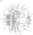
図1に本実施例におけるスクロール式流体機械の断面図を示す。図2はスクロール式流体機械の中の特に旋回スクロール8と背面プレート12の断面図である。
FIG. 1 is a sectional view of a scroll type fluid machine in the present embodiment. FIG. 2 is a cross-sectional view of the
スクロール式圧縮機の構成について図1を用いて説明する。 The configuration of the scroll compressor will be described with reference to FIG.
ケーシング1は、筒状に形成されると共に、その内部に後述の駆動軸15を回転可能に支持している。 The casing 1 is formed in a cylindrical shape, and a drive shaft 15 described later is rotatably supported therein.
ケーシング1の開口側に設けられた固定スクロール2は、図1に示すように、軸線O−Oを中心として略円板状に形成された鏡板3と、該鏡板3の表面となる歯底面に軸方向に立設された渦巻状のラップ部4と、該ラップ部4を取囲んで鏡板3の外径側に設けられた筒状の外周壁部5と、鏡板3の背面に突設された複数の冷却フィン6とによって大略構成されている。
As shown in FIG. 1, the
ここで、ラップ部4は、例えば最内径端を巻始め端として、最外径端を巻終り端としたときに、内径側から外径側に向けて例えば3巻前,後の渦巻状に巻回されている。そして、ラップ部4の歯先面は、相手方となる旋回スクロール8の鏡板9の歯底面から一定の軸方向寸法だけ離間している。
Here, the wrap portion 4 has a spiral shape, for example, three turns before and after three turns from the inner diameter side to the outer diameter side when the outermost diameter end is the winding start end and the outermost diameter end is the winding end end, for example. It is wound. The tooth tip surface of the wrap portion 4 is separated from the tooth bottom surface of the end plate 9 of the
また、ラップ部4の歯先面には、ラップ部4の巻回方向に沿ってシール溝4Aが設けられ、該シール溝4A内には、旋回スクロール8の鏡板9に摺接するシール部材としてのチップシール7が設けられている。さらに、外周壁部5は、略円形状をなして固定スクロール2の端面に開口している。そして、外周壁部5は、旋回スクロール8のラップ部10との干渉を避けるため、ラップ部10の外径側に配置されている。
Further, a
ケーシング1内に旋回可能に設けられた旋回スクロール8は、固定スクロール2の鏡板3と対向して配置された略円板状の鏡板9と、該鏡板9の表面となる歯底面に立設された渦巻状のラップ部10と、鏡板9の背面に突設された複数の冷却フィン11とによって大略構成されている。また、該冷却フィン11の先端側に位置して旋回スクロール8と駆動軸15とを接続する背面プレート12が設けられている。
The
ここで、ラップ部10は、固定スクロール2のラップ部4とほぼ同様に、例えば3巻前後の渦巻状をなしている。そして、ラップ部10の歯先面は、相手方となる固定スクロール2の鏡板3の歯底面から一定の軸方向寸法だけ離間している。また、ラップ部10の歯先面には、ラップ部10の巻回方向に沿ってシール溝10Aが設けられ、該シール溝10A内には、固定スクロール2の鏡板3に摺接するシール部材としてのチップシール13が設けられている。
Here, the wrap portion 10 has, for example, a spiral shape of about 3 turns, substantially the same as the wrap portion 4 of the
また、背面プレート12の中央側には、旋回軸受14a等を介して駆動軸15のクランク部15Aと回転可能に連結される筒状のボス部14が一体形成されている。このとき、駆動軸15の一端側には、ケーシング1の外部に位置してプーリ15Bが設けられ、このプーリ15Bは、例えば駆動源としての電動モータの出力側にベルト(いずれも図示せず)等を介して連結されている。これにより、駆動軸15は、電動モータ等によって回転駆動し、固定スクロール2に対して旋回スクロール8を旋回運動させる。
A
また、プーリ15Bにはボルト等を用いて冷却ファン16が取付けられ、該冷却ファン16は、ファンケーシング17内で冷却風を発生させる。これにより冷却ファン16は、冷却風をファンケーシング17内のダクト等に沿ってケーシング1の内部や各スクロール2,8の背面側に送風し、ケーシング1、固定スクロール2、旋回スクロール8等を冷却する。
A cooling fan 16 is attached to the pulley 15B using bolts or the like, and the cooling fan 16 generates cooling air in the fan casing 17. As a result, the cooling fan 16 blows cooling air along the ducts in the fan casing 17 to the inside of the casing 1 and the back side of the
さらに、背面プレート12の外径側とケーシング1との間には、旋回スクロール8の自転を防止する自転防止機構としての補助クランク18が例えば3個(1個のみ図示)設けられている。
Further, between the outer diameter side of the
固定スクロール2と旋回スクロール8との間に設けられた複数の圧縮室19は、ラップ部4,10の間に位置して外径側から内径側にわたって順次形成され、チップシール7,13によって気密に保持されている。そして、各圧縮室19は、旋回スクロール8が順方向に旋回運動するときに、ラップ部4,10の外径側から内径側に向けて移動しつつ、これらの間で連続的に縮小される。
A plurality of compression chambers 19 provided between the
これにより、各圧縮室19のうち最外径側に位置する圧縮室19Aには、後述する吸込口20から外部の空気が吸込まれ、この空気は最内径側に位置する圧縮室19Bに達するまでに圧縮されて圧縮空気となる。そして、この圧縮空気は吐出口22から吐出され、外部の貯留タンク(図示せず)に貯えられる。 Thereby, outside air is sucked into the compression chamber 19A located on the outermost diameter side of each compression chamber 19 from a suction port 20 described later until the air reaches the compression chamber 19B located on the innermost diameter side. To be compressed air. The compressed air is discharged from the discharge port 22 and stored in an external storage tank (not shown).
固定スクロール2の外径側に設けられた吸込口20は、鏡板3の外径側から外周壁部5にかけて開口し、最外径側に位置する圧縮室19Aに連通している。また、吸込口20は、固定スクロール2の鏡板3のうち旋回スクロール8のラップ部10の外径側に位置して、チップシール13が摺接しない範囲(非摺動領域)に開口している。そして、吸込口20は、例えば大気圧の空気を吸込フィルタ21を通じて最外径側に位置する圧縮室19A内に吸込むものである。
A suction port 20 provided on the outer diameter side of the
なお、吸込口20は、加圧された空気を吸込む構成としてもよい。この場合、吸込フィルタ21を取外して、加圧空気が供給される配管に吸込口20を接続する構成としてもよい。 The suction port 20 may be configured to suck in pressurized air. In this case, it is good also as a structure which removes the suction filter 21 and connects the suction inlet 20 to piping to which pressurized air is supplied.
固定スクロール2の鏡板3の内径側(中心側)に設けられた吐出口22は、最内径側に位置する圧縮室19Bに連通し、この圧縮室19B内の圧縮空気を外部に吐出させるものである。
A discharge port 22 provided on the inner diameter side (center side) of the end plate 3 of the
ラップ部4より外周側に位置するフランジ24は、固定スクロール2をケーシング1に固定するものである。
A
旋回スクロール8の鏡板9と対面する固定スクロール2の端面に設けられたフェイスシール溝25は、外周壁部5の外径側に位置し、外周壁部5を取囲む円環状に形成されている。また、フェイスシール溝25内には円環状のフェイスシール26が取付けられている。そして、フェイスシール26は、固定スクロール2の端面と旋回スクロール8の鏡板9との間を気密にシールし、これらの間から外周壁部5内に吸込んだ空気が漏れるのを防止している。
The face seal groove 25 provided on the end surface of the fixed
固定スクロール2のラップ部4の位置決めに関する構成を図1を用いて説明する。固定スクロール2は、そのラップ部4に対して高精度な複数の位置決め穴34がフランジ24部に設けられている。位置決め穴34は、ケーシング1のフランジ1aに対応する高精度な位置決め穴37と、位置決めピン35によって位置決めされている。位置決め穴37はケーシング1の主軸15を保持するための主軸受36のハウジング1bに対して高精度に設けられており、主軸15の径方向中心位置と、固定スクロールのラップ部4の径方向の位置決めを高精度に行うことができる。
A configuration relating to the positioning of the lap portion 4 of the fixed
旋回スクロール8のラップ部10の位置決めに関する構成を図2を用いて説明する。旋回スクロール8と駆動軸15との間に設けられ、旋回スクロール8と駆動軸15とを接続する背面プレート12には、旋回スクロール8に作用する圧縮荷重あるいは遠心力等を受けるため、複数の補助クランク軸受18aと旋回軸受14aを保持するための軸受ハウジング14b、18bを設けてある。さらに背面プレート12中心には軸受ハウジング14b、18bと同時(同工程)加工した精度の良い位置合わせ孔としての貫通孔12aを設けてある。なお、加工を容易にするため、位置合わせ孔は貫通孔12aとして貫通させてある。貫通孔12aは位置合わせの精度を上げるため、少なくとも駆動軸15(のクランク部15Aの外周面)よりは内側に設けられている。一方、旋回スクロール8の鏡板9、ラップ部10、冷却フィン11によって構成される旋回スクロール8のラップ部材8cのラップ中心にはラップ加工と同時(同工程)加工した精度の良い位置合わせ孔としての貫通孔8aを設けてあり、両者はそれぞれの貫通孔12a、8aを精度の良い位置合わせピン29によって位置決めした後、複数のボルト31で締結されている。
A configuration relating to the positioning of the wrap portion 10 of the
位置合わせピン29は貫通孔12a、8aに対して圧入で挿入してあり、位置ズレが発生しないように設定してある。また、位置合わせピン29には、ネジ溝(または突起)を設けないことにより、位置合わせの精度を向上させている。さらに、旋回軸受内のグリース漏れを確実に防止するためには、位置合わせピン29と貫通孔12a、8aとの微小隙間(表面粗さレベル)には接着剤等のシール剤を塗布しても良い。
The
ここで、特許文献1においては、旋回スクロールのラップ部材と背面プレートとの位置決め締結には貫通孔と平行ピンを用いている。しかし、平行ピンは位置合わせ精度には優れているが、封止機能が高くないことが考慮されていなかった。また、貫通孔は、旋回スクロールの中心側に設けられており、旋回スクロールの中心側の圧縮室は圧力が高くなるため、流体機械、特に圧縮機として使用する場合には貫通孔から流体が漏れやすくなり、圧縮効率を向上できなかった。 Here, in Patent Document 1, a through hole and a parallel pin are used for positioning and fastening between the wrap member of the orbiting scroll and the back plate. However, although the parallel pin is excellent in alignment accuracy, it has not been considered that the sealing function is not high. In addition, the through hole is provided at the center side of the orbiting scroll, and the pressure in the compression chamber at the center side of the orbiting scroll is high, so that fluid leaks from the through hole when used as a fluid machine, particularly as a compressor. It became easier and compression efficiency could not be improved.
そこで、本実施例では、図2に示すとおり、位置合わせは位置合わせに適した位置合わせピン29によって行い、旋回スクロール8側の貫通孔8aに位置合わせピン29よりも軸方向旋回スクロール8側に位置合わせピン29とは別部材の封止部材(シール部材)30を設け、精度のよい位置決めを行えるようにしつつ、圧縮流体のラップ外への漏れを防止している。なお、封止部材30と貫通孔8aとの間に接着剤等のシール剤を充填することによりさらにシール性を向上させることができる。
Therefore, in this embodiment, as shown in FIG. 2, the alignment is performed by the
ここで、位置合わせピン29の径よりも封止部材30の径を大きくし、それに伴い、旋回スクロール8側に設けた貫通孔8aの封止部材30が入る部分の径を位置合わせピン29が入る部分の径よりも大きくしてもよい。このようにすることで、封止部材30を深く挿入しすぎて位置合わせピン29を押し出してしまうことを防止することができる。また、封止部材30にネジ溝(または突起)を設け、貫通孔8aの封止部材30が入る部分に封止部材30のネジ溝(または突起)に対応するネジ溝(または突起)32を設けてもよい。これにより、封止部材30と貫通孔8aとをネジにより強く締結することができ、シール性を向上させることができる。さらに、封止部材30にシール材を塗布あるいは巻きつけて挿入してもよい。これにより、ネジ溝が形成された封止部材30とメネジ32との隙間をシール材にて封止することができシール性を向上させることができる。
Here, the diameter of the sealing
なお、旋回スクロール8のラップ10と、背面プレート12に設けた補助クランク軸受18aとの回転ズレに関しては、背面プレート12側には駆動軸15よりも径方向外側に回転位置決め用の貫通孔(図示せず)を設け、旋回スクロール8には、その位置に対応した穴(図示せず)を設け、それぞれの穴に対してある一定の隙間(ガタ)を有するピン (図示せず)等にて一時的に位置決めし、両者をボルト31等で締結した後に取り外している。ここで、回転位置決め用のピンは、部材に接着等により挿入したままでもよい
以上より本実施例によれば、旋回スクロール8のラップ部材8cと背面プレート12、即ちラップ部10(渦巻き)と軸受14a、18aとを高精度に位置決めすることが可能であり、かつラップ部材8cには貫通孔8aに封止部材30を設けてあるため圧縮流体の漏れを防止でき、圧縮効率と信頼性の向上を図ることができる
As for the rotational displacement between the wrap 10 of the
本発明の実施例2を図3を用いて説明する。実施例1と同一の構成については同一の符号を付し、その説明を省略する。本実施例は、封止部材30の先端(駆動軸15側)に先端(駆動軸15側)に向けて径が小さくなるようにテーパ部33を設けたことが特徴である。封止部材30が挿入されるラップ部材8cの貫通孔8aのテーパ部33と接触する部分(ネジ溝32よりも駆動軸15側)も駆動軸15側に向けて径が小さくなるようにテーパ上に形成した。これにより、封止部材30を締め込んだ際に封止部材30と貫通孔8aのテーパ面どうしが密着してシールすることができる。
A second embodiment of the present invention will be described with reference to FIG. The same components as those in the first embodiment are denoted by the same reference numerals, and description thereof is omitted. The present embodiment is characterized in that a tapered
本実施例によれば、実施例1よりも密着面積を増加することができるため、シール性をさらに向上させることができる。また、一般的に使用される止めネジ(とがり先)といった汎用部品が簡単に使用できる。 According to the present embodiment, since the adhesion area can be increased as compared with the first embodiment, the sealing performance can be further improved. Moreover, general-purpose parts such as commonly used set screws (points) can be used easily.
本発明の実施例3を図4を用いて説明する。実施例1、2と同一の構成については同一の符号を付し、その説明を省略する。本実施例は、封止部材30の先端(圧縮室19側)に先端(圧縮室19側)に向けて径が大きくなるようなテーパ部33を設けたことが特徴である。封止部材30が挿入されるラップ部材8cの貫通孔8aのテーパ部33と接触する部分(ネジ溝32よりも駆動軸15側)も圧縮室19側に向けて径が大きくなるようにテーパ上に形成した。
A third embodiment of the present invention will be described with reference to FIG. The same components as those in the first and second embodiments are denoted by the same reference numerals, and the description thereof is omitted. The present embodiment is characterized in that a tapered
本実施例によれば、テーパ面どうしの密着面積を広く取ることが可能であり、シール性をさらに向上することができる。また、一般的に使用される皿ボルトや皿ネジといった汎用部品を使用できる。 According to the present embodiment, it is possible to increase the contact area between the tapered surfaces, and the sealing performance can be further improved. Moreover, general-purpose parts such as generally used countersunk bolts and countersunk screws can be used.
本発明の実施例4を図5、6を用いて説明する。実施例1−3と同一の構成については同一の符号を付し、その説明を省略する。 A fourth embodiment of the present invention will be described with reference to FIGS. The same components as those in Example 1-3 are denoted by the same reference numerals, and the description thereof is omitted.
本実施例は、実施例1―3における封止部材30と、位置合わせピン29とを一体化したもことが特徴である。実施例1−3と同様に封止部材30に対応する部分(圧縮室19側)にはネジ溝または突起を設け、位置合わせピン29に対応する部分(駆動軸15側)にはネジ溝または突起を設けていない。
The present embodiment is characterized in that the sealing
本実施例によれば、部品点数および組立て工数を低減できる。 According to the present embodiment, the number of parts and the number of assembly steps can be reduced.
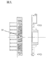
本発明の実施例5を図7、8を用いて説明する。実施例1−4と同一の構成については同一の符号を付し、その説明を省略する。 A fifth embodiment of the present invention will be described with reference to FIGS. The same reference numerals are given to the same configurations as those in Embodiment 1-4, and the description thereof is omitted.
図7、8は、封止部材30を取り付けた旋回スクロールラップ部材8cを駆動軸の長手方向から見た図である。本実施例は、旋回スクロール8のラップ部10の中心部8d(巻き始め)において、封止部材30を構成するために、中心部8dの内壁部8eを切り欠き部を形成したことが特徴である。
7 and 8 are views of the orbiting scroll wrap member 8c to which the sealing
本実施例では、旋回スクロール8の旋回半径が小さく、貫通孔8aおよび封止部材30(特に実施例3のテーパ部33)が構成し難い場合にラップ中心部8dの内壁部8eを切り欠くことにより、貫通孔8aおよび封止部材30の形成を容易にすることができる。
In this embodiment, when the turning radius of the
これまで説明してきた各実施例では、スクロール式流体機械としてスクロール式空気圧縮機に適用した場合を例に挙げて説明したが、本発明はこれに限らず、冷媒を圧縮する冷媒圧縮機、真空ポンプ等の他のスクロール式流体機械に適用してもよい。また、スクロール式流体機械を備えたタンク一体型パッケージ圧縮機や窒素ガス発生装置といったシステムに適用してもよい。 In each of the embodiments described so far, the case where the present invention is applied to a scroll type air compressor as a scroll type fluid machine has been described as an example. However, the present invention is not limited thereto, and a refrigerant compressor for compressing a refrigerant, a vacuum You may apply to other scroll type fluid machines, such as a pump. Moreover, you may apply to systems, such as a tank integrated package compressor provided with the scroll-type fluid machine, and a nitrogen gas generator.
これまで説明してきた実施例は、何れも本発明を実施するにあたっての具体化の一例を示したものに過ぎず、これらによって本発明の技術的範囲が限定的に解釈されない。すなわち、本発明はその技術思想、又はその主要な特徴から逸脱することなく、様々な形で実施することができる。また、実施例1乃至5を組み合わせることにより本発明を実施してもよい。 The embodiments described so far are merely examples of implementation in carrying out the present invention, and the technical scope of the present invention is not limitedly interpreted by these. That is, the present invention can be implemented in various forms without departing from the technical idea or the main features thereof. Further, the present invention may be implemented by combining Examples 1 to 5.
1 ケーシング
1a フランジ
1b ハウジング
2 固定スクロール
3,9 鏡板
4,10 ラップ部
5 外周壁部
6,11 冷却フィン
7,13 チップシール
8 旋回スクロール
8a 貫通孔
8c 旋回スクロールラップ部材
8d ラップ中心部
8e 切り欠き部
12 背面プレート
12a 貫通孔
14 ボス
14a 旋回軸受
14b 軸受ハウジング
15 駆動軸
16 冷却ファン
17 ファンケーシング
18 補助クランク
18a 補助クランク軸受
18b 軸受ハウジング
19 圧縮室
20 吸込口
21 吸込フィルタ
22 吐出口
23 固定スクロール傾斜部
24 フランジ
25 フェイスシール溝
26 フェイスシール
27 凹溝部
28 固定スクロール凸部
29 位置合わせピン
30 封止部材
31 ボルト
32 ネジ溝(または突起)
33 テーパ部
34 位置決め穴
35 ピン
36 主軸受
36a ハウジング
37 位置決め穴
DESCRIPTION OF SYMBOLS 1 Casing 1a
33
Claims (18)
前記固定スクロールに対向して設けられ、前記固定スクロールとの間に複数の圧縮室を形成して旋回運動する旋回スクロールと、
前記旋回クロールを駆動する駆動軸と、
前記駆動軸と前記旋回スクロールとの間に設けられる背面プレートとを備え、
前記旋回スクロールと前記背面プレートに位置合わせ孔を設け、前記位置合わせ孔に位置合わせを行う位置合わせピンと前記圧縮室をシールするシール部材を設け、前記位置合わせピンは前記位置合わせ孔に圧入されることを特徴とするスクロール式流体機械。 A revolving scroll that is provided facing the fixed scroll and the fixed scroll, and that orbits by forming a plurality of compression chambers between the fixed scroll,
A drive shaft for driving the turning crawl;
A back plate provided between the drive shaft and the orbiting scroll,
Said orbiting scroll and said rear plate to the positioning hole is provided, a seal member for sealing the compression chamber with the alignment pins for aligning the alignment holes provided, said alignment pin pressure input to said alignment holes Scroll type fluid machine characterized by being made.
前記固定スクロールに対向して設けられ、前記固定スクロールとの間に複数の圧縮室を形成して旋回運動する旋回スクロールと、
前記旋回クロールを駆動する駆動軸と、
前記駆動軸と前記旋回スクロールとの間に設けられる背面プレートとを備え、
前記旋回スクロールと前記背面プレートに位置合わせ孔を設け、前記位置合わせ孔にネジ溝または突起が設けられていない位置合わせピンとネジ溝または突起が設けられたシール部材を設け、前記位置合わせピンは前記位置合わせ孔に圧入されることを特徴とするスクロール式流体機械。 A revolving scroll that is provided facing the fixed scroll and the fixed scroll, and that orbits by forming a plurality of compression chambers between the fixed scroll,
A drive shaft for driving the turning crawl;
A back plate provided between the drive shaft and the orbiting scroll,
An alignment hole is provided in the orbiting scroll and the back plate, an alignment pin not provided with a screw groove or a protrusion in the alignment hole and a seal member provided with a screw groove or a protrusion are provided, and the alignment pin is scroll fluid machine characterized in that it is pressure input to the position-aligning hole.
Priority Applications (5)
| Application Number | Priority Date | Filing Date | Title |
|---|---|---|---|
| JP2012239770A JP5998012B2 (en) | 2012-10-31 | 2012-10-31 | Scroll type fluid machine |
| EP13003766.6A EP2728113A3 (en) | 2012-10-31 | 2013-07-29 | Scroll fluid machine |
| US13/953,910 US9133846B2 (en) | 2012-10-31 | 2013-07-30 | Scroll fluid machine having a sealed compression chamber |
| KR20130091001A KR20140055951A (en) | 2012-10-31 | 2013-07-31 | Scroll type fluid machine |
| CN201310331700.4A CN103790825A (en) | 2012-10-31 | 2013-08-01 | Scroll fluid machine |
Applications Claiming Priority (1)
| Application Number | Priority Date | Filing Date | Title |
|---|---|---|---|
| JP2012239770A JP5998012B2 (en) | 2012-10-31 | 2012-10-31 | Scroll type fluid machine |
Publications (3)
| Publication Number | Publication Date |
|---|---|
| JP2014088839A JP2014088839A (en) | 2014-05-15 |
| JP2014088839A5 JP2014088839A5 (en) | 2015-09-17 |
| JP5998012B2 true JP5998012B2 (en) | 2016-09-28 |
Family
ID=48900738
Family Applications (1)
| Application Number | Title | Priority Date | Filing Date |
|---|---|---|---|
| JP2012239770A Active JP5998012B2 (en) | 2012-10-31 | 2012-10-31 | Scroll type fluid machine |
Country Status (5)
| Country | Link |
|---|---|
| US (1) | US9133846B2 (en) |
| EP (1) | EP2728113A3 (en) |
| JP (1) | JP5998012B2 (en) |
| KR (1) | KR20140055951A (en) |
| CN (1) | CN103790825A (en) |
Families Citing this family (8)
| Publication number | Priority date | Publication date | Assignee | Title |
|---|---|---|---|---|
| CN104061160B (en) * | 2014-06-24 | 2016-01-20 | 广东广顺新能源动力科技有限公司 | A kind of oil-free vortex formula compressor assembly |
| WO2016038694A1 (en) * | 2014-09-10 | 2016-03-17 | 株式会社日立産機システム | Scroll fluid machine |
| CN106122011B (en) * | 2016-04-25 | 2018-09-14 | 徐道敏 | A kind of screw compressor |
| CN109312738B (en) * | 2016-07-07 | 2019-11-26 | 株式会社日立产机系统 | Convolute-hydrodynamic mechanics |
| JP1574166S (en) * | 2016-08-31 | 2020-04-06 | ||
| JP1574165S (en) * | 2016-08-31 | 2020-04-06 | ||
| US20200088193A1 (en) * | 2017-08-25 | 2020-03-19 | Mitsubishi Heavy Industries, Ltd. | Co-rotating scroll compressor |
| US10767688B2 (en) * | 2018-03-27 | 2020-09-08 | Roller Bearing Company Of America, Inc. | Bearing system for an articulating motor device |
Family Cites Families (16)
| Publication number | Priority date | Publication date | Assignee | Title |
|---|---|---|---|---|
| JPH02124288U (en) * | 1989-03-22 | 1990-10-12 | ||
| US5106279A (en) | 1991-02-04 | 1992-04-21 | Tecumseh Products Company | Orbiting scroll member assembly |
| JPH06341384A (en) * | 1993-06-02 | 1994-12-13 | Kobe Steel Ltd | Oil-free scroll compressor |
| JP3653128B2 (en) * | 1995-09-01 | 2005-05-25 | 株式会社日立製作所 | Scroll type fluid machine |
| JP3424881B2 (en) * | 1995-09-01 | 2003-07-07 | トキコ株式会社 | Scroll type fluid machine |
| JP2002213376A (en) * | 2001-01-19 | 2002-07-31 | Anest Iwata Corp | Scroll fluid machine |
| JP4824231B2 (en) * | 2001-09-28 | 2011-11-30 | 株式会社日立産機システム | Assembling method of scroll type fluid machine |
| JP4510495B2 (en) * | 2004-03-30 | 2010-07-21 | アネスト岩田株式会社 | Scroll fluid machinery |
| JP2005337189A (en) | 2004-05-31 | 2005-12-08 | Anest Iwata Corp | Method for manufacturing revolving scroll of scroll fluid machine |
| JP4303182B2 (en) * | 2004-09-30 | 2009-07-29 | 株式会社日立製作所 | Scroll type fluid machine |
| JP4629546B2 (en) * | 2005-09-30 | 2011-02-09 | アネスト岩田株式会社 | Scroll fluid machinery |
| JP4920244B2 (en) * | 2005-11-08 | 2012-04-18 | アネスト岩田株式会社 | Scroll fluid machinery |
| JP2007162602A (en) | 2005-12-15 | 2007-06-28 | Mitsubishi Electric Corp | Scroll compressor |
| JP5048303B2 (en) * | 2006-10-31 | 2012-10-17 | 株式会社日立産機システム | Scroll type fluid machine |
| US7901194B2 (en) * | 2008-04-09 | 2011-03-08 | Hamilton Sundstrand Corporation | Shaft coupling for scroll compressor |
| JP2011038492A (en) | 2009-08-18 | 2011-02-24 | Honda Motor Co Ltd | Scroll compressor |
-
2012
- 2012-10-31 JP JP2012239770A patent/JP5998012B2/en active Active
-
2013
- 2013-07-29 EP EP13003766.6A patent/EP2728113A3/en not_active Withdrawn
- 2013-07-30 US US13/953,910 patent/US9133846B2/en active Active
- 2013-07-31 KR KR20130091001A patent/KR20140055951A/en active Search and Examination
- 2013-08-01 CN CN201310331700.4A patent/CN103790825A/en active Pending
Also Published As
| Publication number | Publication date |
|---|---|
| CN103790825A (en) | 2014-05-14 |
| EP2728113A3 (en) | 2018-03-07 |
| US20140119970A1 (en) | 2014-05-01 |
| EP2728113A2 (en) | 2014-05-07 |
| KR20140055951A (en) | 2014-05-09 |
| JP2014088839A (en) | 2014-05-15 |
| US9133846B2 (en) | 2015-09-15 |
Similar Documents
| Publication | Publication Date | Title |
|---|---|---|
| JP5998012B2 (en) | Scroll type fluid machine | |
| US7758326B2 (en) | Scroll fluid machine | |
| KR100877017B1 (en) | Fluid apparatus | |
| JP2008215108A (en) | Seal device and scroll type fluid machine | |
| WO2014155546A1 (en) | Scroll compressor | |
| US8734142B2 (en) | Rotation preventing member of a scroll compressor | |
| US8714950B2 (en) | Scroll compressor having tip seals of different lengths having different thickness or widths | |
| US10844719B2 (en) | Scroll fluid machine including a pair of fixed scrolls and an orbiting scroll | |
| WO2022030185A1 (en) | Compressor and method for manufacturing compressor | |
| KR101886668B1 (en) | Scroll fluid machine | |
| WO2018131088A1 (en) | Compressor | |
| JP2018071359A (en) | Scroll fluid machine | |
| US10590769B2 (en) | Scroll fluid machine | |
| WO2024042984A1 (en) | Scroll compressor | |
| JP2013241854A (en) | Rotation preventing mechanism and scroll compressor using the same | |
| JP2005163687A (en) | Electric compressor and its manufacturing method | |
| JP2023077785A (en) | Motor compressor and manufacturing method | |
| JP2017198133A (en) | Scroll compressor | |
| KR20160089779A (en) | Scroll compressor | |
| JP2023140880A (en) | Root pump | |
| JP2005061304A (en) | Scroll type fluid machine | |
| WO2016088326A1 (en) | Cylinder rotary compressor | |
| JP2011185208A (en) | Scroll fluid machine and method of assembling the same | |
| JP2010248991A (en) | Sealed fluid machinery | |
| JP2006029252A (en) | Scroll compressor |
Legal Events
| Date | Code | Title | Description |
|---|---|---|---|
| A621 | Written request for application examination |
Free format text: JAPANESE INTERMEDIATE CODE: A621 Effective date: 20150116 |
|
| A521 | Written amendment |
Free format text: JAPANESE INTERMEDIATE CODE: A523 Effective date: 20150116 |
|
| A521 | Written amendment |
Free format text: JAPANESE INTERMEDIATE CODE: A523 Effective date: 20150730 |
|
| A977 | Report on retrieval |
Free format text: JAPANESE INTERMEDIATE CODE: A971007 Effective date: 20151218 |
|
| A131 | Notification of reasons for refusal |
Free format text: JAPANESE INTERMEDIATE CODE: A131 Effective date: 20160105 |
|
| A521 | Written amendment |
Free format text: JAPANESE INTERMEDIATE CODE: A523 Effective date: 20160222 |
|
| TRDD | Decision of grant or rejection written | ||
| A01 | Written decision to grant a patent or to grant a registration (utility model) |
Free format text: JAPANESE INTERMEDIATE CODE: A01 Effective date: 20160802 |
|
| A61 | First payment of annual fees (during grant procedure) |
Free format text: JAPANESE INTERMEDIATE CODE: A61 Effective date: 20160829 |
|
| R150 | Certificate of patent or registration of utility model |
Ref document number: 5998012 Country of ref document: JP Free format text: JAPANESE INTERMEDIATE CODE: R150 |