KR20140055951A - Scroll type fluid machine - Google Patents
Scroll type fluid machine Download PDFInfo
- Publication number
- KR20140055951A KR20140055951A KR20130091001A KR20130091001A KR20140055951A KR 20140055951 A KR20140055951 A KR 20140055951A KR 20130091001 A KR20130091001 A KR 20130091001A KR 20130091001 A KR20130091001 A KR 20130091001A KR 20140055951 A KR20140055951 A KR 20140055951A
- Authority
- KR
- South Korea
- Prior art keywords
- scroll
- orbiting scroll
- fluid machine
- machine according
- seal member
- Prior art date
Links
Images

Classifications
-
- F—MECHANICAL ENGINEERING; LIGHTING; HEATING; WEAPONS; BLASTING
- F04—POSITIVE - DISPLACEMENT MACHINES FOR LIQUIDS; PUMPS FOR LIQUIDS OR ELASTIC FLUIDS
- F04C—ROTARY-PISTON, OR OSCILLATING-PISTON, POSITIVE-DISPLACEMENT MACHINES FOR LIQUIDS; ROTARY-PISTON, OR OSCILLATING-PISTON, POSITIVE-DISPLACEMENT PUMPS
- F04C27/00—Sealing arrangements in rotary-piston pumps specially adapted for elastic fluids
-
- F—MECHANICAL ENGINEERING; LIGHTING; HEATING; WEAPONS; BLASTING
- F04—POSITIVE - DISPLACEMENT MACHINES FOR LIQUIDS; PUMPS FOR LIQUIDS OR ELASTIC FLUIDS
- F04C—ROTARY-PISTON, OR OSCILLATING-PISTON, POSITIVE-DISPLACEMENT MACHINES FOR LIQUIDS; ROTARY-PISTON, OR OSCILLATING-PISTON, POSITIVE-DISPLACEMENT PUMPS
- F04C29/00—Component parts, details or accessories of pumps or pumping installations, not provided for in groups F04C18/00 - F04C28/00
- F04C29/0021—Systems for the equilibration of forces acting on the pump
- F04C29/0028—Internal leakage control
-
- F—MECHANICAL ENGINEERING; LIGHTING; HEATING; WEAPONS; BLASTING
- F01—MACHINES OR ENGINES IN GENERAL; ENGINE PLANTS IN GENERAL; STEAM ENGINES
- F01C—ROTARY-PISTON OR OSCILLATING-PISTON MACHINES OR ENGINES
- F01C1/00—Rotary-piston machines or engines
- F01C1/02—Rotary-piston machines or engines of arcuate-engagement type, i.e. with circular translatory movement of co-operating members, each member having the same number of teeth or tooth-equivalents
- F01C1/0207—Rotary-piston machines or engines of arcuate-engagement type, i.e. with circular translatory movement of co-operating members, each member having the same number of teeth or tooth-equivalents both members having co-operating elements in spiral form
- F01C1/0215—Rotary-piston machines or engines of arcuate-engagement type, i.e. with circular translatory movement of co-operating members, each member having the same number of teeth or tooth-equivalents both members having co-operating elements in spiral form where only one member is moving
-
- F—MECHANICAL ENGINEERING; LIGHTING; HEATING; WEAPONS; BLASTING
- F04—POSITIVE - DISPLACEMENT MACHINES FOR LIQUIDS; PUMPS FOR LIQUIDS OR ELASTIC FLUIDS
- F04C—ROTARY-PISTON, OR OSCILLATING-PISTON, POSITIVE-DISPLACEMENT MACHINES FOR LIQUIDS; ROTARY-PISTON, OR OSCILLATING-PISTON, POSITIVE-DISPLACEMENT PUMPS
- F04C18/00—Rotary-piston pumps specially adapted for elastic fluids
- F04C18/02—Rotary-piston pumps specially adapted for elastic fluids of arcuate-engagement type, i.e. with circular translatory movement of co-operating members, each member having the same number of teeth or tooth-equivalents
- F04C18/0207—Rotary-piston pumps specially adapted for elastic fluids of arcuate-engagement type, i.e. with circular translatory movement of co-operating members, each member having the same number of teeth or tooth-equivalents both members having co-operating elements in spiral form
- F04C18/0215—Rotary-piston pumps specially adapted for elastic fluids of arcuate-engagement type, i.e. with circular translatory movement of co-operating members, each member having the same number of teeth or tooth-equivalents both members having co-operating elements in spiral form where only one member is moving
-
- F—MECHANICAL ENGINEERING; LIGHTING; HEATING; WEAPONS; BLASTING
- F04—POSITIVE - DISPLACEMENT MACHINES FOR LIQUIDS; PUMPS FOR LIQUIDS OR ELASTIC FLUIDS
- F04C—ROTARY-PISTON, OR OSCILLATING-PISTON, POSITIVE-DISPLACEMENT MACHINES FOR LIQUIDS; ROTARY-PISTON, OR OSCILLATING-PISTON, POSITIVE-DISPLACEMENT PUMPS
- F04C18/00—Rotary-piston pumps specially adapted for elastic fluids
- F04C18/02—Rotary-piston pumps specially adapted for elastic fluids of arcuate-engagement type, i.e. with circular translatory movement of co-operating members, each member having the same number of teeth or tooth-equivalents
- F04C18/0207—Rotary-piston pumps specially adapted for elastic fluids of arcuate-engagement type, i.e. with circular translatory movement of co-operating members, each member having the same number of teeth or tooth-equivalents both members having co-operating elements in spiral form
- F04C18/0246—Details concerning the involute wraps or their base, e.g. geometry
- F04C18/0253—Details concerning the base
Landscapes
- Engineering & Computer Science (AREA)
- Mechanical Engineering (AREA)
- General Engineering & Computer Science (AREA)
- Rotary Pumps (AREA)
Abstract
Description
본 발명은, 스크롤식 유체 기계에 관한 것이다The present invention relates to a scroll fluid machine
특허 문헌 1에는, 선회 스크롤 부재와 배면 플레이트의 양 부재에 관통 구멍을 형성하고, 양쪽 관통 구멍에 평행 핀을 삽입하여, 양자를 체결하는 스크롤식 유체 기계가 기재되어 있다.
특허 문헌 1에 기재된 스크롤식 유체 기계는, 평행 핀은 위치 정렬 정밀도에는 적합하지만, 압축 공기의 시일에는 적합하지 않은 것은 고려되어 있지 않았다. 그로 인해, 압축 유체의 시일이 불충분하여, 압축 효율을 향상시키기 위해서는 불충분했다. 또한, 위치 결정용의 평행핀과 관통 구멍의 간극으로부터 누설된 압축 유체는 고온이기 때문에, 베어링이나 그리스 등의 윤활유의 열열화나 그리스 누설을 억제할 수 없어, 신뢰성을 향상시키기 위해서는 불충분했다.In the scroll fluid machine disclosed in
상기 문제점을 감안하여, 본 발명은, 선회 스크롤 부재와 배면 플레이트를 고정밀도로 위치 결정하면서, 관통 구멍을 밀봉하는 부재를 설치함으로써, 압축 효율과 신뢰성을 향상시킨 스크롤식 유체 기계를 제공하는 것을 목적으로 한다.SUMMARY OF THE INVENTION In view of the above problems, it is an object of the present invention to provide a scroll fluid machine in which compression efficiency and reliability are improved by providing a member for sealing a through hole while positioning the orbiting scroll member and the back plate with high accuracy do.
상기 과제를 해결하기 위해서, 본 발명은, 고정 스크롤과 상기 고정 스크롤에 대향하여 설치되고, 상기 고정 스크롤과의 사이에 복수의 압축실을 형성하여 선회 운동하는 선회 스크롤과, 상기 선회 스크롤을 구동하는 구동축과, 상기 구동축과 상기 선회 스크롤 사이에 설치되는 배면 플레이트를 구비하고, 상기 선회 스크롤과 상기 배면 플레이트에 위치 정렬 구멍을 형성하여, 상기 위치 정렬 구멍에 위치 정렬을 행하는 위치 정렬 핀과 상기 압축실을 시일하는 시일 부재를 설치하는 것을 특징으로하는 스크롤식 유체 기계를 제공한다.According to an aspect of the present invention, there is provided a scroll compressor comprising: a fixed scroll; a orbiting scroll which is provided to face the fixed scroll and forms a plurality of compression chambers between the fixed scroll and the fixed scroll; And a rear plate provided between the driving shaft and the orbiting scroll and having a positioning hole formed in the orbiting scroll and the back plate to align the positioning hole with the positioning hole, And a seal member for sealing the seal member.
본 발명에 따르면, 선회 스크롤 부재와 배면 플레이트를 고정밀도로 위치 결정하면서, 관통 구멍을 밀봉하는 부재를 설치함으로써, 압축 효율과 신뢰성을 향상시킨 스크롤식 유체 기계를 제공할 수 있다.According to the present invention, it is possible to provide a scroll fluid machine in which compression efficiency and reliability are improved by providing a member for sealing the through hole while positioning the orbiting scroll member and the back plate with high accuracy.
도 1은 본 발명의 제1 실시예에 관한 스크롤식 유체 기계의 단면도.
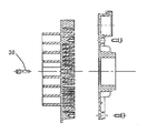
도 2는 본 발명의 제1 실시예에 관한 스크롤식 유체 기계의 부분 단면도.
도 3은 본 발명의 제2 실시예에 관한 스크롤식 유체 기계의 부분 단면도.
도 4는 본 발명의 제3 실시예에 관한 스크롤식 유체 기계의 부분 단면도.
도 5은 본 발명의 제4 실시예에 관한 스크롤식 유체 기계의 부분 단면도.
도 6은 본 발명의 제4 실시예에 관한 스크롤식 유체 기계의 부분 단면도.
도 7은 본 발명의 제5 실시예에 관한 선회 스크롤 랩의 정면도.
도 8은 본 발명의 제5 실시예에 관한 선회 스크롤 랩 중심부의 정면 확대도.1 is a sectional view of a scroll fluid machine according to a first embodiment of the present invention;
2 is a partial cross-sectional view of a scroll fluid machine according to a first embodiment of the present invention;
3 is a partial cross-sectional view of a scroll fluid machine according to a second embodiment of the present invention.
4 is a partial cross-sectional view of a scroll fluid machine according to a third embodiment of the present invention.
5 is a partial cross-sectional view of a scroll fluid machine according to a fourth embodiment of the present invention.
6 is a partial cross-sectional view of a scroll fluid machine according to a fourth embodiment of the present invention;
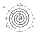
7 is a front view of the orbiting scroll wrap according to the fifth embodiment of the present invention.
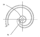
8 is a front enlarged view of a center portion of the orbiting scroll lap according to the fifth embodiment of the present invention.
이하, 본 발명의 실시예에 의한 스크롤식 유체 기계로서 스크롤식 공기 압축기를 예로 들어, 첨부 도면을 따라 상세하게 설명한다.BEST MODE FOR CARRYING OUT THE INVENTION Hereinafter, a scroll type air compressor as a scroll fluid machine according to an embodiment of the present invention will be described in detail with reference to the accompanying drawings.
[제1 실시예] [First Embodiment]
본 발명의 제1 실시예를 도 1, 2를 사용해서 설명한다.A first embodiment of the present invention will be described with reference to Figs. 1 and 2. Fig.
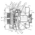
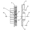
도 1에 본 실시예에 있어서의 스크롤식 유체 기계의 단면도를 나타낸다. 도 2는 스크롤식 유체 기계 중 특히 선회 스크롤(8)과 배면 플레이트(12)의 단면도이다.Fig. 1 shows a cross-sectional view of a scroll fluid machine in the present embodiment. Figure 2 is a cross-sectional view of the scroll fluid machine, especially the orbiting scroll (8) and the back plate (12).
스크롤식 압축기의 구성에 대해서 도 1을 사용해서 설명한다.The configuration of the scroll compressor will be described with reference to Fig.
케이싱(1)은, 통 형상으로 형성되는 동시에, 그 내부에 후술하는 구동축(15)을 회전 가능하게 지지하고 있다.The
케이싱(1)의 개구측에 설치된 고정 스크롤(2)은, 도 1에 나타낸 바와 같이, 축선 O-O를 중심으로 하여 대략 원판 형상으로 형성된 경판(3)과, 상기 경판(3)의 표면이 되는 치저면에 축 방향으로 세워 설치된 소용돌이 형상의 랩부(4)와, 상기 랩부(4)를 둘러싸 경판(3)의 외경측에 설치된 통 형상의 외주 벽부(5)와, 경판(3)의 배면에 돌출 설치된 복수의 냉각 핀(6)에 의해 대략 구성되어 있다.1, the
여기서, 랩부(4)는, 예를 들어 최내경 단부를 권취 개시 단부로 하고, 최외경 단부를 권취 종료 단부로 했을 때에, 내경측으로부터 외경측을 향해서 예를 들어 3권취 전, 후의 소용돌이 형상으로 권회되어 있다. 그리고, 랩부(4)의 치선면(齒先面)은, 상대방이 되는 선회 스크롤(8)의 경판(9)의 치저면(齒低面)으로부터 일정한 축 방향 치수만큼 이격되어 있다.Here, the lap portion 4 is formed into a spiral shape before and after, for example, three turns from the inner diameter side to the outer diameter side when the innermost end portion is the winding start end portion and the outermost diameter end portion is the winding end portion . The tooth surface of the lap portion 4 is spaced from the tooth bottom surface (bottom surface) of the
또한, 랩부(4)의 치선면에는, 랩부(4)의 권회 방향을 따라 시일 홈(4A)이 설치되고, 상기 시일 홈(4A) 내에는, 선회 스크롤(8)의 경판(9)에 미끄럼 접촉하는 시일 부재로서의 팁 시일(7)이 설치되어 있다. 또한, 외주 벽부(5)는, 대략 원형 형상을 이루고 고정 스크롤(2)의 단부면에 개방되어 있다. 그리고, 외주 벽부(5)는, 선회 스크롤(8)의 랩부(10)와의 간섭을 피하기 위해서, 랩부(10)의 외경측에 배치되어 있다.A
케이싱(1) 내에 선회 가능하게 설치된 선회 스크롤(8)은, 고정 스크롤(2)의 경판(3)과 대향하여 배치된 대략 원판 형상의 경판(9)과, 상기 경판(9)의 표면이 되는 치저면에 세워 설치된 소용돌이 형상의 랩부(10)와, 경판(9)의 배면에 돌출 설치된 복수의 냉각 핀(11)에 의해 대략 구성되어 있다. 또한, 상기 냉각 핀(11)의 선단측에 위치하여 선회 스크롤(8)과 구동축(15)을 접속하는 배면 플레이트(12)가 설치되어 있다.The orbiting scroll 8 pivotably installed in the
여기서, 랩부(10)는, 고정 스크롤(2)의 랩부(4)와 거의 동일하게, 예를 들어 3권취 전후의 소용돌이 형상을 이루고 있다. 그리고, 랩부(10)의 치선면은, 상대방이 되는 고정 스크롤(2)의 경판(3)의 치저면으로부터 일정한 축 방향 치수만 큼 이격되어 있다. 또한, 랩부(10)의 치선면에는, 랩부(10)의 권회 방향을 따라 시일 홈(10A)이 설치되고, 상기 시일 홈(10A) 내에는, 고정 스크롤(2)의 경판(3)에 미끄럼 접촉하는 시일 부재로서의 팁 시일(13)이 설치되어 있다.Here, the lap portion 10 has a spiral shape, for example, before and after three turns, in substantially the same manner as the lap portion 4 of the
또한, 배면 플레이트(12)의 중앙측에는, 선회 베어링(14a) 등을 통해서 구동축(15)의 크랭크부(15A)와 회전 가능하게 연결되는 통 형상의 보스부(14)가 일체 로 형성되어 있다. 이때, 구동축(15)의 일단부측에는, 케이싱(1)의 외부에 위치하여 풀리(15B)가 설치되고, 이 풀리(15B)는, 예를 들어 구동원으로서의 전동 모터의 출력측으로 벨트(모두 도시 생략) 등을 통해서 연결되어 있다. 이에 의해, 구동축(15)은, 전동 모터 등에 의해 회전 구동하고, 고정 스크롤(2)에 대하여 선회 스크롤(8)을 선회 운동시킨다.A
또한, 풀리(15B)에는 볼트 등을 사용해서 냉각 팬(16)이 설치되고, 상기 냉각 팬(16)은, 팬 케이싱(17) 내에서 냉각풍을 발생시킨다. 이에 의해 냉각 팬(16)은, 냉각풍을 팬 케이싱(17) 내의 덕트 등을 따라 케이싱(1)의 내부나 각 스크롤(2, 8)의 배면측으로 송풍하여, 케이싱(1), 고정 스크롤(2), 선회 스크롤(8) 등을 냉각한다.The
또한, 배면 플레이트(12)의 외경측과 케이싱(1) 사이에는, 선회 스크롤(8)의 자전을 방지하는 자전 방지 기구로서의 보조 크랭크(18)가 예를 들어 3개(1개만 도시) 설치되어 있다.Between the outer diameter side of the
고정 스크롤(2)과 선회 스크롤(8) 사이에 설치된 복수의 압축실(19)은, 랩부(4, 10)의 사이에 위치하여 외경측으로부터 내경측에 걸쳐 순차 형성되고, 팁 시일(7, 13)에 의해 기밀하게 보유 지지되어 있다. 그리고, 각 압축실(19)은, 선회 스크롤(8)이 순방향으로 선회 운동할 때에, 랩부(4, 10)의 외경측으로부터 내경측을 향해서 이동하면서, 이들 사이에서 연속적으로 축소된다.A plurality of
이에 의해, 각 압축실(19) 중 최외경측에 위치하는 압축실(19A)에는, 후술하는 흡입구(20)로부터 외부의 공기가 흡입되고, 이 공기는 최내경측에 위치하는 압축실(19B)에 도달할 때까지 압축되어 압축 공기가 된다. 그리고, 이 압축 공기는 토출구(22)로부터 토출되어, 외부의 저류 탱크(도시 생략)에 저장된다.Thus, outside air is sucked into the compression chamber 19A located on the outermost side among the
고정 스크롤(2)의 외경측에 설치된 흡입구(20)는, 경판(3)의 외경측으로부터 외주 벽부(5)에 걸쳐서 개방하고, 최외경측에 위치하는 압축실(19A)에 연통하고 있다. 또한, 흡입구(20)는, 고정 스크롤(2)의 경판(3) 중 선회 스크롤(8)의 랩부(10)의 외경측에 위치하여, 팁 시일(13)이 미끄럼 접촉하지 않는 범위(비 미끄럼 이동 영역)에 개방되어 있다. 그리고, 흡입구(20)는, 예를 들어 대기압의 공기를 흡입 필터(21)를 통해서 최외경측에 위치하는 압축실(19A) 내에 흡입하는 것이다.The
또한, 흡입구(20)는, 가압된 공기를 흡입하는 구성으로 해도 된다. 이 경우, 흡입 필터(21)를 제거하여, 가압 공기가 공급되는 배관에 흡입구(20)를 접속하는 구성으로 해도 된다.Further, the
고정 스크롤(2)의 경판(3)의 내경측(중심측)에 설치된 토출구(22)는, 최내경측에 위치하는 압축실(19B)에 연통하고, 이 압축실(19B) 내의 압축 공기를 외부로 토출시키는 것이다.The
랩부(4)보다 외주측에 위치하는 플랜지(24)는, 고정 스크롤(2)을 케이싱(1)에 고정하는 것이다.The
선회 스크롤(8)의 경판(9)과 대면하는 고정 스크롤(2)의 단부면에 설치된 페이스 시일 홈(25)은, 외주 벽부(5)의 외경측에 위치하고, 외주 벽부(5)를 둘러싸는 원환상으로 형성되어 있다. 또한, 페이스 시일 홈(25) 내에는 원환상의 페이스 시일(26)이 설치되어 있다. 그리고, 페이스 시일(26)은, 고정 스크롤(2)의 단부면과 선회 스크롤(8)의 경판(9) 사이를 기밀하게 시일하여, 이들 사이로부터 외주 벽부(5) 내로 흡입한 공기가 누설되는 것을 방지하고 있다.The
고정 스크롤(2)의 랩부(4)의 위치 결정에 관한 구성을 도 1를 사용해서 설명한다. 고정 스크롤(2)은, 그 랩부(4)에 대하여 고정밀도인 복수의 위치 결정 구멍(34)이 플랜지(24)부에 형성되어 있다. 위치 결정 구멍(34)은, 케이싱(1)의 플랜지(1a)에 대응하는 고정밀도인 위치 결정 구멍(37)과, 위치 결정 핀(35)에 의해 위치 결정되어 있다. 위치 결정 구멍(37)은 케이싱(1)의 주축(15)을 보유 지지하기 위한 주베어링(36)의 하우징(1b)에 대하여 고정밀도로 설치되어 있고, 주축(15)의 직경 방향 중심 위치와, 고정 스크롤의 랩부(4)의 직경 방향의 위치 결정을 고정밀도로 행할 수 있다.The arrangement relating to the positioning of the lap portion 4 of the
선회 스크롤(8)의 랩부(10)의 위치 결정에 관한 구성을 도 2를 사용해서 설명한다. 선회 스크롤(8)과 구동축(15) 사이에 설치되고, 선회 스크롤(8)과 구동축(15)을 접속하는 배면 플레이트(12)에는, 선회 스크롤(8)에 작용하는 압축 하중 혹은 원심력 등을 받기 때문에, 복수의 보조 크랭크 베어링(18a)과 선회 베어링(14a)을 보유 지지하기 위한 베어링 하우징(14b), (18b)을 설치하고 있다. 또한 배면 플레이트(12) 중심에는 베어링 하우징(14b), (18b)과 동시(동공정) 가공한 정밀도가 좋은 위치 정렬 구멍으로서의 관통 구멍(12a)을 형성하고 있다. 또한, 가공을 용히하게 하기 위해서, 위치 정렬 구멍은 관통 구멍(12a)으로서 관통시키고 있다. 관통 구멍(12a)은 위치 정렬의 정밀도를 높이기 위해서, 적어도 구동축(15)[의 크랭크부(15A)의 외주면]보다는 내측에 설치되어 있다. 한편, 선회 스크롤(8)의 경판(9), 랩부(10), 냉각 핀(11)에 의해 구성되는 선회 스크롤(8)의 랩 부재(8c)의 랩 중심에는 랩 가공과 동시(동공정) 가공한 정밀도가 좋은 위치 정렬 구멍으로서의 관통 구멍(8a)을 형성하고 있고, 양자는 각각의 관통 구멍(12a), (8a)을 정밀도가 좋은 위치 정렬 핀(29)에 의해 위치 결정한 후, 복수의 볼트(31)로 체결되어 있다.A configuration relating to the positioning of the wrap portion 10 of the orbiting scroll 8 will be described with reference to Fig. The
위치 정렬 핀(29)은 관통 구멍(12a), (8a)에 대하여 압입에 의해 삽입해 있어, 위치 어긋남이 발생하지 않도록 설정되어 있다. 또한, 위치 정렬 핀(29)에는, 나사 홈(또는 돌기)을 설치하지 않음으로써, 위치 정렬의 정밀도를 향상시키고 있다. 또한, 선회 베어링 내의 그리스 누설을 확실하게 방지하기 위해서는, 위치 정렬 핀(29)과 관통 구멍(12a), (8a)의 미소한 간극(표면 거칠기 레벨)에는 접착제 등의 시일제를 도포해도 된다.The
여기서, 특허 문헌 1에 있어서는, 선회 스크롤의 랩 부재와 배면 플레이트의 위치 결정 체결에는 관통 구멍과 평행 핀을 사용하고 있다. 그러나, 평행 핀은 위치 정렬 정밀도에는 우수하지만, 밀봉 기능이 높지 않은 것이 고려되어 있지 않았다. 또한, 관통 구멍은, 선회 스크롤의 중심측에 형성되어 있고, 선회 스크롤의 중심측의 압축실은 압력이 높아지기 때문에, 유체 기계, 특히 압축기로서 사용하는 경우에는 관통 구멍으로부터 유체가 누설되기 쉬워, 압축 효율을 향상시킬 수 없었다.Here, in
따라서, 본 실시예에서는, 도 2에 나타낸 바와 같이, 위치 정렬은 위치 정렬에 적합한 위치 정렬 핀(29)에 의해 행하고, 선회 스크롤(8)측의 관통 구멍(8a)에 위치 정렬 핀(29)보다도 축 방향 선회 스크롤(8)측에 위치 정렬 핀(29)과는 별도의 부재의 밀봉 부재(시일 부재)(30)를 설치하여, 정밀도가 좋은 위치 결정을 행할 수 있도록 하면서, 압축 유체의 랩 이외에의 누설을 방지하고 있다. 또한, 밀봉 부재(30)와 관통 구멍(8a) 사이에 접착제 등의 시일제를 충전함으로써 더욱 시일성을 향상시킬 수 있다.2, positioning is performed by an
여기서, 위치 정렬 핀(29)의 직경보다도 밀봉 부재(30)의 직경을 크게 하고, 그에 수반하여, 선회 스크롤(8)측에 설치한 관통 구멍(8a)의 밀봉 부재(30)가 들어가는 부분의 직경을 위치 정렬 핀(29)이 들어가는 부분의 직경보다도 크게 해도 된다. 이렇게 함으로써, 밀봉 부재(30)를 깊고 지나치게 삽입해서 위치 정렬 핀(29)을 압출해버리는 것을 방지할 수 있다. 또한, 밀봉 부재(30)에 나사 홈(또는 돌기)을 설치하여, 관통 구멍(8a)의 밀봉 부재(30)가 들어가는 부분에 밀봉 부재(30)의 나사 홈(또는 돌기)에 대응하는 나사 홈(또는 돌기)(32)을 설치해도 된다. 이에 의해, 밀봉 부재(30)와 관통 구멍(8a)을 나사에 의해 강하게 체결할 수 있어, 시일성을 향상시킬 수 있다. 또한, 밀봉 부재(30)에 시일재를 도포 혹은 둘러 감아 삽입해도 된다. 이에 의해, 나사 홈이 형성된 밀봉 부재(30)와 암나사 (32)의 간극을 시일재로 밀봉할 수 있어 시일성을 향상시킬 수 있다.The diameter of the sealing
또한, 선회 스크롤(8)의 랩(10)과, 배면 플레이트(12)에 설치한 보조 크랭크베어링(18a)의 회전 어긋남에 관해서는, 배면 플레이트(12)측에는 구동축(15)보다도 직경 방향 외측에 회전 위치 결정용의 관통 구멍(도시 생략)을 형성하고, 선회 스크롤(8)에는, 그 위치에 대응한 구멍(도시 생략)을 형성하고, 각각의 구멍에 대해서 어느 일정한 간극(덜걱거림)을 갖는 핀(도시 생략) 등으로 일시적으로 위치 결정하여, 양자를 볼트(31)등으로 체결한 후에 제거하고 있다. 여기서, 회전 위치 결정용의 핀은, 부재에 접착 등에 의해 삽입한 상태로도 된다.The rotation of the wrap 10 of the orbiting scroll 8 and the auxiliary crank
이상에서 본 실시예에 따르면, 선회 스크롤(8)의 랩 부재(8c)와 배면 플레이트(12), 즉 랩부(10)(소용돌이)와 베어링(14a), (18a)을 고정밀도로 위치 결정하는 것이 가능하고, 또한 랩 부재(8c)에는 관통 구멍(8a)에 밀봉 부재(30)를 설치하고 있기 때문에 압축 유체의 누설을 방지할 수 있어, 압축 효율과 신뢰성의 향상을 도모할 수 있다.As described above, according to the present embodiment, it is possible to accurately position the
[제2 실시예][Second Embodiment]
본 발명의 제2 실시예를 도 3을 사용해서 설명한다. 제1 실시예와 동일한 구성에 대해서는 동일한 번호를 부여하고, 그 설명을 생략한다. 본 실시예는, 밀봉 부재(30)의 선단[구동축(15)측]에 선단[구동축(15)측]을 향해서 직경이 작아지도록 테이퍼부(33)를 설치한 것이 특징이다. 밀봉 부재(30)가 삽입되는 랩 부재(8c)의 관통 구멍(8a)의 테이퍼부(33)와 접촉하는 부분[나사 홈(32)보다도 구동축(15)측]도 구동축(15)측을 향해서 직경이 작아지도록 테이퍼 상에 형성했다. 이에 의해, 밀봉 부재(30)를 단단히 조였을 때에 밀봉 부재(30)와 관통 구멍(8a)의 테이퍼면끼리 밀착해서 시일할 수 있다.A second embodiment of the present invention will be described with reference to Fig. The same reference numerals are assigned to the same components as those in the first embodiment, and a description thereof will be omitted. The present embodiment is characterized in that a tapered
본 실시예에 따르면, 제1 실시예보다도 밀착 면적을 증가시킬 수 있기 때문에, 시일성을 더욱 향상시킬 수 있다. 또한, 일반적으로 사용되는 멈춤 나사(뾰족한 끝)라고 하는 범용 부품을 간단하게 사용할 수 있다.According to the present embodiment, since the contact area can be increased as compared with the first embodiment, the sealability can be further improved. In addition, a general-purpose component such as a generally used stop screw (pointed end) can be simply used.
[제3 실시예][Third Embodiment]
본 발명의 제3 실시예를 도 4를 사용하여 설명한다. 제1 실시예, 제2 실시예와 동일한 구성에 대해서는 동일한 번호를 부여하고, 그 설명을 생략한다. 본 실시예는, 밀봉 부재(30)의 선단[압축실(19)측]에 선단[압축실(19)측]을 향해서 직경이 커지도록 테이퍼부(33)를 설치한 것이 특징이다. 밀봉 부재(30)가 삽입되는 랩 부재(8c)의 관통 구멍(8a)의 테이퍼부(33)와 접촉하는 부분[나사 홈(32)보다도 구동축(15)측]도 압축실(19)측을 향해서 직경이 커지도록 테이퍼 상에 형성했다.A third embodiment of the present invention will be described with reference to Fig. The same components as those of the first embodiment and the second embodiment are denoted by the same reference numerals, and a description thereof will be omitted. The present embodiment is characterized in that the tapered
본 실시예에 따르면, 테이퍼면끼리 밀착 면적을 넓게 취하는 것이 가능하여, 시일성을 더욱 향상시킬 수 있다. 또한, 일반적으로 사용되는 접시 볼트나 접시 나사라고 하는 범용 부품을 사용할 수 있다.According to the present embodiment, it is possible to increase the contact area between the tapered surfaces, thereby further improving the sealability. In addition, a general-purpose component such as a plate bolt or a plate screw which is generally used can be used.
[제4 실시예][Fourth Embodiment]
본 발명의 제4 실시예를 도 5, 도 6을 사용해서 설명한다. 제1 실시예 내지 제3 실시예와 동일한 구성에 대해서는 동일한 번호를 부여하고, 그 설명을 생략한다.A fourth embodiment of the present invention will be described with reference to Figs. 5 and 6. Fig. The same components as those in the first to third embodiments are denoted by the same reference numerals, and a description thereof will be omitted.
본 실시예는, 제1 실시예 내지 제3 실시예에 있어서의 밀봉 부재(30)와, 위치 정렬 핀(29)을 일체화한 것이 특징이다. 제1 실시예 내지 제3 실시예와 마찬가지로 밀봉 부재(30)에 대응하는 부분[압축실(19)측]에는 나사 홈 또는 돌기를 설치하고, 위치 정렬 핀(29)에 대응하는 부분[구동축(15)측]에는 나사 홈 또는 돌기를 설치하고 있지 않다.The present embodiment is characterized in that the sealing
본 실시예에 따르면, 부품 개수 및 조립 공정 수를 저감시킬 수 있다.According to the present embodiment, the number of parts and the number of assembling processes can be reduced.
[제5 실시예][Fifth Embodiment]
본 발명의 제5 실시예를 도 7, 8을 사용하여 설명한다. 제1 실시예 내지 제4 실시예와 동일한 구성에 대해서는 동일한 번호를 부여하고, 그 설명을 생략한다.A fifth embodiment of the present invention will be described with reference to Figs. The same components as those in the first to fourth embodiments are denoted by the same reference numerals, and a description thereof will be omitted.
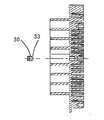
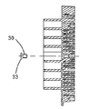
도 7, 8은, 밀봉 부재(30)를 설치한 선회 스크롤 랩 부재(8c)를 구동축의 길이 방향으로부터 본 도면이다. 본 실시예는, 선회 스크롤(8)의 랩부(10)의 중심부(8d)(권취 개시)에 있어서, 밀봉 부재(30)를 구성하기 위해서, 중심부(8d)의 내벽부(8e)를 절결부를 형성한 것이 특징이다.7 and 8 are views of the orbiting
본 실시예에서는, 선회 스크롤(8)의 선회 반경이 작고, 관통 구멍(8a) 및 밀봉 부재(30)[특히 제3 실시예의 테이퍼부(33)]를 구성하기 어려운 경우에 랩 중심부(8d)의 내벽부(8e)를 절결함으로써, 관통 구멍(8a) 및 밀봉 부재(30)의 형성을 용이하게 할 수 있다.In the present embodiment, when the turning radius of the orbiting scroll 8 is small and it is difficult to form the through
지금까지 설명해 온 각 실시예에서는, 스크롤식 유체 기계로서 스크롤식 공기압축기에 적용했을 경우를 예로 들어 설명했지만, 본 발명은 이에 한하지 않고, 냉매를 압축하는 냉매 압축기, 진공 펌프 등 그 밖의 스크롤식 유체 기계에 적용해도 된다. 또한, 스크롤식 유체 기계를 구비한 탱크 일체형 패키지 압축기나 질소 가스 발생 장치라고 하는 시스템에 적용해도 된다.In the embodiments described so far, the scroll type fluid machine is applied to the scroll type air compressor. However, the present invention is not limited to this, and a refrigerant compressor for compressing the refrigerant, It may be applied to a fluid machine. Further, the present invention may be applied to a tank-integrated type compressor having a scroll fluid machine or a system called a nitrogen gas generator.
지금까지 설명해 온 실시예는, 모두 본 발명을 실시하는 데 있어서의 구체화된 일례를 나타낸 것에 지나지 않고, 이들에 의해 본 발명의 기술적 범위가 한정적으로 해석되지 않는다. 즉, 본 발명은 그 기술 사상, 또는 그 주요한 특징으로부터 일탈하는 일 없이, 여러가지 형으로 실시할 수 있다. 또한, 제1 실시예 내지 제5 실시예을 조합함으로써 본 발명을 실시해도 된다.The embodiments described so far are merely illustrative of specific embodiments in the practice of the present invention, and the technical scope of the present invention is not limitedly interpreted by these embodiments. That is, the present invention can be carried out in various forms without departing from the technical idea or the main features thereof. Further, the present invention may be implemented by combining the first to fifth embodiments.
1 : 케이싱
1a : 플랜지
1b : 하우징
2 : 고정 스크롤
3, 9 : 경판
4, 10 : 랩부
5 : 외주 벽부
6, 11 : 냉각 핀
7, 13 : 팁 시일
8 : 선회 스크롤
8a : 관통 구멍
8c : 선회 스크롤 랩 부재
8d : 랩 중심부
8e : 절결부
12 : 배면 플레이트
12a : 관통 구멍
14 : 보스
14a : 선회 베어링
14b : 베어링 하우징
15 : 구동축
16 : 냉각 팬
17 : 팬 케이싱
18 : 보조 크랭크
18a : 보조 크랭크 베어링
18b : 베어링 하우징
19 : 압축실
20 : 흡입구
21 : 흡입 필터
22 : 토출구
23 : 고정 스크롤 경사부
24 : 플랜지
25 : 페이스 시일 홈
26 : 페이스 시일
27 : 오목 홈부
28 : 고정 스크롤 볼록부
29 : 위치 정렬 핀
30 : 밀봉 부재
31 : 볼트
32 : 나사 홈(또는 돌기)
33 : 테이퍼부
34 : 위치 결정 구멍
35 : 핀
36 : 주베어링
36a : 하우징
37 : 위치 결정 구멍1: casing
1a: Flange
1b: housing
2: Fixed scroll
3, 9: Hardboard
4, 10:
5:
6, 11: cooling pin
7, 13: tip seal
8: Turning scroll
8a: Through hole
8c: orbiting scroll wrap member
8d: Wrap center
8e:
12: back plate
12a: Through hole
14: Boss
14a: Swing bearing
14b: bearing housing
15:
16: Cooling fan
17: Fan casing
18: Secondary crank
18a: Secondary crank bearing
18b: bearing housing
19: compression chamber
20: inlet
21: Suction filter
22: Outlet
23: Fixed scroll ramp
24: Flange
25: face seal home
26: Face seal
27: concave groove
28: fixed scroll convex portion
29: Position alignment pin
30: sealing member
31: Bolt
32: screw groove (or projection)
33: taper portion
34: Positioning hole
35: pin
36: Main bearing
36a: housing
37: Positioning hole
Claims (18)
상기 고정 스크롤에 대향해서 설치되고, 상기 고정 스크롤과의 사이에 복수의 압축실을 형성하여 선회 운동하는 선회 스크롤과,
상기 선회 스크롤을 구동하는 구동축과,
상기 구동축과 상기 선회 스크롤 사이에 설치되는 배면 플레이트를 구비하고,
상기 선회 스크롤과 상기 배면 플레이트에 위치 정렬 구멍을 형성하고, 상기 위치 정렬 구멍에 위치 정렬을 행하는 위치 정렬 핀을 설치하여, 상기 압축실을 시일하는 시일 부재를 설치하는 것을 특징으로 하는, 스크롤식 유체 기계.Fixed scroll,
A orbiting scroll installed opposite to the fixed scroll and forming a plurality of compression chambers between the orbiting scroll and the fixed scroll,
A drive shaft for driving the orbiting scroll,
And a rear plate provided between the drive shaft and the orbiting scroll,
Characterized in that a sealing member for sealing the compression chamber is provided by providing a positioning hole in the orbiting scroll and the back plate and for positioning an alignment hole in the positioning hole, machine.
상기 고정 스크롤에 대향하여 설치되고, 상기 고정 스크롤과의 사이에 복수의 압축실을 형성하여 선회 운동하는 선회 스크롤과,
상기 선회 스크롤을 구동하는 구동축과,
상기 구동축과 상기 선회 스크롤 사이에 설치되는 배면 플레이트를 구비하고,
상기 선회 스크롤과 상기 배면 플레이트에 위치 정렬 구멍을 형성하고, 상기 위치 정렬 구멍에 나사 홈 또는 돌기가 설치되어 있지 않은 위치 정렬 핀과 나사 홈 또는 돌기가 설치된 시일 부재를 설치하는 것을 특징으로 하는, 스크롤식 유체 기계.Fixed scroll,
A orbiting scroll installed opposite to the fixed scroll and forming a plurality of compression chambers between the orbiting scroll and the fixed scroll,
A drive shaft for driving the orbiting scroll,
And a rear plate provided between the drive shaft and the orbiting scroll,
Characterized in that a position alignment hole is formed in the orbiting scroll and the back plate and a seal member provided with a positioning pin and a screw groove or projection not provided with a screw groove or a projection in the positioning hole is provided. Expression fluid machinery.
Applications Claiming Priority (2)
| Application Number | Priority Date | Filing Date | Title |
|---|---|---|---|
| JPJP-P-2012-239770 | 2012-10-31 | ||
| JP2012239770A JP5998012B2 (en) | 2012-10-31 | 2012-10-31 | Scroll type fluid machine |
Publications (1)
| Publication Number | Publication Date |
|---|---|
| KR20140055951A true KR20140055951A (en) | 2014-05-09 |
Family
ID=48900738
Family Applications (1)
| Application Number | Title | Priority Date | Filing Date |
|---|---|---|---|
| KR20130091001A KR20140055951A (en) | 2012-10-31 | 2013-07-31 | Scroll type fluid machine |
Country Status (5)
| Country | Link |
|---|---|
| US (1) | US9133846B2 (en) |
| EP (1) | EP2728113A3 (en) |
| JP (1) | JP5998012B2 (en) |
| KR (1) | KR20140055951A (en) |
| CN (1) | CN103790825A (en) |
Families Citing this family (8)
| Publication number | Priority date | Publication date | Assignee | Title |
|---|---|---|---|---|
| CN104061160B (en) * | 2014-06-24 | 2016-01-20 | 广东广顺新能源动力科技有限公司 | A kind of oil-free vortex formula compressor assembly |
| WO2016038694A1 (en) * | 2014-09-10 | 2016-03-17 | 株式会社日立産機システム | Scroll fluid machine |
| CN106122011B (en) * | 2016-04-25 | 2018-09-14 | 徐道敏 | A kind of screw compressor |
| US11085444B2 (en) * | 2016-07-07 | 2021-08-10 | Hitachi Industrial Equipment Systems Co., Ltd. | Scroll-type fluid machine |
| JP1574166S (en) * | 2016-08-31 | 2020-04-06 | ||
| JP1574165S (en) * | 2016-08-31 | 2020-04-06 | ||
| WO2019039575A1 (en) * | 2017-08-25 | 2019-02-28 | 三菱重工業株式会社 | Twin rotary scroll type compressor |
| US10767688B2 (en) * | 2018-03-27 | 2020-09-08 | Roller Bearing Company Of America, Inc. | Bearing system for an articulating motor device |
Family Cites Families (16)
| Publication number | Priority date | Publication date | Assignee | Title |
|---|---|---|---|---|
| JPH02124288U (en) * | 1989-03-22 | 1990-10-12 | ||
| US5106279A (en) | 1991-02-04 | 1992-04-21 | Tecumseh Products Company | Orbiting scroll member assembly |
| JPH06341384A (en) * | 1993-06-02 | 1994-12-13 | Kobe Steel Ltd | Oil-free scroll compressor |
| JP3653128B2 (en) * | 1995-09-01 | 2005-05-25 | 株式会社日立製作所 | Scroll type fluid machine |
| JP3424881B2 (en) * | 1995-09-01 | 2003-07-07 | トキコ株式会社 | Scroll type fluid machine |
| JP2002213376A (en) * | 2001-01-19 | 2002-07-31 | Anest Iwata Corp | Scroll fluid machine |
| JP4824231B2 (en) * | 2001-09-28 | 2011-11-30 | 株式会社日立産機システム | Assembling method of scroll type fluid machine |
| JP4510495B2 (en) * | 2004-03-30 | 2010-07-21 | アネスト岩田株式会社 | Scroll fluid machinery |
| JP2005337189A (en) * | 2004-05-31 | 2005-12-08 | Anest Iwata Corp | Method for manufacturing revolving scroll of scroll fluid machine |
| JP4303182B2 (en) * | 2004-09-30 | 2009-07-29 | 株式会社日立製作所 | Scroll type fluid machine |
| JP4629546B2 (en) * | 2005-09-30 | 2011-02-09 | アネスト岩田株式会社 | Scroll fluid machinery |
| JP4920244B2 (en) * | 2005-11-08 | 2012-04-18 | アネスト岩田株式会社 | Scroll fluid machinery |
| JP2007162602A (en) | 2005-12-15 | 2007-06-28 | Mitsubishi Electric Corp | Scroll compressor |
| JP5048303B2 (en) * | 2006-10-31 | 2012-10-17 | 株式会社日立産機システム | Scroll type fluid machine |
| US7901194B2 (en) * | 2008-04-09 | 2011-03-08 | Hamilton Sundstrand Corporation | Shaft coupling for scroll compressor |
| JP2011038492A (en) | 2009-08-18 | 2011-02-24 | Honda Motor Co Ltd | Scroll compressor |
-
2012
- 2012-10-31 JP JP2012239770A patent/JP5998012B2/en active Active
-
2013
- 2013-07-29 EP EP13003766.6A patent/EP2728113A3/en not_active Withdrawn
- 2013-07-30 US US13/953,910 patent/US9133846B2/en active Active
- 2013-07-31 KR KR20130091001A patent/KR20140055951A/en active Search and Examination
- 2013-08-01 CN CN201310331700.4A patent/CN103790825A/en active Pending
Also Published As
| Publication number | Publication date |
|---|---|
| US20140119970A1 (en) | 2014-05-01 |
| CN103790825A (en) | 2014-05-14 |
| JP5998012B2 (en) | 2016-09-28 |
| EP2728113A2 (en) | 2014-05-07 |
| JP2014088839A (en) | 2014-05-15 |
| US9133846B2 (en) | 2015-09-15 |
| EP2728113A3 (en) | 2018-03-07 |
Similar Documents
| Publication | Publication Date | Title |
|---|---|---|
| KR20140055951A (en) | Scroll type fluid machine | |
| JP5577297B2 (en) | Scroll type fluid machine | |
| JP2008215108A (en) | Seal device and scroll type fluid machine | |
| KR20070119477A (en) | Fluid apparatus and scroll compressor | |
| EP2410181B1 (en) | Vane compressor | |
| US20090116988A1 (en) | Scroll-Type Fluid Machine | |
| JP5088493B2 (en) | Seal structure and turbocharger | |
| JP7439690B2 (en) | Compressor, compressor manufacturing method | |
| US8714950B2 (en) | Scroll compressor having tip seals of different lengths having different thickness or widths | |
| US6663367B2 (en) | Shaft seal structure of vacuum pumps | |
| JP6205478B2 (en) | Scroll type fluid machine | |
| JP2006283673A (en) | Scroll type fluid machine | |
| CN113544360B (en) | Oldham coupling for co-rotating scroll compressor | |
| JP5865960B2 (en) | Compressor | |
| JP2018071359A (en) | Scroll fluid machine | |
| JP6302411B2 (en) | Liquid ring vacuum pump | |
| JP2010014051A (en) | Centrifugal compressor | |
| JP2010150958A (en) | Vane pump | |
| JP2020029819A (en) | Root blower | |
| JP7143450B2 (en) | Double-rotating scroll compressor | |
| WO2023042328A1 (en) | Scroll type fluid machine | |
| JP6596787B2 (en) | Scroll compressor | |
| JP6609849B2 (en) | Scroll compressor | |
| KR20160089779A (en) | Scroll compressor | |
| JP2023140880A (en) | Root pump |
Legal Events
| Date | Code | Title | Description |
|---|---|---|---|
| A201 | Request for examination | ||
| E902 | Notification of reason for refusal | ||
| AMND | Amendment | ||
| E601 | Decision to refuse application | ||
| AMND | Amendment |