WO2022019009A1 - 電磁継電器 - Google Patents
電磁継電器 Download PDFInfo
- Publication number
- WO2022019009A1 WO2022019009A1 PCT/JP2021/022787 JP2021022787W WO2022019009A1 WO 2022019009 A1 WO2022019009 A1 WO 2022019009A1 JP 2021022787 W JP2021022787 W JP 2021022787W WO 2022019009 A1 WO2022019009 A1 WO 2022019009A1
- Authority
- WO
- WIPO (PCT)
- Prior art keywords
- contact
- movable
- electromagnetic relay
- fixed
- movable contact
- Prior art date
- Legal status (The legal status is an assumption and is not a legal conclusion. Google has not performed a legal analysis and makes no representation as to the accuracy of the status listed.)
- Ceased
Links
Images



Classifications
-
- H—ELECTRICITY
- H01—ELECTRIC ELEMENTS
- H01H—ELECTRIC SWITCHES; RELAYS; SELECTORS; EMERGENCY PROTECTIVE DEVICES
- H01H1/00—Contacts
- H01H1/06—Contacts characterised by the shape or structure of the contact-making surface, e.g. grooved
-
- H—ELECTRICITY
- H01—ELECTRIC ELEMENTS
- H01H—ELECTRIC SWITCHES; RELAYS; SELECTORS; EMERGENCY PROTECTIVE DEVICES
- H01H50/00—Details of electromagnetic relays
- H01H50/16—Magnetic circuit arrangements
- H01H50/36—Stationary parts of magnetic circuit, e.g. yoke
- H01H50/38—Part of main magnetic circuit shaped to suppress arcing between the contacts of the relay
-
- H—ELECTRICITY
- H01—ELECTRIC ELEMENTS
- H01H—ELECTRIC SWITCHES; RELAYS; SELECTORS; EMERGENCY PROTECTIVE DEVICES
- H01H50/00—Details of electromagnetic relays
- H01H50/54—Contact arrangements
Definitions
- the present invention relates to an electromagnetic relay.
- the electromagnetic relay disclosed in Patent Document 1 includes a magnet that generates a magnetic field between the contacts.
- the magnet generates a magnetic field perpendicular to the direction in which the contacts face each other.
- An object of the present invention is to quickly extinguish an arc in an electromagnetic relay and prevent the electromagnetic relay from becoming large in size.
- the electromagnetic relay includes a first contact, a second contact, and a magnet.
- the first contact includes a first surface.
- the second contact includes a second surface facing the first surface.
- the magnet generates a magnetic field between the first contact and the second contact.
- the first surface has a diameter larger than the diameter of the second surface.
- the first surface has a curvature smaller than the curvature of the second surface.
- the distance between the first surface and the second surface increases as the distance from the center of the first surface increases. Therefore, the arc is greatly stretched as compared with the case where the first surface is flat. Further, when the arc is greatly stretched, the Lorentz force acting on the arc becomes large. This makes it easier for the bright spots of the arc to move. As a result, the arc is quickly extinguished. Further, since the above effect can be obtained by the shape of the first contact, it is possible to prevent the electromagnetic relay from becoming large in size.
- the first contact may have a diameter larger than the diameter of the second contact. In this case, the distance between the end of the first contact and the end of the second contact becomes large. Therefore, when the arc is greatly stretched, the arc is quickly extinguished.
- the magnet may generate a magnetic field for applying Lorentz force to the arc generated between the first surface and the second surface.
- the distance between the first surface and the second surface may increase from the center of the first surface toward the direction of action of the Lorentz force. In this case, the arc moves in the direction of action of the Lorentz force, so that the arc is greatly extended. As a result, the arc is quickly extinguished.
- the electromagnetic relay may further include a first mounting surface and a second mounting surface.
- the first contact may be mounted on the first mounting surface.
- a second contact may be mounted on the second mounting surface.
- the height from the second mounting surface to the second surface may be larger than the height from the first mounting surface to the first surface. In this case, by increasing the volume of the second contact, it is possible to suppress the temperature rise of the second contact during energization.
- the second contact may further include a second side surface located between the second surface and the second mounting surface.
- the angle between the second side surface and the second mounting surface may be an obtuse angle. In this case, the arc can easily move from the second contact to the second mounting surface. As a result, the arc is quickly extinguished.
- the second surface may include a central portion and a peripheral portion.
- the peripheral portion may be located around the central portion.
- the height from the second mounting surface to the peripheral portion may be smaller than the height from the second mounting surface to the central portion.
- FIG. 3 is a sectional view taken along line III-III in FIG. It is a side view of a 1st movable contact and a 1st fixed contact. It is a top view of the first movable contact. It is sectional drawing of the 1st movable contact. It is a side view of the 1st fixed contact and 1st movable contact which concerns on 1st modification. It is a side view of the 1st fixed contact and 1st movable contact which concerns on 2nd modification. It is sectional drawing of the electromagnetic relay which concerns on a modification.
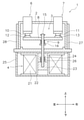
- FIG. 1 is a front sectional view of the electromagnetic relay 1.
- the electromagnetic relay 1 includes a housing 2, a contact device 3, and a drive device 4.
- FIG. 1 When referring to the drawings, the upper side in FIG. 1 will be described as “upper”, the lower side as “lower side”, the left side as “left”, and the right side as “right” in order to make the explanation easier to understand. Further, the front side of the paper in FIG. 1 will be described as “front” and the back side will be described as “rear”. However, these directions are defined for convenience of explanation, and do not limit the arrangement direction of the electromagnetic relay 1.
- the housing 2 is made of an insulating material such as resin. However, the housing 2 may be made of another material such as ceramic.
- the contact device 3 is housed in the housing 2.
- the contact device 3 includes a first fixed terminal 6, a second fixed terminal 7, a movable contact piece 8, and a movable mechanism 9.
- the first fixed terminal 6 and the second fixed terminal 7 extend in the moving direction of the movable contact piece 8.
- the first fixed terminal 6 and the second fixed terminal 7 are arranged so as to be spaced apart from each other in the left-right direction.
- a part of the first fixed terminal 6 and a part of the second fixed terminal 7 project to the outside of the housing 2.
- the first fixed contact 10 is connected to the first fixed terminal 6.
- a second fixed contact 11 is connected to the second fixed terminal 7.
- the first fixed contact 10 and the second fixed contact 11 are arranged in the housing 2.
- the movable contact piece 8 extends in the left-right direction.
- the movable contact piece 8 is arranged in the housing 2.
- the first movable contact 12 and the second movable contact 13 are connected to the movable contact piece 8.
- the first movable contact 12 faces the first fixed contact 10.
- the second movable contact 13 faces the second fixed contact 11.
- the first movable contact 12 is arranged at a distance from the second movable contact 13 in the left-right direction.
- the movable contact piece 8 can move in the contact direction and the release direction.
- the contact direction is the direction in which the movable contacts 12 and 13 approach the fixed contacts 10 and 11.
- the opening direction is the direction in which the movable contacts 12 and 13 are separated from the fixed contacts 10 and 11.
- the movable contact piece 8 can move in the vertical direction.
- the movable mechanism 9 supports the movable contact piece 8.
- the movable mechanism 9 is provided so as to be movable between a closed position and an open position. When the movable mechanism 9 is in the closed position, the fixed contacts 10 and 11 and the movable contacts 12 and 13 come into contact with each other. When the movable mechanism 9 is in the open position, the fixed contacts 10 and 11 and the movable contacts 12 and 13 are separated from each other.
- the movable mechanism 9 includes a drive shaft 15 and a contact spring 16.
- the drive shaft 15 is connected to the movable contact piece 8.
- the drive shaft 15 extends in the vertical direction and penetrates the movable contact piece 8 in the vertical direction.
- the drive shaft 15 is provided so as to be movable in the vertical direction.
- the contact spring 16 urges the movable contact piece 8 in the contact direction.
- the drive device 4 includes a coil 21, a spool 22, a movable iron core 23, a fixed iron core 24, a yoke 25, and a return spring 26.
- the drive device 4 moves the movable contact piece 8 in the contact direction and the opening direction via the movable mechanism 9 by an electromagnetic force.
- the coil 21 is wound around the spool 22.
- the movable core 23 and the fixed core 24 are arranged in the spool 22.
- the movable iron core 23 is connected to the drive shaft 15.
- the movable iron core 23 is movable in the vertical direction.
- the fixed iron core 24 is arranged so as to face the movable iron core 23.
- the return spring 26 urges the movable iron core 23 in the opening direction.
- the electromagnetic relay 1 shown in FIG. 1 is in the open state.
- the movable contacts 12 and 13 are separated from the fixed contacts 10 and 11.
- the movable iron core 23 is attracted to the fixed core 24 by the magnetic force generated by the magnetic field generated from the coil 21.
- the movable iron core 23 and the drive shaft 15 move in the contact direction against the urging force of the return spring 26.
- the movable contact piece 8 and the movable contacts 12 and 13 move in the contact direction, and the movable contacts 12 and 13 come into contact with the fixed contacts 10 and 11.
- the electromagnetic relay 1 is closed as shown in FIG. After the movable contacts 12 and 13 come into contact with the fixed contacts 10 and 11, the drive shaft 15 further moves in the contact direction, so that the contact spring 16 is compressed.
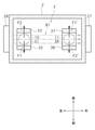
- FIG. 3 is a sectional view taken along line III-III in FIG.
- the electromagnetic relay 1 includes magnets 27 and 28.
- the magnets 27 and 28 are permanent magnets. However, one of the magnets 27 and 28 may be a yoke.
- the magnets 27 and 28 are arranged so that the bright spots of the arcs generated at the contacts 10-13 are moved in a predetermined direction by magnetic force.
- the magnets 27 and 28 generate a magnetic field B1 in the housing 2.
- the arrow of the alternate long and short dash line indicates the direction of the magnetic field B1.
- the magnets 27 and 28 generate a magnetic field B1 between the first movable contact 12 and the first fixed contact 10.
- the magnetic field B1 has a magnetic flux in a direction perpendicular to the direction in which the first movable contact 12 and the first fixed contact 10 face each other.
- the magnets 27 and 28 generate a magnetic field B1 between the second movable contact 13 and the second fixed contact 11.
- the magnetic field B1 has a magnetic flux in a direction perpendicular to the direction in which the second movable contact 13 and the second fixed contact 11 face each other.
- the solid arrows F1 and F1' indicate the direction of the Lorentz force (hereinafter referred to as "first Lorentz force") when the current flows in the positive direction.
- the positive direction means a current flow from the first fixed terminal 6 to the second fixed terminal 7 via the movable contact piece 8.
- the bright spot of the arc generated between the first movable contact 12 and the first fixed contact 10 moves in the direction of the first Lorentz force F1.
- the bright spot of the arc generated between the second movable contact 13 and the second fixed contact 11 moves in the direction of the first Lorentz force F1'.
- the broken line arrows F2 and F2' indicate the direction of the Lorentz force (hereinafter referred to as "second Lorentz force") when the current flows in the opposite direction.
- the reverse direction means a current flow from the second fixed terminal 7 to the first fixed terminal 6 via the movable contact piece 8.
- the bright spot of the arc generated between the first movable contact 12 and the first fixed contact 10 moves in the direction of the second Lorentz force F2.
- the bright spot of the arc generated between the second movable contact 13 and the second fixed contact 11 moves in the direction of the second Lorentz force F2'.
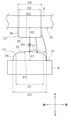
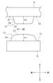
- FIG. 4 is a side view of the first movable contact 12 and the first fixed contact 10.
- FIG. 5 is a top view of the first movable contact 12.
- the first movable contact 12 has a diameter larger than the diameter of the first fixed contact 10.
- the movable contact piece 8 includes a first mounting surface 31.
- the first movable contact 12 is attached to the first mounting surface 31.
- the first fixed terminal 6 includes a second mounting surface 32.
- the first fixed contact 10 is attached to the second mounting surface 32.
- the first movable contact 12 includes a first surface 33 and a first side surface 34.
- the first surface 33 is arranged at the center of the first movable contact 12.
- the first side surface 34 is located between the first surface 33 and the first mounting surface 31.
- the first side surface 34 is arranged around the first surface 33.
- the first side surface 34 is located radially outward of the first surface 33.
- the first side surface 34 is inclined with respect to the vertical direction and the horizontal direction.
- the first fixed contact 10 includes a second surface 35 and a second side surface 36.
- the second surface 35 is arranged at the center of the first fixed contact 10.
- the second side surface 36 is located between the second surface 35 and the second mounting surface 32.
- the second side surface 36 is arranged around the second surface 35.
- the second side surface 36 is located radially outward of the second surface 35.
- the second side surface 36 extends in the vertical direction.
- the first surface 33 has a diameter D1 larger than the diameter D2 of the second surface 35.
- the first surface 33 has a curvature R1 smaller than the curvature R2 of the second surface 35.
- the second surface 35 may be flat.
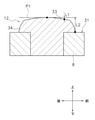
- FIG. 6 is a cross-sectional view of the first movable contact 12. As shown in FIG. 6, the distance L1 between the plane P1 and the first surface 33 increases in the radial direction of the first movable contact 12.
- the plane P1 is a horizontal virtual plane passing through the vertices of the first surface 33.
- the distance L2 between the plane P1 and the first side surface 34 increases in the radial direction of the first movable contact 12.
- the second surface 35 and the second side surface 36 face the first surface 33.
- the second surface 35 and the second side surface 36 are located directly above the first surface 33. That is, in top view, the second surface 35 and the second side surface 36 overlap with the first surface 33.
- the diameter D4 of the second side surface 36 is smaller than the diameter D3 of the first side surface 34.
- the diameter D4 of the second side surface 36 is smaller than the diameter D1 of the first surface 33.
- the second side surface 36 may be inclined with respect to the vertical direction. In that case, the diameter D4 of the second side surface 36 described above may be the maximum value of the diameter of the second side surface 36.
- the diameter D3 of the first side surface 34 means the maximum value of the diameter of the first side surface 34.
- the height H2 from the second mounting surface 32 to the second surface 35 is larger than the height H1 from the first mounting surface 31 to the first surface 33.
- the height H2 from the second mounting surface 32 to the second surface 35 means the maximum value of the height from the second mounting surface 32 to the second surface 35.
- the height H1 from the first mounting surface 31 to the first surface 33 means the maximum value of the height from the first mounting surface 31 to the first surface 33.
- the magnets 27 and 28 generate a magnetic field B1 between the first movable contact 12 and the first fixed contact 10.
- the first Lorentz force F1 acts on the arc generated between the first movable contact 12 and the first fixed contact 10.
- the broken line indicates an arc.
- the distance between the first surface 33 and the second surface 35 increases from the center of the first surface 33 toward the acting direction of the first Lorentz force F1.
- the distance between the first surface 33 and the second surface 35 increases as the distance from the center of the first surface 33 toward the first Lorentz force F1 increases. Therefore, the arc is greatly extended as compared with the case where the first surface 33 is flat. Further, when the arc is greatly stretched, the Lorentz force acting on the arc becomes large. This makes it easier for the bright spots of the arc to move. As a result, the arc is quickly extinguished. Further, since the above effect can be obtained by the shape of the first movable contact 12, it is possible to prevent the electromagnetic relay 1 from becoming large in size.
- the temperature of the first fixed contact 10 tends to rise due to energization.
- the height H2 of the first fixed contact 10 is larger than the height H1 of the first movable contact 12. As a result, the volume of the first fixed contact 10 is increased, so that the temperature rise of the first fixed contact 10 at the time of energization is suppressed.
- the second fixed contact 11 has the same shape as the first fixed contact 10.
- the second movable contact 13 has the same shape as the first movable contact 12.
- the second fixed contact 11 may have the same shape as the first movable contact 12.
- the second movable contact 13 may have the same shape as the first fixed contact 10.
- the shape of the movable contact piece 8 may be changed.
- the first movable contact 12 and the second movable contact 13 may be integrated with the movable contact piece 8.
- the first fixed contact 10 may be integrated with the first fixed terminal 6.
- the second fixed contact 11 may be integrated with the second fixed terminal 7.
- the number of movable contacts is not limited to two, and may be more than two.
- the number of fixed contacts is not limited to two, and may be more than two.
- the configuration of the movable mechanism 9 is not limited to that of the above embodiment, and may be changed.
- the configuration of the drive device 4 is not limited to that of the above embodiment, and may be changed.
- the arrangement of the magnets 27 and 28 or the arrangement of the magnetic field B1 by the magnets 27 and 28 may be changed.
- the shapes of the first fixed contact 10 and the first movable contact 12 are not limited to those of the above embodiment, and may be changed.
- the shapes of the second fixed contact 11 and the second movable contact 13 are not limited to those of the above embodiment, and may be changed.
- the fixed contacts 10 and 11 may be formed of a plurality of materials or may be formed of a single material.
- the movable contacts 12 and 13 may be formed of a plurality of materials or may be formed of a single material.
- FIG. 7 is a side view of the first fixed contact 10 and the first movable contact 12 according to the first modification.
- the angle ⁇ between the second side surface 36 of the first fixed contact 10 and the second mounting surface 32 may be an obtuse angle.
- the arc can easily move from the first fixed contact 10 to the second mounting surface 32. As a result, the arc is quickly extinguished.
- FIG. 8 is a side view of the first fixed contact 10 and the first movable contact 12 according to the second modification.
- the second surface 35 may include a central portion 37, a peripheral portion 38, and a step portion 39.
- the central portion 37 is located at the center of the first fixed contact 10.
- the peripheral portion 38 is located around the central portion 37.
- the step portion 39 is located between the central portion 37 and the peripheral portion 38.
- the step portion 39 projects from the peripheral portion 38 toward the central portion 37.
- the height H4 from the second mounting surface 32 to the peripheral portion 38 is smaller than the height H3 from the second mounting surface 32 to the central portion 37. In this case, the arc can easily move from the first fixed contact 10 to the second mounting surface 32. As a result, the arc is quickly extinguished.
- the first movable contact 12 is an example of the first contact
- the first fixed contact 10 is an example of the second contact
- the first movable contact 12 may be an example of the second contact
- the first fixed contact 10 may be an example of the first contact. That is, the shapes of the first movable contact 12 and the first fixed contact 10 may be opposite to those of the above embodiment.
- the shapes of the first movable contact 12 and the first fixed contact 10 may be reversed.
- the first movable contact 12 may have the same shape as the first fixed contact 10.
- the electromagnetic relay 1 is a so-called plunger type electromagnetic relay.
- the electromagnetic relay may be of another type.
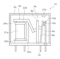
- FIG. 9 is a cross-sectional view of an electromagnetic relay 1a according to a modified example.
- the electromagnetic relay 1a according to the modified example is a so-called hinge type electromagnetic relay.
- the hinge type electromagnetic relay 1a includes a housing 2a, a contact device 3a, and a drive device 4a.
- the drive device 4a includes a coil 21a, a spool 22a, a movable iron piece 23a, an iron core 24a, and a yoke 25a.
- the coil 21a is wound around the spool 22a.
- the iron core 24a is arranged in the spool 22a.
- the movable iron piece 23a is attracted to the iron core 24a by the magnetic field generated by the coil 21a.
- a return spring (not shown) is attached to the movable iron piece 23a.
- the contact device 3a includes a first terminal 6a, a second terminal 7a, a movable contact piece 8a, a fixed contact 10a, a movable contact 12a, and a card 9a.
- the first terminal 6a and the second terminal 7a project to the outside of the housing 2a.
- the fixed contact 10a is attached to the first terminal 6a.
- the movable contact piece 8a is connected to the second terminal 7a.
- the movable contact 12a is attached to the movable contact piece 8a.
- the movable contact 12a faces the fixed contact 10a.
- the card 9a is arranged between the movable iron piece 23a and the movable contact piece 8a.
- the movable iron piece 23a When the coil 21a is energized, the movable iron piece 23a is attracted to the iron core 24a to press the card 9a. As a result, the card 9a presses the movable contact piece 8a. As a result, the movable contact 12a comes into contact with the fixed contact 10a. When the energization of the coil 21a is released, the movable iron piece 23a returns to its original position due to the elastic force of the return spring. As a result, the pressure on the movable contact piece 8a by the card 9a is released, and the movable contact piece 8a returns to its original position due to the elastic force of the movable contact piece 8a. As a result, the movable contact 12a is separated from the fixed contact 10a.
- the electromagnetic relay 1a includes a magnet 27a.
- the magnet 27a generates a magnetic field between the movable contact 12a and the fixed contact 10a.
- the Lorentz force acts on the arc generated between the movable contact 12a and the fixed contact 10a.
- the movable contact 12a may have the same shape as the first fixed contact 10a of the above-described embodiment.
- the fixed contact 10a may have the same shape as the first movable contact 12a of the above-described embodiment.
- the movable contact 12a may have the same shape as the first movable contact 12a of the above-described embodiment.
- the fixed contact 10a may have the same shape as the first fixed contact 10a of the above-described embodiment.
Landscapes
- Physics & Mathematics (AREA)
- Electromagnetism (AREA)
- Contacts (AREA)
- Arc-Extinguishing Devices That Are Switches (AREA)
Abstract
電磁継電器は、第1接点と、第2接点と、磁石とを備える。第1接点は、第1表面を含む。第2接点は、第1表面と向かい合う第2表面を含む。磁石は、第1接点と第2接点との間に磁界を発生させる。第1表面は、第2表面の直径よりも大きな直径を有する。第1表面は、第2表面の曲率よりも小さな曲率を有する。
Description
本発明は、電磁継電器に関する。
電磁継電器では、接点間にアークが発生することがある。その場合、アークにより電磁継電器の機械寿命が低下してしまう。そのため、例えば特許文献1に開示されている電磁継電器は、接点間に磁界を発生させる磁石を備えている。磁石は、接点が互いに向かい合う方向に対して垂直に磁界を発生させる。
上記の電磁継電器では、磁界によりアークにローレンツ力が作用することで、アークが、アーク消去空間へ向けて引き延ばされる。それにより、アークが消弧される。アークを迅速に消弧するためには、アーク消去空間は広いことが好ましい。しかし、アーク消去空間を拡大させることは、電磁継電器の大型化の要因となりうる。本発明の目的は、電磁継電器においてアークを迅速に消弧すると共に、電磁継電器の大型化を防止することにある。
本発明の一態様に係る電磁継電器は、第1接点と、第2接点と、磁石とを備える。第1接点は、第1表面を含む。第2接点は、第1表面と向かい合う第2表面を含む。磁石は、第1接点と第2接点との間に磁界を発生させる。第1表面は、第2表面の直径よりも大きな直径を有する。第1表面は、第2表面の曲率よりも小さな曲率を有する。
本態様に係る電磁継電器では、第1表面の中心から離れるほど、第1表面と第2表面との間の距離が大きくなる。そのため、第1表面が平坦である場合と比べて、アークが大きく引き伸ばされる。また、アークが大きく引き伸ばされることで、アークに作用するローレンツ力が大きくなる。それにより、アークの輝点が移動しやすくなる。それにより、アークが迅速に消弧される。また、第1接点の形状により上記の効果が得られるため、電磁継電器の大型化を防止することができる。
第1接点は、第2接点の直径よりも大きな直径を有してもよい。この場合、第1接点の端部と第2接点の端部との間の距離が大きくなる。従って、アークが大きく引き伸ばされることで、アークが迅速に消弧される。
磁石は、第1表面と第2表面との間に発生したアークにローレンツ力を作用させるための磁界を発生させてもよい。第1表面と第2表面との間の距離は、第1表面の中心からローレンツ力の作用方向に向かって大きくなってもよい。この場合、アークがローレンツ力の作用方向に移動することで、アークが大きく引き伸ばされる。それにより、アークが迅速に消弧される。
電磁継電器は、第1取付面と第2取付面とをさらに備えてもよい。第1取付面には、第1接点が取り付けられてもよい。第2取付面には、第2接点が取り付けられてもよい。第2取付面から第2表面までの高さは、第1取付面から第1表面までの高さよりも大きくてもよい。この場合、第2接点の体積が大きくなることで、通電時の第2接点の温度上昇を抑えることができる。
第2接点は、第2表面と第2取付面との間に位置する第2側面をさらに含んでもよい。第2側面と第2取付面との間に角度は、鈍角であってもよい。この場合、アークが、第2接点から第2取付面へ移動し易くなる。それにより、アークが迅速に消弧される。
第2表面は、中心部と周辺部とを含んでもよい。周辺部は、中心部の周囲に位置してもよい。第2取付面から周辺部までの高さは、第2取付面から中心部までの高さよりも小さくてもよい。この場合、アークが、第2接点から第2取付面へ移動し易くなる。それにより、アークが迅速に消弧される。
本発明によれば、電磁継電器においてアークを迅速に消弧すると共に、電磁継電器の大型化を防止することができる。
以下、本発明の一態様に係る電磁継電器1の実施形態について、図面を参照して説明する。図1は電磁継電器1の正面断面図である。図1に示すように、電磁継電器1は、ハウジング2と、接点装置3と、駆動装置4とを備えている。
なお、図面を参照するときにおいて、説明を分かり易くするために図1における上側を「上」、下側を「下」、左側を「左」、右側を「右」として説明する。また、図1における紙面の手前側を「前」、奥側を「後」として説明する。ただし、これらの方向は、説明の便宜上、定義されるものであって、電磁継電器1の配置方向を限定するものではない。
ハウジング2は、樹脂などの絶縁性を有する材料で形成されている。ただし、ハウジング2は、セラミックなどの他の材料製であってもよい。ハウジング2内には、接点装置3が収容されている。
接点装置3は、第1固定端子6と、第2固定端子7と、可動接触片8と、可動機構9とを含む。第1固定端子6と第2固定端子7とは、可動接触片8の移動方向に延びている。第1固定端子6と第2固定端子7とは、左右方向に互いに間隔を隔てて配置されている。第1固定端子6の一部と、第2固定端子7の一部とは、ハウジング2の外部に突出している。第1固定端子6には、第1固定接点10が接続されている。第2固定端子7には、第2固定接点11が接続されている。第1固定接点10と第2固定接点11とは、ハウジング2内に配置されている。
可動接触片8は、左右方向に延びている。可動接触片8は、ハウジング2内に配置されている。可動接触片8には、第1可動接点12と第2可動接点13とが接続されている。第1可動接点12は、第1固定接点10に向かい合っている。第2可動接点13は、第2固定接点11に向かい合っている。第1可動接点12は、第2可動接点13と左右方向に間隔を隔てて配置されている。
可動接触片8は、接触方向と開離方向とに移動可能である。接触方向は、可動接点12,13が、固定接点10,11に近づく方向である。開離方向は、可動接点12,13が、固定接点10,11から離れる方向である。本実施形態では、可動接触片8は、上下方向に移動可能である。
可動機構9は、可動接触片8を支持する。可動機構9は、閉位置と開位置とに移動可能に設けられる。可動機構9が閉位置では、固定接点10,11と可動接点12,13とが互いに接触する。可動機構9が開位置では、固定接点10,11と可動接点12,13とが互いに開離する。可動機構9は、駆動軸15と接点バネ16とを含む。駆動軸15は、可動接触片8に連結される。駆動軸15は、上下方向に延びており、可動接触片8を上下方向に貫通している。駆動軸15は、上下方向に移動可能に設けられる。接点バネ16は、可動接触片8を接触方向に付勢する。
駆動装置4は、コイル21と、スプール22と、可動鉄心23と、固定鉄心24と、ヨーク25と、復帰バネ26とを含む。駆動装置4は、電磁力によって、可動機構9を介して可動接触片8を接触方向と開離方向とに移動させる。コイル21は、スプール22に巻回されている。可動鉄心23と、固定鉄心24とは、スプール22内に配置されている。可動鉄心23は、駆動軸15に接続されている。可動鉄心23は、上下方向に移動可能である。固定鉄心24は、可動鉄心23と向かい合って配置されている。復帰バネ26は、可動鉄心23を開離方向に付勢している。
図1に示す電磁継電器1は、開状態である。開状態では、可動接点12,13は、固定接点10,11から開離している。コイル21が通電されると、コイル21から発生する磁界による磁力によって、可動鉄心23が固定鉄心24に吸引される。それにより、可動鉄心23と駆動軸15とが、復帰バネ26の付勢力に抗して、接触方向に移動する。それにより、図2に示すように、可動接触片8と可動接点12,13とが接触方向に移動し、可動接点12,13が固定接点10,11に接触する。それにより、電磁継電器1は、図2に示すように閉状態となる。なお、可動接点12,13が固定接点10,11に接触した後、駆動軸15がさらに接触方向へ移動することによって、接点バネ16が圧縮される。
コイル21への通電がオフにされると、可動鉄心23と駆動軸15とが、復帰バネ26の付勢力によって、開離方向へ移動する。それにより、可動接触片8と可動接点12,13とが開離方向に移動し、図1に示すように、可動接点12,13が固定接点10,11から開離する。
図3は、図1におけるIII-III断面図である。図3に示すように、電磁継電器1は、磁石27,28を備えている。磁石27,28は、永久磁石である。ただし、磁石27,28の一方は、ヨークであってもよい。磁石27,28は、接点10-13において発生するアークの輝点を、磁力によって所定方向に向かって移動させるように配置される。
図3に示すように、磁石27,28は、ハウジング2内に磁界B1を発生させる。図3において、二点鎖線の矢印は、磁界B1の向きを示している。磁石27,28は、第1可動接点12と第1固定接点10との間に、磁界B1を発生させる。磁界B1は、第1可動接点12と第1固定接点10とが向かい合う方向に対して垂直な方向への磁束を有する。磁石27,28は、第2可動接点13と第2固定接点11との間に、磁界B1を発生させる。磁界B1は、第2可動接点13と第2固定接点11とが向かい合う方向に対して垂直な方向への磁束を有する。それにより、接点10-13に生じるアークにローレンツ力が作用して、アークの輝点が、ローレンツ力の方向に移動する。また、アークが、ローレンツ力の方向に伸長される。
図3において、実線の矢印F1,F1’は、電流が正方向に流れる場合のローレンツ力(以下、「第1ローレンツ力」と呼ぶ)の向きを示している。正方向とは、第1固定端子6から、可動接触片8を経て、第2固定端子7への電流の流れを意味する。電流が正方向に流れる場合、第1可動接点12と第1固定接点10との間に発生したアークの輝点は、第1ローレンツ力F1の方向に移動する。第2可動接点13と第2固定接点11との間に発生したアークの輝点は、第1ローレンツ力F1’の方向に移動する。
図3において、破線の矢印F2,F2’は、電流が逆方向に流れる場合のローレンツ力(以下、「第2ローレンツ力」と呼ぶ)の向きを示している。逆方向とは、第2固定端子7から、可動接触片8を経て、第1固定端子6への電流の流れを意味する。電流が逆方向に流れる場合、第1可動接点12と第1固定接点10との間に発生したアークの輝点は、第2ローレンツ力F2の方向に移動する。第2可動接点13と第2固定接点11との間に発生したアークの輝点は、第2ローレンツ力F2’の方向に移動する。
図4は、第1可動接点12と第1固定接点10との側面図である。図5は、第1可動接点12の上面図である。図4に示すように、第1可動接点12は、第1固定接点10の直径よりも大きな直径を有する。可動接触片8は、第1取付面31を含む。第1可動接点12は、第1取付面31に取り付けられている。第1固定端子6は、第2取付面32を含む。第1固定接点10は、第2取付面32に取り付けられている。
図4および図5に示すように、第1可動接点12は、第1表面33と第1側面34とを含む。第1表面33は、第1可動接点12の中心に配置されている。第1側面34は、第1表面33と第1取付面31との間に位置している。第1側面34は、第1表面33の周囲に配置されている。図5に示すように、第1側面34は、第1表面33の径方向外方に位置している。第1側面34は、上下方向及び水平方向に対して傾斜している。
第1固定接点10は、第2表面35と第2側面36とを含む。第2表面35は、第1固定接点10の中心に配置されている。第2側面36は、第2表面35と第2取付面32との間に位置している。第2側面36は、第2表面35の周囲に配置されている。第2側面36は、第2表面35の径方向外方に位置している。第2側面36は、上下方向に延びている。
第1表面33は、第2表面35の直径D2よりも大きな直径D1を有する。第1表面33は、第2表面35の曲率R2よりも小さな曲率R1を有する。なお、第2表面35は平坦であってもよい。図6は、第1可動接点12の断面図である。図6に示すように、平面P1と第1表面33との間の距離L1は、第1可動接点12の径方向外方に向かって大きくなる。平面P1は、第1表面33の頂点を通る水平な仮想面である。平面P1と第1側面34との間の距離L2は、第1可動接点12の径方向外方に向かって大きくなる。
第2表面35と第2側面36とは、第1表面33と向かい合っている。第2表面35と第2側面36とは、第1表面33の直上に位置している。すなわち、上面視で、第2表面35と第2側面36とは、第1表面33と重なる。第2側面36の直径D4は、第1側面34の直径D3よりも小さい。第2側面36の直径D4は、第1表面33の直径D1よりも小さい。第2側面36は、上下方向に対して傾斜していてもよい。その場合、上述した第2側面36の直径D4は、第2側面36の直径の最大値であってもよい。第1側面34の直径D3は、第1側面34の直径の最大値を意味する。
第2取付面32から第2表面35までの高さH2は、第1取付面31から第1表面33までの高さH1よりも大きい。第2表面35が曲面である場合には、第2取付面32から第2表面35までの高さH2は、第2取付面32から第2表面35までの高さの最大値を意味する。第1取付面31から第1表面33までの高さH1は、第1取付面31から第1表面33までの高さの最大値を意味する。
上述したように、磁石27,28は、第1可動接点12と第1固定接点10との間に、磁界B1を発生させる。それにより、第1可動接点12と第1固定接点10との間に発生したアークには、第1ローレンツ力F1が作用する。なお、図4において、破線はアークを示している。第1表面33と第2表面35との間の距離は、第1表面33の中心から第1ローレンツ力F1の作用方向に向かって大きくなる。
本実施形態に係る電磁継電器では、第1表面33の中心から第1ローレンツ力F1の方向に離れるほど、第1表面33と第2表面35との間の距離が大きくなる。そのため、第1表面33が平坦である場合と比べて、アークが大きく引き伸ばされる。また、アークが大きく引き伸ばされることで、アークに作用するローレンツ力が大きくなる。それにより、アークの輝点が移動しやすくなる。それにより、アークが迅速に消弧される。また、第1可動接点12の形状により上記の効果が得られるため、電磁継電器1の大型化を防止することができる。
また、第1固定接点10の直径が、第1可動接点12の直径よりも小さい場合、通電により第1固定接点10の温度が上昇しやすくなる。しかし、本実施形態では、第1固定接点10の高さH2は、第1可動接点12の高さH1よりも大きい。それにより、第1固定接点10の体積が大きくなることで、通電時の第1固定接点10の温度上昇が抑えられる。
なお、第2固定接点11は、第1固定接点10と同様の形状を有している。第2可動接点13は、第1可動接点12と同様の形状を有している。ただし、第2固定接点11は、第1可動接点12と同様の形状を有してもよい。第2可動接点13は、第1固定接点10と同様の形状を有してもよい。電磁継電器1が極性を有する場合、陰極である接点の方が、陽極である接点よりも大きな直径を有することが好ましい。
以上、本発明の一実施形態について説明したが、本発明は上記実施形態に限定されるものではなく、発明の要旨を逸脱しない範囲で種々の変更が可能である。
例えば、可動接触片8の形状が変更されてもよい。第1可動接点12と第2可動接点13とは、可動接触片8と一体であってもよい。第1固定接点10は、第1固定端子6と一体であってもよい。第2固定接点11は、第2固定端子7と一体であってもよい。可動接点の数は、2つに限らず、2つより多くてもよい。固定接点の数は、2つに限らず、2つより多くてもよい。可動機構9の構成は、上記の実施形態のものに限らず、変更されてもよい。駆動装置4の構成は、上記の実施形態のものに限らず、変更されてもよい。
磁石27,28の配置、或いは磁石27,28による磁界B1の配置は、変更されてもよい。第1固定接点10と第1可動接点12との形状は、上記の実施形態のものに限らず、変更されてもよい。第2固定接点11と第2可動接点13との形状は、上記の実施形態のものに限らず、変更されてもよい。例えば、固定接点10,11は、複数の材料で形成されてもよく、或いは単一の材料で形成されてもよい。可動接点12,13は、複数の材料で形成されてもよく、或いは単一の材料で形成されてもよい。
図7は、第1変形例に係る第1固定接点10と第1可動接点12との側面図である。図7に示すように、第1固定接点10の第2側面36と、第2取付面32との間の角度θは、鈍角であってもよい。この場合、アークが、第1固定接点10から第2取付面32へ移動し易くなる。それにより、アークが迅速に消弧される。
図8は、第2変形例に係る第1固定接点10と第1可動接点12との側面図である。図8に示すように、第2表面35は、中心部37と、周辺部38と、段部39を含んでもよい。中心部37は、第1固定接点10の中心に位置している。周辺部38は、中心部37の周囲に位置している。段部39は、中心部37と周辺部38との間に位置する。段部39は、周辺部38から中心部37へ向かって突出している。第2取付面32から周辺部38までの高さH4は、第2取付面32から中心部37までの高さH3よりも小さい。この場合、アークが、第1固定接点10から第2取付面32へ移動し易くなる。それにより、アークが迅速に消弧される。
なお、上記の実施形態では、第1可動接点12が第1接点の一例であり、第1固定接点10が第2接点の一例である。しかし、第1可動接点12が第2接点の一例であり、第1固定接点10が第1接点の一例であってもよい。すなわち、第1可動接点12と第1固定接点10との形状は、上記の実施形態と逆であってもよい。第1変形例、或いは第2変形例において、第1可動接点12と第1固定接点10との形状が逆であってもよい。或いは、第1変形例、或いは第2変形例において、第1可動接点12が第1固定接点10と同様の形状を有してもよい。
上記の実施形態に係る電磁継電器1は、いわゆるプランジャ型の電磁継電器である。しかし、電磁継電器は、他の種類のものであってもよい。例えば、図9は、変形例に係る電磁継電器1aの断面図である。変形例に係る電磁継電器1aは、いわゆるヒンジ型の電磁継電器である。ヒンジ型の電磁継電器1aは、ハウジング2aと、接点装置3aと、駆動装置4aとを備えている。駆動装置4aは、コイル21aと、スプール22aと、可動鉄片23aと、鉄心24aと、ヨーク25aとを備える。
コイル21aは、スプール22aに巻回されている。鉄心24aは、スプール22a内に配置されている。可動鉄片23aは、コイル21aによって発生する磁界によって、鉄心24aに吸着される。可動鉄片23aには、図示しない復帰バネが取り付けられている。
接点装置3aは、第1端子6aと、第2端子7aと、可動接触片8aと、固定接点10aと、可動接点12aと、カード9aとを含む。第1端子6aと第2端子7aとは、ハウジング2aの外部へ突出している。固定接点10aは、第1端子6aに取り付けられている。可動接触片8aは、第2端子7aに接続されている。可動接点12aは、可動接触片8aに取り付けられている。可動接点12aは、固定接点10aと向かい合っている。カード9aは、可動鉄片23aと可動接触片8aとの間に配置されている。コイル21aが通電されると、可動鉄片23aは、鉄心24aに吸着されることで、カード9aを押圧する。それにより、カード9aは可動接触片8aを押圧する。その結果、可動接点12aが固定接点10aに接触する。コイル21aへの通電が解除されると、復帰バネの弾性力によって、可動鉄片23aが元の位置に戻る。それにより、カード9aによる可動接触片8aへの押圧が解除され、可動接触片8aは、可動接触片8aの弾性力によって元の位置に戻る。それにより、可動接点12aが固定接点10aから離れる。
電磁継電器1aは、磁石27aを備えている。磁石27aは、可動接点12aと固定接点10aとの間に磁界を発生させる。それにより、可動接点12aと固定接点10aとの間に発生したアークに、ローレンツ力が作用する。可動接点12aは、上述した実施形態の第1固定接点10aと同じ形状であってもよい。固定接点10aは、上述した実施形態の第1可動接点12aと同じ形状であってもよい。或いは、可動接点12aは、上述した実施形態の第1可動接点12aと同じ形状であってもよい。固定接点10aは、上述した実施形態の第1固定接点10aと同じ形状であってもよい。
本発明によれば、電磁継電器においてアークを迅速に消弧すると共に、電磁継電器の大型化を防止することができる。
10 第1固定接点(第2接点)
12 第1可動接点(第1接点)
27 磁石
31 第1取付面
32 第2取付面
33 第1表面
36 第2側面
37 中心部
38 周辺部
12 第1可動接点(第1接点)
27 磁石
31 第1取付面
32 第2取付面
33 第1表面
36 第2側面
37 中心部
38 周辺部
Claims (6)
- 第1表面を含む第1接点と、
前記第1表面と向かい合う第2表面を含む第2接点と
前記第1接点と前記第2接点との間に磁界を発生させる磁石と、
を備え、
前記第1表面は、前記第2表面の直径よりも大きな直径を有し、
前記第1表面は、前記第2表面の曲率よりも小さな曲率を有する、
電磁継電器。 - 前記第1接点は、前記第2接点の直径よりも大きな直径を有する、
請求項1に記載の電磁継電器。 - 前記磁石は、前記第1表面と前記第2表面との間に発生したアークにローレンツ力を作用させるための磁界を発生させ、
前記第1表面と前記第2表面との間の距離は、前記第1表面の中心から前記ローレンツ力の作用方向に向かって大きくなる、
請求項1又は2に記載の電磁継電器。 - 前記第1接点が取り付けられる第1取付面と、
前記第2接点が取り付けられる第2取付面と、
をさらに備え、
前記第2取付面から前記第2表面までの高さは、前記第1取付面から前記第1表面までの高さよりも大きい、
請求項1から3のいずれかに記載の電磁継電器。 - 前記第2接点は、前記第2表面と前記第2取付面との間に位置する第2側面をさらに含み、
前記第2側面と第2取付面との間の角度は、鈍角である、
請求項4に記載の電磁継電器。 - 前記第2表面は、
中心部と、
前記中心部の周囲に位置する周辺部と、
を含み、
前記第2取付面から前記周辺部までの高さは、前記第2取付面から前記中心部までの高さよりも小さい、
請求項4に記載の電磁継電器。
Applications Claiming Priority (2)
| Application Number | Priority Date | Filing Date | Title |
|---|---|---|---|
| JP2020124719A JP7521296B2 (ja) | 2020-07-21 | 2020-07-21 | 電磁継電器 |
| JP2020-124719 | 2020-07-21 |
Publications (1)
| Publication Number | Publication Date |
|---|---|
| WO2022019009A1 true WO2022019009A1 (ja) | 2022-01-27 |
Family
ID=79729344
Family Applications (1)
| Application Number | Title | Priority Date | Filing Date |
|---|---|---|---|
| PCT/JP2021/022787 Ceased WO2022019009A1 (ja) | 2020-07-21 | 2021-06-16 | 電磁継電器 |
Country Status (2)
| Country | Link |
|---|---|
| JP (1) | JP7521296B2 (ja) |
| WO (1) | WO2022019009A1 (ja) |
Families Citing this family (1)
| Publication number | Priority date | Publication date | Assignee | Title |
|---|---|---|---|---|
| JP2023500531A (ja) * | 2019-11-05 | 2023-01-06 | ダスト アイデンティティー, インコーポレイテッド | 複製不可の一意の物理識別子の適用およびを使用 |
Citations (5)
| Publication number | Priority date | Publication date | Assignee | Title |
|---|---|---|---|---|
| JP2002334644A (ja) * | 2001-05-10 | 2002-11-22 | Toyota Motor Corp | 電磁継電器 |
| JP2017027892A (ja) * | 2015-07-27 | 2017-02-02 | オムロン株式会社 | 接点機構およびこれを用いた電磁継電器 |
| WO2018055909A1 (ja) * | 2016-09-21 | 2018-03-29 | 有限会社リンテック | 両振り子型電磁リレー |
| WO2018190210A1 (ja) * | 2017-04-14 | 2018-10-18 | パナソニックIpマネジメント株式会社 | 接点装置、電磁継電器及び電気機器 |
| JP2020077533A (ja) * | 2018-11-08 | 2020-05-21 | 富士通コンポーネント株式会社 | 電磁継電器 |
Family Cites Families (2)
| Publication number | Priority date | Publication date | Assignee | Title |
|---|---|---|---|---|
| JP4470911B2 (ja) * | 2006-06-09 | 2010-06-02 | 株式会社デンソー | 直流電磁継電器 |
| JP7096173B2 (ja) * | 2019-01-17 | 2022-07-05 | 株式会社Soken | 電磁リレー |
-
2020
- 2020-07-21 JP JP2020124719A patent/JP7521296B2/ja active Active
-
2021
- 2021-06-16 WO PCT/JP2021/022787 patent/WO2022019009A1/ja not_active Ceased
Patent Citations (5)
| Publication number | Priority date | Publication date | Assignee | Title |
|---|---|---|---|---|
| JP2002334644A (ja) * | 2001-05-10 | 2002-11-22 | Toyota Motor Corp | 電磁継電器 |
| JP2017027892A (ja) * | 2015-07-27 | 2017-02-02 | オムロン株式会社 | 接点機構およびこれを用いた電磁継電器 |
| WO2018055909A1 (ja) * | 2016-09-21 | 2018-03-29 | 有限会社リンテック | 両振り子型電磁リレー |
| WO2018190210A1 (ja) * | 2017-04-14 | 2018-10-18 | パナソニックIpマネジメント株式会社 | 接点装置、電磁継電器及び電気機器 |
| JP2020077533A (ja) * | 2018-11-08 | 2020-05-21 | 富士通コンポーネント株式会社 | 電磁継電器 |
Also Published As
| Publication number | Publication date |
|---|---|
| JP2022021236A (ja) | 2022-02-02 |
| JP7521296B2 (ja) | 2024-07-24 |
Similar Documents
| Publication | Publication Date | Title |
|---|---|---|
| USRE48964E1 (en) | Electromagnetic relay | |
| JP5385877B2 (ja) | 電磁開閉器 | |
| JP6202943B2 (ja) | 電磁継電器 | |
| JP5307779B2 (ja) | 電磁開閉器 | |
| JP6359896B2 (ja) | 接点機構及びこれを使用した電磁接触器 | |
| CN108780689B (zh) | 螺线管 | |
| JP2022141414A (ja) | 電磁継電器 | |
| CN112912985B (zh) | 触点装置 | |
| US11791119B2 (en) | Relay | |
| JP2022021236A (ja) | 電磁継電器 | |
| WO2016129144A1 (ja) | リレー | |
| JP7563108B2 (ja) | 電磁継電器 | |
| WO2020090265A1 (ja) | リレー | |
| JP6336852B2 (ja) | 電磁継電器 | |
| JP2006196372A (ja) | パワーリレー | |
| WO2020148994A1 (ja) | リレー | |
| CN115588600B (zh) | 电磁继电器 | |
| JP6675103B2 (ja) | 電磁継電器 | |
| JP7361889B2 (ja) | 電磁アクチュエータおよびこの電磁アクチュエータを用いる回路遮断器 | |
| JP2023007923A (ja) | 電磁継電器 | |
| JP2019053922A (ja) | リレー装置およびリレー装置とリレーボックスとの接続構造 | |
| WO2025154395A1 (ja) | 電磁継電器 | |
| WO2021181876A1 (ja) | 電磁継電器 | |
| WO2022113182A1 (ja) | 電磁アクチュエータおよび電磁アクチュエータを搭載した回路遮断器 | |
| JP7593276B2 (ja) | 電磁継電器 |
Legal Events
| Date | Code | Title | Description |
|---|---|---|---|
| 121 | Ep: the epo has been informed by wipo that ep was designated in this application |
Ref document number: 21845623 Country of ref document: EP Kind code of ref document: A1 |
|
| NENP | Non-entry into the national phase |
Ref country code: DE |
|
| 122 | Ep: pct application non-entry in european phase |
Ref document number: 21845623 Country of ref document: EP Kind code of ref document: A1 |