WO2022014655A1 - 電動車両 - Google Patents
電動車両 Download PDFInfo
- Publication number
- WO2022014655A1 WO2022014655A1 PCT/JP2021/026528 JP2021026528W WO2022014655A1 WO 2022014655 A1 WO2022014655 A1 WO 2022014655A1 JP 2021026528 W JP2021026528 W JP 2021026528W WO 2022014655 A1 WO2022014655 A1 WO 2022014655A1
- Authority
- WO
- WIPO (PCT)
- Prior art keywords
- power
- power supply
- vehicle
- electric
- outside
- Prior art date
- Legal status (The legal status is an assumption and is not a legal conclusion. Google has not performed a legal analysis and makes no representation as to the accuracy of the status listed.)
- Ceased
Links
Images


Classifications
-
- B—PERFORMING OPERATIONS; TRANSPORTING
- B60—VEHICLES IN GENERAL
- B60K—ARRANGEMENT OR MOUNTING OF PROPULSION UNITS OR OF TRANSMISSIONS IN VEHICLES; ARRANGEMENT OR MOUNTING OF PLURAL DIVERSE PRIME-MOVERS IN VEHICLES; AUXILIARY DRIVES FOR VEHICLES; INSTRUMENTATION OR DASHBOARDS FOR VEHICLES; ARRANGEMENTS IN CONNECTION WITH COOLING, AIR INTAKE, GAS EXHAUST OR FUEL SUPPLY OF PROPULSION UNITS IN VEHICLES
- B60K6/00—Arrangement or mounting of plural diverse prime-movers for mutual or common propulsion, e.g. hybrid propulsion systems comprising electric motors and internal combustion engines
- B60K6/20—Arrangement or mounting of plural diverse prime-movers for mutual or common propulsion, e.g. hybrid propulsion systems comprising electric motors and internal combustion engines the prime-movers consisting of electric motors and internal combustion engines, e.g. HEVs
- B60K6/22—Arrangement or mounting of plural diverse prime-movers for mutual or common propulsion, e.g. hybrid propulsion systems comprising electric motors and internal combustion engines the prime-movers consisting of electric motors and internal combustion engines, e.g. HEVs characterised by apparatus, components or means specially adapted for HEVs
-
- B—PERFORMING OPERATIONS; TRANSPORTING
- B60—VEHICLES IN GENERAL
- B60L—PROPULSION OF ELECTRICALLY-PROPELLED VEHICLES; SUPPLYING ELECTRIC POWER FOR AUXILIARY EQUIPMENT OF ELECTRICALLY-PROPELLED VEHICLES; ELECTRODYNAMIC BRAKE SYSTEMS FOR VEHICLES IN GENERAL; MAGNETIC SUSPENSION OR LEVITATION FOR VEHICLES; MONITORING OPERATING VARIABLES OF ELECTRICALLY-PROPELLED VEHICLES; ELECTRIC SAFETY DEVICES FOR ELECTRICALLY-PROPELLED VEHICLES
- B60L50/00—Electric propulsion with power supplied within the vehicle
- B60L50/10—Electric propulsion with power supplied within the vehicle using propulsion power supplied by engine-driven generators, e.g. generators driven by combustion engines
- B60L50/16—Electric propulsion with power supplied within the vehicle using propulsion power supplied by engine-driven generators, e.g. generators driven by combustion engines with provision for separate direct mechanical propulsion
-
- B—PERFORMING OPERATIONS; TRANSPORTING
- B60—VEHICLES IN GENERAL
- B60L—PROPULSION OF ELECTRICALLY-PROPELLED VEHICLES; SUPPLYING ELECTRIC POWER FOR AUXILIARY EQUIPMENT OF ELECTRICALLY-PROPELLED VEHICLES; ELECTRODYNAMIC BRAKE SYSTEMS FOR VEHICLES IN GENERAL; MAGNETIC SUSPENSION OR LEVITATION FOR VEHICLES; MONITORING OPERATING VARIABLES OF ELECTRICALLY-PROPELLED VEHICLES; ELECTRIC SAFETY DEVICES FOR ELECTRICALLY-PROPELLED VEHICLES
- B60L50/00—Electric propulsion with power supplied within the vehicle
- B60L50/50—Electric propulsion with power supplied within the vehicle using propulsion power supplied by batteries or fuel cells
- B60L50/60—Electric propulsion with power supplied within the vehicle using propulsion power supplied by batteries or fuel cells using power supplied by batteries
-
- B—PERFORMING OPERATIONS; TRANSPORTING
- B60—VEHICLES IN GENERAL
- B60L—PROPULSION OF ELECTRICALLY-PROPELLED VEHICLES; SUPPLYING ELECTRIC POWER FOR AUXILIARY EQUIPMENT OF ELECTRICALLY-PROPELLED VEHICLES; ELECTRODYNAMIC BRAKE SYSTEMS FOR VEHICLES IN GENERAL; MAGNETIC SUSPENSION OR LEVITATION FOR VEHICLES; MONITORING OPERATING VARIABLES OF ELECTRICALLY-PROPELLED VEHICLES; ELECTRIC SAFETY DEVICES FOR ELECTRICALLY-PROPELLED VEHICLES
- B60L53/00—Methods of charging batteries, specially adapted for electric vehicles; Charging stations or on-board charging equipment therefor; Exchange of energy storage elements in electric vehicles
- B60L53/10—Methods of charging batteries, specially adapted for electric vehicles; Charging stations or on-board charging equipment therefor; Exchange of energy storage elements in electric vehicles characterised by the energy transfer between the charging station and the vehicle
- B60L53/14—Conductive energy transfer
-
- B—PERFORMING OPERATIONS; TRANSPORTING
- B60—VEHICLES IN GENERAL
- B60L—PROPULSION OF ELECTRICALLY-PROPELLED VEHICLES; SUPPLYING ELECTRIC POWER FOR AUXILIARY EQUIPMENT OF ELECTRICALLY-PROPELLED VEHICLES; ELECTRODYNAMIC BRAKE SYSTEMS FOR VEHICLES IN GENERAL; MAGNETIC SUSPENSION OR LEVITATION FOR VEHICLES; MONITORING OPERATING VARIABLES OF ELECTRICALLY-PROPELLED VEHICLES; ELECTRIC SAFETY DEVICES FOR ELECTRICALLY-PROPELLED VEHICLES
- B60L55/00—Arrangements for supplying energy stored within a vehicle to a power network, i.e. vehicle-to-grid [V2G] arrangements
-
- B—PERFORMING OPERATIONS; TRANSPORTING
- B60—VEHICLES IN GENERAL
- B60L—PROPULSION OF ELECTRICALLY-PROPELLED VEHICLES; SUPPLYING ELECTRIC POWER FOR AUXILIARY EQUIPMENT OF ELECTRICALLY-PROPELLED VEHICLES; ELECTRODYNAMIC BRAKE SYSTEMS FOR VEHICLES IN GENERAL; MAGNETIC SUSPENSION OR LEVITATION FOR VEHICLES; MONITORING OPERATING VARIABLES OF ELECTRICALLY-PROPELLED VEHICLES; ELECTRIC SAFETY DEVICES FOR ELECTRICALLY-PROPELLED VEHICLES
- B60L58/00—Methods or circuit arrangements for monitoring or controlling batteries or fuel cells, specially adapted for electric vehicles
- B60L58/10—Methods or circuit arrangements for monitoring or controlling batteries or fuel cells, specially adapted for electric vehicles for monitoring or controlling batteries
-
- B—PERFORMING OPERATIONS; TRANSPORTING
- B60—VEHICLES IN GENERAL
- B60W—CONJOINT CONTROL OF VEHICLE SUB-UNITS OF DIFFERENT TYPE OR DIFFERENT FUNCTION; CONTROL SYSTEMS SPECIALLY ADAPTED FOR HYBRID VEHICLES; ROAD VEHICLE DRIVE CONTROL SYSTEMS FOR PURPOSES NOT RELATED TO THE CONTROL OF A PARTICULAR SUB-UNIT
- B60W10/00—Conjoint control of vehicle sub-units of different type or different function
- B60W10/24—Conjoint control of vehicle sub-units of different type or different function including control of energy storage means
- B60W10/26—Conjoint control of vehicle sub-units of different type or different function including control of energy storage means for electrical energy, e.g. batteries or capacitors
-
- B—PERFORMING OPERATIONS; TRANSPORTING
- B60—VEHICLES IN GENERAL
- B60W—CONJOINT CONTROL OF VEHICLE SUB-UNITS OF DIFFERENT TYPE OR DIFFERENT FUNCTION; CONTROL SYSTEMS SPECIALLY ADAPTED FOR HYBRID VEHICLES; ROAD VEHICLE DRIVE CONTROL SYSTEMS FOR PURPOSES NOT RELATED TO THE CONTROL OF A PARTICULAR SUB-UNIT
- B60W20/00—Control systems specially adapted for hybrid vehicles
-
- H—ELECTRICITY
- H02—GENERATION; CONVERSION OR DISTRIBUTION OF ELECTRIC POWER
- H02J—ELECTRIC POWER NETWORKS; CIRCUIT ARRANGEMENTS OR SYSTEMS FOR SUPPLYING OR DISTRIBUTING ELECTRIC POWER; SYSTEMS FOR STORING ELECTRIC ENERGY
- H02J7/00—Circuit arrangements for charging or discharging batteries or for supplying loads from batteries
-
- Y—GENERAL TAGGING OF NEW TECHNOLOGICAL DEVELOPMENTS; GENERAL TAGGING OF CROSS-SECTIONAL TECHNOLOGIES SPANNING OVER SEVERAL SECTIONS OF THE IPC; TECHNICAL SUBJECTS COVERED BY FORMER USPC CROSS-REFERENCE ART COLLECTIONS [XRACs] AND DIGESTS
- Y02—TECHNOLOGIES OR APPLICATIONS FOR MITIGATION OR ADAPTATION AGAINST CLIMATE CHANGE
- Y02T—CLIMATE CHANGE MITIGATION TECHNOLOGIES RELATED TO TRANSPORTATION
- Y02T10/00—Road transport of goods or passengers
- Y02T10/60—Other road transportation technologies with climate change mitigation effect
- Y02T10/70—Energy storage systems for electromobility, e.g. batteries
-
- Y—GENERAL TAGGING OF NEW TECHNOLOGICAL DEVELOPMENTS; GENERAL TAGGING OF CROSS-SECTIONAL TECHNOLOGIES SPANNING OVER SEVERAL SECTIONS OF THE IPC; TECHNICAL SUBJECTS COVERED BY FORMER USPC CROSS-REFERENCE ART COLLECTIONS [XRACs] AND DIGESTS
- Y02—TECHNOLOGIES OR APPLICATIONS FOR MITIGATION OR ADAPTATION AGAINST CLIMATE CHANGE
- Y02T—CLIMATE CHANGE MITIGATION TECHNOLOGIES RELATED TO TRANSPORTATION
- Y02T10/00—Road transport of goods or passengers
- Y02T10/60—Other road transportation technologies with climate change mitigation effect
- Y02T10/7072—Electromobility specific charging systems or methods for batteries, ultracapacitors, supercapacitors or double-layer capacitors
-
- Y—GENERAL TAGGING OF NEW TECHNOLOGICAL DEVELOPMENTS; GENERAL TAGGING OF CROSS-SECTIONAL TECHNOLOGIES SPANNING OVER SEVERAL SECTIONS OF THE IPC; TECHNICAL SUBJECTS COVERED BY FORMER USPC CROSS-REFERENCE ART COLLECTIONS [XRACs] AND DIGESTS
- Y02—TECHNOLOGIES OR APPLICATIONS FOR MITIGATION OR ADAPTATION AGAINST CLIMATE CHANGE
- Y02T—CLIMATE CHANGE MITIGATION TECHNOLOGIES RELATED TO TRANSPORTATION
- Y02T90/00—Enabling technologies or technologies with a potential or indirect contribution to GHG emissions mitigation
- Y02T90/10—Technologies relating to charging of electric vehicles
- Y02T90/14—Plug-in electric vehicles
Definitions
- the present invention relates to an electric vehicle capable of supplying electric power to the outside.
- the power from the vehicle-mounted drive battery or the power generation system generated by the vehicle-mounted engine is generated through the connection part provided in the vehicle body.
- power is supplied to the outside, for example, a house (see, for example, Patent Document 1).
- Such power supply from the vehicle to the outside is effective in a situation where the city power supply is stopped at the time of a disaster.
- an object of the present invention is to provide an electric vehicle capable of easily grasping the power supply possible time in the power supply mode in which electric power is supplied from the vehicle to the outside.
- the electric vehicle of the present invention is an electric vehicle having a connection portion capable of supplying electric power to the outside of the vehicle, and is currently in a power supply mode in which electric power is supplied to the outside through the connection portion. It is characterized by having a control unit that calculates a power supply available time that can be continuously supplied with the output power of the above, and a display unit that displays the power supply available time calculated by the control unit.
- the control unit may calculate the power supply available time based on the predetermined distance so that the state in which the vehicle can travel a predetermined distance or more is maintained even if the power supply available time becomes zero.
- the vehicle can travel a predetermined distance or longer even when the power supply time becomes zero, so that the vehicle can be charged and refueled by traveling to a station where charging and refueling are possible, and power is supplied to the outside again.
- the predetermined distance may be set by the user. This makes it possible to display the power supply available time according to the usage environment of the vehicle, the preference of the user, and the like, and it is possible to improve the usability.
- the output power is simultaneously displayed on the display unit together with the power supply available time. This allows the user to grasp the power supply available time and confirm the power that can be output.
- the output power includes the out-of-vehicle output power supplied to the outside of the vehicle and the vehicle-used power used by the vehicle itself, and the display unit shows the out-of-vehicle output power and the vehicle. It is preferable that the power consumption is displayed separately.
- the vehicle comprises a battery that stores electricity and a power generation system that uses fuel to generate electricity, either or both of the power supply from the battery and the power generation system.
- the control unit can select and supply power to the outside, and the control unit has the power supply available time in which power can be supplied only by the battery, the power supply available time in which power can be supplied only by the power generation system, and the battery. It is preferable to display each of the power supply available times during which power can be supplied by both the power generation system and the power generation system on the display unit individually or in combination according to the selection.
- the user can confirm the power supply available time that can supply power only by the battery, the power supply available time that can supply power only by the power generation system, and the power supply available time that can supply power by both the battery and the power generation system. It becomes possible to judge whether or not the power generation system needs to be operated.
- the display unit may include a mobile terminal device capable of communicating with the vehicle.
- the control unit may display the power supply available time on the mobile terminal device capable of communicating with the vehicle.
- control unit may display an alert on the display unit before a predetermined time when the supply of electric power to the outside is stopped.
- the user can change the power usage status to extend the power supply available time before the predetermined time when the power supply to the outside is stopped.
- control unit may notify the display unit when the output power supplied to the outside fluctuates by a predetermined value or more.
- the user can know the fluctuation of the output power more than a predetermined value, and it is possible to suppress the fluctuation of the output power, particularly the increase of the output power, and to suppress the drastic change of the power supply possible time. ..
- it may further have an upper limit setting unit for setting an upper limit value of the out-of-vehicle output power supplied to the outside of the vehicle.
- an upper limit setting unit for setting an upper limit value of the out-of-vehicle output power supplied to the outside of the vehicle.
- the power supply available time that can be continuously supplied with the current output power is calculated and displayed on the display unit. Therefore, the user can easily grasp the power supply possible time when the power supply is continued with the current output power by visually observing the display unit. Therefore, based on the displayed power supply available time, the user can easily devise ways such as changing the usage of the electric equipment being used to extend the power supply available time, and from a limited number of vehicles.
- the power supply can be used effectively. This is especially effective when the power outage lasts for a long time.
- (A) is a block diagram showing each part of an electric vehicle according to an embodiment of the present invention
- (b) is a front view showing a display part
- (c) is a block diagram showing a system displaying a power supply possible time.
- the front view which shows an example of the display information displayed on the display part.
- the front view which shows an example of the display information displayed on the display part.
- the front view of the display part which shows the display example of the display information when the power supply mode by a battery is selected.
- the front view of the display part which shows the display example of the display information when the power supply mode by a battery is selected.
- the front view of the display part which shows the display example of the display information when the power supply mode by both a battery and a generator is selected.
- the front view of the display part which shows the display example of the display information when the power supply mode by both a battery and a generator is selected.
- the front view of the display part which shows the display example of the display information when the power supply mode by both a battery and a generator is selected.
- the front view of the display part which shows the display example of the display information when the power supply mode by both a battery and a generator is selected.
- FIG. 1A shows each part of an electric vehicle, for example, a PHEV vehicle (hereinafter referred to as a vehicle) capable of traveling in which EV traveling or series traveling occupies a large part.
- a vehicle PHEV vehicle
- Reference numeral 1 in FIG. 1A is a vehicle body
- 3 is a vehicle compartment formed in the vehicle body 1
- 5 is a power unit chamber formed in the front portion of the vehicle body 1
- 7 is an instrument panel provided in the vehicle compartment 3.
- 9 indicate a charging / discharging port provided on the side of the vehicle body 1.
- 1x indicates a front wheel
- 1y indicates a rear wheel
- 1z indicates a steering wheel.
- the charging / discharging port 9 is a component that can be connected to a charging cable (not shown) or a power feeding cable 10a extending from a V2H device 10 installed in an external house ⁇ .
- a charging cable (not shown) is connected to the charging / discharging port 9, the battery 17 can be charged from an external charging facility (not shown).
- the power supply cable 10a of the V2H device 10 is connected, the electric power stored in the battery 17 and the electric power generated by the generator 13x can be supplied to the house ⁇ .
- the instrument panel 7 is provided with an outlet 7a that allows the electric power of the battery 17 and the generated electric power to be directly supplied to an electric device such as a home electric appliance. That is, the charging / discharging port 9 and the outlet 7a constitute a connection portion capable of supplying power from the vehicle to the outside in the present application. Further, the instrument panel 7 is provided with a binocular meter panel 19 as shown in FIG. 1 (b), for example. A display device 21 (corresponding to the display unit of the present application) is provided in a part of the meter panel 19, for example, in the central portion.
- the display device 21 includes a display surface 21a that can be visually recognized by a user such as a driver, a display circuit unit (not shown) that displays different images on the display surface 21a, and a switch unit that switches the display image for each switch operation (not shown). (Not shown) and so on.
- the display device 21 integrates EV driving, hybrid driving (series), charging mode, power supply mode using only the battery 17, and power generation by the battery 17 and the generator 13x (from both the battery 17 and the generator 13x). (Power can be supplied)
- the power supply mode, etc. are displayed. Further, various modes displayed on the display device 21 can be selected by a touch sensor (not shown).
- an image showing the remaining amount of the battery 17 by using a part of the display surface 21a an image showing the remaining amount of fuel required for operating the engine 13, or when only EV driving is performed. Images showing the cruising range and the cruising range when EV driving and power generation driving are integrated are displayed.
- a distance setting unit 23 for ensuring (setting) traveling for the minimum necessary distance such as a predetermined distance from the current position to a place where refueling can be performed, and a charging / discharging port.
- An upper limit setting unit 25 for setting an upper limit value of the amount of electric power supplied from the 9 or the outlet 7a to the outside, a rotation speed setting unit 27 for setting the engine rotation speed when the engine 13 generates electricity, and the like are provided. ing.
- the current output power in the power supply mode from the vehicle to the outside is used, for example, by using a control device for controlling the battery 17 and integrated control of the vehicle shown in FIG. 1 (c). It is equipped with a control system 31 that displays the power supply available time that can be continuously supplied.
- control system 31 that displays the power supply available time that can be continuously supplied.
- reference numeral 37 in FIG. 1C is a BMU that monitors and controls the battery 17, and reference numeral 39 is an ECU that integrally controls the vehicle.
- the BMU (Battery Management Unit) 37 has a function of detecting the remaining amount of the battery 17 based on output information from various sensors of the battery 17, and is used from the current battery 17 in the power supply mode from the vehicle to the outside. It has a function to detect the amount.
- the BMU 37 is connected to the battery 17, the inverter 11a, the charging / discharging port 9, the outlet 7a, and the like.
- the ECU (Electronic Control Unit) 39 (control unit) is external from EV driving, hybrid driving (series driving), charging mode, and battery 17 only, based on information from, for example, BMU 37 and information set by various setting units. It has a function to execute a power supply mode for supplying power to the outside and a power supply mode for supplying the output power from the battery 17 and the generated power of the generator 13x to the outside.
- the ECU 39 is set with a function of obtaining the latest power consumption (average) usage amount in the power supply mode in which power is supplied from the vehicle to the outside. Further, the ECU 39 is set with a function of calculating the feedable time that can be continuously supplied with the current output power in the same power supply mode.
- This power supply possible time is a distance value set by the distance setting unit 23, for example, based on the power supplied from the vehicle to the outside and the latest power consumption (average) so that the vehicle can travel a predetermined distance after the power supply mode is stopped. For example, the power consumption required for traveling from the current position to the place where refueling can be performed is obtained, and the time obtained by subtracting the time corresponding to the same power consumption from the total power supply available time is used.
- the value set by the upper limit setting unit 25 is used as the current upper limit value of the output power.
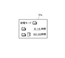
- the ECU 39 is set with a function of displaying the power supply available time that can be continuously supplied with the obtained current output power on the display surface 21a of the display device 21 as shown in FIG. 2A, for example.
- the power supply time is "Time” together with the "outside output amount” (outside output power) of the electric power supplied to the outside and the "vehicle use amount” (vehicle use power) of the electric power used by the vehicle itself. It is designed to be digitally displayed as "to Empty".
- FIG. 2A shows an example of display when, for example, only the electric power of the battery 17 is permitted to be supplied to the outside.
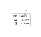
- the display surface 21a is individually attached to the display surface 21a, that is, the battery, for example, as shown in FIG. 2B.
- the power supply available time that can be continuously supplied to the outside by the electric power of 17 and the power supply available time that can be continuously supplied to the outside by the electric power generated by the engine operation are displayed respectively.
- the power supply available time by operating the engine is displayed as the time remaining for the time corresponding to the power consumption required for traveling a predetermined distance.
- the engine 13 at this time is operated at the rotation value set by the rotation speed setting unit 27.
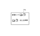
- the ECU 39 displays an alert in the power supply mode, for example, when the time when the power supply from the vehicle to the outside is stopped is approaching, a warning notifying that the power supply stop is near before the stop time, for example.
- a function is set to display an alert to the effect that "power supply is stopped after one hour" on the display surface 21a as shown in FIG.
- the ECU 39 causes the entire display surface 21a as shown in FIG. 4, for example, to blink, resulting in a large power consumption.
- a notification function is also set to notify that the power has changed.
- the ECU 39 can communicate with a mobile terminal with a display screen, for example, a smartphone 43 via a communication device 41 (for example, Bluetooth (registered trademark)), and the power supply available time displayed on the display surface 21a, an alert, and the like.
- the fluctuation of the power consumption is also displayed on the display screen (not shown) of the smartphone 43.
- the above information may be displayed on the smartphone 43 via Internet communication or a cloud 42 (external storage device).
- a cloud 42 external storage device
- the user parks the vehicle near the V2H device 10 of the house ⁇ , and connects the power supply cable 10a extending from the V2H device 10 to the charging / discharging port 9 of the vehicle. Then, the user selects from the display surface 21a of the display device 21 an external output only by the electric power of the battery 17 or an external output that integrates the electric power of the battery 17 and the electric power generated by the engine operation, and supplies the electric power to the outside. Execute power supply mode.
- the user sets a required distance (predetermined distance) from the distance setting unit 23 assuming refueling of the vehicle, or sets an upper limit value of the amount of electric energy supplied from the upper limit setting unit 25 to the outside.
- the engine speed is set from the rotation speed setting unit 27 in order to perform low noise and high efficiency operation of the engine operation.
- these set values may be unique values.
- a case where only the electric power of the battery 17 is supplied to the outside will be described as an example.
- the electric power of the battery 17 is supplied from the vehicle to the distribution board 51 of the house ⁇ via the power supply cable 10a and the V2H device 10.
- various electric devices such as home appliances such as lighting of the house ⁇ are used.
- the power supply available time that can be continuously supplied with the current output power as shown in FIG. 2A is digitally displayed on the display surface 21a as "Time to Empty". To.
- the power supply time is based on the current battery capacity, the latest usage amount (average), the set upper limit of the output power, the set predetermined distance, and the like.
- the power supply available time at this time is displayed together with the "outside output amount" supplied to the outside and the "vehicle usage amount” used by the vehicle, the current output status is easy to understand.
- the power supply available time that can be continuously supplied to the outside by the power from the battery 17 and the power generated by the engine 13 continue to the outside.
- the power supply available time that can be supplied is displayed respectively.
- the power supply possible time is a time considering the distance value input from the distance setting unit 23.
- the above information is also displayed on the display screen (not shown) of the smartphone 43.
- the power supply available time decreases.
- the time available for power supply can be extended as much as possible.
- the entire display surface 21a blinks as shown in FIG. 4, and the power consumption is significantly reduced. Notify that it has changed.
- the user recognizes that a situation has occurred in which the power supply time is suddenly reduced, and reviews the usage of the home electric appliance or changes the setting in the same manner as described above. As a result, the sharp decrease in the power supply time can be suppressed, and the use with a large power consumption can be suppressed.
- the power supply available time displayed on the display surface 21a reaches zero time, the power supply from the vehicle to the outside is stopped. At this time, the vehicle is in a state where it can run as much as it can be charged and refueled. Therefore, the vehicle can supply power to the house ⁇ again when it returns to the house ⁇ after traveling to the charging station or the refueling station with the remaining runnable power and fuel to charge and refuel.
- the limited electric power provided by the vehicle is effectively used in the house ⁇ .
- the user can easily know the change in the power supply possible time regardless of where the user is, that is, where the user is located. Moreover, since the displayed power supply possible time is the time left for the time corresponding to the power consumption that the vehicle can travel over a predetermined distance, even if the power supply possible time becomes zero time, the power supply to the outside is stopped. However, the vehicle can be charged and refueled by traveling to a station where it can be charged and refueled, and the ability to supply external power can be secured again.
- the predetermined distance can be set by the user by the distance setting unit 23, various situations can be easily dealt with.
- the predetermined distance in addition to the distance arbitrarily set by the user as described above and the preset distance, the power supply possible time becomes zero, such as the distance set by the user + ⁇ . However, it may be appropriately set within a range in which the state in which the vehicle can travel a predetermined distance or more is maintained.
- the output power is displayed on the display device 21 or the like together with the available power supply time, the user can easily grasp the current output power and use it as a guide when adjusting the use of the electric device being used. It can be used. Further, when the supply to the outside from the battery 17 and the supply of the generated power of the generator 13x by the engine operation (power generation system) to the outside are permitted, the display device 21 can continuously supply the power of the battery 17. Since the power supply available time and the power supply available time that can be continuously supplied by the engine operation are displayed, the user can easily grasp the current individual power supply status.
- the power supply time can be lengthened and the engine noise can be reduced to low noise. It is possible to suppress or operate the engine 13 with high efficiency.
- the power supply mode by notifying that the power consumption has fluctuated more than a predetermined value in the power supply mode, it is possible to grasp that the power supply available time has decreased sharply, and it is easy to suppress the sudden decrease in power consumption during the power supply available time. By doing so, it is possible to suppress a large change in the power supply available time.
- two types of power supply modes can be selected: power supply from the battery 17 and power supply from both the generator 13x and the battery 17 driven by the engine 13, but these two types are available. The user may be able to select either the power supply mode of the above or the power supply mode in which only the power generated by the generator 13x is supplied to the outside without supplying the power from the battery 17 to the outside.
- FIG. 5 is a power supply mode by the battery 17
- FIG. 6 is a display example of the power supply mode and the power supply possible time in the power supply mode by the battery 17 and the generator 13x.
- the present invention is not limited to the above-described embodiment, and may be varied and implemented within a range that does not deviate from the gist of the present invention.
- the present invention is applied to a PHEV vehicle, but it may be an EV vehicle or a fuel cell vehicle.
- the display device and the smartphone in the instrument are used for the display unit, other display devices may be used.
- the method of alert information and the method when the power consumption fluctuates significantly may be performed by other means.
Landscapes
- Engineering & Computer Science (AREA)
- Transportation (AREA)
- Mechanical Engineering (AREA)
- Power Engineering (AREA)
- Chemical & Material Sciences (AREA)
- Combustion & Propulsion (AREA)
- Life Sciences & Earth Sciences (AREA)
- Sustainable Development (AREA)
- Sustainable Energy (AREA)
- Automation & Control Theory (AREA)
- Electric Propulsion And Braking For Vehicles (AREA)
- Hybrid Electric Vehicles (AREA)
Priority Applications (1)
| Application Number | Priority Date | Filing Date | Title |
|---|---|---|---|
| JP2022536432A JPWO2022014655A1 (https=) | 2020-07-14 | 2021-07-14 |
Applications Claiming Priority (2)
| Application Number | Priority Date | Filing Date | Title |
|---|---|---|---|
| JP2020-120330 | 2020-07-14 | ||
| JP2020120330 | 2020-07-14 |
Publications (1)
| Publication Number | Publication Date |
|---|---|
| WO2022014655A1 true WO2022014655A1 (ja) | 2022-01-20 |
Family
ID=79555634
Family Applications (1)
| Application Number | Title | Priority Date | Filing Date |
|---|---|---|---|
| PCT/JP2021/026528 Ceased WO2022014655A1 (ja) | 2020-07-14 | 2021-07-14 | 電動車両 |
Country Status (2)
| Country | Link |
|---|---|
| JP (1) | JPWO2022014655A1 (https=) |
| WO (1) | WO2022014655A1 (https=) |
Cited By (1)
| Publication number | Priority date | Publication date | Assignee | Title |
|---|---|---|---|---|
| US20230313748A1 (en) * | 2022-04-05 | 2023-10-05 | Ford Global Technologies, Llc | Methods and systems of controlling a vehicle to support electrical loads external to the vehicle |
Citations (4)
| Publication number | Priority date | Publication date | Assignee | Title |
|---|---|---|---|---|
| JP2009278776A (ja) * | 2008-05-14 | 2009-11-26 | Toyota Motor Corp | 建物の電源システム |
| JP2013178884A (ja) * | 2012-02-28 | 2013-09-09 | Toyota Motor Corp | 電動車両、受電設備および電力供給システム |
| JP2016086551A (ja) * | 2014-10-27 | 2016-05-19 | トヨタ自動車株式会社 | 車両に搭載された燃料電池及び二次電池を利用して外部に電力を供給する外部給電システムの制御方法および外部給電システム |
| JP2018082536A (ja) * | 2016-11-15 | 2018-05-24 | トヨタ自動車株式会社 | 給電システムおよび車両 |
-
2021
- 2021-07-14 JP JP2022536432A patent/JPWO2022014655A1/ja active Pending
- 2021-07-14 WO PCT/JP2021/026528 patent/WO2022014655A1/ja not_active Ceased
Patent Citations (4)
| Publication number | Priority date | Publication date | Assignee | Title |
|---|---|---|---|---|
| JP2009278776A (ja) * | 2008-05-14 | 2009-11-26 | Toyota Motor Corp | 建物の電源システム |
| JP2013178884A (ja) * | 2012-02-28 | 2013-09-09 | Toyota Motor Corp | 電動車両、受電設備および電力供給システム |
| JP2016086551A (ja) * | 2014-10-27 | 2016-05-19 | トヨタ自動車株式会社 | 車両に搭載された燃料電池及び二次電池を利用して外部に電力を供給する外部給電システムの制御方法および外部給電システム |
| JP2018082536A (ja) * | 2016-11-15 | 2018-05-24 | トヨタ自動車株式会社 | 給電システムおよび車両 |
Cited By (1)
| Publication number | Priority date | Publication date | Assignee | Title |
|---|---|---|---|---|
| US20230313748A1 (en) * | 2022-04-05 | 2023-10-05 | Ford Global Technologies, Llc | Methods and systems of controlling a vehicle to support electrical loads external to the vehicle |
Also Published As
| Publication number | Publication date |
|---|---|
| JPWO2022014655A1 (https=) | 2022-01-20 |
Similar Documents
| Publication | Publication Date | Title |
|---|---|---|
| US10978888B2 (en) | Battery system for switching connection states of battery modules | |
| CN104859584B (zh) | 发电关闭警报 | |
| US8791666B2 (en) | Charging cable, vehicle, and vehicle charging system | |
| JP4769779B2 (ja) | 電気自動車の充電状態表示装置 | |
| US8981715B2 (en) | Charging cable for electric vehicle and method of controlling charging cable using determination of a charging cable usage history | |
| JP5372561B2 (ja) | 電気自動車の制御装置 | |
| EP3012145B1 (en) | Power supply device for auxiliary device battery | |
| JP5479999B2 (ja) | 車両の電源装置 | |
| US9884562B2 (en) | Vehicle power supply device | |
| US8874293B2 (en) | Climate control advisory system and method | |
| JP6103041B2 (ja) | 車両用電源装置 | |
| JP2011251648A (ja) | ハイブリッド車両の蓄電制御装置 | |
| JP5846210B2 (ja) | 車両および車両の制御方法 | |
| JP6137127B2 (ja) | 車両の電源装置 | |
| JP2020068573A (ja) | 車両 | |
| EP2402204B1 (en) | Electrically driven vehicle | |
| JP2013074658A (ja) | 電力切替装置 | |
| WO2022014655A1 (ja) | 電動車両 | |
| JP5900744B2 (ja) | 車両用給電システム | |
| JP7364513B2 (ja) | 外部給電装置付き自動車 | |
| JP2013112303A (ja) | ハイブリッドカーの電源装置 | |
| JP2012046121A (ja) | ハイブリッド車の発電制御装置 | |
| JP7538471B2 (ja) | 車両の制御装置 | |
| US20260116370A1 (en) | Systems and methods for charging an electric vehicle from multiple sources | |
| JP5958695B2 (ja) | 車両用給電システム |
Legal Events
| Date | Code | Title | Description |
|---|---|---|---|
| 121 | Ep: the epo has been informed by wipo that ep was designated in this application |
Ref document number: 21843376 Country of ref document: EP Kind code of ref document: A1 |
|
| ENP | Entry into the national phase |
Ref document number: 2022536432 Country of ref document: JP Kind code of ref document: A |
|
| NENP | Non-entry into the national phase |
Ref country code: DE |
|
| 122 | Ep: pct application non-entry in european phase |
Ref document number: 21843376 Country of ref document: EP Kind code of ref document: A1 |