WO2022014655A1 - Electric vehicle - Google Patents
Electric vehicle Download PDFInfo
- Publication number
- WO2022014655A1 WO2022014655A1 PCT/JP2021/026528 JP2021026528W WO2022014655A1 WO 2022014655 A1 WO2022014655 A1 WO 2022014655A1 JP 2021026528 W JP2021026528 W JP 2021026528W WO 2022014655 A1 WO2022014655 A1 WO 2022014655A1
- Authority
- WO
- WIPO (PCT)
- Prior art keywords
- power
- power supply
- vehicle
- electric
- outside
- Prior art date
Links
Images


Classifications
-
- B—PERFORMING OPERATIONS; TRANSPORTING
- B60—VEHICLES IN GENERAL
- B60K—ARRANGEMENT OR MOUNTING OF PROPULSION UNITS OR OF TRANSMISSIONS IN VEHICLES; ARRANGEMENT OR MOUNTING OF PLURAL DIVERSE PRIME-MOVERS IN VEHICLES; AUXILIARY DRIVES FOR VEHICLES; INSTRUMENTATION OR DASHBOARDS FOR VEHICLES; ARRANGEMENTS IN CONNECTION WITH COOLING, AIR INTAKE, GAS EXHAUST OR FUEL SUPPLY OF PROPULSION UNITS IN VEHICLES
- B60K6/00—Arrangement or mounting of plural diverse prime-movers for mutual or common propulsion, e.g. hybrid propulsion systems comprising electric motors and internal combustion engines ; Control systems therefor, i.e. systems controlling two or more prime movers, or controlling one of these prime movers and any of the transmission, drive or drive units Informative references: mechanical gearings with secondary electric drive F16H3/72; arrangements for handling mechanical energy structurally associated with the dynamo-electric machine H02K7/00; machines comprising structurally interrelated motor and generator parts H02K51/00; dynamo-electric machines not otherwise provided for in H02K see H02K99/00
- B60K6/20—Arrangement or mounting of plural diverse prime-movers for mutual or common propulsion, e.g. hybrid propulsion systems comprising electric motors and internal combustion engines ; Control systems therefor, i.e. systems controlling two or more prime movers, or controlling one of these prime movers and any of the transmission, drive or drive units Informative references: mechanical gearings with secondary electric drive F16H3/72; arrangements for handling mechanical energy structurally associated with the dynamo-electric machine H02K7/00; machines comprising structurally interrelated motor and generator parts H02K51/00; dynamo-electric machines not otherwise provided for in H02K see H02K99/00 the prime-movers consisting of electric motors and internal combustion engines, e.g. HEVs
- B60K6/22—Arrangement or mounting of plural diverse prime-movers for mutual or common propulsion, e.g. hybrid propulsion systems comprising electric motors and internal combustion engines ; Control systems therefor, i.e. systems controlling two or more prime movers, or controlling one of these prime movers and any of the transmission, drive or drive units Informative references: mechanical gearings with secondary electric drive F16H3/72; arrangements for handling mechanical energy structurally associated with the dynamo-electric machine H02K7/00; machines comprising structurally interrelated motor and generator parts H02K51/00; dynamo-electric machines not otherwise provided for in H02K see H02K99/00 the prime-movers consisting of electric motors and internal combustion engines, e.g. HEVs characterised by apparatus, components or means specially adapted for HEVs
-
- B—PERFORMING OPERATIONS; TRANSPORTING
- B60—VEHICLES IN GENERAL
- B60L—PROPULSION OF ELECTRICALLY-PROPELLED VEHICLES; SUPPLYING ELECTRIC POWER FOR AUXILIARY EQUIPMENT OF ELECTRICALLY-PROPELLED VEHICLES; ELECTRODYNAMIC BRAKE SYSTEMS FOR VEHICLES IN GENERAL; MAGNETIC SUSPENSION OR LEVITATION FOR VEHICLES; MONITORING OPERATING VARIABLES OF ELECTRICALLY-PROPELLED VEHICLES; ELECTRIC SAFETY DEVICES FOR ELECTRICALLY-PROPELLED VEHICLES
- B60L50/00—Electric propulsion with power supplied within the vehicle
- B60L50/10—Electric propulsion with power supplied within the vehicle using propulsion power supplied by engine-driven generators, e.g. generators driven by combustion engines
- B60L50/16—Electric propulsion with power supplied within the vehicle using propulsion power supplied by engine-driven generators, e.g. generators driven by combustion engines with provision for separate direct mechanical propulsion
-
- B—PERFORMING OPERATIONS; TRANSPORTING
- B60—VEHICLES IN GENERAL
- B60L—PROPULSION OF ELECTRICALLY-PROPELLED VEHICLES; SUPPLYING ELECTRIC POWER FOR AUXILIARY EQUIPMENT OF ELECTRICALLY-PROPELLED VEHICLES; ELECTRODYNAMIC BRAKE SYSTEMS FOR VEHICLES IN GENERAL; MAGNETIC SUSPENSION OR LEVITATION FOR VEHICLES; MONITORING OPERATING VARIABLES OF ELECTRICALLY-PROPELLED VEHICLES; ELECTRIC SAFETY DEVICES FOR ELECTRICALLY-PROPELLED VEHICLES
- B60L50/00—Electric propulsion with power supplied within the vehicle
- B60L50/50—Electric propulsion with power supplied within the vehicle using propulsion power supplied by batteries or fuel cells
- B60L50/60—Electric propulsion with power supplied within the vehicle using propulsion power supplied by batteries or fuel cells using power supplied by batteries
-
- B—PERFORMING OPERATIONS; TRANSPORTING
- B60—VEHICLES IN GENERAL
- B60L—PROPULSION OF ELECTRICALLY-PROPELLED VEHICLES; SUPPLYING ELECTRIC POWER FOR AUXILIARY EQUIPMENT OF ELECTRICALLY-PROPELLED VEHICLES; ELECTRODYNAMIC BRAKE SYSTEMS FOR VEHICLES IN GENERAL; MAGNETIC SUSPENSION OR LEVITATION FOR VEHICLES; MONITORING OPERATING VARIABLES OF ELECTRICALLY-PROPELLED VEHICLES; ELECTRIC SAFETY DEVICES FOR ELECTRICALLY-PROPELLED VEHICLES
- B60L53/00—Methods of charging batteries, specially adapted for electric vehicles; Charging stations or on-board charging equipment therefor; Exchange of energy storage elements in electric vehicles
- B60L53/10—Methods of charging batteries, specially adapted for electric vehicles; Charging stations or on-board charging equipment therefor; Exchange of energy storage elements in electric vehicles characterised by the energy transfer between the charging station and the vehicle
- B60L53/14—Conductive energy transfer
-
- B—PERFORMING OPERATIONS; TRANSPORTING
- B60—VEHICLES IN GENERAL
- B60L—PROPULSION OF ELECTRICALLY-PROPELLED VEHICLES; SUPPLYING ELECTRIC POWER FOR AUXILIARY EQUIPMENT OF ELECTRICALLY-PROPELLED VEHICLES; ELECTRODYNAMIC BRAKE SYSTEMS FOR VEHICLES IN GENERAL; MAGNETIC SUSPENSION OR LEVITATION FOR VEHICLES; MONITORING OPERATING VARIABLES OF ELECTRICALLY-PROPELLED VEHICLES; ELECTRIC SAFETY DEVICES FOR ELECTRICALLY-PROPELLED VEHICLES
- B60L55/00—Arrangements for supplying energy stored within a vehicle to a power network, i.e. vehicle-to-grid [V2G] arrangements
-
- B—PERFORMING OPERATIONS; TRANSPORTING
- B60—VEHICLES IN GENERAL
- B60L—PROPULSION OF ELECTRICALLY-PROPELLED VEHICLES; SUPPLYING ELECTRIC POWER FOR AUXILIARY EQUIPMENT OF ELECTRICALLY-PROPELLED VEHICLES; ELECTRODYNAMIC BRAKE SYSTEMS FOR VEHICLES IN GENERAL; MAGNETIC SUSPENSION OR LEVITATION FOR VEHICLES; MONITORING OPERATING VARIABLES OF ELECTRICALLY-PROPELLED VEHICLES; ELECTRIC SAFETY DEVICES FOR ELECTRICALLY-PROPELLED VEHICLES
- B60L58/00—Methods or circuit arrangements for monitoring or controlling batteries or fuel cells, specially adapted for electric vehicles
- B60L58/10—Methods or circuit arrangements for monitoring or controlling batteries or fuel cells, specially adapted for electric vehicles for monitoring or controlling batteries
-
- B—PERFORMING OPERATIONS; TRANSPORTING
- B60—VEHICLES IN GENERAL
- B60W—CONJOINT CONTROL OF VEHICLE SUB-UNITS OF DIFFERENT TYPE OR DIFFERENT FUNCTION; CONTROL SYSTEMS SPECIALLY ADAPTED FOR HYBRID VEHICLES; ROAD VEHICLE DRIVE CONTROL SYSTEMS FOR PURPOSES NOT RELATED TO THE CONTROL OF A PARTICULAR SUB-UNIT
- B60W10/00—Conjoint control of vehicle sub-units of different type or different function
- B60W10/24—Conjoint control of vehicle sub-units of different type or different function including control of energy storage means
- B60W10/26—Conjoint control of vehicle sub-units of different type or different function including control of energy storage means for electrical energy, e.g. batteries or capacitors
-
- B—PERFORMING OPERATIONS; TRANSPORTING
- B60—VEHICLES IN GENERAL
- B60W—CONJOINT CONTROL OF VEHICLE SUB-UNITS OF DIFFERENT TYPE OR DIFFERENT FUNCTION; CONTROL SYSTEMS SPECIALLY ADAPTED FOR HYBRID VEHICLES; ROAD VEHICLE DRIVE CONTROL SYSTEMS FOR PURPOSES NOT RELATED TO THE CONTROL OF A PARTICULAR SUB-UNIT
- B60W20/00—Control systems specially adapted for hybrid vehicles
-
- H—ELECTRICITY
- H02—GENERATION; CONVERSION OR DISTRIBUTION OF ELECTRIC POWER
- H02J—CIRCUIT ARRANGEMENTS OR SYSTEMS FOR SUPPLYING OR DISTRIBUTING ELECTRIC POWER; SYSTEMS FOR STORING ELECTRIC ENERGY
- H02J7/00—Circuit arrangements for charging or depolarising batteries or for supplying loads from batteries
-
- Y—GENERAL TAGGING OF NEW TECHNOLOGICAL DEVELOPMENTS; GENERAL TAGGING OF CROSS-SECTIONAL TECHNOLOGIES SPANNING OVER SEVERAL SECTIONS OF THE IPC; TECHNICAL SUBJECTS COVERED BY FORMER USPC CROSS-REFERENCE ART COLLECTIONS [XRACs] AND DIGESTS
- Y02—TECHNOLOGIES OR APPLICATIONS FOR MITIGATION OR ADAPTATION AGAINST CLIMATE CHANGE
- Y02T—CLIMATE CHANGE MITIGATION TECHNOLOGIES RELATED TO TRANSPORTATION
- Y02T10/00—Road transport of goods or passengers
- Y02T10/60—Other road transportation technologies with climate change mitigation effect
- Y02T10/70—Energy storage systems for electromobility, e.g. batteries
-
- Y—GENERAL TAGGING OF NEW TECHNOLOGICAL DEVELOPMENTS; GENERAL TAGGING OF CROSS-SECTIONAL TECHNOLOGIES SPANNING OVER SEVERAL SECTIONS OF THE IPC; TECHNICAL SUBJECTS COVERED BY FORMER USPC CROSS-REFERENCE ART COLLECTIONS [XRACs] AND DIGESTS
- Y02—TECHNOLOGIES OR APPLICATIONS FOR MITIGATION OR ADAPTATION AGAINST CLIMATE CHANGE
- Y02T—CLIMATE CHANGE MITIGATION TECHNOLOGIES RELATED TO TRANSPORTATION
- Y02T10/00—Road transport of goods or passengers
- Y02T10/60—Other road transportation technologies with climate change mitigation effect
- Y02T10/7072—Electromobility specific charging systems or methods for batteries, ultracapacitors, supercapacitors or double-layer capacitors
-
- Y—GENERAL TAGGING OF NEW TECHNOLOGICAL DEVELOPMENTS; GENERAL TAGGING OF CROSS-SECTIONAL TECHNOLOGIES SPANNING OVER SEVERAL SECTIONS OF THE IPC; TECHNICAL SUBJECTS COVERED BY FORMER USPC CROSS-REFERENCE ART COLLECTIONS [XRACs] AND DIGESTS
- Y02—TECHNOLOGIES OR APPLICATIONS FOR MITIGATION OR ADAPTATION AGAINST CLIMATE CHANGE
- Y02T—CLIMATE CHANGE MITIGATION TECHNOLOGIES RELATED TO TRANSPORTATION
- Y02T90/00—Enabling technologies or technologies with a potential or indirect contribution to GHG emissions mitigation
- Y02T90/10—Technologies relating to charging of electric vehicles
- Y02T90/14—Plug-in electric vehicles
Definitions
- the present invention relates to an electric vehicle capable of supplying electric power to the outside.
- the power from the vehicle-mounted drive battery or the power generation system generated by the vehicle-mounted engine is generated through the connection part provided in the vehicle body.
- power is supplied to the outside, for example, a house (see, for example, Patent Document 1).
- Such power supply from the vehicle to the outside is effective in a situation where the city power supply is stopped at the time of a disaster.
- an object of the present invention is to provide an electric vehicle capable of easily grasping the power supply possible time in the power supply mode in which electric power is supplied from the vehicle to the outside.
- the electric vehicle of the present invention is an electric vehicle having a connection portion capable of supplying electric power to the outside of the vehicle, and is currently in a power supply mode in which electric power is supplied to the outside through the connection portion. It is characterized by having a control unit that calculates a power supply available time that can be continuously supplied with the output power of the above, and a display unit that displays the power supply available time calculated by the control unit.
- the control unit may calculate the power supply available time based on the predetermined distance so that the state in which the vehicle can travel a predetermined distance or more is maintained even if the power supply available time becomes zero.
- the vehicle can travel a predetermined distance or longer even when the power supply time becomes zero, so that the vehicle can be charged and refueled by traveling to a station where charging and refueling are possible, and power is supplied to the outside again.
- the predetermined distance may be set by the user. This makes it possible to display the power supply available time according to the usage environment of the vehicle, the preference of the user, and the like, and it is possible to improve the usability.
- the output power is simultaneously displayed on the display unit together with the power supply available time. This allows the user to grasp the power supply available time and confirm the power that can be output.
- the output power includes the out-of-vehicle output power supplied to the outside of the vehicle and the vehicle-used power used by the vehicle itself, and the display unit shows the out-of-vehicle output power and the vehicle. It is preferable that the power consumption is displayed separately.
- the vehicle comprises a battery that stores electricity and a power generation system that uses fuel to generate electricity, either or both of the power supply from the battery and the power generation system.
- the control unit can select and supply power to the outside, and the control unit has the power supply available time in which power can be supplied only by the battery, the power supply available time in which power can be supplied only by the power generation system, and the battery. It is preferable to display each of the power supply available times during which power can be supplied by both the power generation system and the power generation system on the display unit individually or in combination according to the selection.
- the user can confirm the power supply available time that can supply power only by the battery, the power supply available time that can supply power only by the power generation system, and the power supply available time that can supply power by both the battery and the power generation system. It becomes possible to judge whether or not the power generation system needs to be operated.
- the display unit may include a mobile terminal device capable of communicating with the vehicle.
- the control unit may display the power supply available time on the mobile terminal device capable of communicating with the vehicle.
- control unit may display an alert on the display unit before a predetermined time when the supply of electric power to the outside is stopped.
- the user can change the power usage status to extend the power supply available time before the predetermined time when the power supply to the outside is stopped.
- control unit may notify the display unit when the output power supplied to the outside fluctuates by a predetermined value or more.
- the user can know the fluctuation of the output power more than a predetermined value, and it is possible to suppress the fluctuation of the output power, particularly the increase of the output power, and to suppress the drastic change of the power supply possible time. ..
- it may further have an upper limit setting unit for setting an upper limit value of the out-of-vehicle output power supplied to the outside of the vehicle.
- an upper limit setting unit for setting an upper limit value of the out-of-vehicle output power supplied to the outside of the vehicle.
- the power supply available time that can be continuously supplied with the current output power is calculated and displayed on the display unit. Therefore, the user can easily grasp the power supply possible time when the power supply is continued with the current output power by visually observing the display unit. Therefore, based on the displayed power supply available time, the user can easily devise ways such as changing the usage of the electric equipment being used to extend the power supply available time, and from a limited number of vehicles.
- the power supply can be used effectively. This is especially effective when the power outage lasts for a long time.
- (A) is a block diagram showing each part of an electric vehicle according to an embodiment of the present invention
- (b) is a front view showing a display part
- (c) is a block diagram showing a system displaying a power supply possible time.
- the front view which shows an example of the display information displayed on the display part.
- the front view which shows an example of the display information displayed on the display part.
- the front view of the display part which shows the display example of the display information when the power supply mode by a battery is selected.
- the front view of the display part which shows the display example of the display information when the power supply mode by a battery is selected.
- the front view of the display part which shows the display example of the display information when the power supply mode by both a battery and a generator is selected.
- the front view of the display part which shows the display example of the display information when the power supply mode by both a battery and a generator is selected.
- the front view of the display part which shows the display example of the display information when the power supply mode by both a battery and a generator is selected.
- the front view of the display part which shows the display example of the display information when the power supply mode by both a battery and a generator is selected.
- FIG. 1A shows each part of an electric vehicle, for example, a PHEV vehicle (hereinafter referred to as a vehicle) capable of traveling in which EV traveling or series traveling occupies a large part.
- a vehicle PHEV vehicle
- Reference numeral 1 in FIG. 1A is a vehicle body
- 3 is a vehicle compartment formed in the vehicle body 1
- 5 is a power unit chamber formed in the front portion of the vehicle body 1
- 7 is an instrument panel provided in the vehicle compartment 3.
- 9 indicate a charging / discharging port provided on the side of the vehicle body 1.
- 1x indicates a front wheel
- 1y indicates a rear wheel
- 1z indicates a steering wheel.
- the charging / discharging port 9 is a component that can be connected to a charging cable (not shown) or a power feeding cable 10a extending from a V2H device 10 installed in an external house ⁇ .
- a charging cable (not shown) is connected to the charging / discharging port 9, the battery 17 can be charged from an external charging facility (not shown).
- the power supply cable 10a of the V2H device 10 is connected, the electric power stored in the battery 17 and the electric power generated by the generator 13x can be supplied to the house ⁇ .
- the instrument panel 7 is provided with an outlet 7a that allows the electric power of the battery 17 and the generated electric power to be directly supplied to an electric device such as a home electric appliance. That is, the charging / discharging port 9 and the outlet 7a constitute a connection portion capable of supplying power from the vehicle to the outside in the present application. Further, the instrument panel 7 is provided with a binocular meter panel 19 as shown in FIG. 1 (b), for example. A display device 21 (corresponding to the display unit of the present application) is provided in a part of the meter panel 19, for example, in the central portion.
- the display device 21 includes a display surface 21a that can be visually recognized by a user such as a driver, a display circuit unit (not shown) that displays different images on the display surface 21a, and a switch unit that switches the display image for each switch operation (not shown). (Not shown) and so on.
- the display device 21 integrates EV driving, hybrid driving (series), charging mode, power supply mode using only the battery 17, and power generation by the battery 17 and the generator 13x (from both the battery 17 and the generator 13x). (Power can be supplied)
- the power supply mode, etc. are displayed. Further, various modes displayed on the display device 21 can be selected by a touch sensor (not shown).
- an image showing the remaining amount of the battery 17 by using a part of the display surface 21a an image showing the remaining amount of fuel required for operating the engine 13, or when only EV driving is performed. Images showing the cruising range and the cruising range when EV driving and power generation driving are integrated are displayed.
- a distance setting unit 23 for ensuring (setting) traveling for the minimum necessary distance such as a predetermined distance from the current position to a place where refueling can be performed, and a charging / discharging port.
- An upper limit setting unit 25 for setting an upper limit value of the amount of electric power supplied from the 9 or the outlet 7a to the outside, a rotation speed setting unit 27 for setting the engine rotation speed when the engine 13 generates electricity, and the like are provided. ing.
- the current output power in the power supply mode from the vehicle to the outside is used, for example, by using a control device for controlling the battery 17 and integrated control of the vehicle shown in FIG. 1 (c). It is equipped with a control system 31 that displays the power supply available time that can be continuously supplied.
- control system 31 that displays the power supply available time that can be continuously supplied.
- reference numeral 37 in FIG. 1C is a BMU that monitors and controls the battery 17, and reference numeral 39 is an ECU that integrally controls the vehicle.
- the BMU (Battery Management Unit) 37 has a function of detecting the remaining amount of the battery 17 based on output information from various sensors of the battery 17, and is used from the current battery 17 in the power supply mode from the vehicle to the outside. It has a function to detect the amount.
- the BMU 37 is connected to the battery 17, the inverter 11a, the charging / discharging port 9, the outlet 7a, and the like.
- the ECU (Electronic Control Unit) 39 (control unit) is external from EV driving, hybrid driving (series driving), charging mode, and battery 17 only, based on information from, for example, BMU 37 and information set by various setting units. It has a function to execute a power supply mode for supplying power to the outside and a power supply mode for supplying the output power from the battery 17 and the generated power of the generator 13x to the outside.
- the ECU 39 is set with a function of obtaining the latest power consumption (average) usage amount in the power supply mode in which power is supplied from the vehicle to the outside. Further, the ECU 39 is set with a function of calculating the feedable time that can be continuously supplied with the current output power in the same power supply mode.
- This power supply possible time is a distance value set by the distance setting unit 23, for example, based on the power supplied from the vehicle to the outside and the latest power consumption (average) so that the vehicle can travel a predetermined distance after the power supply mode is stopped. For example, the power consumption required for traveling from the current position to the place where refueling can be performed is obtained, and the time obtained by subtracting the time corresponding to the same power consumption from the total power supply available time is used.
- the value set by the upper limit setting unit 25 is used as the current upper limit value of the output power.
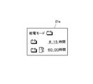
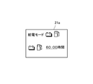
- the ECU 39 is set with a function of displaying the power supply available time that can be continuously supplied with the obtained current output power on the display surface 21a of the display device 21 as shown in FIG. 2A, for example.
- the power supply time is "Time” together with the "outside output amount” (outside output power) of the electric power supplied to the outside and the "vehicle use amount” (vehicle use power) of the electric power used by the vehicle itself. It is designed to be digitally displayed as "to Empty".
- FIG. 2A shows an example of display when, for example, only the electric power of the battery 17 is permitted to be supplied to the outside.
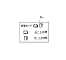
- the display surface 21a is individually attached to the display surface 21a, that is, the battery, for example, as shown in FIG. 2B.
- the power supply available time that can be continuously supplied to the outside by the electric power of 17 and the power supply available time that can be continuously supplied to the outside by the electric power generated by the engine operation are displayed respectively.
- the power supply available time by operating the engine is displayed as the time remaining for the time corresponding to the power consumption required for traveling a predetermined distance.
- the engine 13 at this time is operated at the rotation value set by the rotation speed setting unit 27.
- the ECU 39 displays an alert in the power supply mode, for example, when the time when the power supply from the vehicle to the outside is stopped is approaching, a warning notifying that the power supply stop is near before the stop time, for example.
- a function is set to display an alert to the effect that "power supply is stopped after one hour" on the display surface 21a as shown in FIG.
- the ECU 39 causes the entire display surface 21a as shown in FIG. 4, for example, to blink, resulting in a large power consumption.
- a notification function is also set to notify that the power has changed.
- the ECU 39 can communicate with a mobile terminal with a display screen, for example, a smartphone 43 via a communication device 41 (for example, Bluetooth (registered trademark)), and the power supply available time displayed on the display surface 21a, an alert, and the like.
- the fluctuation of the power consumption is also displayed on the display screen (not shown) of the smartphone 43.
- the above information may be displayed on the smartphone 43 via Internet communication or a cloud 42 (external storage device).
- a cloud 42 external storage device
- the user parks the vehicle near the V2H device 10 of the house ⁇ , and connects the power supply cable 10a extending from the V2H device 10 to the charging / discharging port 9 of the vehicle. Then, the user selects from the display surface 21a of the display device 21 an external output only by the electric power of the battery 17 or an external output that integrates the electric power of the battery 17 and the electric power generated by the engine operation, and supplies the electric power to the outside. Execute power supply mode.
- the user sets a required distance (predetermined distance) from the distance setting unit 23 assuming refueling of the vehicle, or sets an upper limit value of the amount of electric energy supplied from the upper limit setting unit 25 to the outside.
- the engine speed is set from the rotation speed setting unit 27 in order to perform low noise and high efficiency operation of the engine operation.
- these set values may be unique values.
- a case where only the electric power of the battery 17 is supplied to the outside will be described as an example.
- the electric power of the battery 17 is supplied from the vehicle to the distribution board 51 of the house ⁇ via the power supply cable 10a and the V2H device 10.
- various electric devices such as home appliances such as lighting of the house ⁇ are used.
- the power supply available time that can be continuously supplied with the current output power as shown in FIG. 2A is digitally displayed on the display surface 21a as "Time to Empty". To.
- the power supply time is based on the current battery capacity, the latest usage amount (average), the set upper limit of the output power, the set predetermined distance, and the like.
- the power supply available time at this time is displayed together with the "outside output amount" supplied to the outside and the "vehicle usage amount” used by the vehicle, the current output status is easy to understand.
- the power supply available time that can be continuously supplied to the outside by the power from the battery 17 and the power generated by the engine 13 continue to the outside.
- the power supply available time that can be supplied is displayed respectively.
- the power supply possible time is a time considering the distance value input from the distance setting unit 23.
- the above information is also displayed on the display screen (not shown) of the smartphone 43.
- the power supply available time decreases.
- the time available for power supply can be extended as much as possible.
- the entire display surface 21a blinks as shown in FIG. 4, and the power consumption is significantly reduced. Notify that it has changed.
- the user recognizes that a situation has occurred in which the power supply time is suddenly reduced, and reviews the usage of the home electric appliance or changes the setting in the same manner as described above. As a result, the sharp decrease in the power supply time can be suppressed, and the use with a large power consumption can be suppressed.
- the power supply available time displayed on the display surface 21a reaches zero time, the power supply from the vehicle to the outside is stopped. At this time, the vehicle is in a state where it can run as much as it can be charged and refueled. Therefore, the vehicle can supply power to the house ⁇ again when it returns to the house ⁇ after traveling to the charging station or the refueling station with the remaining runnable power and fuel to charge and refuel.
- the limited electric power provided by the vehicle is effectively used in the house ⁇ .
- the user can easily know the change in the power supply possible time regardless of where the user is, that is, where the user is located. Moreover, since the displayed power supply possible time is the time left for the time corresponding to the power consumption that the vehicle can travel over a predetermined distance, even if the power supply possible time becomes zero time, the power supply to the outside is stopped. However, the vehicle can be charged and refueled by traveling to a station where it can be charged and refueled, and the ability to supply external power can be secured again.
- the predetermined distance can be set by the user by the distance setting unit 23, various situations can be easily dealt with.
- the predetermined distance in addition to the distance arbitrarily set by the user as described above and the preset distance, the power supply possible time becomes zero, such as the distance set by the user + ⁇ . However, it may be appropriately set within a range in which the state in which the vehicle can travel a predetermined distance or more is maintained.
- the output power is displayed on the display device 21 or the like together with the available power supply time, the user can easily grasp the current output power and use it as a guide when adjusting the use of the electric device being used. It can be used. Further, when the supply to the outside from the battery 17 and the supply of the generated power of the generator 13x by the engine operation (power generation system) to the outside are permitted, the display device 21 can continuously supply the power of the battery 17. Since the power supply available time and the power supply available time that can be continuously supplied by the engine operation are displayed, the user can easily grasp the current individual power supply status.
- the power supply time can be lengthened and the engine noise can be reduced to low noise. It is possible to suppress or operate the engine 13 with high efficiency.
- the power supply mode by notifying that the power consumption has fluctuated more than a predetermined value in the power supply mode, it is possible to grasp that the power supply available time has decreased sharply, and it is easy to suppress the sudden decrease in power consumption during the power supply available time. By doing so, it is possible to suppress a large change in the power supply available time.
- two types of power supply modes can be selected: power supply from the battery 17 and power supply from both the generator 13x and the battery 17 driven by the engine 13, but these two types are available. The user may be able to select either the power supply mode of the above or the power supply mode in which only the power generated by the generator 13x is supplied to the outside without supplying the power from the battery 17 to the outside.
- FIG. 5 is a power supply mode by the battery 17
- FIG. 6 is a display example of the power supply mode and the power supply possible time in the power supply mode by the battery 17 and the generator 13x.
- the present invention is not limited to the above-described embodiment, and may be varied and implemented within a range that does not deviate from the gist of the present invention.
- the present invention is applied to a PHEV vehicle, but it may be an EV vehicle or a fuel cell vehicle.
- the display device and the smartphone in the instrument are used for the display unit, other display devices may be used.
- the method of alert information and the method when the power consumption fluctuates significantly may be performed by other means.
Abstract
The present invention is an electric vehicle having a socket (7a) and a charge/discharge port (9) capable of supplying power to the exterior of the vehicle, wherein said electric vehicle additionally includes: an ECU that calculates a power supply availability time during which is it possible to continuously supply power at the current output power when in a power supply mode in which power is supplied to the exterior via the socket (7a) or the charge/discharge port (9); and a display device (21) for displaying the calculated power supply availability time. This configuration enables a user to easily ascertain the power supply availability time when the supply of power is continued at the current power use amount by simply viewing the power supply availability time displayed by the display device (21).
Description
本発明は、電力を外部へ供給可能な電動車両に関する。
The present invention relates to an electric vehicle capable of supplying electric power to the outside.
電動車両(PHEV(Plug-in Hybrid Electrical Vehicle),EV(Electric Vehicle)など)には、車体に設けられた接続部を通して、車載の駆動用バッテリからの電力や、車載エンジンで発電される発電システムからの電力を、外部、例えば住宅などに給電されるようにした仕様がある(例えば特許文献1などを参照)。
こうした車両から外部への電力供給は、災害時の市中電源が停止している状況下等において有効である。 For electric vehicles (PHEV (Plug-in Hybrid Electrical Vehicle), EV (Electric Vehicle), etc.), the power from the vehicle-mounted drive battery or the power generation system generated by the vehicle-mounted engine is generated through the connection part provided in the vehicle body. There is a specification that power is supplied to the outside, for example, a house (see, for example, Patent Document 1).
Such power supply from the vehicle to the outside is effective in a situation where the city power supply is stopped at the time of a disaster.
しかしながら、こうした車両は、外部への電力供給が不能な電動車両のように、バッテリ及び燃料の残量表示や、バッテリあるいは燃料を動力源としたときの航続可能距離が表示されたとしても、現在の出力電力で、外部機器をどれだけ使い続けられるかは把握することが困難である。
特に災害時は、先が見えない状況下にあるので、どれだけ家電機器が使い続けられるか把握することが重要である。 However, such vehicles are currently displayed, such as electric vehicles that cannot supply electric power to the outside, even if the remaining amount of battery and fuel is displayed and the cruising range when the battery or fuel is used as a power source is displayed. It is difficult to know how long the external device can be used with the output power of.
Especially in the event of a disaster, it is difficult to see the future, so it is important to understand how long home appliances can continue to be used.
そこで、本発明の目的は、車両から外部へ電力を供給する給電モード時に、容易に給電可能時間の把握ができる電動車両を提供することにある。
Therefore, an object of the present invention is to provide an electric vehicle capable of easily grasping the power supply possible time in the power supply mode in which electric power is supplied from the vehicle to the outside.
上記の目的を達成するため、本発明の電動車両は、車両の外部へ電力を供給可能な接続部を有する電動車両であって、前記接続部を通して電力が外部へ供給される給電モード時に、現在の出力電力で継続して供給可能な給電可能時間を演算する制御部と、前記制御部によって演算された前記給電可能時間が表示される表示部と、を有することを特徴とする。
In order to achieve the above object, the electric vehicle of the present invention is an electric vehicle having a connection portion capable of supplying electric power to the outside of the vehicle, and is currently in a power supply mode in which electric power is supplied to the outside through the connection portion. It is characterized by having a control unit that calculates a power supply available time that can be continuously supplied with the output power of the above, and a display unit that displays the power supply available time calculated by the control unit.
これにより、車両から電力を外部へ供給する給電モード時に、現在の出力電力で継続して供給可能な給電可能時間が制御部によって演算され表示部に表示される。
よって、使用者は表示部に表示された給電可能時間を目視することで、現在の出力電力で給電を継続した場合の給電可能時間を容易に把握することができる。
好ましくは、前記制御部は、前記給電可能時間がゼロとなっても前記車両が所定距離以上を走行可能な状態が維持されるよう前記所定距離に基づいて前記給電可能時間を演算するとよい。 As a result, in the power supply mode in which the power is supplied from the vehicle to the outside, the power supply possible time that can be continuously supplied with the current output power is calculated by the control unit and displayed on the display unit.
Therefore, the user can easily grasp the power supply possible time when the power supply is continued with the current output power by visually observing the power supply possible time displayed on the display unit.
Preferably, the control unit may calculate the power supply available time based on the predetermined distance so that the state in which the vehicle can travel a predetermined distance or more is maintained even if the power supply available time becomes zero.
これにより、給電可能時間がゼロとなっても車両が所定距離以上を走行可能であるので、例えば充電や給油が可能なステーションまで走行して充電、給油を行うことができ、再び外部への給電を可能にすることができる。
好ましくは、前記所定距離は、使用者によって設定可能であるとよい。
これにより、車両の使用環境や使用者の嗜好等に対応した給電可能時間の表示が可能になり、使用性を向上させることができる。 As a result, the vehicle can travel a predetermined distance or longer even when the power supply time becomes zero, so that the vehicle can be charged and refueled by traveling to a station where charging and refueling are possible, and power is supplied to the outside again. Can be made possible.
Preferably, the predetermined distance may be set by the user.
This makes it possible to display the power supply available time according to the usage environment of the vehicle, the preference of the user, and the like, and it is possible to improve the usability.
好ましくは、前記表示部には、前記給電可能時間とともに前記出力電力が同時に表示されるとよい。
これにより、使用者が、給電可能時間の把握とともに出力可能な電力を確認することができる。
好ましくは、前記出力電力は、前記車両の外部へ供給されている車外出力電力と、前記車両自身で使用している車両使用電力とを含み、前記表示部には、前記車外出力電力と前記車両使用電力とが別々で表示されるとよい。 Preferably, the output power is simultaneously displayed on the display unit together with the power supply available time.
This allows the user to grasp the power supply available time and confirm the power that can be output.
Preferably, the output power includes the out-of-vehicle output power supplied to the outside of the vehicle and the vehicle-used power used by the vehicle itself, and the display unit shows the out-of-vehicle output power and the vehicle. It is preferable that the power consumption is displayed separately.
これにより、使用者が車外出力電力と車両使用電力を別々に把握することができる。
好ましくは、前記車両は、電力を蓄電するバッテリと、燃料を使用して電力を発生させる発電システムとを備え、前記バッテリからの電力供給と前記発電システムからの電力供給の何れか一方または両方を選択して外部へ電力を供給可能とされ、前記制御部は、前記バッテリのみで電力を供給可能な前記給電可能時間と、前記発電システムのみで電力を供給可能な前記給電可能時間と、前記バッテリと前記発電システムの両方で電力を供給可能な前記給電可能時間のそれぞれを、前記選択に応じて単独または組み合わせて前記表示部に表示させるとよい。 As a result, the user can grasp the output power outside the vehicle and the power used by the vehicle separately.
Preferably, the vehicle comprises a battery that stores electricity and a power generation system that uses fuel to generate electricity, either or both of the power supply from the battery and the power generation system. The control unit can select and supply power to the outside, and the control unit has the power supply available time in which power can be supplied only by the battery, the power supply available time in which power can be supplied only by the power generation system, and the battery. It is preferable to display each of the power supply available times during which power can be supplied by both the power generation system and the power generation system on the display unit individually or in combination according to the selection.
これにより、バッテリのみで電力を供給可能な給電可能時間と、発電システムのみで電力を供給可能な給電可能時間と、バッテリと発電システムの両方で電力を供給可能な給電可能時間を使用者が確認することができ、発電システムの作動の要否を判断することが可能になる。
好ましくは、前記表示部は、前記車両と通信可能な携帯端末機器を含むとよい。
好ましくは、前記制御部は、前記車両と通信可能な携帯端末機器に前記給電可能時間を表示させるとよい。 As a result, the user can confirm the power supply available time that can supply power only by the battery, the power supply available time that can supply power only by the power generation system, and the power supply available time that can supply power by both the battery and the power generation system. It becomes possible to judge whether or not the power generation system needs to be operated.
Preferably, the display unit may include a mobile terminal device capable of communicating with the vehicle.
Preferably, the control unit may display the power supply available time on the mobile terminal device capable of communicating with the vehicle.
これにより、使用者の所在場所に関わらず、容易に給電可能時間を知ることができる。
好ましくは、前記制御部は、外部への電力の供給が停止される所定時間前に、前記表示部にアラートを表示するとよい。
これにより、外部への電力の供給が停止される所定時間前に、使用者が電力の使用状況を変更して、給電可能時間を延ばすように調整することができる。 This makes it possible to easily know the power supply available time regardless of the location of the user.
Preferably, the control unit may display an alert on the display unit before a predetermined time when the supply of electric power to the outside is stopped.
As a result, the user can change the power usage status to extend the power supply available time before the predetermined time when the power supply to the outside is stopped.
好ましくは、前記制御部は、外部に供給する出力電力に所定以上の変動があった場合に、前記表示部に報知するとよい。
これにより、使用者が所定以上の出力電力の変動を知ることができ、出力電力の変動、特に出力電力の増加を抑えるように対応して、給電可能時間の大幅な変化を抑制することができる。 Preferably, the control unit may notify the display unit when the output power supplied to the outside fluctuates by a predetermined value or more.
As a result, the user can know the fluctuation of the output power more than a predetermined value, and it is possible to suppress the fluctuation of the output power, particularly the increase of the output power, and to suppress the drastic change of the power supply possible time. ..
好ましくは、前記車両の外部へ供給される車外出力電力の上限値を設定する上限設定部をさらに有するとよい。
これにより、車外出力電力を抑制して、給電可能時間の大幅な減少を抑制することができる。 Preferably, it may further have an upper limit setting unit for setting an upper limit value of the out-of-vehicle output power supplied to the outside of the vehicle.
As a result, it is possible to suppress the output power outside the vehicle and suppress a significant decrease in the power supply possible time.
本発明の電動車両によれば、車両から電力を外部へ供給する給電モード時に、現在の出力電力で継続して供給可能な給電可能時間が演算されて表示部に表示される。
よって、使用者は表示部を目視することで、現在の出力電力で給電を続けた場合の給電可能時間を容易に把握することができる。
それ故、使用者は、表示された給電可能時間に基づき、例えば利用している電気機器の使い方を変えるなど、どれだけ給電可能時間を長くできるなど工夫が容易に行なえ、限られた車両からの給電電力を有効に利用することができる。特に停電が長期化に及ぶような場合には有効である。 According to the electric vehicle of the present invention, in the power supply mode in which power is supplied from the vehicle to the outside, the power supply available time that can be continuously supplied with the current output power is calculated and displayed on the display unit.
Therefore, the user can easily grasp the power supply possible time when the power supply is continued with the current output power by visually observing the display unit.
Therefore, based on the displayed power supply available time, the user can easily devise ways such as changing the usage of the electric equipment being used to extend the power supply available time, and from a limited number of vehicles. The power supply can be used effectively. This is especially effective when the power outage lasts for a long time.
以下、本発明を図1~図6に示す実施形態にもとづいて説明する。
図1(a)は、電動車両、例えばEV走行やシリーズ走行が多くを占める走行を可能としたPHEV車(以下、車両という)の各部を示している。
図1(a)中の符号1は車体、3は車体1内に形成された車室、5は車体1の前部に形成されたパワーユニット室、7は車室3内に設けたインストルメントパネル、9は車体1の側部に設けた充電/放電口を示している。ちなみに、1xは前輪、1yは後輪、1zはハンドルを示している。 Hereinafter, the present invention will be described with reference to the embodiments shown in FIGS. 1 to 6.
FIG. 1A shows each part of an electric vehicle, for example, a PHEV vehicle (hereinafter referred to as a vehicle) capable of traveling in which EV traveling or series traveling occupies a large part.
Reference numeral 1 in FIG. 1A is a vehicle body, 3 is a vehicle compartment formed in thevehicle body 1, 5 is a power unit chamber formed in the front portion of the vehicle body 1, and 7 is an instrument panel provided in the vehicle compartment 3. , 9 indicate a charging / discharging port provided on the side of the vehicle body 1. By the way, 1x indicates a front wheel, 1y indicates a rear wheel, and 1z indicates a steering wheel.
図1(a)は、電動車両、例えばEV走行やシリーズ走行が多くを占める走行を可能としたPHEV車(以下、車両という)の各部を示している。
図1(a)中の符号1は車体、3は車体1内に形成された車室、5は車体1の前部に形成されたパワーユニット室、7は車室3内に設けたインストルメントパネル、9は車体1の側部に設けた充電/放電口を示している。ちなみに、1xは前輪、1yは後輪、1zはハンドルを示している。 Hereinafter, the present invention will be described with reference to the embodiments shown in FIGS. 1 to 6.
FIG. 1A shows each part of an electric vehicle, for example, a PHEV vehicle (hereinafter referred to as a vehicle) capable of traveling in which EV traveling or series traveling occupies a large part.
Reference numeral 1 in FIG. 1A is a vehicle body, 3 is a vehicle compartment formed in the
例えばパワーユニット室5内には、前輪1xを駆動するモータ11や、モータ11につながるインバータ11aや、燃料を使用して作動するエンジン13を駆動源として発電するジェネレータ13x(本願の発電システムに相当)などが収められている。また車体1の下部には蓄電可能なバッテリ17が設けられている。そして、ジェネレータ13xで発電された電力がバッテリ17へ入力されたり、バッテリ17からの電力がインバータ11aを介してモータ11へ出力されたりする。
For example, in the power unit chamber 5, a motor 11 that drives the front wheels 1x, an inverter 11a connected to the motor 11, and a generator 13x that generates electricity using a fuel-operated engine 13 as a drive source (corresponding to the power generation system of the present application). Etc. are stored. Further, a battery 17 capable of storing electricity is provided in the lower part of the vehicle body 1. Then, the electric power generated by the generator 13x is input to the battery 17, and the electric power from the battery 17 is output to the motor 11 via the inverter 11a.
充電/放電口9は、充電ケーブル(図示しない)や外部である住宅αに据え付けたV2H機器10から延びる給電ケーブル10aと接続可能な部品である。
この充電/放電口9は、充電ケーブル(図示しない)が接続されると、外部充電設備(図示しない)からバッテリ17へ充電可能とされる。V2H機器10の給電ケーブル10aが接続されると、バッテリ17に蓄えられた電力やジェネレータ13xで発電された電力が住宅αへ給電可能とされるものである。 The charging / dischargingport 9 is a component that can be connected to a charging cable (not shown) or a power feeding cable 10a extending from a V2H device 10 installed in an external house α.
When a charging cable (not shown) is connected to the charging / dischargingport 9, the battery 17 can be charged from an external charging facility (not shown). When the power supply cable 10a of the V2H device 10 is connected, the electric power stored in the battery 17 and the electric power generated by the generator 13x can be supplied to the house α.
この充電/放電口9は、充電ケーブル(図示しない)が接続されると、外部充電設備(図示しない)からバッテリ17へ充電可能とされる。V2H機器10の給電ケーブル10aが接続されると、バッテリ17に蓄えられた電力やジェネレータ13xで発電された電力が住宅αへ給電可能とされるものである。 The charging / discharging
When a charging cable (not shown) is connected to the charging / discharging
インストルメントパネル7には、バッテリ17の電力や発電電力が直接、家電機器など電気機器へ供給可能とするコンセント7aが設けられている。
つまり、充電/放電口9やコンセント7aは、本願における車両から外部へ給電可能な接続部を構成している。
またインストルメントパネル7には、例えば図1(b)に示されるように二眼形のメーターパネル19が設けられている。このメーターパネル19の一部、例えば中央部にディスプレイ装置21(本願の表示部に相当)が設けられている。ディスプレイ装置21は、運転者等の使用者が視認可能な表示面21aや、表示面21aにそれぞれ異なる画像を表示させる表示回路部(図示しない)や、表示画像をスイッチ操作毎に切り換えるスイッチ部(図示しない)などを有している。 Theinstrument panel 7 is provided with an outlet 7a that allows the electric power of the battery 17 and the generated electric power to be directly supplied to an electric device such as a home electric appliance.
That is, the charging / dischargingport 9 and the outlet 7a constitute a connection portion capable of supplying power from the vehicle to the outside in the present application.
Further, theinstrument panel 7 is provided with a binocular meter panel 19 as shown in FIG. 1 (b), for example. A display device 21 (corresponding to the display unit of the present application) is provided in a part of the meter panel 19, for example, in the central portion. The display device 21 includes a display surface 21a that can be visually recognized by a user such as a driver, a display circuit unit (not shown) that displays different images on the display surface 21a, and a switch unit that switches the display image for each switch operation (not shown). (Not shown) and so on.
つまり、充電/放電口9やコンセント7aは、本願における車両から外部へ給電可能な接続部を構成している。
またインストルメントパネル7には、例えば図1(b)に示されるように二眼形のメーターパネル19が設けられている。このメーターパネル19の一部、例えば中央部にディスプレイ装置21(本願の表示部に相当)が設けられている。ディスプレイ装置21は、運転者等の使用者が視認可能な表示面21aや、表示面21aにそれぞれ異なる画像を表示させる表示回路部(図示しない)や、表示画像をスイッチ操作毎に切り換えるスイッチ部(図示しない)などを有している。 The
That is, the charging / discharging
Further, the
そして、ディスプレイ装置21は、EV走行や、ハイブリッド走行(シリーズ)や、充電モードや、バッテリ17だけによる給電モードや、バッテリ17とジェネレータ13xによる発電とを統合した(バッテリ17とジェネレータ13xの両方から給電可能な)給電モードなどが表示される。また、ディスプレイ装置21に表示された各種モードをタッチセンサ(図示しない)によって選択することが可能になっている。
The display device 21 integrates EV driving, hybrid driving (series), charging mode, power supply mode using only the battery 17, and power generation by the battery 17 and the generator 13x (from both the battery 17 and the generator 13x). (Power can be supplied) The power supply mode, etc. are displayed. Further, various modes displayed on the display device 21 can be selected by a touch sensor (not shown).
またスイッチ部のスイッチ操作により、例えば表示面21aの一部を利用してバッテリ17の残量を示す画像や、エンジン13の運転に必要な燃料残量を示す画像や、EV走行だけのときの航続可能距離や、EV走行と発電走行とを統合させたときの航続可能距離を示す画像等が表示されるようにしている。
加えて、例えば表示面21aの下側には、現在位置から給油が行える場所までの所定距離など必要最低限の距離の走行を確保(設定)するための距離設定部23や、充電/放電口9やコンセント7aから外部へ供給される電力量の上限値を設定するための上限設定部25や、エンジン13で発電した際のエンジン回転数を設定するための回転数設定部27などが設けられている。 Further, by operating the switch of the switch unit, for example, an image showing the remaining amount of thebattery 17 by using a part of the display surface 21a, an image showing the remaining amount of fuel required for operating the engine 13, or when only EV driving is performed. Images showing the cruising range and the cruising range when EV driving and power generation driving are integrated are displayed.
In addition, for example, on the lower side of thedisplay surface 21a, there is a distance setting unit 23 for ensuring (setting) traveling for the minimum necessary distance such as a predetermined distance from the current position to a place where refueling can be performed, and a charging / discharging port. An upper limit setting unit 25 for setting an upper limit value of the amount of electric power supplied from the 9 or the outlet 7a to the outside, a rotation speed setting unit 27 for setting the engine rotation speed when the engine 13 generates electricity, and the like are provided. ing.
加えて、例えば表示面21aの下側には、現在位置から給油が行える場所までの所定距離など必要最低限の距離の走行を確保(設定)するための距離設定部23や、充電/放電口9やコンセント7aから外部へ供給される電力量の上限値を設定するための上限設定部25や、エンジン13で発電した際のエンジン回転数を設定するための回転数設定部27などが設けられている。 Further, by operating the switch of the switch unit, for example, an image showing the remaining amount of the
In addition, for example, on the lower side of the
一方、例えば車室3内には、例えば図1(c)に示されるバッテリ17の制御や車両の統合制御を行う制御機器を利用して、車両から外部への給電モード時、現在の出力電力で継続して供給可能な給電可能時間を表示する制御系31が搭載されている。
同制御系31を説明すると、図1(c)中の符号37は、バッテリ17の監視や制御を行うBMU、符号39は車両を統合制御するECUである。 On the other hand, for example, in thevehicle interior 3, the current output power in the power supply mode from the vehicle to the outside is used, for example, by using a control device for controlling the battery 17 and integrated control of the vehicle shown in FIG. 1 (c). It is equipped with a control system 31 that displays the power supply available time that can be continuously supplied.
Explaining thecontrol system 31, reference numeral 37 in FIG. 1C is a BMU that monitors and controls the battery 17, and reference numeral 39 is an ECU that integrally controls the vehicle.
同制御系31を説明すると、図1(c)中の符号37は、バッテリ17の監視や制御を行うBMU、符号39は車両を統合制御するECUである。 On the other hand, for example, in the
Explaining the
このうちBMU(Battery Management Unit)37は、バッテリ17の各種センサからの出力情報に基づき、バッテリ17の残量を検出する機能や、車両から外部への給電モード時に、現在のバッテリ17からの使用量を検出する機能などをもつ。ちなみにBMU37は、バッテリ17、インバータ11a、充電/放電口9、コンセント7aなどと接続される。
ECU(Electronic Control Unit)39(制御部)は、例えばBMU37からの情報、各種設定部で設定された情報に基づき、EV走行、ハイブリッド走行(シリーズ走行)や、充電モードや、バッテリ17のみから外部へ電力を供給させる給電モードや、バッテリ17からの出力電力とジェネレータ13xの発電電力を外部へ供給させる給電モードを実行させる機能などをもつ。 Of these, the BMU (Battery Management Unit) 37 has a function of detecting the remaining amount of thebattery 17 based on output information from various sensors of the battery 17, and is used from the current battery 17 in the power supply mode from the vehicle to the outside. It has a function to detect the amount. Incidentally, the BMU 37 is connected to the battery 17, the inverter 11a, the charging / discharging port 9, the outlet 7a, and the like.
The ECU (Electronic Control Unit) 39 (control unit) is external from EV driving, hybrid driving (series driving), charging mode, andbattery 17 only, based on information from, for example, BMU 37 and information set by various setting units. It has a function to execute a power supply mode for supplying power to the outside and a power supply mode for supplying the output power from the battery 17 and the generated power of the generator 13x to the outside.
ECU(Electronic Control Unit)39(制御部)は、例えばBMU37からの情報、各種設定部で設定された情報に基づき、EV走行、ハイブリッド走行(シリーズ走行)や、充電モードや、バッテリ17のみから外部へ電力を供給させる給電モードや、バッテリ17からの出力電力とジェネレータ13xの発電電力を外部へ供給させる給電モードを実行させる機能などをもつ。 Of these, the BMU (Battery Management Unit) 37 has a function of detecting the remaining amount of the
The ECU (Electronic Control Unit) 39 (control unit) is external from EV driving, hybrid driving (series driving), charging mode, and
このECU39には、車両から外部へ電力を供給する給電モード時に、直近の消費電力(平均)の使用量を求める機能が設定されている。
さらにECU39には、同給電モード時に、現在の出力電力で継続して供給可能な給電可能時間を演算する機能が設定されている。この給電可能時間は、給電モード停止後、所定距離の走行が行えるよう、例えば車両から外部へ供給される電力や直近の消費電力量(平均)に基づき、距離設定部23で設定した距離値(例えば現在位置~給油が行える場所)の走行に必要な消費電力を求め、総給電可能時間から同消費電力に相当する時間を引いた時間が用いられる。ちなみに現在の出力電力の上限値は、上限設定部25で設定された値が用いられる。 TheECU 39 is set with a function of obtaining the latest power consumption (average) usage amount in the power supply mode in which power is supplied from the vehicle to the outside.
Further, theECU 39 is set with a function of calculating the feedable time that can be continuously supplied with the current output power in the same power supply mode. This power supply possible time is a distance value set by the distance setting unit 23, for example, based on the power supplied from the vehicle to the outside and the latest power consumption (average) so that the vehicle can travel a predetermined distance after the power supply mode is stopped. For example, the power consumption required for traveling from the current position to the place where refueling can be performed is obtained, and the time obtained by subtracting the time corresponding to the same power consumption from the total power supply available time is used. Incidentally, as the current upper limit value of the output power, the value set by the upper limit setting unit 25 is used.
さらにECU39には、同給電モード時に、現在の出力電力で継続して供給可能な給電可能時間を演算する機能が設定されている。この給電可能時間は、給電モード停止後、所定距離の走行が行えるよう、例えば車両から外部へ供給される電力や直近の消費電力量(平均)に基づき、距離設定部23で設定した距離値(例えば現在位置~給油が行える場所)の走行に必要な消費電力を求め、総給電可能時間から同消費電力に相当する時間を引いた時間が用いられる。ちなみに現在の出力電力の上限値は、上限設定部25で設定された値が用いられる。 The
Further, the
またECU39には、得られた現在の出力電力で継続して供給可能な給電可能時間を、例えば図2Aのようにディスプレイ装置21の表示面21aに表示する機能が設定されている。ここでは、外部へ供給される電力の「車外出力量」(車外出力電力)と、車両自身で利用される電力の「車両利用量」(車両使用電力)と一緒に、給電可能時間が「Time to Empty」としてデジタル表示されるようにしている。ちなみに図2Aは、例えばバッテリ17の電力だけ外部へ供給されることが許可された場合の一表示例を示している。
Further, the ECU 39 is set with a function of displaying the power supply available time that can be continuously supplied with the obtained current output power on the display surface 21a of the display device 21 as shown in FIG. 2A, for example. Here, the power supply time is "Time" together with the "outside output amount" (outside output power) of the electric power supplied to the outside and the "vehicle use amount" (vehicle use power) of the electric power used by the vehicle itself. It is designed to be digitally displayed as "to Empty". Incidentally, FIG. 2A shows an example of display when, for example, only the electric power of the battery 17 is permitted to be supplied to the outside.
また表示面21aには、バッテリ17から外部への電力の供給と、エンジン運転で発電した電力の外部への供給とが許可された場合、例えば図2Bのように表示面21aに個別、すなわちバッテリ17の電力で外部に継続して供給可能な給電可能時間と、エンジン運転により発電した電力で外部に継続して供給可能な給電可能時間とがそれぞれ表示されるようにしている。
Further, when the supply of electric power from the battery 17 to the outside and the supply of the electric power generated by the engine operation to the outside are permitted on the display surface 21a, the display surface 21a is individually attached to the display surface 21a, that is, the battery, for example, as shown in FIG. 2B. The power supply available time that can be continuously supplied to the outside by the electric power of 17 and the power supply available time that can be continuously supplied to the outside by the electric power generated by the engine operation are displayed respectively.
この場合、エンジン運転による給電可能時間は、所定距離を走行するに必要とされる消費電力に相当する時間を残した時間が表示される。ちなみに、このときのエンジン13は、回転数設定部27で設定した回転数値で運転される。
さらにECU39は、給電モード時におけるアラート表示、例えば車両から外部への電力の供給が停止する時期が近づくと、その停止する所定時間前に、電力の供給停止が近いことを知らせる警告、一例として例えば図3に示されるような「1時間後に給電は停止する」旨のアラートを表示面21aに表示させる機能が設定されている。 In this case, the power supply available time by operating the engine is displayed as the time remaining for the time corresponding to the power consumption required for traveling a predetermined distance. Incidentally, theengine 13 at this time is operated at the rotation value set by the rotation speed setting unit 27.
Further, theECU 39 displays an alert in the power supply mode, for example, when the time when the power supply from the vehicle to the outside is stopped is approaching, a warning notifying that the power supply stop is near before the stop time, for example. A function is set to display an alert to the effect that "power supply is stopped after one hour" on the display surface 21a as shown in FIG.
さらにECU39は、給電モード時におけるアラート表示、例えば車両から外部への電力の供給が停止する時期が近づくと、その停止する所定時間前に、電力の供給停止が近いことを知らせる警告、一例として例えば図3に示されるような「1時間後に給電は停止する」旨のアラートを表示面21aに表示させる機能が設定されている。 In this case, the power supply available time by operating the engine is displayed as the time remaining for the time corresponding to the power consumption required for traveling a predetermined distance. Incidentally, the
Further, the
この他、ECU39には、給電モード時に、途中で外部機器の消費電力が大幅に、すなわち所定値以上に変動したとき、例えば図4のような表示面21a全体を点滅させて、消費電力が大幅に変動したことを知らせる報知機能も設定されている。
さらにECU39は、通信装置41(例えばブルートゥース(登録商標)などを介して、表示画面付き携帯端末、例えばスマートフォン43と相互に通信可能とされ、表示面21aに表示される給電可能時間や、アラートや、消費電力の変動が、スマートフォン43の表示画面(図示しない)にも表示されるようにしている。 In addition, when the power consumption of the external device fluctuates significantly, that is, more than a predetermined value in the middle of the power supply mode, theECU 39 causes the entire display surface 21a as shown in FIG. 4, for example, to blink, resulting in a large power consumption. A notification function is also set to notify that the power has changed.
Further, theECU 39 can communicate with a mobile terminal with a display screen, for example, a smartphone 43 via a communication device 41 (for example, Bluetooth (registered trademark)), and the power supply available time displayed on the display surface 21a, an alert, and the like. The fluctuation of the power consumption is also displayed on the display screen (not shown) of the smartphone 43.
さらにECU39は、通信装置41(例えばブルートゥース(登録商標)などを介して、表示画面付き携帯端末、例えばスマートフォン43と相互に通信可能とされ、表示面21aに表示される給電可能時間や、アラートや、消費電力の変動が、スマートフォン43の表示画面(図示しない)にも表示されるようにしている。 In addition, when the power consumption of the external device fluctuates significantly, that is, more than a predetermined value in the middle of the power supply mode, the
Further, the
むろん、図1(c)中の二点鎖線に示されるようにインターネット通信やクラウド42(外部記憶装置)を介して、スマートフォン43に上記の情報を表示させてもよい。
つぎに、図1~4を参照して作用について説明する。
例えば災害などにより市中電源の供給が止まり、住宅αで停電の事態が発生したとき、その対応として車両の電力の利用が行われることになったとする。 Of course, as shown by the alternate long and short dash line in FIG. 1 (c), the above information may be displayed on thesmartphone 43 via Internet communication or a cloud 42 (external storage device).
Next, the operation will be described with reference to FIGS. 1 to 4.
For example, it is assumed that when the supply of electric power in the city is stopped due to a disaster or the like and a power outage occurs in the house α, the electric power of the vehicle is used as a response.
つぎに、図1~4を参照して作用について説明する。
例えば災害などにより市中電源の供給が止まり、住宅αで停電の事態が発生したとき、その対応として車両の電力の利用が行われることになったとする。 Of course, as shown by the alternate long and short dash line in FIG. 1 (c), the above information may be displayed on the
Next, the operation will be described with reference to FIGS. 1 to 4.
For example, it is assumed that when the supply of electric power in the city is stopped due to a disaster or the like and a power outage occurs in the house α, the electric power of the vehicle is used as a response.
このとき使用者は、住宅αのV2H機器10の近くに車両を駐車して、V2H機器10から延びる給電ケーブル10aを車両の充電/放電口9に接続する。
ついで、使用者はディスプレイ装置21の表示面21aから、バッテリ17の電力だけによる外部出力、あるいはバッテリ17の電力とエンジン運転による発電電力とを統合した外部出力を選択し、外部へ電力を供給する給電モードを実行する。 At this time, the user parks the vehicle near theV2H device 10 of the house α, and connects the power supply cable 10a extending from the V2H device 10 to the charging / discharging port 9 of the vehicle.
Then, the user selects from thedisplay surface 21a of the display device 21 an external output only by the electric power of the battery 17 or an external output that integrates the electric power of the battery 17 and the electric power generated by the engine operation, and supplies the electric power to the outside. Execute power supply mode.
ついで、使用者はディスプレイ装置21の表示面21aから、バッテリ17の電力だけによる外部出力、あるいはバッテリ17の電力とエンジン運転による発電電力とを統合した外部出力を選択し、外部へ電力を供給する給電モードを実行する。 At this time, the user parks the vehicle near the
Then, the user selects from the
この際、使用者は、車両の給油を想定して距離設定部23から必要な距離(所定距離)を設定したり、上限設定部25から外部へ供給される電力量の上限値を設定したり、回転数設定部27からエンジン運転の低騒音や高効率の運転を行うべくエンジン回転数を設定したりしておく。ちなみに、これらの設定値は一義的な値としても構わない。
ここでは、外部へバッテリ17の電力だけを供給する場合を一例に説明する。 At this time, the user sets a required distance (predetermined distance) from thedistance setting unit 23 assuming refueling of the vehicle, or sets an upper limit value of the amount of electric energy supplied from the upper limit setting unit 25 to the outside. , The engine speed is set from the rotation speed setting unit 27 in order to perform low noise and high efficiency operation of the engine operation. By the way, these set values may be unique values.
Here, a case where only the electric power of thebattery 17 is supplied to the outside will be described as an example.
ここでは、外部へバッテリ17の電力だけを供給する場合を一例に説明する。 At this time, the user sets a required distance (predetermined distance) from the
Here, a case where only the electric power of the
この場合、図1(a)に示されるように車両からバッテリ17の電力は、給電ケーブル10a,V2H機器10を介して、住宅αの分電盤51へ供給される。これにより、住宅αの照明などの家電機器といった各種電気機器の利用が行われる。
この給電モードの際、ディスプレイ装置21の操作により、図2(a)のように現在の出力電力で継続して供給可能な給電可能時間が、「Time to Empty」として表示面21aにデジタル表示される。ちなみに給電可能時間は、現在のバッテリ容量や直近の使用量(平均)や設定された出力電力の上限値や設定された所定距離などに基づく。 In this case, as shown in FIG. 1A, the electric power of thebattery 17 is supplied from the vehicle to the distribution board 51 of the house α via the power supply cable 10a and the V2H device 10. As a result, various electric devices such as home appliances such as lighting of the house α are used.
In this power supply mode, by operating thedisplay device 21, the power supply available time that can be continuously supplied with the current output power as shown in FIG. 2A is digitally displayed on the display surface 21a as "Time to Empty". To. By the way, the power supply time is based on the current battery capacity, the latest usage amount (average), the set upper limit of the output power, the set predetermined distance, and the like.
この給電モードの際、ディスプレイ装置21の操作により、図2(a)のように現在の出力電力で継続して供給可能な給電可能時間が、「Time to Empty」として表示面21aにデジタル表示される。ちなみに給電可能時間は、現在のバッテリ容量や直近の使用量(平均)や設定された出力電力の上限値や設定された所定距離などに基づく。 In this case, as shown in FIG. 1A, the electric power of the
In this power supply mode, by operating the
このときの給電可能時間は、外部へ供給される「車外出力量」と、車両で利用される「車両利用量」と一緒に表示されるため、現在の出力状況がわかりやすい。
バッテリ17の電力と発電電力とが許可された場合は、図2Bに示されるようにバッテリ17からの電力で外部へ継続して供給可能な給電可能時間と、エンジン13による発電電力で外部へ継続して供給可能な給電可能時間とがそれぞれ表示される。このとき、給電可能時間は、距離設定部23から入力された距離値を考慮した時間である。 Since the power supply available time at this time is displayed together with the "outside output amount" supplied to the outside and the "vehicle usage amount" used by the vehicle, the current output status is easy to understand.
When the power of thebattery 17 and the generated power are permitted, as shown in FIG. 2B, the power supply available time that can be continuously supplied to the outside by the power from the battery 17 and the power generated by the engine 13 continue to the outside. And the power supply available time that can be supplied is displayed respectively. At this time, the power supply possible time is a time considering the distance value input from the distance setting unit 23.
バッテリ17の電力と発電電力とが許可された場合は、図2Bに示されるようにバッテリ17からの電力で外部へ継続して供給可能な給電可能時間と、エンジン13による発電電力で外部へ継続して供給可能な給電可能時間とがそれぞれ表示される。このとき、給電可能時間は、距離設定部23から入力された距離値を考慮した時間である。 Since the power supply available time at this time is displayed together with the "outside output amount" supplied to the outside and the "vehicle usage amount" used by the vehicle, the current output status is easy to understand.
When the power of the
むろん、スマートフォン43の表示画面(図示しない)にも、上記情報は表示される。
こうした住宅αへの給電が進むにしたがい給電可能時間は減少する。
このとき、住宅αの停電が長びき、給電可能時間を長くしたい場合は、表示される車外出力量や給電可能時間に基づき、現在の出力電力の上限値を変えたり、現在、利用している家電機器の使い方などを変えたりする。 Of course, the above information is also displayed on the display screen (not shown) of thesmartphone 43.
As the power supply to the house α progresses, the power supply available time decreases.
At this time, if the power outage of the house α is prolonged and you want to extend the power supply time, you can change the upper limit of the current output power based on the displayed outside output amount and power supply time, or you are currently using it. Change how to use home appliances.
こうした住宅αへの給電が進むにしたがい給電可能時間は減少する。
このとき、住宅αの停電が長びき、給電可能時間を長くしたい場合は、表示される車外出力量や給電可能時間に基づき、現在の出力電力の上限値を変えたり、現在、利用している家電機器の使い方などを変えたりする。 Of course, the above information is also displayed on the display screen (not shown) of the
As the power supply to the house α progresses, the power supply available time decreases.
At this time, if the power outage of the house α is prolonged and you want to extend the power supply time, you can change the upper limit of the current output power based on the displayed outside output amount and power supply time, or you are currently using it. Change how to use home appliances.
エンジン運転によるジェネレータ13xの発電電力を外部へ供給する場合は、低騒音や高効率の運転のために設定してあるエンジン回転数を下げることも考える。
さらに給電可能時間が減少し、例えば車両から外部への電力の供給が停止する時期の1時間前(所定時間前)になると、図3に示されるように表示面21aに電力の供給停止が近いことを知らせる警告表示、例えば「1時間後に給電は停止する」旨のアラートが表示される。この表示の認識から、使用者には家電機器の使い方を変える工夫を行う機会が与えられる。 When supplying the generated power of thegenerator 13x by the engine operation to the outside, it is considered to lower the engine speed set for low noise and high efficiency operation.
Further, when the available power supply time decreases, for example, one hour (predetermined time) before the time when the power supply from the vehicle to the outside is stopped, the power supply stop is close to thedisplay surface 21a as shown in FIG. A warning display is displayed to inform that, for example, an alert stating that "power supply will be stopped after 1 hour" is displayed. The recognition of this display gives the user an opportunity to devise ways to change the way home appliances are used.
さらに給電可能時間が減少し、例えば車両から外部への電力の供給が停止する時期の1時間前(所定時間前)になると、図3に示されるように表示面21aに電力の供給停止が近いことを知らせる警告表示、例えば「1時間後に給電は停止する」旨のアラートが表示される。この表示の認識から、使用者には家電機器の使い方を変える工夫を行う機会が与えられる。 When supplying the generated power of the
Further, when the available power supply time decreases, for example, one hour (predetermined time) before the time when the power supply from the vehicle to the outside is stopped, the power supply stop is close to the
こうした工夫を行うことにより、できるだけ給電可能時間は延ばせる。
一方、車両の給電モード時に、外部機器の消費電力が大幅、すなわち所定値以上に変動した場合には、例えば図4のように表示面21a全体が点滅作動して、消費電力が大幅に消費側へ変動したことを知らせる。
このとき使用者は、急激に給電可能時間が減少する状況が生じたと認識して、上記と同様に家電機器の使い方の見直しや、設定を変えるなどする。これにより、給電可能時間の急激な減少は抑えられ、大なる消費電力での利用が抑えられる。 By taking such measures, the time available for power supply can be extended as much as possible.
On the other hand, when the power consumption of the external device fluctuates significantly, that is, more than a predetermined value in the power supply mode of the vehicle, theentire display surface 21a blinks as shown in FIG. 4, and the power consumption is significantly reduced. Notify that it has changed.
At this time, the user recognizes that a situation has occurred in which the power supply time is suddenly reduced, and reviews the usage of the home electric appliance or changes the setting in the same manner as described above. As a result, the sharp decrease in the power supply time can be suppressed, and the use with a large power consumption can be suppressed.
一方、車両の給電モード時に、外部機器の消費電力が大幅、すなわち所定値以上に変動した場合には、例えば図4のように表示面21a全体が点滅作動して、消費電力が大幅に消費側へ変動したことを知らせる。
このとき使用者は、急激に給電可能時間が減少する状況が生じたと認識して、上記と同様に家電機器の使い方の見直しや、設定を変えるなどする。これにより、給電可能時間の急激な減少は抑えられ、大なる消費電力での利用が抑えられる。 By taking such measures, the time available for power supply can be extended as much as possible.
On the other hand, when the power consumption of the external device fluctuates significantly, that is, more than a predetermined value in the power supply mode of the vehicle, the
At this time, the user recognizes that a situation has occurred in which the power supply time is suddenly reduced, and reviews the usage of the home electric appliance or changes the setting in the same manner as described above. As a result, the sharp decrease in the power supply time can be suppressed, and the use with a large power consumption can be suppressed.
表示面21aに表示された給電可能時間がゼロ時間になると、車両から外部への電力の供給が停止する。
このとき車両は、充電や給油が行えるだけの走行が可能な状態にある。このため車両は、残る走行可能な電力や燃料で、充電ステーションや給油ステーションまで走行して充電や給油した後、再び住宅αに戻ると、再び住宅αへの電力の供給が行える。 When the power supply available time displayed on thedisplay surface 21a reaches zero time, the power supply from the vehicle to the outside is stopped.
At this time, the vehicle is in a state where it can run as much as it can be charged and refueled. Therefore, the vehicle can supply power to the house α again when it returns to the house α after traveling to the charging station or the refueling station with the remaining runnable power and fuel to charge and refuel.
このとき車両は、充電や給油が行えるだけの走行が可能な状態にある。このため車両は、残る走行可能な電力や燃料で、充電ステーションや給油ステーションまで走行して充電や給油した後、再び住宅αに戻ると、再び住宅αへの電力の供給が行える。 When the power supply available time displayed on the
At this time, the vehicle is in a state where it can run as much as it can be charged and refueled. Therefore, the vehicle can supply power to the house α again when it returns to the house α after traveling to the charging station or the refueling station with the remaining runnable power and fuel to charge and refuel.
これにより、車両がもたらす限られた電力は、住宅αで有効に利用される。むろん、車両のコンセント7aに家電機器を接続した場合も同様である。
よって、本実施形態のように使用者は、ディスプレイ装置21の表示面21aに表示された給電可能時間を目視するだけで、現在の使用電力量で給電を続けた場合の給電可能時間を容易に把握することができ、容易に現在利用している電気機器の使い方を変えるなど、どれだけ給電可能時間を長くできるなど工夫が可能となり、限られた車両の給電電力を有効に利用できる。停電が長期化に及ぶ災害のような場合には有効である。 As a result, the limited electric power provided by the vehicle is effectively used in the house α. Of course, the same applies when a home electric appliance is connected to theoutlet 7a of the vehicle.
Therefore, as in the present embodiment, the user can easily set the power supply possible time when the power supply is continued with the current power consumption amount only by visually observing the power supply possible time displayed on thedisplay surface 21a of the display device 21. It is possible to grasp and easily change the usage of the electric equipment currently used, and to make it possible to devise such as how long the power supply time can be extended, and the power supply power of the limited vehicle can be effectively used. It is effective in cases such as disasters where power outages last for a long time.
よって、本実施形態のように使用者は、ディスプレイ装置21の表示面21aに表示された給電可能時間を目視するだけで、現在の使用電力量で給電を続けた場合の給電可能時間を容易に把握することができ、容易に現在利用している電気機器の使い方を変えるなど、どれだけ給電可能時間を長くできるなど工夫が可能となり、限られた車両の給電電力を有効に利用できる。停電が長期化に及ぶ災害のような場合には有効である。 As a result, the limited electric power provided by the vehicle is effectively used in the house α. Of course, the same applies when a home electric appliance is connected to the
Therefore, as in the present embodiment, the user can easily set the power supply possible time when the power supply is continued with the current power consumption amount only by visually observing the power supply possible time displayed on the
特にスマートフォン43(携帯端末機器)でも表示させたことにより、使用者はどこに居ても、すなわち使用者の所在場所に関わらず、容易に給電可能時間の変化を知ることができる。
しかも、表示された給電可能時間は、車両が所定距離以上を走行可能な消費電力量に相当する時間を残した時間なので、たとえ給電可能時間がゼロ時間となり外部への電力の供給が停止されても、車両は充電や給油が可能なステーションまで走行して充電、給油を行うことができ、再び外部給電が可能な能力を確保することができる。 In particular, by displaying the display on the smartphone 43 (portable terminal device), the user can easily know the change in the power supply possible time regardless of where the user is, that is, where the user is located.
Moreover, since the displayed power supply possible time is the time left for the time corresponding to the power consumption that the vehicle can travel over a predetermined distance, even if the power supply possible time becomes zero time, the power supply to the outside is stopped. However, the vehicle can be charged and refueled by traveling to a station where it can be charged and refueled, and the ability to supply external power can be secured again.
また、上記所定距離は距離設定部23により使用者によって設定可能なので、種々の状況にも容易に対応できる。
なお、所定距離については、上記のように使用者が任意に設定した距離や、あらかじめ設定された距離の他にも、使用者が設定した距離+α等のように、給電可能時間がゼロになっても車両が所定距離以上走行可能な状態が維持されるような範囲で適宜設定されてもよい。 Further, since the predetermined distance can be set by the user by thedistance setting unit 23, various situations can be easily dealt with.
Regarding the predetermined distance, in addition to the distance arbitrarily set by the user as described above and the preset distance, the power supply possible time becomes zero, such as the distance set by the user + α. However, it may be appropriately set within a range in which the state in which the vehicle can travel a predetermined distance or more is maintained.
なお、所定距離については、上記のように使用者が任意に設定した距離や、あらかじめ設定された距離の他にも、使用者が設定した距離+α等のように、給電可能時間がゼロになっても車両が所定距離以上走行可能な状態が維持されるような範囲で適宜設定されてもよい。 Further, since the predetermined distance can be set by the user by the
Regarding the predetermined distance, in addition to the distance arbitrarily set by the user as described above and the preset distance, the power supply possible time becomes zero, such as the distance set by the user + α. However, it may be appropriately set within a range in which the state in which the vehicle can travel a predetermined distance or more is maintained.
また、ディスプレイ装置21等には、給電可能時間とともに出力電力が表示されるので、使用者が現在の出力電力を容易に把握して、利用している電気機器の使用を調整する際の目安に利用することができる。
また、バッテリ17からの外部への供給とエンジン運転(発電システム)によるジェネレータ13xの発電電力の外部への供給とが許可された場合、ディスプレイ装置21で、バッテリ17の電力で継続して供給可能な給電可能時間、エンジン運転で継続して供給可能な給電可能時間をそれぞれ表示させたので、使用者は、現在の個々の給電状況を容易に把握できる。 Further, since the output power is displayed on thedisplay device 21 or the like together with the available power supply time, the user can easily grasp the current output power and use it as a guide when adjusting the use of the electric device being used. It can be used.
Further, when the supply to the outside from thebattery 17 and the supply of the generated power of the generator 13x by the engine operation (power generation system) to the outside are permitted, the display device 21 can continuously supply the power of the battery 17. Since the power supply available time and the power supply available time that can be continuously supplied by the engine operation are displayed, the user can easily grasp the current individual power supply status.
また、バッテリ17からの外部への供給とエンジン運転(発電システム)によるジェネレータ13xの発電電力の外部への供給とが許可された場合、ディスプレイ装置21で、バッテリ17の電力で継続して供給可能な給電可能時間、エンジン運転で継続して供給可能な給電可能時間をそれぞれ表示させたので、使用者は、現在の個々の給電状況を容易に把握できる。 Further, since the output power is displayed on the
Further, when the supply to the outside from the
また、車両から外部への電力供給が停止する前に、供給停止のアラートを表示したので、家電機器の使い方を変える機会が与えられ、電力供給停止前に、できるだけ給電可能時間が延ばすための工夫を行うことができる。
また、供給される電力の上限値が設定されたり、エンジン運転(発電システム)で発電した際のエンジン回転数が設定されたりしたことにより、給電可能時間を長くさせたり、低騒音のエンジン音に抑えたり高効率でエンジン13を運転させたりすることができる。 In addition, since the alert of the supply stop was displayed before the power supply from the vehicle to the outside was stopped, the opportunity to change the usage of home appliances was given, and the device to extend the power supply time as much as possible before the power supply was stopped. It can be performed.
In addition, by setting the upper limit of the power to be supplied and setting the engine rotation speed when generating power by engine operation (power generation system), the power supply time can be lengthened and the engine noise can be reduced to low noise. It is possible to suppress or operate theengine 13 with high efficiency.
また、供給される電力の上限値が設定されたり、エンジン運転(発電システム)で発電した際のエンジン回転数が設定されたりしたことにより、給電可能時間を長くさせたり、低騒音のエンジン音に抑えたり高効率でエンジン13を運転させたりすることができる。 In addition, since the alert of the supply stop was displayed before the power supply from the vehicle to the outside was stopped, the opportunity to change the usage of home appliances was given, and the device to extend the power supply time as much as possible before the power supply was stopped. It can be performed.
In addition, by setting the upper limit of the power to be supplied and setting the engine rotation speed when generating power by engine operation (power generation system), the power supply time can be lengthened and the engine noise can be reduced to low noise. It is possible to suppress or operate the
また、給電モード時に、消費電力が所定以上に変動したことを報知することにより、急激に給電可能時間が減少したことが把握でき、容易に給電可能時間の急激な消費電力の減少を抑える対応を施して、給電可能時間の大幅な変化を抑制することができる。
また、上記実施形態では、バッテリ17からの電力供給と、エンジン13によって駆動するジェネレータ13x及びバッテリ17の両方からの電力供給と、の2種類の給電モードを選択可能であるが、これらの2種類の給電モードと、バッテリ17から外部へ電力を供給せずにジェネレータ13xによる発電電力のみを外部へ供給する給電モードのいずれかを、使用者が選択可能であってもよい。 In addition, by notifying that the power consumption has fluctuated more than a predetermined value in the power supply mode, it is possible to grasp that the power supply available time has decreased sharply, and it is easy to suppress the sudden decrease in power consumption during the power supply available time. By doing so, it is possible to suppress a large change in the power supply available time.
Further, in the above embodiment, two types of power supply modes can be selected: power supply from thebattery 17 and power supply from both the generator 13x and the battery 17 driven by the engine 13, but these two types are available. The user may be able to select either the power supply mode of the above or the power supply mode in which only the power generated by the generator 13x is supplied to the outside without supplying the power from the battery 17 to the outside.
また、上記実施形態では、バッテリ17からの電力供給と、エンジン13によって駆動するジェネレータ13x及びバッテリ17の両方からの電力供給と、の2種類の給電モードを選択可能であるが、これらの2種類の給電モードと、バッテリ17から外部へ電力を供給せずにジェネレータ13xによる発電電力のみを外部へ供給する給電モードのいずれかを、使用者が選択可能であってもよい。 In addition, by notifying that the power consumption has fluctuated more than a predetermined value in the power supply mode, it is possible to grasp that the power supply available time has decreased sharply, and it is easy to suppress the sudden decrease in power consumption during the power supply available time. By doing so, it is possible to suppress a large change in the power supply available time.
Further, in the above embodiment, two types of power supply modes can be selected: power supply from the
このように、バッテリ17のみからの電力供給、ジェネレータ13xのみからの電力供給、バッテリとジェネレータ13xの両方からの電力供給の、3種類の給電モードを選択可能にした場合でのディスプレイ装置21等における給電可能時間の表示パターンとしては、例えば以下に記載する1)~7)のパターンがある。図5は、バッテリ17による給電モード、図6はバッテリ17及びジェネレータ13xによる給電モードでの、給電モード及び給電可能時間の表示例である。
1)バッテリ17かジェネレータ13xのいずれか一方による給電モードを選択した場合に、選択された給電モードにおける給電可能時間を単独で表示する(例えば図5A)。
2)バッテリ17かジェネレータ13xのいずれか一方による給電モードを選択した場合に、選択された給電モードにおける給電可能時間と、バッテリ17とジェネレータ13xの両方から電力を供給する給電モードでの給電可能時間を夫々表示する(例えば図5B)。
3)バッテリ17とジェネレータ13xの両方による給電モードを選択した場合に、選択した当該給電モードでの給電可能時間を単独で表示する(例えば図6A)。
4)バッテリ17とジェネレータ13xの両方による給電モードを選択した場合に、バッテリ17による給電モードでの給電可能時間とジェネレータ13xによる給電モードでの給電可能時間を表示する(例えば図6B)。
5)バッテリ17とジェネレータ13xの両方による給電モードを選択した場合に、当該給電モードでの給電可能時間、バッテリ17による給電モードでの給電可能時間、ジェネレータ13xによる給電モードでの給電可能時間の3つの給電可能時間の表示をする(例えば図6C)。
6)バッテリ17とジェネレータ13xの両方による給電モードを選択した場合であって、例えば電力使用量が比較的少なくて、現在、バッテリ17とジェネレータ13xのうちいずれかから電力が供給されている場合には、現在電力を供給している状態での給電可能時間と、バッテリ17とジェネレータ13xの両方による給電可能時間を表示する(例えば図6D、バッテリ17から電力が供給されている場合)。
7)バッテリ17とジェネレータ13xの両方による給電モードを選択した場合に、バッテリ17からの給電を優先する車両においては、バッテリ17による給電可能時間と、バッテリ17とジェネレータ13xの両方による給電可能時間を表示する(例えば図6D)。 As described above, in thedisplay device 21 or the like when three types of power supply modes can be selected: power supply from only the battery 17, power supply from only the generator 13x, and power supply from both the battery and the generator 13x. As the display pattern of the power supply possible time, for example, there are the patterns 1) to 7) described below. FIG. 5 is a power supply mode by the battery 17, and FIG. 6 is a display example of the power supply mode and the power supply possible time in the power supply mode by the battery 17 and the generator 13x.
1) When the power supply mode by either thebattery 17 or the generator 13x is selected, the power supply available time in the selected power supply mode is independently displayed (for example, FIG. 5A).
2) When the power supply mode by either thebattery 17 or the generator 13x is selected, the power supply available time in the selected power supply mode and the power supply available time in the power supply mode in which power is supplied from both the battery 17 and the generator 13x. Are displayed respectively (for example, FIG. 5B).
3) When the power supply mode using both thebattery 17 and the generator 13x is selected, the power supply available time in the selected power supply mode is independently displayed (for example, FIG. 6A).
4) When the power supply mode by both thebattery 17 and the generator 13x is selected, the power supply possible time in the power supply mode by the battery 17 and the power supply available time in the power supply mode by the generator 13x are displayed (for example, FIG. 6B).
5) When the power supply mode by both thebattery 17 and the generator 13x is selected, the power supply possible time in the power supply mode, the power supply possible time in the power supply mode by the battery 17, and the power supply possible time in the power supply mode by the generator 13x are 3. The two power supply possible times are displayed (for example, FIG. 6C).
6) When the power supply mode by both thebattery 17 and the generator 13x is selected, for example, when the power consumption is relatively small and the power is currently supplied from either the battery 17 or the generator 13x. Displays the power supply available time in the state where power is currently being supplied and the power supply available time by both the battery 17 and the generator 13x (for example, FIG. 6D, when power is supplied from the battery 17).
7) When the power supply mode by both thebattery 17 and the generator 13x is selected, in the vehicle in which the power supply from the battery 17 is prioritized, the power supply possible time by the battery 17 and the power supply possible time by both the battery 17 and the generator 13x are set. Display (eg, FIG. 6D).
1)バッテリ17かジェネレータ13xのいずれか一方による給電モードを選択した場合に、選択された給電モードにおける給電可能時間を単独で表示する(例えば図5A)。
2)バッテリ17かジェネレータ13xのいずれか一方による給電モードを選択した場合に、選択された給電モードにおける給電可能時間と、バッテリ17とジェネレータ13xの両方から電力を供給する給電モードでの給電可能時間を夫々表示する(例えば図5B)。
3)バッテリ17とジェネレータ13xの両方による給電モードを選択した場合に、選択した当該給電モードでの給電可能時間を単独で表示する(例えば図6A)。
4)バッテリ17とジェネレータ13xの両方による給電モードを選択した場合に、バッテリ17による給電モードでの給電可能時間とジェネレータ13xによる給電モードでの給電可能時間を表示する(例えば図6B)。
5)バッテリ17とジェネレータ13xの両方による給電モードを選択した場合に、当該給電モードでの給電可能時間、バッテリ17による給電モードでの給電可能時間、ジェネレータ13xによる給電モードでの給電可能時間の3つの給電可能時間の表示をする(例えば図6C)。
6)バッテリ17とジェネレータ13xの両方による給電モードを選択した場合であって、例えば電力使用量が比較的少なくて、現在、バッテリ17とジェネレータ13xのうちいずれかから電力が供給されている場合には、現在電力を供給している状態での給電可能時間と、バッテリ17とジェネレータ13xの両方による給電可能時間を表示する(例えば図6D、バッテリ17から電力が供給されている場合)。
7)バッテリ17とジェネレータ13xの両方による給電モードを選択した場合に、バッテリ17からの給電を優先する車両においては、バッテリ17による給電可能時間と、バッテリ17とジェネレータ13xの両方による給電可能時間を表示する(例えば図6D)。 As described above, in the
1) When the power supply mode by either the
2) When the power supply mode by either the
3) When the power supply mode using both the
4) When the power supply mode by both the
5) When the power supply mode by both the
6) When the power supply mode by both the
7) When the power supply mode by both the
このように、給電可能時間の表示を適宜設定することで、給電可能時間を適切に把握することができ、使用性の優れた電動車両にすることができる。
なお、本発明は、上述した実施形態に限定されるものではなく、本発明の主旨を逸脱しない範囲内で種々可変して実施しても構わない。例えば上記の実施形態ではPHEV車に本発明を適用したが、EV車でも、燃料電池車でもよい。また表示部には、インストルメントに有るディスプレイ装置やスマートフォンを用いたが、他の表示装置でも構わない。
またアラートの情報の仕方や、消費電力の大幅な変動時の仕方も、他の手段で行っても構わない。 In this way, by appropriately setting the display of the power supply available time, the power supply available time can be appropriately grasped, and the electric vehicle having excellent usability can be obtained.
The present invention is not limited to the above-described embodiment, and may be varied and implemented within a range that does not deviate from the gist of the present invention. For example, in the above embodiment, the present invention is applied to a PHEV vehicle, but it may be an EV vehicle or a fuel cell vehicle. Further, although the display device and the smartphone in the instrument are used for the display unit, other display devices may be used.
In addition, the method of alert information and the method when the power consumption fluctuates significantly may be performed by other means.
以上、図面を参照しながら各種の実施の形態について説明したが、本発明はかかる例に限定されないことは言うまでもない。当業者であれば、特許請求の範囲に記載された範疇内において、各種の変更例又は修正例に想到し得ることは明らかであり、それらについても当然に本発明の技術的範囲に属するものと了解される。また、発明の趣旨を逸脱しない範囲において、上記実施の形態における各構成要素を任意に組み合わせてもよい。
Although various embodiments have been described above with reference to the drawings, it goes without saying that the present invention is not limited to such examples. It is clear that a person skilled in the art can come up with various modifications or modifications within the scope of the claims, which naturally belong to the technical scope of the present invention. Understood. Further, each component in the above-described embodiment may be arbitrarily combined as long as the gist of the invention is not deviated.
なお、本出願は、2020年7月14日出願の日本特許出願(特願2020-120330)に基づくものであり、その内容は本出願の中に参照として援用される。
Note that this application is based on the Japanese patent application (Japanese Patent Application No. 2020-120330) filed on July 14, 2020, the contents of which are incorporated herein by reference.
1 車体
7a コンセント(接続部)
9 充電/放電口(接続部)
13 エンジン(発電システム)
13x ジェネレータ(発電システム)
17 バッテリ
21 ディスプレイ装置(表示部)
25 上限設定部
27 回転数設定部
39 ECU(制御部)
43 スマートフォン(携帯端末機器) 1Body 7a Outlet (connection)
9 Charging / discharging port (connection part)
13 Engine (power generation system)
13x generator (power generation system)
17Battery 21 Display device (display unit)
25 Upperlimit setting unit 27 Rotation speed setting unit 39 ECU (control unit)
43 Smartphone (mobile terminal device)
7a コンセント(接続部)
9 充電/放電口(接続部)
13 エンジン(発電システム)
13x ジェネレータ(発電システム)
17 バッテリ
21 ディスプレイ装置(表示部)
25 上限設定部
27 回転数設定部
39 ECU(制御部)
43 スマートフォン(携帯端末機器) 1
9 Charging / discharging port (connection part)
13 Engine (power generation system)
13x generator (power generation system)
17
25 Upper
43 Smartphone (mobile terminal device)
Claims (11)
- 車両の外部へ電力を供給可能な接続部を有する電動車両であって、
前記接続部を通して電力が外部へ供給される給電モード時に、現在の出力電力で継続して供給可能な給電可能時間を演算する制御部と、
前記制御部によって演算された前記給電可能時間が表示される表示部と、を有することを特徴とする電動車両。 An electric vehicle having a connection that can supply electric power to the outside of the vehicle.
In the power supply mode in which power is supplied to the outside through the connection unit, a control unit that calculates the power supply available time that can be continuously supplied with the current output power, and a control unit.
An electric vehicle comprising: a display unit for displaying the power supply available time calculated by the control unit. - 前記制御部は、前記給電可能時間がゼロとなっても前記車両が所定距離以上を走行可能な状態が維持されるよう前記所定距離に基づいて前記給電可能時間を演算することを特徴とする請求項1に記載の電動車両。 The claim is characterized in that the control unit calculates the power supply possible time based on the predetermined distance so that the state in which the vehicle can travel a predetermined distance or more is maintained even if the power supply possible time becomes zero. Item 1. The electric vehicle according to Item 1.
- 前記所定距離は、使用者によって設定可能であることを特徴とすることを特徴とする請求項2に記載の電動車両。 The electric vehicle according to claim 2, wherein the predetermined distance can be set by a user.
- 前記表示部には、前記給電可能時間とともに前記出力電力が同時に表示されることを特徴とする請求項1から請求項3のいずれか一項に記載の電動車両。 The electric vehicle according to any one of claims 1 to 3, wherein the output power is simultaneously displayed on the display unit together with the power supply available time.
- 前記出力電力は、前記車両の外部へ供給されている車外出力電力と、前記車両自身で使用している車両使用電力とを含み、
前記表示部には、前記車外出力電力と前記車両使用電力とが別々で表示されることを特徴とする請求項4に記載の電動車両。 The output power includes the out-of-vehicle output power supplied to the outside of the vehicle and the vehicle power used by the vehicle itself.
The electric vehicle according to claim 4, wherein the output power outside the vehicle and the power used by the vehicle are displayed separately on the display unit. - 前記車両は、電力を蓄電するバッテリと、燃料を使用して電力を発生させる発電システムとを備え、前記バッテリからの電力供給と前記発電システムからの電力供給の何れか一方または両方を選択して外部へ電力を供給可能とされ、
前記制御部は、前記バッテリのみで電力を供給可能な前記給電可能時間と、前記発電システムのみで電力を供給可能な前記給電可能時間と、前記バッテリと前記発電システムの両方で電力を供給可能な前記給電可能時間のそれぞれを、前記選択に応じて単独または組み合わせて前記表示部に表示させることを特徴とする請求項1から請求項5のいずれか一項に記載の電動車両。 The vehicle comprises a battery that stores electric power and a power generation system that uses fuel to generate electric power, and either one or both of the electric power supply from the battery and the electric power supply from the electric power generation system is selected. It is possible to supply power to the outside,
The control unit can supply power to both the battery and the power generation system, the power supply available time in which the power can be supplied only by the battery, the power supply available time in which the power can be supplied only by the power generation system, and the power supply available time. The electric vehicle according to any one of claims 1 to 5, wherein each of the power supply possible times is displayed on the display unit alone or in combination according to the selection. - 前記表示部は、前記車両と通信可能な携帯端末機器を含むことを特徴とする請求項1から請求項6のいずれか一項に記載の電動車両。 The electric vehicle according to any one of claims 1 to 6, wherein the display unit includes a mobile terminal device capable of communicating with the vehicle.
- 前記制御部は、前記車両と通信可能な携帯端末機器に前記給電可能時間を表示させることを特徴とする請求項1から請求項7のいずれか一項に記載の電動車両。 The electric vehicle according to any one of claims 1 to 7, wherein the control unit displays the power supply available time on a mobile terminal device capable of communicating with the vehicle.
- 前記制御部は、外部への電力の供給が停止される所定時間前に、前記表示部にアラートを表示させることを特徴とする請求項1から請求項8のいずれか一項に記載の電動車両。 The electric vehicle according to any one of claims 1 to 8, wherein the control unit displays an alert on the display unit before a predetermined time when the supply of electric power to the outside is stopped. ..
- 前記制御部は、外部に供給する出力電力に所定以上の変動があった場合に、前記表示部に報知することを特徴とする請求項1から請求項9のいずれか一項に記載の電動車両。 The electric vehicle according to any one of claims 1 to 9, wherein the control unit notifies the display unit when the output power supplied to the outside fluctuates by a predetermined value or more. ..
- 前記車両の外部へ供給される車外出力電力の上限値を設定する上限設定部をさらに有することを特徴とする請求項1から請求項10のいずれか一項に記載の電動車両。 The electric vehicle according to any one of claims 1 to 10, further comprising an upper limit setting unit for setting an upper limit value of the external output power supplied to the outside of the vehicle.
Priority Applications (1)
| Application Number | Priority Date | Filing Date | Title |
|---|---|---|---|
| JP2022536432A JPWO2022014655A1 (en) | 2020-07-14 | 2021-07-14 |
Applications Claiming Priority (2)
| Application Number | Priority Date | Filing Date | Title |
|---|---|---|---|
| JP2020120330 | 2020-07-14 | ||
| JP2020-120330 | 2020-07-14 |
Publications (1)
| Publication Number | Publication Date |
|---|---|
| WO2022014655A1 true WO2022014655A1 (en) | 2022-01-20 |
Family
ID=79555634
Family Applications (1)
| Application Number | Title | Priority Date | Filing Date |
|---|---|---|---|
| PCT/JP2021/026528 WO2022014655A1 (en) | 2020-07-14 | 2021-07-14 | Electric vehicle |
Country Status (2)
| Country | Link |
|---|---|
| JP (1) | JPWO2022014655A1 (en) |
| WO (1) | WO2022014655A1 (en) |
Cited By (1)
| Publication number | Priority date | Publication date | Assignee | Title |
|---|---|---|---|---|
| US20230313748A1 (en) * | 2022-04-05 | 2023-10-05 | Ford Global Technologies, Llc | Methods and systems of controlling a vehicle to support electrical loads external to the vehicle |
Citations (4)
| Publication number | Priority date | Publication date | Assignee | Title |
|---|---|---|---|---|
| JP2009278776A (en) * | 2008-05-14 | 2009-11-26 | Toyota Motor Corp | Power supply system for building |
| JP2013178884A (en) * | 2012-02-28 | 2013-09-09 | Toyota Motor Corp | Electric vehicle, power reception facility, and power supply system |
| JP2016086551A (en) * | 2014-10-27 | 2016-05-19 | トヨタ自動車株式会社 | Control method for external power supply system for externally supplying power using fuel cell and secondary battery incorporated in vehicle, and external power supply system |
| JP2018082536A (en) * | 2016-11-15 | 2018-05-24 | トヨタ自動車株式会社 | Power supply system and vehicle |
-
2021
- 2021-07-14 WO PCT/JP2021/026528 patent/WO2022014655A1/en active Application Filing
- 2021-07-14 JP JP2022536432A patent/JPWO2022014655A1/ja active Pending
Patent Citations (4)
| Publication number | Priority date | Publication date | Assignee | Title |
|---|---|---|---|---|
| JP2009278776A (en) * | 2008-05-14 | 2009-11-26 | Toyota Motor Corp | Power supply system for building |
| JP2013178884A (en) * | 2012-02-28 | 2013-09-09 | Toyota Motor Corp | Electric vehicle, power reception facility, and power supply system |
| JP2016086551A (en) * | 2014-10-27 | 2016-05-19 | トヨタ自動車株式会社 | Control method for external power supply system for externally supplying power using fuel cell and secondary battery incorporated in vehicle, and external power supply system |
| JP2018082536A (en) * | 2016-11-15 | 2018-05-24 | トヨタ自動車株式会社 | Power supply system and vehicle |
Cited By (1)
| Publication number | Priority date | Publication date | Assignee | Title |
|---|---|---|---|---|
| US20230313748A1 (en) * | 2022-04-05 | 2023-10-05 | Ford Global Technologies, Llc | Methods and systems of controlling a vehicle to support electrical loads external to the vehicle |
Also Published As
| Publication number | Publication date |
|---|---|
| JPWO2022014655A1 (en) | 2022-01-20 |
Similar Documents
| Publication | Publication Date | Title |
|---|---|---|
| JP4769779B2 (en) | Electric vehicle charging status display device | |
| US8791666B2 (en) | Charging cable, vehicle, and vehicle charging system | |
| CN104859584B (en) | Power generation shutdown alarm | |
| EP3514916A1 (en) | Battery system | |
| US8981715B2 (en) | Charging cable for electric vehicle and method of controlling charging cable using determination of a charging cable usage history | |
| JP5372561B2 (en) | Electric vehicle control device | |
| JP5479999B2 (en) | Vehicle power supply | |
| US9884562B2 (en) | Vehicle power supply device | |
| US8874293B2 (en) | Climate control advisory system and method | |
| EP3012145B1 (en) | Power supply device for auxiliary device battery | |
| JP6103041B2 (en) | Vehicle power supply | |
| US8872470B2 (en) | Electric drive vehicle | |
| JPWO2013046252A1 (en) | Vehicle and vehicle control method | |
| CN111086402A (en) | Vehicle and control method of vehicle | |
| CN105599711B (en) | The supply unit of vehicle | |
| WO2022014655A1 (en) | Electric vehicle | |
| WO2013046251A1 (en) | Vehicle and control method for vehicle | |
| US20190111939A1 (en) | Miles to empty accuracy enhancement | |
| JP2013074658A (en) | Power switching apparatus | |
| WO2014162882A1 (en) | Vehicular power supply device | |
| JP5900744B2 (en) | Vehicle power supply system | |
| JP2013112303A (en) | Power supply device for hybrid vehicle | |
| CN108928349A (en) | The electrified off-board bearing power management of vehicle | |
| JP2012046121A (en) | Generation control device of hybrid vehicle | |
| JP2004276672A (en) | Power source device for vehicle |
Legal Events
| Date | Code | Title | Description |
|---|---|---|---|
| 121 | Ep: the epo has been informed by wipo that ep was designated in this application |
Ref document number: 21843376 Country of ref document: EP Kind code of ref document: A1 |
|
| ENP | Entry into the national phase |
Ref document number: 2022536432 Country of ref document: JP Kind code of ref document: A |
|
| NENP | Non-entry into the national phase |
Ref country code: DE |
|
| 122 | Ep: pct application non-entry in european phase |
Ref document number: 21843376 Country of ref document: EP Kind code of ref document: A1 |