WO2022014475A1 - 基板処理装置及び音響センサ用防水装置 - Google Patents
基板処理装置及び音響センサ用防水装置 Download PDFInfo
- Publication number
- WO2022014475A1 WO2022014475A1 PCT/JP2021/025877 JP2021025877W WO2022014475A1 WO 2022014475 A1 WO2022014475 A1 WO 2022014475A1 JP 2021025877 W JP2021025877 W JP 2021025877W WO 2022014475 A1 WO2022014475 A1 WO 2022014475A1
- Authority
- WO
- WIPO (PCT)
- Prior art keywords
- substrate
- polishing
- gas
- sensor
- acoustic sensor
- Prior art date
- Legal status (The legal status is an assumption and is not a legal conclusion. Google has not performed a legal analysis and makes no representation as to the accuracy of the status listed.)
- Ceased
Links
Images





Classifications
-
- B—PERFORMING OPERATIONS; TRANSPORTING
- B24—GRINDING; POLISHING
- B24B—MACHINES, DEVICES, OR PROCESSES FOR GRINDING OR POLISHING; DRESSING OR CONDITIONING OF ABRADING SURFACES; FEEDING OF GRINDING, POLISHING, OR LAPPING AGENTS
- B24B37/00—Lapping machines or devices; Accessories
- B24B37/005—Control means for lapping machines or devices
- B24B37/013—Devices or means for detecting lapping completion
-
- H—ELECTRICITY
- H10—SEMICONDUCTOR DEVICES; ELECTRIC SOLID-STATE DEVICES NOT OTHERWISE PROVIDED FOR
- H10P—GENERIC PROCESSES OR APPARATUS FOR THE MANUFACTURE OR TREATMENT OF DEVICES COVERED BY CLASS H10
- H10P72/00—Handling or holding of wafers, substrates or devices during manufacture or treatment thereof
- H10P72/70—Handling or holding of wafers, substrates or devices during manufacture or treatment thereof for supporting or gripping
- H10P72/76—Handling or holding of wafers, substrates or devices during manufacture or treatment thereof for supporting or gripping using mechanical means, e.g. clamps or pinches
- H10P72/7604—Handling or holding of wafers, substrates or devices during manufacture or treatment thereof for supporting or gripping using mechanical means, e.g. clamps or pinches the wafers being placed on a susceptor, stage or support
- H10P72/7624—Handling or holding of wafers, substrates or devices during manufacture or treatment thereof for supporting or gripping using mechanical means, e.g. clamps or pinches the wafers being placed on a susceptor, stage or support characterised by the mechanical construction of the susceptor, stage or support
-
- B—PERFORMING OPERATIONS; TRANSPORTING
- B24—GRINDING; POLISHING
- B24B—MACHINES, DEVICES, OR PROCESSES FOR GRINDING OR POLISHING; DRESSING OR CONDITIONING OF ABRADING SURFACES; FEEDING OF GRINDING, POLISHING, OR LAPPING AGENTS
- B24B37/00—Lapping machines or devices; Accessories
- B24B37/27—Work carriers
- B24B37/30—Work carriers for single side lapping of plane surfaces
- B24B37/32—Retaining rings
-
- B—PERFORMING OPERATIONS; TRANSPORTING
- B24—GRINDING; POLISHING
- B24B—MACHINES, DEVICES, OR PROCESSES FOR GRINDING OR POLISHING; DRESSING OR CONDITIONING OF ABRADING SURFACES; FEEDING OF GRINDING, POLISHING, OR LAPPING AGENTS
- B24B49/00—Measuring or gauging equipment for controlling the feed movement of the grinding tool or work; Arrangements of indicating or measuring equipment, e.g. for indicating the start of the grinding operation
- B24B49/003—Measuring or gauging equipment for controlling the feed movement of the grinding tool or work; Arrangements of indicating or measuring equipment, e.g. for indicating the start of the grinding operation involving acoustic means
-
- H—ELECTRICITY
- H01—ELECTRIC ELEMENTS
- H01J—ELECTRIC DISCHARGE TUBES OR DISCHARGE LAMPS
- H01J37/00—Discharge tubes with provision for introducing objects or material to be exposed to the discharge, e.g. for the purpose of examination or processing thereof
- H01J37/32—Gas-filled discharge tubes
- H01J37/32431—Constructional details of the reactor
- H01J37/3244—Gas supply means
-
- H—ELECTRICITY
- H01—ELECTRIC ELEMENTS
- H01J—ELECTRIC DISCHARGE TUBES OR DISCHARGE LAMPS
- H01J37/00—Discharge tubes with provision for introducing objects or material to be exposed to the discharge, e.g. for the purpose of examination or processing thereof
- H01J37/32—Gas-filled discharge tubes
- H01J37/32431—Constructional details of the reactor
- H01J37/32798—Further details of plasma apparatus not provided for in groups H01J37/3244 - H01J37/32788; special provisions for cleaning or maintenance of the apparatus
- H01J37/32816—Pressure
-
- H—ELECTRICITY
- H01—ELECTRIC ELEMENTS
- H01J—ELECTRIC DISCHARGE TUBES OR DISCHARGE LAMPS
- H01J37/00—Discharge tubes with provision for introducing objects or material to be exposed to the discharge, e.g. for the purpose of examination or processing thereof
- H01J37/32—Gas-filled discharge tubes
- H01J37/32431—Constructional details of the reactor
- H01J37/32798—Further details of plasma apparatus not provided for in groups H01J37/3244 - H01J37/32788; special provisions for cleaning or maintenance of the apparatus
- H01J37/32853—Hygiene
-
- H—ELECTRICITY
- H01—ELECTRIC ELEMENTS
- H01R—ELECTRICALLY-CONDUCTIVE CONNECTIONS; STRUCTURAL ASSOCIATIONS OF A PLURALITY OF MUTUALLY-INSULATED ELECTRICAL CONNECTING ELEMENTS; COUPLING DEVICES; CURRENT COLLECTORS
- H01R13/00—Details of coupling devices of the kinds covered by groups H01R12/70 or H01R24/00 - H01R33/00
- H01R13/46—Bases; Cases
- H01R13/52—Dustproof, splashproof, drip-proof, waterproof, or flameproof cases
-
- H—ELECTRICITY
- H10—SEMICONDUCTOR DEVICES; ELECTRIC SOLID-STATE DEVICES NOT OTHERWISE PROVIDED FOR
- H10P—GENERIC PROCESSES OR APPARATUS FOR THE MANUFACTURE OR TREATMENT OF DEVICES COVERED BY CLASS H10
- H10P72/00—Handling or holding of wafers, substrates or devices during manufacture or treatment thereof
- H10P72/04—Apparatus for manufacture or treatment
- H10P72/0428—Apparatus for mechanical treatment or grinding or cutting
Definitions
- the present invention relates to a device for processing the surface of a semiconductor substrate or the like and a waterproof device for an acoustic sensor used in the substrate processing device.
- polishing devices that polish the surface of substrates such as semiconductor substrates are widely used.
- the substrate is rotated while being held by a substrate holding device called a top ring or a polishing head.
- a substrate holding device called a top ring or a polishing head.
- the surface of the substrate is pressed against the polishing surface of the polishing pad, and the surface of the substrate is brought into sliding contact with the polishing surface in the presence of the polishing liquid to polish the surface of the substrate. Will be done.
- the substrate polishing process is terminated.
- an underlayer for example, a stopper layer
- it is required to accurately control the film thickness of the substrate surface after processing.
- Various methods have been studied to detect the end of substrate polishing, and it has also been proposed to detect changes in polishing sound using, for example, an acoustic sensor.
- the power spectrum of the polishing sound from the substrate is detected by using an acoustic sensor, and the S / N ratio per unit time is calculated from the amount of change in the power spectrum.
- the obtained S / N ratio exceeds the threshold value, it is determined that it is the end point of substrate polishing.
- a part of the housing that holds the acoustic sensor near the detection part of the acoustic sensor
- a waterproof sheet waterproof film
- One aspect of the present invention is a substrate processing device that polishes the substrate by pressing the substrate against a polishing pad, and detects a substrate holding device that rotatably holds the substrate and a polishing sound of the substrate.
- a sensor body that outputs as an acoustic signal an acoustic sensor provided with a cover member that accommodates the sensor body, an end point detection unit that detects the polishing end point of the substrate from the sound signal, and adhesion of moisture to the sensor body.
- the cover member is provided with a gas supply device for supplying gas to the inside of the cover member.
- One aspect of the present invention is to prevent water droplets from adhering to the sensor body that detects the polishing sound of the substrate and outputs it as an acoustic signal in the substrate processing apparatus that polishes the substrate by pressing the substrate against the polishing pad.
- a configuration including a cover member for accommodating the sensor main body and a gas supply device for supplying gas to the inside of the cover member in order to prevent moisture from adhering to the sensor main body.
- FIG. 1 is a plan view schematically showing a configuration of a substrate processing apparatus according to an embodiment of the present invention.
- FIG. 2 is a perspective view schematically showing an embodiment of the substrate polishing unit.
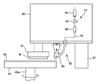
- FIG. 3 is a side view showing the configuration of the substrate polishing unit.
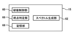
- FIG. 4 is an explanatory diagram showing an example of the configuration of the control device.
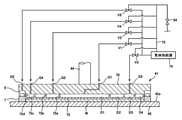
- FIG. 5 is a partial cross-sectional view showing the configuration of the substrate polishing unit.
- FIG. 6 is a side view showing the configuration of the gas supply device.
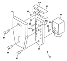
- FIG. 7 is a perspective view showing the configuration of the holding mechanism of the acoustic sensor.
- FIG. 8 is a perspective sectional view showing the configuration of the acoustic sensor.
- FIG. 9A and 9B are explanatory views showing the internal configuration of the acoustic sensor, where FIG. 9A shows a case where it is viewed from the detection surface side, and FIG. 9B shows a case where it is viewed from the side surface.
- FIG. 10 is a side view showing another example of the configuration of the gas supply device.
- FIG. 1 is a plan view showing the overall configuration of the substrate processing apparatus.
- the substrate processing apparatus 10 is divided into a load / unload unit 12, a polishing unit 13, and a cleaning unit 14, which are provided inside the rectangular housing 11. Further, the substrate processing device 10 includes a control device 15 that controls the operation of processing such as substrate transfer, polishing, and cleaning.
- the load / unload unit 12 includes a plurality of front load units 20, a traveling mechanism 21, and a transfer robot 22.
- a substrate cassette for stocking a large number of substrates (wafers) W is placed on the front load portion 20.
- the transfer robot 22 is provided with two hands up and down, and by moving on the traveling mechanism 21, the substrate W in the substrate cassette placed on the front load portion 20 is taken out and sent to the polishing portion 13 and cleaned. The operation of returning the processed board sent from the unit 14 to the board cassette is performed.
- the polishing unit 13 is a region for polishing (flattening) the substrate, and a plurality of polishing units 13A to 13D are provided and arranged along the longitudinal direction of the substrate processing apparatus.
- Each polishing unit has a top ring for polishing while pressing the substrate W on the polishing table against the polishing pad, a liquid supply nozzle for supplying a liquid such as polishing liquid or pure water to the polishing pad, and polishing of the polishing pad. It is equipped with a dresser that sharpens the surface (dressing) and an atomizer that injects a mixed liquid of liquid and gas or a mist-like liquid onto the polished surface to wash away the polishing debris and abrasive grains remaining on the polished surface.
- the first and second linear transporters 16 and 17 are provided between the polishing unit 13 and the cleaning unit 14 as a transport mechanism for transporting the substrate W.
- the first linear transporter 16 is a first position for receiving the substrate W from the load / unload unit 12, a second and third positions for transferring the substrate W to the polishing units 13A and 13B, and a second linear transporter. It is movable to and from the fourth position for passing the substrate W to 17.
- the second linear transporter 17 is located between the fifth position for receiving the substrate W from the first linear transporter 16 and the sixth and seventh positions for transferring the substrate W to the polishing units 13C and 13D. It is said to be movable. Between these transporters 16 and 17, a swing transporter 23 for sending the substrate W from the fourth position or the fifth position to the cleaning unit 14 and from the fourth position to the fifth position is provided.
- the cleaning unit 14 includes a first substrate cleaning device 30, a second substrate cleaning device 31, a substrate drying device 32, and transfer robots 33 and 34 for transferring the substrate between these devices.
- the substrate W that has been polished by the polishing unit is cleaned (primary cleaning) by the first substrate cleaning device 30, and then further cleaned (finish cleaning) by the second substrate cleaning device 31.
- the washed substrate is carried into the substrate drying device 32 from the second substrate cleaning device 31 and subjected to spin drying.
- the dried substrate W is taken out by the transfer robot 22 and returned to the substrate cassette placed on the front load unit 20.
- FIG. 2 is a perspective view schematically showing the configurations of the polishing units 13A to D.
- the polishing unit 40 holds a polishing pad 42 having a polishing surface 42a on the upper surface, a polishing table 43 to which the polishing pad 42 is attached, and a substrate W such as a wafer to be polished, and is brought into sliding contact with the polishing surface 42a. It is provided with a top ring 41 for polishing and a dresser for dressing the polished surface 42a.
- the polishing table 43 is connected to a motor (not shown), and the polishing table 43 and the polishing pad 42 rotate in the directions indicated by the arrows in the figure.
- the top ring 41 is connected to the lower end of the drive shaft 44 protruding downward from the top ring head cover 46 covering the drive mechanism, and the bottom surface thereof constitutes a substrate holding surface for holding the substrate by vacuum suction or the like. Further, the top ring 41 moves between the polishing position located above the polishing table 43 and the substrate delivery position on the side of the polishing table due to the swing of the swivel arm (not shown) accompanying the rotation of the swing shaft 47. It is possible.
- the top ring 41 is configured to hold the substrate W on its lower surface by vacuum suction. Further, the polishing table 43 can be rotated around the table shaft 43a by a motor (not shown). The top ring 41 and the polishing table 43 rotate in the direction indicated by the arrow, and in this state, the top ring 41 presses the substrate W against the polishing surface 42a on the upper side of the polishing pad 42 held by the polishing table 43. In the presence of the polishing liquid supplied from the polishing liquid supply nozzle 45 onto the polishing pad 42, the substrate W is slidably contacted with the polishing pad 42 and polished.
- the substrate W is composed of an upper layer such as a metal or a silicon oxide film and a lower layer which is a silicon film, for example. Since the materials constituting the upper layer and the lower layer of the substrate W are different, when the polishing of the upper layer of the substrate W progresses and the lower layer is exposed, the acoustic spectrum (power spectrum) of the polishing sound by the substrate W and the polishing pad 42 changes.
- the configuration of the substrate W in the present invention is not limited to this, and various materials used in the semiconductor chip manufacturing process can be used.
- an acoustic sensor 50 for detecting a polishing sound from the substrate W is arranged in the vicinity of the top ring 41.
- an ultrasonic microphone see reference numeral 100 in FIG. 8 is used, and an electric signal is detected by detecting a polishing sound caused by friction between the substrate W pressed by the top ring 41 and the polishing pad 42. Output as (acoustic signal).
- the acoustic sensor 50 is connected to the control device 15 (see FIG. 4), and an acoustic signal corresponding to the polishing sound of the substrate W is sent to the control device 15.
- an acoustic emission sensor may be used as the acoustic sensor 50.
- the acoustic sensor 50 is fixed to the bottom of the top ring head cover 46 by the holding mechanism 52. Further, inside the top ring head cover 46, a pipe 53 for supplying an inert gas such as air or nitrogen to the acoustic sensor 50, a solenoid valve 54, a flow rate adjusting valve 55, and a clean filter 56 are provided, and these are provided.
- the gas supply device 57 is configured. The detailed configuration of the holding mechanism 52 and the gas supply device 57 will be described later.
- FIG. 4 shows an example of the configuration of the control device 15.
- the control device 15 is, for example, a general-purpose computer device, and includes a CPU, a memory for storing a control program, an input unit, a display unit, and the like.
- the control device 15 operates as a polishing control unit 60, a spectrum generation unit 62, and an end point determination unit 66 by activating a control program stored in the memory, thereby comprehensively controlling the operation of the polishing unit 40.
- the configuration of the control device 15 is not limited to that shown in FIG. 4, and the configuration for controlling the operation of other elements of the substrate processing device 10 (for example, the load / unload unit 12 and the cleaning unit 14) and the configuration described later. It is also provided with a configuration for controlling the gas supply to the inside of the acoustic sensor 50.
- the control program for controlling the operation of the board processing device 10 may be installed in advance in the computer constituting the control device 15, or may be stored in a storage medium such as a CD-ROM or a DVD-ROM. It may be installed in the control device 15 via the Internet.
- the polishing control unit 60 controls the operation of the top ring 41, the polishing table 43, etc. constituting the polishing unit 40, and performs a polishing process on the substrate W held by the top ring 41.
- the spectrum generation unit 62 performs FFT (Fast Fourier Transform) on the data of the acoustic signal (the signal caused by the friction sound of the substrate W pressed by the polishing pad 42) transmitted from the acoustic sensor 50 to perform the frequency.
- FFT Fast Fourier Transform
- the components and their intensities are extracted and output as a power spectrum (sound pressure level with respect to frequency) of the acoustic signal of the substrate W.
- the end point determination unit 66 monitors the power spectrum in a predetermined frequency band (monitor range), and determines whether or not a predetermined change has occurred in the power spectrum in the monitor range. When the end point determination unit 66 detects a change in the power spectrum in the monitor range, the end point determination unit 66 sends a signal instructing the end of substrate polishing to the polishing control unit 60.
- a predetermined frequency band monitoring range
- the end point determination unit 66 sends a signal instructing the end of substrate polishing to the polishing control unit 60.
- the storage unit 68 is, for example, a non-volatile memory device, and is defined for each of the signal information received from the acoustic sensor 50, the power spectrum information generated by the spectrum generation unit 62, and the type of each layer constituting the substrate W. Information such as the monitor range is stored and read out as appropriate.
- the top ring 41 has a head body 70 fixed to the lower end of the top ring shaft 44, a retainer ring 71 that supports the side edges of the substrate W, and the substrate W on the polished surface of the polishing pad 42. It is provided with a flexible elastic film 72 that presses against it.
- the retainer ring 71 is arranged so as to surround the substrate W, and is connected to the head main body 70.
- the elastic film 72 is attached to the head body 70 so as to cover the lower surface of the head body 70.
- the head body 70 is formed of a material such as a resin such as engineering plastic (for example, PEEK), and the elastic film 72 is excellent in strength and durability of, for example, ethylene propylene rubber (EPDM), polyurethane rubber, silicon rubber and the like. It is made of a material such as rubber.
- the head body 70 and the retainer ring 71 constituting the top ring 41 are configured to rotate integrally by the rotation of the top ring shaft 47.
- the retainer ring 71 is arranged so as to surround the head body 70 and the elastic film 72.
- the retainer ring 71 is a member made of a ring-shaped resin material that comes into contact with the polishing surface 42a of the polishing pad 42, and the polishing pad 42 is held horizontally so that the polishing pad 42 corresponding to the outer periphery of the substrate W is kept horizontal. Hold. Further, the retainer ring 71 is arranged so as to surround the outer peripheral edge of the substrate W held by the head body 70, and supports the outer peripheral edge of the substrate W so that the substrate W being polished does not pop out from the top ring 41. do.
- the upper surface of the retainer ring 71 is connected to an annular retainer ring pressing mechanism (not shown), and a uniform downward load is applied to the entire upper surface of the retainer ring 71. As a result, the lower surface of the retainer ring 71 is pressed against the polishing surface 42a of the polishing pad 42.
- the elastic membrane 72 is provided with a plurality of (four in FIG. 4) annular peripheral walls 72a, 72b, 72c, 72d arranged concentrically. With these plurality of peripheral walls 72a to 72d, a circular first pressure chamber D1 located in the center between the upper surface of the elastic film 72 and the lower surface of the head body 70, and annular second, third, and fourth pressures are used. The chambers D2, D3 and D4 are formed.
- flow paths G1 communicating with the central first pressure chamber D1 and flow paths G2 to G4 communicating with the second to fourth pressure chambers D2 to D4 are formed, respectively.
- These flow paths G1 to G4 are each connected to the gas supply source 74 via a gas line.
- Each gas line is equipped with an air operated valve (one of V1 to V4) and a pressure controller (not shown).
- the air operated valves V1 to V4 are valves that can be switched on and off depending on the magnitude of the air pressure, and can be switched on and off by the control device 15 through the switching line 73 (provided separately from the gas line) from the gas supply source 74. ..
- a gas supply source different from the gas supply source 74 may be provided to control the on / off of the air operating valves V1 to V4.
- a retainer pressure chamber D5 is formed directly above the retainer ring 71, and the retainer pressure chamber D5 is a gas line in which a flow path G5 formed in the head body 70, an air operating valve V5, and a pressure controller (not shown) are installed. It is connected to the gas supply source 74 via.
- the pressure controller installed in each gas line has a pressure adjusting function for adjusting the pressure of the pressure gas supplied from the gas supply source 74 to the pressure chambers D1 to D4 and the retainer pressure chamber D5, respectively.
- the operation of the pressure controller and the air operated valves V1 to V5 is controlled by the control device 15.
- the gas supply source 74 is connected to the solenoid valve 54 of the gas supply mechanism 57 through the switching line 73, and the solenoid valve 54 is operated by the control device 15.
- the acoustic sensor 50 is fixed to the bottom of the top ring head cover 46 by the holding mechanism 52.
- the holding mechanism 52 includes a cover mounting member 83, a support plate 84, and a bracket 85.
- the acoustic sensor 50 is connected to the joint 94 via a tube 93 that accommodates the air pipe 53 and the wiring 92 from the acoustic sensor 50.
- the joint 94 enters the inside of the support portion 95 attached to the bottom portion 46a of the top ring head cover 46, whereby the joint 94 is fixed to the bottom portion of the top ring head cover 46.
- the other end of the support portion 95 provided on the top ring head cover 46 is sealed by a sealing member 96, which prevents the inside of the top ring head cover 46 from being exposed to the outside air.
- the joint 94 and the sealing member 96 are formed with through holes for passing the wiring 92 from the acoustic sensor 50, whereby the acoustic sensor 50 is electrically connected to the control device 15.
- the sealing member 96 shields the inside of the top ring head cover 46 and the acoustic sensor 50 from each other, thereby preventing the gas supplied to the acoustic sensor 50 from flowing back into the top ring head cover 46 and supplying the gas. Gas is efficiently supplied to the sensor body (ultrasonic microphone).
- sealing member 96 for example, a rubber stopper as an elastic body is preferably used, but there is no particular limitation as long as it is a member capable of sealing gas. , Caulking material may be used.
- the gas supply device 57 is provided to supply a gas for removing water droplets that may adhere to the inside of the acoustic sensor 50, and is composed of a solenoid valve 54, a flow rate adjusting valve 55, and a clean filter 56, which are top ring head covers. It is fixed inside the 46.
- the solenoid valve 54 is connected to the gas supply source 74 and is operated by the control device 15 to turn on / off the supply of gas (for example, nitrogen gas) to the acoustic sensor 50.
- the flow rate adjusting valve 55 is, for example, a speed controller with a dial, and adjusts the amount of gas supplied to the acoustic sensor 50 by turning the dial when the device is stopped (for example, during maintenance). Alternatively, the flow rate adjusting valve 55 may be configured to automatically adjust the supply amount.
- the clean filter 56 removes impurities such as particles contained in the gas supplied from the gas supply source 74, and prevents foreign matter from entering the inside of the acoustic sensor 50. Further, the holder 94 and the sealing member 96 are formed with through holes for passing the gas pipe 53 from the acoustic sensor 50.
- the gas supply device 57 that supplies gas to the acoustic sensor 50 inside the top ring head cover 46 it is possible to configure the gas supply device to the acoustic sensor at low space and low cost.
- the cover mounting member 83 is fixed to the bottom portion 46a of the top ring head cover 46, and a plurality of positioning holes 83a are formed at regular intervals.
- the support plate 84 has a plurality of positioning holes formed at regular intervals on the surface (rear surface in FIG. 7) in contact with the cover mounting member 83, and the positioning pins 86 are the positioning holes of the cover mounting member 83 and the support plate 84.
- the bracket 85 has a plurality of positioning holes 85a formed at regular intervals on a surface (front surface in FIG. 7) in contact with the support plate 84. Similarly, a plurality of positioning holes are formed at regular intervals on the corresponding surface (back surface in FIG. 7) of the support plate 84.
- a plurality of positioning holes 50a are formed concentrically at regular intervals on a surface in contact with the bracket 85 (front surface in FIG. 7), which is a corresponding surface of the bracket 85 (rear surface in FIG. 7). ) Corresponds to a plurality of positioning holes formed concentrically at regular intervals. Then, the mounting angle of the acoustic sensor 50 can be adjusted by inserting the positioning pin 90 into the positioning hole of the acoustic sensor 50 and the bracket 85. Further, the acoustic sensor 50 is fixed to the bracket 85 by the bolt 91.
- the acoustic sensor 50 includes a sensor body 100 for detecting a polishing sound from the substrate W and a sensor cover 101, and the sensor body 100 has entered the inside of the sensor cover 101. It is held in a state.
- a waterproof sheet 104 is arranged on the front surface of the detection surface 100a of the sensor body 100, and is further sandwiched between the sensor cover 101 and the front cover 106 by the front cover 106 having an opening 106a provided on the front surface thereof. It is fixed in the state of being fixed.
- the waterproof sheet 104 is, for example, a fluororesin sheet having a large number of minute openings formed therein, and can block the intrusion of water droplets into the inside of the acoustic sensor 50 without blocking the polishing sound from the substrate W. ..
- the wiring 92 is connected to the surface of the sensor body 100 opposite to the detection surface via a connector. Further, a joint 108 accommodating a part of the wiring 92 is inserted in the opening formed in the sensor cover 101, and the wiring 92 is protected from the outside air by the joint 108 and the tube 93.
- the waterproof sheet 104 arranged on the detection surface side of the acoustic sensor 50 can prevent the intrusion of water droplets, it cannot completely prevent the intrusion of water vapor finer than the water droplets. Further, since the inside of the polishing unit 40 needs to be kept in a wet state so that the polishing liquid does not dry, water vapor may accumulate inside the acoustic sensor 50 and dew condensation may occur, which causes the acoustic sensor 50. The detection performance of polishing sound deteriorates, or the sensor fails.
- the gas is aerated inside the acoustic sensor 50 to remove water vapor to the outside, and at the same time, the gas vapor is removed to the outside. It is designed to prevent water droplets and water vapor from entering the inside of the acoustic sensor 50 from the outside. This makes it possible to prevent moisture from adhering to the sensor body 100.
- the adhesion of water means that water droplets adhere to the sensor body 100 and water vapor condenses on the surface of the sensor body 100.
- a recess for accommodating the sensor main body 100 and a pair of grooves 102 are formed on both sides thereof.
- the gas from the gas supply source 74 is supplied from the surface opposite to the detection surface of the acoustic sensor 50 through the pipe 53 in the tube 93, the gas flows through the groove 102 of the sensor body 100, and the minute amount of the waterproof sheet 104 is reached. It passes through the opening to the outside of the sensor body 50 (see the arrow in FIG. 9B). As a result, gas can be ventilated inside the acoustic sensor 50.
- the gas is supplied to the inside of the acoustic sensor 50 at the timing after the polishing process to the substrate W is completed or before the polishing process to the substrate W is started. During the polishing process to the substrate W (more specifically, the polishing sound is being detected by the acoustic sensor 50), the gas supply to the inside of the acoustic sensor 50 is stopped, so that the polishing sound of the acoustic sensor 50 is generated by the gas supply. It is possible to eliminate the risk of deterioration in detection performance.
- a flow rate adjusting valve 55 may be provided and connected in parallel to the solenoid valve 111 so that the gas from the flow rate adjusting valve 55 flows through the joint 114 to the clean filter 56. This makes it possible to accurately control the amount of gas supplied to the acoustic sensor 50. Further, even if a problem occurs in one of the flow rate adjusting valves 55, it is possible to pass gas through the inside of the acoustic sensor 50 and perform ventilation by using the other flow rate adjusting valve 55.
- the gas is passed through the inside of the acoustic sensor 50 to ventilate the sound sensor 50 at the timing after the polishing is completed, but the present invention is not limited to this, and the present invention is not limited to this, for example, at regular time intervals. It may be ventilated. Further, it may be configured to be ventilated during the substrate polishing process, but since the detection performance by the acoustic sensor 50 may be deteriorated due to the flow of gas, when the gas is ventilated during the substrate polishing process, the gas is ventilated. It is preferable to reduce the supply amount (or stop the gas supply during the measurement of the polishing sound by the acoustic sensor 50).
- the gas is supplied to the acoustic sensor 50 from the side opposite to the detection surface 100a (the surface on the waterproof sheet 104 side), but the waterproof sheet 104, the sealing member 96, the joint 108, and the tube. Since the internal space where the sensor body is located is semi-sealed by 93, the gas may be supplied from the front side or the side surface of the detection surface 100a.
Landscapes
- Engineering & Computer Science (AREA)
- Mechanical Engineering (AREA)
- Physics & Mathematics (AREA)
- Analytical Chemistry (AREA)
- Plasma & Fusion (AREA)
- Chemical & Material Sciences (AREA)
- Health & Medical Sciences (AREA)
- Epidemiology (AREA)
- Public Health (AREA)
- Acoustics & Sound (AREA)
- Mechanical Treatment Of Semiconductor (AREA)
- Finish Polishing, Edge Sharpening, And Grinding By Specific Grinding Devices (AREA)
- Constituent Portions Of Griding Lathes, Driving, Sensing And Control (AREA)
- Grinding-Machine Dressing And Accessory Apparatuses (AREA)
Abstract
Description
Claims (7)
- 基板を研磨パッドに押し付けることにより前記基板の研磨を行う基板処理装置において、
前記基板を回転可能に保持する基板保持装置と、
前記基板の研磨音を検出して音響信号として出力するセンサ本体と、当該センサ本体を収容するカバー部材を備えた音響センサと、
前記音響信号から前記基板の研磨終点を検出する終点検出部と、
前記センサ本体への水分の付着を防止するために、前記カバー部材の内部へ気体を供給する気体供給装置を備えたことを特徴とする基板処理装置。 - 前記気体供給装置は、気体を供給する気体供給源と、前記気体供給源からの前記音響センサへの気体の供給をオン・オフする切替部と、気体の供給量を調節する調節部と、前記音響センサの内部へ供給される気体から異物を除去するためのフィルタを備えたことを特徴とする、請求項1記載の基板処理装置。
- 前記基板保持装置は、基板を押圧するための複数の圧力室を形成する弾性膜と、前記弾性膜が取り付けられるヘッド本体と、前記基板を囲むように配置されたリテーナリングと、前記気体供給源から気体を供給することで前記複数の圧力室の圧力を制御する圧力制御部とを備えることを特徴とする、請求項2記載の基板処理装置。
- 前記センサ本体の検出面側には、前記カバー部材の内部への水滴の浸入を防止する防水シートが設けられていることを特徴とする、請求項1乃至3のいずれか1項に記載の基板処理装置。
- 前記気体供給装置は前記カバー部材内に気体を供給するように前記カバー部材と接続されており、
前記カバー部材には、前記気体供給装置からの気体を通過させるための溝が形成されており、
前記防水シートには、前記気体供給装置からの気体を通過させるための複数の微小開口が形成されていることを特徴とする、請求項4記載の基板処理装置。 - 前記基板保持装置を支持する支持部材と、前記支持部材に固定され前記音響センサを保持する保持機構を備え、
前記音響センサは、一定間隔で形成された複数の位置決め穴及びピンを介して、取付位置及び前記研磨パッドに対する取付角度が調節可能とされていることを特徴とする、請求項1乃至5のいずれか1項に記載の基板処理装置。 - 基板を研磨パッドに押し付けることにより前記基板の研磨を行う基板処理装置において、前記基板の研磨音を検出して音響信号として出力するセンサ本体への水分の付着を防止するための防水装置であって、
前記センサ本体を収容するカバー部材と、
前記センサ本体への水滴の付着を防止するために、前記カバー部材の内部へ気体を供給する気体供給装置とを備えたことを特徴とする防水装置。
Priority Applications (3)
| Application Number | Priority Date | Filing Date | Title |
|---|---|---|---|
| KR1020237004538A KR20230037602A (ko) | 2020-07-13 | 2021-07-09 | 기판 처리 장치 및 음향 센서용 방수 장치 |
| CN202180060959.2A CN116195035A (zh) | 2020-07-13 | 2021-07-09 | 基板处理装置和声音传感器用防水装置 |
| US18/005,216 US20230268194A1 (en) | 2020-07-13 | 2021-07-09 | Substrate processing apparatus, and waterproofing device for acoustic sensor |
Applications Claiming Priority (2)
| Application Number | Priority Date | Filing Date | Title |
|---|---|---|---|
| JP2020120201A JP7523269B2 (ja) | 2020-07-13 | 2020-07-13 | 基板処理装置及び音響センサ用防水装置 |
| JP2020-120201 | 2020-07-13 |
Publications (1)
| Publication Number | Publication Date |
|---|---|
| WO2022014475A1 true WO2022014475A1 (ja) | 2022-01-20 |
Family
ID=79555467
Family Applications (1)
| Application Number | Title | Priority Date | Filing Date |
|---|---|---|---|
| PCT/JP2021/025877 Ceased WO2022014475A1 (ja) | 2020-07-13 | 2021-07-09 | 基板処理装置及び音響センサ用防水装置 |
Country Status (6)
| Country | Link |
|---|---|
| US (1) | US20230268194A1 (ja) |
| JP (1) | JP7523269B2 (ja) |
| KR (1) | KR20230037602A (ja) |
| CN (1) | CN116195035A (ja) |
| TW (1) | TW202215519A (ja) |
| WO (1) | WO2022014475A1 (ja) |
Families Citing this family (1)
| Publication number | Priority date | Publication date | Assignee | Title |
|---|---|---|---|---|
| US20250062163A1 (en) * | 2023-08-18 | 2025-02-20 | Applied Materials, Inc. | Acoustic monitoring for process reliability during polishing |
Citations (2)
| Publication number | Priority date | Publication date | Assignee | Title |
|---|---|---|---|---|
| WO2010067732A1 (ja) * | 2008-12-12 | 2010-06-17 | 旭硝子株式会社 | 研磨装置、及び研磨方法、並びにガラス板の製造方法 |
| JP2017528904A (ja) * | 2014-06-16 | 2017-09-28 | アプライド マテリアルズ インコーポレイテッドApplied Materials,Incorporated | 一体型センサを有する化学機械研磨保持リング |
Family Cites Families (15)
| Publication number | Priority date | Publication date | Assignee | Title |
|---|---|---|---|---|
| US5222329A (en) * | 1992-03-26 | 1993-06-29 | Micron Technology, Inc. | Acoustical method and system for detecting and controlling chemical-mechanical polishing (CMP) depths into layers of conductors, semiconductors, and dielectric materials |
| US5245794A (en) * | 1992-04-09 | 1993-09-21 | Advanced Micro Devices, Inc. | Audio end point detector for chemical-mechanical polishing and method therefor |
| US5439551A (en) * | 1994-03-02 | 1995-08-08 | Micron Technology, Inc. | Chemical-mechanical polishing techniques and methods of end point detection in chemical-mechanical polishing processes |
| US6071375A (en) * | 1997-12-31 | 2000-06-06 | Lam Research Corporation | Gas purge protection of sensors and windows in a gas phase processing reactor |
| JP3292243B2 (ja) * | 1999-06-30 | 2002-06-17 | 日本電気株式会社 | 研磨終点検出装置 |
| JP2005251887A (ja) * | 2004-03-03 | 2005-09-15 | Matsushita Electric Ind Co Ltd | 洗浄装置及び洗浄方法 |
| US8795032B2 (en) * | 2008-06-04 | 2014-08-05 | Ebara Corporation | Substrate processing apparatus, substrate processing method, substrate holding mechanism, and substrate holding method |
| JP2014172161A (ja) * | 2013-03-13 | 2014-09-22 | Ebara Corp | 基板割れ検知装置およびこれを備えた研磨装置並びに基板割れ検知方法 |
| CN203636514U (zh) * | 2013-11-07 | 2014-06-11 | 吉林大学 | 面向规则金刚石工具头超精密研磨/抛光加工平台 |
| JP6344950B2 (ja) * | 2014-03-31 | 2018-06-20 | 株式会社荏原製作所 | 研磨装置及び研磨方法 |
| JP2016165792A (ja) * | 2015-03-05 | 2016-09-15 | ミクロ技研株式会社 | 研磨ヘッド及び研磨処理装置 |
| KR20180089037A (ko) * | 2017-01-31 | 2018-08-08 | 주식회사 케이씨텍 | 기판 처리 장치 및 그 제어방법 |
| JP6990980B2 (ja) * | 2017-03-31 | 2022-01-12 | 株式会社荏原製作所 | 基板処理装置 |
| JP6437608B1 (ja) * | 2017-09-08 | 2018-12-12 | 東芝メモリ株式会社 | 研磨装置、研磨方法、および研磨制御装置 |
| JP2021144972A (ja) * | 2020-03-10 | 2021-09-24 | キオクシア株式会社 | 半導体製造装置 |
-
2020
- 2020-07-13 JP JP2020120201A patent/JP7523269B2/ja active Active
-
2021
- 2021-07-09 CN CN202180060959.2A patent/CN116195035A/zh active Pending
- 2021-07-09 US US18/005,216 patent/US20230268194A1/en not_active Abandoned
- 2021-07-09 KR KR1020237004538A patent/KR20230037602A/ko not_active Ceased
- 2021-07-09 WO PCT/JP2021/025877 patent/WO2022014475A1/ja not_active Ceased
- 2021-07-09 TW TW110125279A patent/TW202215519A/zh unknown
Patent Citations (2)
| Publication number | Priority date | Publication date | Assignee | Title |
|---|---|---|---|---|
| WO2010067732A1 (ja) * | 2008-12-12 | 2010-06-17 | 旭硝子株式会社 | 研磨装置、及び研磨方法、並びにガラス板の製造方法 |
| JP2017528904A (ja) * | 2014-06-16 | 2017-09-28 | アプライド マテリアルズ インコーポレイテッドApplied Materials,Incorporated | 一体型センサを有する化学機械研磨保持リング |
Also Published As
| Publication number | Publication date |
|---|---|
| TW202215519A (zh) | 2022-04-16 |
| CN116195035A (zh) | 2023-05-30 |
| US20230268194A1 (en) | 2023-08-24 |
| JP7523269B2 (ja) | 2024-07-26 |
| KR20230037602A (ko) | 2023-03-16 |
| JP2022017108A (ja) | 2022-01-25 |
Similar Documents
| Publication | Publication Date | Title |
|---|---|---|
| KR102677387B1 (ko) | 화학적 기계적 연마 동안 진동들의 모니터링 | |
| JP6877480B2 (ja) | 搬送装置、ワーク処理装置、搬送装置の制御方法、プログラムを記憶する記録媒体 | |
| US10183374B2 (en) | Buffing apparatus, and substrate processing apparatus | |
| KR20160040428A (ko) | 기판 처리 장치 및 처리 방법 | |
| TWI721530B (zh) | 擦光處理裝置及其擦光台之支承面之清洗方法 | |
| JP2000323445A (ja) | 基板センサを有するキャリアヘッド | |
| KR20160030855A (ko) | 처리 모듈, 처리 장치 및 처리 방법 | |
| CN113165142B (zh) | 清洗组件及具备清洗组件的基板处理装置 | |
| US10926374B2 (en) | Substrate processing apparatus | |
| CN105164793A (zh) | 对于利用用于化学机械抛光的晶片及晶片边缘/斜角清洁模块的盘/垫清洁的设计 | |
| JP7581443B2 (ja) | 基板を保持するためのトップリングおよび基板処理装置 | |
| CN109807739A (zh) | 化学机械研磨设备 | |
| US10593570B2 (en) | Substrate holding module, substrate processing apparatus, and substrate processing method | |
| JP7523269B2 (ja) | 基板処理装置及び音響センサ用防水装置 | |
| JP6412385B2 (ja) | コンディショニング部、バフ処理モジュール、基板処理装置、及び、ドレスリンス方法 | |
| CN112894612B (zh) | 用于保持基板的顶环及基板处理装置 | |
| JP6353266B2 (ja) | 冷却装置、及び、基板処理装置 | |
| JP3862435B2 (ja) | ポリッシング装置 | |
| US20260076132A1 (en) | Vacuum hole cleaning apparatus, stage including the same, and substrate treatment apparatus including the vacuum hole cleaning apparatus | |
| JP2016119333A (ja) | バフ処理装置、および、基板処理装置 | |
| JP6091976B2 (ja) | 液体供給装置、及び基板処理装置 | |
| JP2017187311A (ja) | リーク検査装置 | |
| JP2025088032A (ja) | トップリング、および、基板研磨装置 | |
| JP2025032560A (ja) | 基板処理装置、及び異常判定方法 | |
| JP2015152324A (ja) | 基板処理装置、および基板のエッジ欠けを検出する方法 |
Legal Events
| Date | Code | Title | Description |
|---|---|---|---|
| 121 | Ep: the epo has been informed by wipo that ep was designated in this application |
Ref document number: 21842286 Country of ref document: EP Kind code of ref document: A1 |
|
| ENP | Entry into the national phase |
Ref document number: 20237004538 Country of ref document: KR Kind code of ref document: A |
|
| NENP | Non-entry into the national phase |
Ref country code: DE |
|
| 122 | Ep: pct application non-entry in european phase |
Ref document number: 21842286 Country of ref document: EP Kind code of ref document: A1 |
|
| WWR | Wipo information: refused in national office |
Ref document number: 1020237004538 Country of ref document: KR |