WO2022014426A1 - 燃料噴射弁 - Google Patents
燃料噴射弁 Download PDFInfo
- Publication number
- WO2022014426A1 WO2022014426A1 PCT/JP2021/025563 JP2021025563W WO2022014426A1 WO 2022014426 A1 WO2022014426 A1 WO 2022014426A1 JP 2021025563 W JP2021025563 W JP 2021025563W WO 2022014426 A1 WO2022014426 A1 WO 2022014426A1
- Authority
- WO
- WIPO (PCT)
- Prior art keywords
- injection hole
- injection
- radius
- fuel
- valve
- Prior art date
- Legal status (The legal status is an assumption and is not a legal conclusion. Google has not performed a legal analysis and makes no representation as to the accuracy of the status listed.)
- Ceased
Links
Images


Classifications
-
- F—MECHANICAL ENGINEERING; LIGHTING; HEATING; WEAPONS; BLASTING
- F02—COMBUSTION ENGINES; HOT-GAS OR COMBUSTION-PRODUCT ENGINE PLANTS
- F02M—SUPPLYING COMBUSTION ENGINES IN GENERAL WITH COMBUSTIBLE MIXTURES OR CONSTITUENTS THEREOF
- F02M61/00—Fuel-injectors not provided for in groups F02M39/00 - F02M57/00 or F02M67/00
- F02M61/16—Details not provided for in, or of interest apart from, the apparatus of groups F02M61/02 - F02M61/14
- F02M61/18—Injection nozzles, e.g. having valve seats; Details of valve member seated ends, not otherwise provided for
- F02M61/1806—Injection nozzles, e.g. having valve seats; Details of valve member seated ends, not otherwise provided for characterised by the arrangement of discharge orifices, e.g. orientation or size
- F02M61/1813—Discharge orifices having different orientations with respect to valve member direction of movement, e.g. orientations being such that fuel jets emerging from discharge orifices collide with each other
-
- F—MECHANICAL ENGINEERING; LIGHTING; HEATING; WEAPONS; BLASTING
- F02—COMBUSTION ENGINES; HOT-GAS OR COMBUSTION-PRODUCT ENGINE PLANTS
- F02M—SUPPLYING COMBUSTION ENGINES IN GENERAL WITH COMBUSTIBLE MIXTURES OR CONSTITUENTS THEREOF
- F02M61/00—Fuel-injectors not provided for in groups F02M39/00 - F02M57/00 or F02M67/00
- F02M61/04—Fuel-injectors not provided for in groups F02M39/00 - F02M57/00 or F02M67/00 having valves, e.g. having a plurality of valves in series
- F02M61/10—Other injectors with elongated valve bodies, i.e. of needle-valve type
-
- F—MECHANICAL ENGINEERING; LIGHTING; HEATING; WEAPONS; BLASTING
- F02—COMBUSTION ENGINES; HOT-GAS OR COMBUSTION-PRODUCT ENGINE PLANTS
- F02M—SUPPLYING COMBUSTION ENGINES IN GENERAL WITH COMBUSTIBLE MIXTURES OR CONSTITUENTS THEREOF
- F02M61/00—Fuel-injectors not provided for in groups F02M39/00 - F02M57/00 or F02M67/00
- F02M61/16—Details not provided for in, or of interest apart from, the apparatus of groups F02M61/02 - F02M61/14
- F02M61/18—Injection nozzles, e.g. having valve seats; Details of valve member seated ends, not otherwise provided for
- F02M61/1806—Injection nozzles, e.g. having valve seats; Details of valve member seated ends, not otherwise provided for characterised by the arrangement of discharge orifices, e.g. orientation or size
- F02M61/1833—Discharge orifices having changing cross sections, e.g. being divergent
-
- F—MECHANICAL ENGINEERING; LIGHTING; HEATING; WEAPONS; BLASTING
- F02—COMBUSTION ENGINES; HOT-GAS OR COMBUSTION-PRODUCT ENGINE PLANTS
- F02M—SUPPLYING COMBUSTION ENGINES IN GENERAL WITH COMBUSTIBLE MIXTURES OR CONSTITUENTS THEREOF
- F02M61/00—Fuel-injectors not provided for in groups F02M39/00 - F02M57/00 or F02M67/00
- F02M61/16—Details not provided for in, or of interest apart from, the apparatus of groups F02M61/02 - F02M61/14
- F02M61/18—Injection nozzles, e.g. having valve seats; Details of valve member seated ends, not otherwise provided for
- F02M61/1806—Injection nozzles, e.g. having valve seats; Details of valve member seated ends, not otherwise provided for characterised by the arrangement of discharge orifices, e.g. orientation or size
- F02M61/184—Discharge orifices having non circular sections
-
- F—MECHANICAL ENGINEERING; LIGHTING; HEATING; WEAPONS; BLASTING
- F02—COMBUSTION ENGINES; HOT-GAS OR COMBUSTION-PRODUCT ENGINE PLANTS
- F02M—SUPPLYING COMBUSTION ENGINES IN GENERAL WITH COMBUSTIBLE MIXTURES OR CONSTITUENTS THEREOF
- F02M61/00—Fuel-injectors not provided for in groups F02M39/00 - F02M57/00 or F02M67/00
- F02M61/16—Details not provided for in, or of interest apart from, the apparatus of groups F02M61/02 - F02M61/14
- F02M61/18—Injection nozzles, e.g. having valve seats; Details of valve member seated ends, not otherwise provided for
- F02M61/1886—Details of valve seats not covered by groups F02M61/1866 - F02M61/188
Definitions
- This disclosure relates to a fuel injection valve.
- Patent Document 1 a technique for improving spraying by devising the shape of the injection hole of the fuel injection valve has been known.
- the deposit on the inner wall of the injection hole is accumulated by flattening the cross-sectional shape of the injection hole so that the area of the portion of the inner wall of the injection hole where fuel does not flow is small. It is suppressing.
- Patent Document 2 describes that by making the injection hole flat, the thinning of the liquid film is promoted, and atomization and low penetration can be achieved.
- the fuel is placed along the inner wall of the flat injection hole to promote the thinning of the liquid film, and the atomization and low penetration are realized.
- the total amount of the wall surface Wet by atomization or low penetration, no consideration is given to the relationship between the adhesion state of the wall surface Wet and the penetration.
- the fuel after adhesion is quickly evaporated to suppress the bright flame by reducing the residual fuel on the wall surface and reduce the penetration. It is thought that it can be done.
- a thin and wide wall surface Wet is required to be adhered. Therefore, it is necessary to improve the dispersibility of the spray and reduce the variation in fuel concentration and particle size.
- the purpose of the present disclosure is to provide a fuel injection valve that realizes highly dispersed and highly homogeneous spraying.
- the fuel injection valve of the present disclosure includes a nozzle, a needle, and a drive unit.
- the nozzle is provided around the valve shaft, and is a nozzle cylinder that forms a fuel passage inside, a nozzle bottom that closes one end of the nozzle cylinder, "the surface of the nozzle bottom on the nozzle cylinder side” and “what is the nozzle cylinder”. It has a plurality of injection holes that connect to the "opposite surface” and inject fuel in the fuel passage, and an annular valve seat formed around the injection holes in the "nozzle cylinder side surface at the bottom of the nozzle”. ..
- the needle is provided inside the nozzle so that it can reciprocate along the valve shaft, and when it comes into contact with the valve seat, it closes the injection hole, and when it separates from the valve seat, it opens the injection hole.
- the drive unit can move the needle in the valve opening direction or the valve closing direction.
- the injection hole is formed on the "inlet opening on the surface of the nozzle bottom on the nozzle cylinder side" and the "surface on the side of the nozzle bottom opposite to the nozzle cylinder", and the area is the area of the inlet opening. Has a larger outlet opening.
- One or more of the plurality of injection holes is a "flat injection hole” in which the outlet opening has a major axis and a minor axis.
- the flat injection hole further includes one or more "specific flat injection holes”.
- the long axis of the specific flat injection hole is orthogonal to the plane parallel to the valve axis, including the injection hole axis connecting the center of the inlet opening and the center of the outlet opening. Further, the specific flat injection hole has a flat surface portion facing the inner wall with a long axis interposed therebetween.
- the radius of curvature of the long axis direction end of the inlet opening is the first radius of curvature
- the radius of curvature of the long axis direction end of the exit opening is the second radius of curvature.
- the ratio of the second radius of curvature to the first radius of curvature is defined as the radius of curvature ratio.
- the radius of curvature ratio is in the range of 40% to 100%, more preferably in the range of 50% to 90%.
- the radius of curvature ratio of the outlet opening to the inlet opening is in the range of 40% to 100%, so that the liquid film in the injection hole forming the spray is homogeneous. Can be. Therefore, highly dispersed and highly homogeneous spray can be realized.
- a plurality of injection holes are arranged symmetrically with respect to a reference plane including a valve axis, and at least a pair of injection holes having a maximum injection hole angle, which is the angle of the injection hole axis with respect to the valve axis, is a specific flat injection. It constitutes a hole.
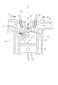
- FIG. 1 is a cross-sectional view showing the overall configuration of the fuel injection valve according to the present embodiment.
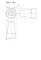
- FIG. 2 is a schematic view of a side-mounted engine on which a fuel injection valve according to the first, sixth to ninth embodiments is mounted.
- FIG. 3 is a view of FIG. 2 from the direction of arrow III.
- FIG. 4 is an enlarged cross-sectional view of the IV portion of FIG. 1 (axial cross-sectional view of the injection hole).
- FIG. 5 is a schematic three-view view showing the shape of the injection hole (tapered injection hole) of the comparative example.
- FIG. 6 is a schematic three-view view showing the shape of the injection hole (flat injection hole) of the present embodiment.
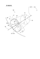
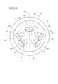
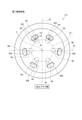
- FIG. 7 is a schematic view showing the injection hole arrangement (5 holes) of the fuel injection valve according to the first embodiment.
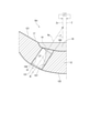
- FIG. 8 is an enlarged view of part VIII of FIG. 7.
- FIG. 9 is an axial cross-sectional view of the injection hole showing the inner wall on the side along which the fuel is in the injection.
- FIG. 10 is a schematic view showing the shape of the injection hole according to the first embodiment.
- FIG. 11 is a diagram illustrating liquid film homogeneity.
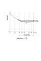
- FIG. 12 is a diagram showing the relationship between the radius of curvature ratio and the liquid film homogeneity.
- FIG. 13 is a schematic view showing the shape of the injection hole according to the second embodiment.
- FIG. 14 is a schematic view showing the shape of the injection hole according to the third embodiment.
- FIG. 15 is a schematic view showing the shape of the injection hole according to the fourth embodiment.
- FIG. 16 is a schematic view showing the shape of the injection hole according to the fifth embodiment.
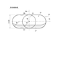
- FIG. 17 is a schematic view showing the injection hole arrangement (5 holes) of the fuel injection valve according to the sixth embodiment.
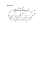
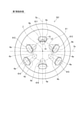
- FIG. 18 is a schematic view showing the injection hole arrangement (6 holes) of the fuel injection valve according to the seventh embodiment.
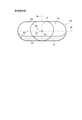
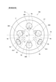
- FIG. 19 is a schematic view showing the injection hole arrangement (6 holes) of the fuel injection valve according to the eighth embodiment.
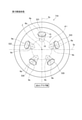
- FIG. 20 is a schematic view showing the injection hole arrangement (6 holes) of the fuel injection valve according to the ninth embodiment.
- FIG. 21 is a schematic diagram of a center-mounted engine equipped with a fuel injection valve according to the tenth and eleventh embodiments.
- FIG. 22 is a schematic view showing the injection hole arrangement (5 holes) of the fuel injection valve according to the tenth embodiment.
- FIG. 23 is a schematic view showing the injection hole arrangement (6 holes) of the fuel injection valve according to the eleventh embodiment.
- the fuel injection valve of the present embodiment is mounted on an engine such as a gasoline engine and injects fuel into the combustion chamber of the engine.
- the side-mounted engine 801 shown in FIGS. 2 and 3 includes a cylinder block 81, a piston 82, a cylinder head 90, an intake valve 95, an exhaust valve 96, and the like.
- a combustion chamber 83 is formed between the inner wall of the cylinder block 81, the wall surface of the cylinder head 90, and the piston 82. The volume of the combustion chamber 83 increases or decreases as the piston 82 reciprocates.
- the cylinder head 90 has an intake manifold 91 and an exhaust manifold 93.
- the intake manifold 91 is formed with an intake passage 92 that guides intake air to the combustion chamber 83.
- the exhaust manifold 93 is formed with an exhaust passage 94 that guides the exhaust generated in the combustion chamber 83 to the atmosphere side.
- the intake valve 95 can be opened and closed between the combustion chamber 83 and the intake passage 92.
- the exhaust valve 96 can be opened and closed between the combustion chamber 83 and the exhaust passage 94.
- the fuel injection valve 70 is provided so as to be inclined toward the cylinder block 81 side of the intake passage 92, that is, the side of the combustion chamber 83. Further, a spark plug 97 is provided between the intake valve 95 and the exhaust valve 96 of the cylinder head 90, that is, at a position corresponding to the center of the combustion chamber 83. The spark plug 97 is provided at a position where the fuel injected from the fuel injection valve 70 does not directly adhere to the spark plug 97, and at a position where the mixture of the fuel and the intake air can be ignited. As described above, the engine 801 is a direct injection type gasoline engine.
- the fuel injection valve 70 is provided so that a plurality of injection holes 13 are exposed on the radial outer portion of the combustion chamber 83. Fuel pressurized by a fuel pump (not shown) is supplied to the fuel injection valve 70. A conical fuel spray Fo is injected into the combustion chamber 83 from the plurality of injection holes 13 of the fuel injection valve 70.
- the engine 801 is provided with two intake valves 95 and an exhaust valve 96, respectively.
- the two intake valves 95 are provided at the two branched ends of the intake manifold 91 on the cylinder block 81 side, respectively.
- the two exhaust valves 96 are provided at the two branched ends of the exhaust manifold 93 on the cylinder block 81 side, respectively.
- the fuel injection valve 70 is mounted so that the valve shaft Z is along the central cross-section Se that includes the shaft of the cylinder block 81 and passes between the two intake valves 95 and between the two exhaust valves 96.
- the fuel injection valve 70 includes a nozzle 10, a housing 20, a needle 30, a movable core 37, a fixed core 41, a coil 45, springs 42, 43 and the like.
- the movable core 37, the fixed core 41 and the coil 45 function as a "driving unit" capable of moving the needle 30 in the valve opening direction or the valve closing direction.
- the nozzle 10 is provided around the valve shaft Z, and has a nozzle cylinder portion 11, a nozzle bottom portion 12, a plurality of injection holes 13, a valve seat 17, and the like.
- the substantially cylindrical nozzle cylinder portion 11 forms a fuel passage 100 inside.
- the nozzle bottom portion 12 closes one end of the nozzle cylinder portion 11.
- the plurality of injection holes 13 formed in the nozzle bottom 12 inject the fuel in the fuel passage 100.
- the valve seat 17 is formed in an annular shape around the injection hole 13 on the surface of the nozzle bottom 12 on the nozzle cylinder 11 side. The injection hole 13 will be described in detail later.
- the housing 20 has a first cylinder member 21, a second cylinder member 22, a third cylinder member 23, an inlet portion 24, and the like.
- the first cylinder member 21, the second cylinder member 22, and the third cylinder member 23 are all substantially cylindrical members, and are coaxial in the order of the first cylinder member 21, the second cylinder member 22, and the third cylinder member 23. They are arranged so that they are connected to each other.
- One end of the inlet portion 24 is connected to the end portion of the third cylinder member 23, and a pipe (not shown) is connected to the other end.
- a filter 25 for collecting foreign matter in the fuel is provided inside the inlet portion 24, a filter 25 for collecting foreign matter in the fuel is provided.
- a fuel passage 100 is formed inside the housing 20.
- the fuel flowing in from the inlet portion 24 passes through the fuel passage 100, passes through the inside of the nozzle cylinder portion 11, and is injected from the injection hole 13.
- the pressure of the fuel in the fuel passage 100 assumed when the fuel injection valve 70 of the present embodiment is used is, for example, about 20 MPa.
- the needle 30 is provided inside the nozzle 10 so as to be reciprocating along the valve shaft Z.
- the needle 30 has a rod-shaped needle body 301, a seat portion 31, a large diameter portion 32, a flange portion 34, and the like.
- the seat portion 31 is formed at the end portion of the needle body 301 on the nozzle 10 side and can come into contact with the valve seat 17.
- the large diameter portion 32 is formed in the vicinity of the seat portion 31 at the end of the needle body 301 on the valve seat 17 side.
- the outer diameter of the large diameter portion 32 is set to be larger than the outer diameter of the end portion of the needle body 301 on the valve seat 17 side.
- the large diameter portion 32 is formed so that the outer wall slides on the inner wall of the nozzle cylinder portion 11 of the nozzle 10.
- the fuel can flow through the notches 33 formed at a plurality of points in the circumferential direction of the outer wall of the large diameter portion 32.
- the flange portion 34 is formed so as to project outward from the end portion of the needle body 301 opposite to the seat portion 31.
- the needle 30 closes the injection hole 13 when the seat portion 31 comes into contact with the valve seat 17, and opens the injection hole 13 when the seat portion 31 separates from the valve seat 17.
- a valve opening direction the direction in which the needle 30 is separated from the valve seat 17
- a valve closing direction the direction in which the needle 30 abuts on the valve seat 17
- the movable core 37 is formed in a substantially cylindrical shape by a magnetic material such as ferritic stainless steel which has been subjected to magnetic stabilization treatment.
- the movable core 37 is provided inside the first cylinder member 21 and the second cylinder member 22 of the housing 20 so as to be relatively movable in the axial direction with respect to the needle body 301.
- the fixed core 41 is formed in a substantially cylindrical shape by a magnetic material such as ferritic stainless steel which has been subjected to magnetic stabilization treatment.
- the fixed core 41 is provided inside the second cylinder member 22 and the third cylinder member 23 of the housing 20 on the inlet portion 24 side with respect to the movable core 37.
- a cylindrical adjusting pipe 54 is press-fitted inside the fixed core 41.
- the spring 42 is, for example, a coil spring, and is provided between the adjusting pipe 54 inside the fixed core 41 and the flange portion 34 of the needle 30.
- the spring 42 together with the needle 30, urges the movable core 37 in the valve closing direction.
- the coil 45 is formed in a substantially cylindrical shape, and is provided so as to surround the radial outside of the second cylinder member 22 and the third cylinder member 23 in the housing 20 in particular. Further, on the radial outer side of the coil 45, a cylindrical holder 26 is provided so as to cover the coil 45.
- the spring 43 is, for example, a coil spring, and urges the movable core 37 toward the fixed core 41, that is, in the valve opening direction.
- the urging force of the spring 43 is smaller than the urging force of the spring 42. Therefore, when the coil 45 is not energized, the seat portion 31 of the needle 30 is pressed against the valve seat 17 by the spring 42, and the needle 30 is closed.
- the fuel flowing in from the inlet portion 24 is guided to the injection hole 13 through the fuel passage 100 between the inside of the fixed core 41 and the adjusting pipe 54, the inner wall of the needle 30 and the housing 20, and the inner wall of the tubular portion 11. Since the periphery of the movable core 37 and the needle 30 is filled with fuel when the fuel injection valve 70 is operated, the movable core 37 and the needle 30 can smoothly reciprocate in the axial direction inside the housing 20. Is.
- FIG. 4 shows an axial cross section of the injection hole 13 corresponding to the expanded cross section of the IV portion of FIG. Note that FIG. 4 omits the illustration of the needle 30.
- the nozzle 10 has a valve seat 17 and a sack wall surface 180 on the "face 121 on the nozzle cylinder 11 side of the nozzle bottom 12" which is the inlet side of the injection hole 13.
- the valve seat 17 is formed in an annular shape around the sack wall surface 180.
- the valve seat 17 is formed in a tapered shape so as to approach the valve shaft Z from the nozzle cylinder portion 11 side toward the sack wall surface 180 side.
- the sack wall surface 180 is recessed from the center of "the surface 121 on the nozzle cylinder 11 side of the nozzle bottom 12" to the side opposite to the nozzle cylinder 11, and forms a sack chamber 18 inside.
- the sack chamber 18 is formed between the sack wall surface 180 and the seat portion 31 of the needle 30.
- the injection hole 13 connects the sack wall surface 180, which is a part of the "face 121 on the nozzle cylinder 11 side of the nozzle bottom 12", and the "surface 122 of the nozzle bottom 12 opposite to the nozzle cylinder 11".
- the fuel in the fuel passage 100 is injected.
- the sack wall surface 180 and "the surface 122 of the nozzle bottom 12 opposite to the nozzle cylinder 11" are formed in a curved surface.
- the injection hole 13 has an inlet opening 14 formed on the sack wall surface 180 which is a surface of the nozzle bottom 12 on the nozzle cylinder 11 side, and an outlet formed on the surface 122 of the nozzle bottom 12 opposite to the nozzle cylinder 11. It has an opening 15. The area of the exit opening 15 is larger than the area of the entrance opening 14.
- injection axis Ho The straight line connecting the center Ci of the inlet opening 14 and the center Co of the outlet opening 15 is defined as "injection axis Ho".
- the injection hole shaft Ho does not always intersect the valve shaft Z. Therefore, assuming a virtual axis Zv that intersects the injection hole axis Ho and is parallel to the valve axis Z, the angle of the injection hole axis Ho with respect to the virtual axis Zv is defined as the “injection angle ⁇ ”.
- the distance between the center Ci of the inlet opening 14 and the center Co of the exit opening 15 as viewed from the VII arrow (that is, the valve axis Z direction) in FIG. 4 is defined as the “center-to-center projection distance P”. If the injection hole length L is substantially constant, the larger the projection distance P between the centers, the larger the injection hole angle ⁇ .
- the entrance opening 14 is a perfect circle, and its diameter is D.
- the ratio (L / D) of the injection hole length L and the inlet opening diameter D is set to 2.0 to 3.0. If (L / D) is smaller than 2.0, the injection direction is not stable. Further, when (L / D) is larger than 3.0, the injection direction speed decreases due to friction with the inner wall of the injection hole, and the atomization performance deteriorates.
- the shape of the injection hole of the fuel injection valve is defined so as to increase the spreading speed of the spray and to make the fuel thinner.
- a jet hole having a shape satisfying the preferable conditions in the present embodiment is defined as a “specific flat jet hole”.
- the "specific flat injection hole” means a "flat injection hole” in which the outlet opening has a major axis and a minor axis, which meets the specific requirements described later.
- the fuel injection valve 70 of the present embodiment at least a part of the plurality of injection holes 13 constitutes a specific flat injection hole, or all the injection holes 13 form a specific flat injection hole. Subsequently, the configuration of the fuel injection valve 70 that achieves the above object will be described in detail for each embodiment.
- each embodiment is defined by a combination of the arrangement of a plurality of injection holes and the shape of each specific flat injection hole.
- the reference numeral of the injection hole is the number of the embodiment in the third digit following "13".
- the reference numeral of the fuel injection valve is the number of the embodiment in the third digit following "70”.
- the "flat injection hole”, which is a superordinate concept of the "specific flat injection hole”, means a flat injection hole whose outlet opening is not a perfect circle but has a major axis and a minor axis.
- the shape of the outlet opening of the flat injection hole includes an elliptical shape, an oval shape, an oval shape, and the like disclosed in Patent Document 2.
- the outlet opening 15 has an oval shape, that is, a track shape, and the injection hole having this shape is referred to as a “track injection hole” in the present specification.
- the antonym of "flat injection hole” is "round injection hole” in which the outlet opening is a perfect circle, or “tapered injection hole” in which the entrance opening and the outlet opening form a coaxial conical shape.
- the three-dimensional shapes of the tapered injection hole 130 as a comparative example and the flat injection hole 131 according to the first embodiment will be described in comparison with each other.
- the inlet opening 14 and the outlet opening 15 have a perfect circular shape and are formed coaxially.
- the spread angle ⁇ of the inner wall of the injection hole 130 in the cross section including the injection hole axis Ho is constant in the circumferential direction.
- FIG. 6 shows a truck injection hole having a track-shaped outlet opening 15 among the flat injection holes.
- the shape of the outlet opening of the flat injection hole includes an elliptical injection hole, an oval injection hole, and the like, in addition to an oval track injection hole.
- the inlet opening 14 of the flat injection hole 131 which is a truck injection hole, is a perfect circle with a radius R1.
- the outlet opening 15 of the flat injection hole 131 has a major axis Ha and a minor axis Hb, and the end points of the arc portions having a radius R2 at both ends in the major axis direction are connected by a parallel straight line portion.
- the inner walls in the short axis direction facing each other spread from the inlet opening 14 toward the exit opening 15 at an angle ⁇ .
- the distance between the inner walls in the long axis direction facing each other is constant.
- the spread angle ⁇ of the inner walls facing each other in the long axis direction is set to 0 °. This is also a specification required from the workability of the injection hole laser.
- the radius R1 of the entrance opening 14 is generalized to the radius of curvature of a curve other than a perfect circle and is referred to as a "first radius of curvature R1".
- the radius R2 of the arc portions at both ends in the major axis direction of the outlet opening 15 is generally referred to as a "second radius of curvature R2".
- each injection hole shaft Ho is biased to one side (lower part of the figure) with respect to the valve shaft Z.
- the reference numeral "511” means the first injection hole of the first pattern of the five-hole specification.
- the reference numeral “634" in FIG. 23 means the No. 4 injection hole of the third pattern of the 6-hole specification.
- "No. 1", “No. 4" and the like are numbers for convenience in this specification.
- FIG. 7 shows the injection hole axis Ho and the major axis Ha for the five specific flat injection holes 511-515, respectively.
- the short axis Hb overlaps the injection hole axis Ho.
- An enlarged view of the No. 4 injection hole 514 is shown in FIG. 8 as a representative view of the specific flat injection hole 131 of the first embodiment.
- the plane including the valve axis Z and represented by the alternate long and short dash line is the reference plane Sy
- the plane including the valve axis Z and represented by the alternate long and short dash line is the reference orthogonal plane Sx.
- the first injection hole 511 is arranged on the reference plane Sym
- the second and third injection holes 512, 513 and 4 and the fifth injection holes 514 and 515 are respectively. It is arranged symmetrically with respect to the reference plane Sy. Nos.
- injection holes 512, 513 and 4, and 5 injection holes 514 and 515 are arranged so that the long axis Ha is separated from the reference plane Sy from the opposite side of the first injection hole 511 toward the first injection hole 511 side. Is located in.
- the aim of this injection hole arrangement is to improve the spray occupancy rate of the target in-cylinder space by utilizing the Coanda effect generated between the sprays from each injection hole 511-515. That is, in the space surrounded by the first, second and third injection holes 511, 512 and 513, a negative pressure is generated in the closed space formed between the three adjacent sprays, and this negative pressure causes spray interference. .. On the other hand, a closed space is not formed between the two sprays even if the sprays interfere with each other. Therefore, in order to avoid spray interference between the three sprays, the Coanda effect between the two sprays is used, and the injection hole arrangement is such that the two sprays interfere more positively than the three sprays.
- each injection hole 511-515 The center of the inlet opening 14 of each injection hole 511-515 is arranged on a concentric circle ⁇ i centered on the valve shaft Z.
- the injection hole angle ⁇ of each injection hole 511-515 correlates with the center-to-center projection distance P (see FIG. 4) as described above. Therefore, the injection hole angle ⁇ of the first injection hole 511 is the smallest, and the injection hole angle ⁇ of the second and third injection holes 512 and 513 is the next smallest. And the injection hole angle ⁇ of the 4th and 5th injection holes 514 and 515 is the maximum.
- the requirements for the "specific flat injection hole” will be described with reference to FIG. 8 by taking the No. 4 injection hole 514 as an example.
- the specific flat injection hole 131 further has three requirements on the premise that it is a flat injection hole having a major axis Ha and a minor axis Hb.
- the long axis Ha of the specific flat injection hole 131 includes the injection hole axis Ho and is orthogonal to the plane Sh parallel to the valve axis.
- the plane Sh is a plane orthogonal to the paper surface of FIGS. 7 and 8.
- the specific flat injection hole 131 has a flat surface portion 157, 158 facing the inner wall with the long axis Ha interposed therebetween.
- the region sandwiched between the two straight lines indicates a flat surface portion.
- a straight line indicating the boundary of the flat surface portion is shown only for a part of the injection holes.
- the liquid film LF is shown on the inner wall on the flat surface portion 157 side across the long axis Ha, and the liquid film LF is not shown on the inner wall on the flat surface portion 158 side across the long axis Ha.
- the liquid film LF is a fuel along the inner wall at the time of injection.
- the valve shaft Z In the injection hole arrangement of FIG. 7, for the first injection hole 511 and the fourth and fifth injection holes 514 and 515 in which the injection hole shaft Ho is inclined toward the outside diameter of the valve shaft Z, the valve shaft Z side.
- the inner wall of is the "inner wall on the side where the fuel runs along at the time of injection".
- the inner wall on the reference plane Sy side becomes the "inner wall on the side along which the fuel is injecting". ..
- the third requirement for the specific flat injection hole is that the radius of curvature ratio ⁇ is in the range of 40% to 100%. In terms of language, "40% to 100%” is interpreted as “40% or more and 100% or less”.
- the radius of curvature ratio ⁇ of the specific flat injection hole 131 shown in FIGS. 7 and 8 corresponds to 100%.
- the second radius of curvature R2 used for calculating the radius of curvature ratio ⁇ is, by definition, the curvature of the end portion in the major axis direction of the outlet opening 15 in the "inner wall on the side along which the fuel is injecting with respect to the major axis Ha". Refers to the radius.
- R2 since the radius of curvature on both sides with respect to the long axis Ha is R2, there is no difference regardless of which side of the radius of curvature is used.
- FIG. 9 shows a state in which the liquid film LF of the fuel is along the inner wall of the injection hole 13 at the time of injection in the axial cross section of the injection hole axis Ho shown in FIG.
- the depth direction of the paper surface corresponds to the long axis direction.
- the fuel runs along the inner wall on the side closer to the valve shaft Z, and the fuel does not run along the inner wall on the side far from the valve shaft Z.
- the code of the flat surface portion of the inner wall on the side along which the fuel runs along the long axis is referred to as “157”, and the sign of the flat surface portion of the inner wall on the side along which the fuel does not follow is referred to as “158”.
- the side where the fuel does not follow at the time of injection is described as "the side opposite to the side where the fuel runs at the time of injection” from the viewpoint of ensuring clarity.
- FIG. 10 is an arrow view in the X direction of FIG. 9, that is, a projection view in the direction of the injection hole axis Ho.
- the cross section orthogonal to the injection hole axis Ho shown by the broken line in FIG. 9 is represented as the inlet opening 14 and the outlet opening 15 in FIG.
- the entrance opening 14 is a perfect circle, and its radius is the first radius of curvature R1.
- the outlet opening 15 is formed in a semicircular shape at the end in the major axis direction, and its radius is the second radius of curvature R2.
- the shape of the inner wall on the side along which the fuel runs along the long axis Ha at the time of injection is symmetrical with the shape of the inner wall on the side opposite to the side along which the fuel runs (that is, the flat surface portion 158 side). Is.
- FIG. 11 schematically shows a state in which the thickness of the liquid film LF along the inner wall of the specific flat injection hole 131 varies depending on the position in the major axis direction.
- the average liquid film thickness be Love
- the difference of the liquid film thickness from the average liquid film thickness Love at each position be ⁇ L.
- the value ( ⁇ / Love) obtained by dividing the standard deviation ⁇ of the liquid film thickness by the average liquid film thickness Love is defined as “liquid film homogeneity”.
- the smaller the liquid film homogeneity value the higher the dispersibility of the spray and the lower the wall surface Wet.
- FIG. 12 shows the analysis results on the relationship between the radius of curvature ratio ⁇ of the flat injection hole and the liquid film homogeneity.
- the value of liquid film homogeneity decreases as the radius of curvature ratio ⁇ increases.
- the value of liquid film homogeneity increases as the radius of curvature ratio ⁇ increases. That is, when the radius of curvature ratio ⁇ is about 70%, the value of liquid film homogeneity becomes the minimum.
- the value of the liquid film homogeneity becomes the target value tgt1 or less when the radius of curvature ratio ⁇ is 40% or more and 100% or less.
- the radius of curvature ratio ⁇ is in the range of 40% to 100% as the third requirement of the specific flat injection hole.
- the target value tgt2 of the liquid film homogeneity is set like a two-dot chain line
- the value of the liquid film homogeneity becomes the target value tgt2 or less when the radius of curvature ratio ⁇ is 50% or more and 90% or less. Therefore, in order to achieve better liquid film homogeneity, it is preferable that the radius of curvature ratio ⁇ of the specific flat injection hole is in the range of 50% to 90%.
- R1> R2 it is preferable to adopt the configurations of the second to fifth embodiments described below.
- the entrance opening 14 is a perfect circle, and its radius is the first radius of curvature R1.
- the radius of curvature of the end portion in the major axis direction of the outlet opening 15 on the inner wall on the side along which the fuel is injected with respect to the major axis Ha is the second.
- the second radius of curvature R2 at the end in the major axis direction of the outlet opening 15 is the inlet opening 14 in the inner walls on both sides with respect to the major axis Ha. It is set smaller than the first radius of curvature R1. That is, the relationship of "R2 ⁇ R1" is established.
- a straight portion 159 showing a linear shape is formed on the inner wall of the outlet opening 15 in the minor axis direction. That is, the outlet opening 15 is formed in a substantially rectangular shape in which the square is an arc shape having a second radius of curvature R2.
- the relationship of "R2 ⁇ R1" can be realized with a simple shape according to the target value of the radius of curvature ratio ⁇ .
- the specific flat injection hole 133 of the third embodiment shown in FIG. 14 is the second end portion in the major axis direction of the outlet opening 15 on the inner wall on the side along which the fuel is injected with respect to the major axis Ha (that is, the flat surface portion 157 side).
- the two radius of curvature R2 is set smaller than the first radius of curvature R1 of the inlet opening 14.
- the third radius of curvature R3, which is the radius of curvature of the end in the long axis direction of the outlet opening 15, is the inlet. It is set to be larger than the first radius of curvature R1 of the opening 14. That is, the relationship of "R2 ⁇ R1 ⁇ R3" is established.
- the length of the minor axis Hb (2 ⁇ R2) is the diameter (2 ⁇ ) of the inlet opening 14 with respect to the specific flat injection hole 131 of the first embodiment. It is set smaller than R1). That is, the relationship of "R2 ⁇ R1" is established.
- the positions of the inner walls of the inlet opening 14 and the outlet opening 15 with respect to the injection hole axis Ho are the same.
- the inlet opening 14 is not a perfect circle with respect to the specific flat injection hole 131 of the first embodiment.
- the first radius of curvature R1 of the inlet opening 14 is set larger than the second radius of curvature R2 of the long axis direction end of the outlet opening 15. Has been done.
- the fourth radius of curvature R4 of the inlet opening 14 is the second of the long axis direction end portion of the outlet opening 15. It is set smaller than the radius of curvature R2. That is, the relationship of "R4 ⁇ R2 ⁇ R1" is established.
- the entrance opening 14 does not have to be a perfect circle.
- the product processed in the shape of the specific flat injection hole 131 of the first embodiment is additionally machined in the shape of the specific flat injection hole 135 of the fifth embodiment to modify the product in the direction of reducing the radius of curvature ratio ⁇ . Can be done.
- the sixth to eleventh embodiments are specifications to be mounted on the side-mounted engine 801 shown in FIGS. 2 and 3 as in the first embodiment.
- the tenth and eleventh embodiments are specifications to be mounted on the center-mounted engine 802 shown in FIG.
- Each injection hole arrangement of the sixth to eleventh embodiments is shown by a projection view in the valve axis Z direction corresponding to FIG. 7 of the first embodiment.
- the center of the inlet opening 14 is arranged on a concentric circle ⁇ i centered on the valve shaft Z. Further, as described above, the farther the center of the inlet opening 14 and the center of the outlet opening 15 are in the projection in the valve axis Z direction, the larger the injection hole angle ⁇ referred to in FIGS. 4 and 10. means.
- all the injection holes constitute a specific flat injection hole. That is, the long axis Ha includes the injection hole axis Ho and is orthogonal to the flat surface Sh parallel to the valve axis, and has a flat surface portion on the inner wall facing the long axis Ha with the long axis Ha interposed therebetween. As shown in FIG. 8, since the plane Sh is represented by the same line as the injection hole axis Ho, the description of “Sh” in the figure is omitted.
- the radius of curvature ratio ⁇ is in the range of 40% to 100%.
- some of the injection holes form a specific flat injection hole.
- the fuel injection valve 706 of the sixth embodiment shown in FIG. 17 has five specific flat injection holes 521-525 arranged around the valve shaft Z, similarly to the fuel injection valve 701 of the first embodiment.
- the diameter of the inlet opening 14 is relatively large.
- the ratio of the length of the major axis Ha to the length of the minor axis Hb is larger than that of the 1st injection hole 521. That is, the 2-5th injection hole 522-525 is formed as a flat injection hole having a larger degree of flatness.
- the injection hole angle ⁇ of the second and third injection holes 522 and 523 is the maximum.
- the fuel injection valve 707 of the seventh embodiment shown in FIG. 18 six specific flat injection holes 611-616 are arranged around the valve shaft Z.
- the 1st injection hole 611 and the 6th injection hole 616 are arranged on the reference plane Sy, and the 2nd and 3rd injection holes 612, 613 and 4 and the 5th injection holes 614 and 615 are relative to the reference plane Sy, respectively. They are arranged symmetrically.
- the 2nd and 3rd injection holes 612, 613 and 4 and the 5th injection holes 614 and 615 are arranged so that the long axis Ha is separated from the reference plane Sy from the 6th injection hole 616 side to the 1st injection hole 611 side. Has been done.
- the injection hole angle ⁇ of the first injection hole 611 is the smallest, and the injection hole angles ⁇ of the second and third injection holes 612, 613 and the sixth injection hole 616 are the next smallest.
- the injection hole angles ⁇ of the 4th and 5th injection holes 614 and 615 are the maximum.
- the fuel injection valve 708 of the eighth embodiment shown in FIG. 19 corresponds to a modification relating to the injection hole arrangement of the fuel injection valve 707 of the seventh embodiment, and only the arrangement of the first injection hole 621 is different from the fuel injection valve 707. .. That is, in the first injection hole 621, the injection hole shaft Ho is tilted from the inlet opening 14 toward the outlet opening 15 toward the valve shaft Z, that is, inward with respect to the valve shaft Z. In this configuration, with respect to the first injection hole 621, contrary to the other injection holes 612-616, the inner wall on the opposite side of the valve shaft Z, that is, the inner wall radially outer with respect to the valve shaft Z, "fuel is along with the fuel during injection". It becomes the inner wall on the side.
- the "inner wall on the side along which the fuel runs at the time of injection” is not always the inner wall on the valve shaft Z side.
- the inner wall on the inlet opening 14 side when viewed from the outlet opening 15 in the projection in the valve axis Z direction is the “inner wall on the side along which the fuel is in the injection”. Even with this configuration, high dispersion and high homogeneity spraying can be realized.
- the fuel injection valve 709 of the ninth embodiment shown in FIG. 20 corresponds to another modification regarding the arrangement of the injection holes of the fuel injection valve 707 of the seventh embodiment.
- the fuel injection valve 709 only the 4th and 5th injection holes 614 and 615 are specific flat injection holes common to the fuel injection valve 707, and the other 4 injection holes 601, 602, 603 and 606 are perfect circular injection holes.
- the 4th and 5th injection holes 614 and 615 correspond to "a pair of injection holes having the maximum injection hole angle ⁇ " among the 6 injection holes, and are highly dispersed and high by adopting the shape of the specific flat injection holes. It is considered that the effect of achieving uniform spraying is the greatest.
- the other injection holes are a perfect circle injection hole or a specific flat injection hole. It may be a flat injection hole that is not.
- at least "a pair of injection holes having the maximum injection hole angle ⁇ " constitutes the specific flat injection hole among the plurality of injection holes arranged symmetrically with respect to the reference plane Sy. ..
- at least the 4th and 5th injection holes 514 and 515 form the specific flat injection hole.
- the fuel injection valves of the tenth and eleventh embodiments are mounted in the center of the cylinder head in the center-mounted engine 802 shown in FIG. 21, and a plurality of conical fuel spray Fos are injected into the combustion chamber 83.
- the center-mounted engine is disclosed, for example, in FIG. 11 of JP-A-2018-31275.
- five specific flat injection holes 531-535 are arranged substantially radially around the valve shaft Z.
- the first injection hole 531 is arranged on the side opposite to the spark plug 97 on the reference plane Sy, and the other four injection holes 532-535 are arranged symmetrically with respect to the reference plane Sy.
- the injection hole shaft Ho is tilted toward the outside diameter of the valve shaft Z, and the inner wall on the valve shaft Z side becomes the "inner wall on the side along which the fuel is in the injection".
- each of the injection holes 631-636 is not evenly radial, and the third and fourth injection holes 633 and 634 are arranged unevenly on the spark plug 97 side with respect to the reference orthogonal plane Sx.
- the injection hole shaft Ho is inclined substantially toward the outer diameter of the valve shaft Z, and the inner wall on the valve shaft Z side becomes the "inner wall on the side along which the fuel is in the injection".
- a recess as shown in FIG. 22 of Patent Document 2 may be formed around the opening of the injection hole 13.
- the opening formed on the bottom surface of the recess is regarded as the outlet opening 15, and the axis passing through the center of the outlet opening 15 is defined as the injection hole axis Ho.
- each member in the fuel injection valve is not limited to that shown in FIG. 1, and may be changed so that the same function can be obtained.
- adjacent members of the same material may be formed separately or integrally.
- the fuel injection valve of the present disclosure is not limited to a direct injection type gasoline engine, but may be applied to a diesel engine, a port injection type gasoline engine, or the like.
Landscapes
- Engineering & Computer Science (AREA)
- Chemical & Material Sciences (AREA)
- Combustion & Propulsion (AREA)
- Mechanical Engineering (AREA)
- General Engineering & Computer Science (AREA)
- Fuel-Injection Apparatus (AREA)
Priority Applications (3)
| Application Number | Priority Date | Filing Date | Title |
|---|---|---|---|
| DE112021003797.8T DE112021003797T5 (de) | 2020-07-14 | 2021-07-07 | Kraftstoffeinspritzventil |
| CN202180049366.6A CN115803516B (zh) | 2020-07-14 | 2021-07-07 | 燃料喷射阀 |
| US18/083,816 US12535044B2 (en) | 2020-07-14 | 2022-12-19 | Fuel injection valve |
Applications Claiming Priority (2)
| Application Number | Priority Date | Filing Date | Title |
|---|---|---|---|
| JP2020120814A JP7419997B2 (ja) | 2020-07-14 | 2020-07-14 | 燃料噴射弁 |
| JP2020-120814 | 2020-07-14 |
Related Child Applications (1)
| Application Number | Title | Priority Date | Filing Date |
|---|---|---|---|
| US18/083,816 Continuation US12535044B2 (en) | 2020-07-14 | 2022-12-19 | Fuel injection valve |
Publications (1)
| Publication Number | Publication Date |
|---|---|
| WO2022014426A1 true WO2022014426A1 (ja) | 2022-01-20 |
Family
ID=79554791
Family Applications (1)
| Application Number | Title | Priority Date | Filing Date |
|---|---|---|---|
| PCT/JP2021/025563 Ceased WO2022014426A1 (ja) | 2020-07-14 | 2021-07-07 | 燃料噴射弁 |
Country Status (5)
| Country | Link |
|---|---|
| US (1) | US12535044B2 (enExample) |
| JP (1) | JP7419997B2 (enExample) |
| CN (1) | CN115803516B (enExample) |
| DE (1) | DE112021003797T5 (enExample) |
| WO (1) | WO2022014426A1 (enExample) |
Families Citing this family (2)
| Publication number | Priority date | Publication date | Assignee | Title |
|---|---|---|---|---|
| JP7419997B2 (ja) * | 2020-07-14 | 2024-01-23 | 株式会社デンソー | 燃料噴射弁 |
| DK181672B1 (en) * | 2023-05-12 | 2024-09-17 | Man Energy Solutions Filial Af Man Energy Solutions Se Tyskland | A fuel valve for a large turbocharged two-stroke uniflow crosshead internal combustion engine |
Citations (4)
| Publication number | Priority date | Publication date | Assignee | Title |
|---|---|---|---|---|
| JPH11343947A (ja) * | 1998-05-28 | 1999-12-14 | Toyota Motor Corp | 内燃機関用燃料噴射弁 |
| JP2004332543A (ja) * | 2003-04-30 | 2004-11-25 | Denso Corp | 燃料噴射弁 |
| JP2017002876A (ja) * | 2015-06-15 | 2017-01-05 | 株式会社日本自動車部品総合研究所 | 燃料噴射弁 |
| JP2020008013A (ja) * | 2018-07-12 | 2020-01-16 | 株式会社Soken | 燃料噴射弁 |
Family Cites Families (22)
| Publication number | Priority date | Publication date | Assignee | Title |
|---|---|---|---|---|
| JPS5987271A (ja) * | 1982-11-09 | 1984-05-19 | Yanmar Diesel Engine Co Ltd | デイ−ゼル機関用燃料噴射弁 |
| JP4174814B2 (ja) | 2000-12-04 | 2008-11-05 | 株式会社デンソー | 燃料噴霧シミュレーション装置および燃料噴霧シミュレーション方法 |
| DE102004005526B4 (de) * | 2003-02-05 | 2022-03-31 | Denso Corporation | Kraftstoffeinspritzvorrichtung einer Brennkraftmaschine mit innerer Verbrennung |
| JP5195890B2 (ja) * | 2010-12-21 | 2013-05-15 | トヨタ自動車株式会社 | 燃料噴射弁および内燃機関 |
| JP5668984B2 (ja) * | 2011-05-31 | 2015-02-12 | 株式会社デンソー | 燃料噴射装置 |
| JP6186130B2 (ja) * | 2013-02-04 | 2017-08-23 | 日立オートモティブシステムズ株式会社 | 燃料噴射弁及び燃料噴射弁の製造方法 |
| JP2015200214A (ja) * | 2014-04-07 | 2015-11-12 | 株式会社デンソー | 燃料噴射弁 |
| JP6364962B2 (ja) * | 2014-05-28 | 2018-08-01 | 株式会社デンソー | 燃料噴射弁 |
| JP6380123B2 (ja) * | 2015-01-22 | 2018-08-29 | 株式会社デンソー | 燃料噴射ノズル |
| JP6292188B2 (ja) * | 2015-04-09 | 2018-03-14 | 株式会社デンソー | 燃料噴射装置 |
| JP6365450B2 (ja) * | 2015-07-24 | 2018-08-01 | 株式会社デンソー | 燃料噴射装置 |
| JP2017141681A (ja) * | 2016-02-08 | 2017-08-17 | 株式会社Soken | 燃料噴射ノズル |
| JP6463286B2 (ja) * | 2016-02-15 | 2019-01-30 | 株式会社Soken | 燃料噴射弁 |
| JP6451663B2 (ja) * | 2016-02-24 | 2019-01-16 | 株式会社デンソー | 燃料噴射装置 |
| CN107178449B (zh) * | 2016-03-10 | 2019-11-08 | 株式会社京浜 | 缸内喷射用电磁式燃料喷射阀 |
| JP2018031275A (ja) | 2016-08-23 | 2018-03-01 | 株式会社デンソー | 燃料噴射弁 |
| DE102016222239A1 (de) * | 2016-11-14 | 2018-05-17 | Robert Bosch Gmbh | Injektor zum Einspritzen eines Fluids mit verbessertem Spraybild |
| JP2018204574A (ja) * | 2017-06-07 | 2018-12-27 | 株式会社Soken | 燃料噴射弁 |
| JP7206601B2 (ja) * | 2018-03-08 | 2023-01-18 | 株式会社デンソー | 燃料噴射弁および燃料噴射システム |
| JP2020120814A (ja) | 2019-01-29 | 2020-08-13 | 株式会社ソフイア | 遊技機 |
| JP7272645B2 (ja) * | 2019-06-20 | 2023-05-12 | 株式会社デンソー | 燃料噴射弁 |
| JP7419997B2 (ja) * | 2020-07-14 | 2024-01-23 | 株式会社デンソー | 燃料噴射弁 |
-
2020
- 2020-07-14 JP JP2020120814A patent/JP7419997B2/ja active Active
-
2021
- 2021-07-07 DE DE112021003797.8T patent/DE112021003797T5/de active Pending
- 2021-07-07 WO PCT/JP2021/025563 patent/WO2022014426A1/ja not_active Ceased
- 2021-07-07 CN CN202180049366.6A patent/CN115803516B/zh active Active
-
2022
- 2022-12-19 US US18/083,816 patent/US12535044B2/en active Active
Patent Citations (4)
| Publication number | Priority date | Publication date | Assignee | Title |
|---|---|---|---|---|
| JPH11343947A (ja) * | 1998-05-28 | 1999-12-14 | Toyota Motor Corp | 内燃機関用燃料噴射弁 |
| JP2004332543A (ja) * | 2003-04-30 | 2004-11-25 | Denso Corp | 燃料噴射弁 |
| JP2017002876A (ja) * | 2015-06-15 | 2017-01-05 | 株式会社日本自動車部品総合研究所 | 燃料噴射弁 |
| JP2020008013A (ja) * | 2018-07-12 | 2020-01-16 | 株式会社Soken | 燃料噴射弁 |
Also Published As
| Publication number | Publication date |
|---|---|
| JP7419997B2 (ja) | 2024-01-23 |
| CN115803516B (zh) | 2026-04-21 |
| US12535044B2 (en) | 2026-01-27 |
| DE112021003797T5 (de) | 2023-05-17 |
| JP2022017944A (ja) | 2022-01-26 |
| US20230124555A1 (en) | 2023-04-20 |
| CN115803516A (zh) | 2023-03-14 |
Similar Documents
| Publication | Publication Date | Title |
|---|---|---|
| US10890152B2 (en) | Fuel injection device | |
| US20030234005A1 (en) | Fuel injection valve | |
| CN107407245B (zh) | 燃料喷射装置 | |
| JPWO2014024292A1 (ja) | 燃料噴射弁 | |
| WO2022014426A1 (ja) | 燃料噴射弁 | |
| US8919674B2 (en) | Fuel injection valve | |
| US20120325938A1 (en) | Fuel injection valve | |
| US12055119B2 (en) | Fuel injection valve | |
| CN104564474B (zh) | 燃料喷射阀 | |
| PH12015502333B1 (en) | Fuel injection valve | |
| EP1857669B1 (en) | Fuel injection valve | |
| WO2021075041A1 (ja) | 燃料噴射弁 | |
| KR101711316B1 (ko) | 연료 분사 밸브 | |
| WO2017145639A1 (ja) | 燃料噴射装置 | |
| WO2021250836A1 (ja) | 燃料噴射弁 | |
| JP4138778B2 (ja) | 燃料噴射弁 | |
| JP5478671B2 (ja) | 流体噴射弁による噴霧生成方法、流体噴射弁及び噴霧生成装置 | |
| CN113260783B (zh) | 燃料喷射装置 | |
| WO2016163086A1 (ja) | 燃料噴射装置 | |
| JP2024033960A (ja) | 噴射弁 | |
| JP2021167586A (ja) | 燃料噴射弁 | |
| CN110546375A (zh) | 燃料喷射阀 |
Legal Events
| Date | Code | Title | Description |
|---|---|---|---|
| 121 | Ep: the epo has been informed by wipo that ep was designated in this application |
Ref document number: 21842730 Country of ref document: EP Kind code of ref document: A1 |
|
| 122 | Ep: pct application non-entry in european phase |
Ref document number: 21842730 Country of ref document: EP Kind code of ref document: A1 |