WO2022014187A1 - 水田作業機 - Google Patents
水田作業機 Download PDFInfo
- Publication number
- WO2022014187A1 WO2022014187A1 PCT/JP2021/021168 JP2021021168W WO2022014187A1 WO 2022014187 A1 WO2022014187 A1 WO 2022014187A1 JP 2021021168 W JP2021021168 W JP 2021021168W WO 2022014187 A1 WO2022014187 A1 WO 2022014187A1
- Authority
- WO
- WIPO (PCT)
- Prior art keywords
- rotating body
- central
- seedling planting
- body portion
- frame
- Prior art date
- Legal status (The legal status is an assumption and is not a legal conclusion. Google has not performed a legal analysis and makes no representation as to the accuracy of the status listed.)
- Ceased
Links
Images





Classifications
-
- A—HUMAN NECESSITIES
- A01—AGRICULTURE; FORESTRY; ANIMAL HUSBANDRY; HUNTING; TRAPPING; FISHING
- A01C—PLANTING; SOWING; FERTILISING
- A01C11/00—Transplanting machines
- A01C11/02—Transplanting machines for seedlings
-
- Y—GENERAL TAGGING OF NEW TECHNOLOGICAL DEVELOPMENTS; GENERAL TAGGING OF CROSS-SECTIONAL TECHNOLOGIES SPANNING OVER SEVERAL SECTIONS OF THE IPC; TECHNICAL SUBJECTS COVERED BY FORMER USPC CROSS-REFERENCE ART COLLECTIONS [XRACs] AND DIGESTS
- Y02—TECHNOLOGIES OR APPLICATIONS FOR MITIGATION OR ADAPTATION AGAINST CLIMATE CHANGE
- Y02P—CLIMATE CHANGE MITIGATION TECHNOLOGIES IN THE PRODUCTION OR PROCESSING OF GOODS
- Y02P60/00—Technologies relating to agriculture, livestock or agroalimentary industries
-
- Y—GENERAL TAGGING OF NEW TECHNOLOGICAL DEVELOPMENTS; GENERAL TAGGING OF CROSS-SECTIONAL TECHNOLOGIES SPANNING OVER SEVERAL SECTIONS OF THE IPC; TECHNICAL SUBJECTS COVERED BY FORMER USPC CROSS-REFERENCE ART COLLECTIONS [XRACs] AND DIGESTS
- Y02—TECHNOLOGIES OR APPLICATIONS FOR MITIGATION OR ADAPTATION AGAINST CLIMATE CHANGE
- Y02P—CLIMATE CHANGE MITIGATION TECHNOLOGIES IN THE PRODUCTION OR PROCESSING OF GOODS
- Y02P60/00—Technologies relating to agriculture, livestock or agroalimentary industries
- Y02P60/20—Reduction of greenhouse gas [GHG] emissions in agriculture, e.g. CO2
Definitions
- the present invention relates to a paddy field working machine having a ground leveling device provided with a ground leveling rotor that is rotationally driven around a rotation axis along the left-right lateral direction in front of the seedling planting device.
- a paddy field working machine in which a ground leveling device provided with a ground leveling rotor is arranged in front of the seedling planting device
- a paddy field working machine having the following configuration is conventionally known.
- a ground leveling device is arranged in front of the seedling planting device, and rotational power is input from the drive system of the seedling planting device to one end of the drive shaft of the ground leveling rotor. It was configured to level the field before the seedling planting work by the planting device (see Patent Document 1).
- the paddy field working machine described in Patent Document 1 is useful in that a ground leveling rotor can be arranged in front of the seedling planting device to level the field before the seedling planting work.
- a ground leveling rotor can be arranged in front of the seedling planting device to level the field before the seedling planting work.
- a seedling planting device having a large number of planting rows is adopted, and when the seedling planting device is divided for storage or transportation or has a foldable structure, it is used for leveling.
- the rotor cannot be split or folded and requires work such as removal.
- the present invention is intended to provide a paddy field working machine capable of dividing a ground leveling rotor while maintaining a state of attachment to a seedling planting device.
- the paddy field working machine of the present invention A seedling planting device connected and supported behind the traveling machine via an elevating link mechanism, In front of the seedling planting device, a ground leveling rotor that is rotationally driven around a rotation axis along the left-right lateral direction is arranged.
- the seedling planting device includes a plurality of seedling placement portions arranged in a horizontal row along the left-right direction, a plurality of seedling planting mechanisms arranged corresponding to the seedling placement portions, and the seedling placement portion.
- a seedling planting unit composed of a combination of a portion and a planting frame supporting the seedling planting mechanism is provided so as to be divisible into a right side and a left side in the left-right direction. The seedling planting unit is connected to the elevating link mechanism.
- the ground leveling rotor includes a central rotating body portion located in the central portion in the left-right direction and end rotating body portions arranged on both left and right sides in a direction along the rotation axis of the central rotating body portion.
- the left and right end rotating body portions can be divided with respect to the central rotating body portion.
- the central rotating body portion is supported by the elevating link mechanism, and the left and right end rotating body portions are supported by the left and right corresponding seedling planting units.
- the ground leveling rotor is configured so that the left and right end rotating body portions can be divided with respect to the central rotating body portion.
- the central rotating body portion is supported by the elevating link mechanism, and the left and right end rotating body portions are supported by the corresponding seedling planting units on the left and right. Therefore, even if the left and right end rotating body parts are divided with respect to the central rotating body part, the central rotating body part is used for the elevating link mechanism, and the left and right end rotating body parts are planted with the corresponding seedlings on the left and right. It is supported by each unit and can be divided while maintaining the state of attachment to the seedling planting device. As a result, in the paddy field work machine, it is not necessary to remove or install the ground leveling rotor, and the ground leveling rotor can be divided while maintaining the state supported by the seedling planting device. It can be transported conveniently.
- the seedling planting unit is connected to the elevating link mechanism via a folding mechanism.
- the folding mechanism includes a central frame supported by the elevating link mechanism, a right end frame connected to the right end of the central frame so as to be relatively rotatable around the center of the vertical axis, and up and down to the left end of the central frame.
- a left-end frame which is rotatably connected around the axis, is provided.
- the center frame is supported so as to be relatively swingable around the vertical axis parallel to the left and right vertical axis.
- the seedling planting device is configured to be foldable with a folding mechanism so that the leveling rotor can be folded while being supported by the seedling planting device.
- the three-divided portion of the central frame and the seedling planting units on both the left and right sides which is the folding specification of the seedling planting device, is on the left and right ends with respect to the central frame portion supported by the elevating link mechanism.
- the ground leveling rotor also adopts a three-part structure consisting of a central rotating body part and both end rotating body parts.
- the ground leveling rotor is folded while maintaining the state supported by the seedling planting device.
- a central drive shaft that supports the central rotating body portion and an end rotating shaft that supports the left and right end rotating body portions are provided, and the end rotating shaft is relative to the central driving shaft. Then, via a clutch mechanism that can be engaged and disengaged, the shafts can be disconnected from each other with respect to the central drive shaft.
- the central drive shaft is supported by the central frame so as to be able to move up and down via a hanging link mechanism, and the left and right end rotation shafts can be moved up and down via another hanging link mechanism.
- an actuator for raising and lowering the suspension link mechanism of the central drive shaft is attached to the central frame while the power from the traveling machine body is input to the central drive shaft.
- the central drive shaft of the central rotating body portion is supported on the central frame via a hanging link mechanism, and the left and right end rotating body portions are supported on the left and right seedling planting units via another hanging link mechanism.
- the end rotation axis of is supported.
- the end rotation shaft and the central drive shaft are connected to each other so as to be disconnected via a clutch mechanism that can be engaged and disengaged, and the actuator that raises and lowers the suspension link mechanism of the central drive shaft is in the center. It is attached to the frame. Therefore, when the connection between the end rotation shaft and the center drive shaft is released by the clutch mechanism, the end rotation shaft and the end rotation body portion do not transmit the rotational power or the actuate lifting power, but they are different.
- the end rotating body portion is configured to be movable downward from the central rotating body portion in a state where the shafts are disconnected from each other by the clutch mechanism.
- the end rotating body part is configured to be movable below the central rotating body part, so that the end rotating body part can be folded compactly so as to dive under the central rotating body part.
- the seedling planting unit is provided with a float for leveling, and the end rotating body portion can move downward from the float for leveling in a state where the shafts are disconnected from each other by the clutch mechanism. It is preferable that it is configured.
- the end rotating body part is configured to be movable below the leveling float, there is no need to move it in the front-back direction so as to avoid interference with the leveling float in the horizontal direction. , Can be folded compactly.
- the central rotating body portion is configured to be movable upward from the end rotating body portion in a state where the shafts are disconnected from each other by the clutch mechanism.
- the central rotating body portion is configured to be movable above the end rotating body portion, the central rotating body portion can be moved up and down by using an actuator that raises and lowers the hanging link mechanism of the central rotating body portion.
- the part can be lifted easily and can be folded compactly so that the central rotating body part rides on the upper side of the end rotating body part.
- the clutch mechanism is configured to be able to be turned on and off according to a change in the posture of the end rotating body portion with respect to the central rotating body portion, and the rotation axis of the end rotating body portion is the central rotating body portion.
- the clutch is engaged in a posture along the rotation axis of the above, and the rotation axis of the end rotating body portion is disengaged as the posture is changed in a direction deviating from the rotation axis of the central rotating body portion. It is preferable that it is done.
- the clutch mechanism can be turned on and off according to the posture change of the end rotating body portion with respect to the central rotating body portion, and the folding work can be performed more easily.
- the seedling planting device is for 10-row planting provided with the seedling placing portion for 10 rows.
- the front-back direction and the left-right direction in the description of the present embodiment are described as follows. That is, in the paddy field work machine to which the present invention is applied, the traveling direction on the forward side (see arrows F in FIGS. (See arrow B in FIG. 2) is “rear”, the direction corresponding to the right side with respect to the forward-looking posture in the front-back direction (see arrow R in FIG. 2) is “right”, and similarly the direction corresponding to the left side (see FIG. 2). (See arrow L) is "left".
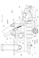
- FIG. 1 is a side view showing the whole of a passenger-type rice transplanter as a paddy field working machine according to the present invention.
- FIG. 2 is a plan view showing the entire passenger-type rice transplanter.
- the passenger-type rice transplanter is provided with a pair of left and right front wheels 1F and 1F that can be steered at the front of the traveling machine 1, and a pair of left and right drives are provided at the rear of the traveling machine 1. It is equipped with rear wheels 1R and 1R as wheels and is configured to run on its own. Power from the engine 20 provided in the driving portion 2 at the front of the fuselage is transmitted to the rear wheels 1R and 1R.
- the power of the engine 20 is connected to the fertilizer application device 4 described later mounted on the rear part of the traveling machine 1 and the rear part of the body frame 10 of the traveling machine 1 via an elevating link mechanism 11 capable of vertically swinging operation. It is also transmitted to the seedling planting device 6 as a ground work device.
- a ground leveling device 5 provided with a ground leveling rotor 50 that is rotationally driven around a rotation axis x1 along the left-right lateral direction is provided.
- the traveling machine 1 is provided with a driving unit 3 on the rear side of the driving unit 2.
- a control unit 31 having a steering handle 31a or the like is arranged in the front, and a driver's seat 32 is arranged in the rear, and the driver's seat 32 is mounted on the driving unit 3 for maneuvering. It is configured to be possible.
- a boarding / alighting step 35 used for boarding / alighting from the ground is provided below both lateral ends of the driving section step 30, a boarding / alighting step 35 used for boarding / alighting from the ground is provided.
- side step 22 connected to the front of the driving step 30 is provided on both left and right sides of the engine bonnet 21 in which the engine 20 is housed in the driving section 2. It is configured so that it can be transferred from the front side of the machine body through this side step 22.
- spare seedling mounting stands 12 are provided on the lateral outer sides of the left and right side step 22s.
- Marker devices 24 are also provided on both lateral sides of the front portion of the traveling machine body 1. In FIGS. 1 and 2, the marker device 24 is supported in a retracted posture along the front-rear direction of the traveling machine 1 and bent upward, but when marking a line as a traveling index on the field, the marker device 24 is upwardly bent. It is used in a posture in which the bent tip side is in the horizontal direction and the traveling machine body 1 extends laterally outward.
- the driver step 30 is formed so that the width in the left-right direction of the driver step 30 located on the front side of the driver seat 32 is not constant, and different portions are formed in the front and rear. That is, the left-right width of the driver step 30 at a position closer to the rear near the driver's seat 32 is formed wider than the left-right width of the driver step 30 at a position closer to the front far from the driver's seat 32. As a result, there is a narrow portion 33 that is slightly narrower in the left-right direction at a position closer to the front side far from the driver's seat 32, and left and right at a position closer to the rear side closer to the driver's seat 32 than the narrow portion 33.
- the width in the left-right direction of the narrow portion 33 is about the same as or slightly wider than the distance between the outermost sides of the side step 22 existing on both sides of the driving portion 2.
- the wide portion 34 is wider than that, wider than the left-right width of the hopper 40 of the fertilizer application device 4 arranged on the back of the driver's seat 32, and 10 rows of seedlings placed on the seedling planting device 6.
- the width is set so as not to exceed the width in the left-right direction of the seedling stand 60 having the portion 60a.
- the passenger-type rice transplanter is provided with a fertilizer application device 4 as an example of an agricultural material supply device.
- the fertilizer application device 4 includes a hopper 40 for storing powdered fertilizer, which is an example of agricultural materials, a feeding unit 41 for feeding out a predetermined amount of fertilizer stored from the hopper 40, and a transport hose 42 for transporting the fed out fertilizer. It is provided with a groove making device 43 as a ground supply unit that guides the supplied fertilizer to the field.
- the hopper 40 is formed by arranging five container units having a storage space for powdered fertilizer in a row in the left-right direction, and is located on the back side of the driver's seat 32 at the rear end of the traveling machine 1. It is provided.
- the seedling planting device 6 which is an example of the ground work device is connected to the rear end portion of the elevating link mechanism 11.
- the front end of the planting frame 61 of the seedling planting device 6 is connected to the rear end of the elevating link mechanism 11.
- Ten seedling planting mechanisms 62 mounted side by side in a row on the rear of the planting frame 61, a seedling stand 60 provided above the planting frame 61, and a lower portion of the planting frame 61. It is equipped with five grounding floats 63 mounted side by side in the horizontal direction of the traveling machine, and is configured for 10-row planting.
- the seedling placing table 60 is provided with ten seedling placing portions 60a arranged side by side in the traveling machine body and configured to place mat-shaped seedlings.
- the seedling stand 60 is supported on the front side corresponding to the back side of the seedling rest portion 60a by the seedling stand support frame 65 erected from the planting frame 61, and is configured to be reciprocating in the lateral direction of the machine body. ing.
- the seedling placing table 60 is reciprocated in conjunction with the seedling planting operation of the seedling planting mechanism 62, and seedlings are supplied to each seedling planting mechanism 62 from the seedling placing portion 60a.
- Engine power is transmitted to the seedling planting device 6 from the traveling machine body 1 side via the planting drive shaft 13.
- the rear part of the seedling planting device 6 is equipped with a chemical spraying device 64 for spraying the chemicals to the field after planting the seedlings.
- Each grounding float 63 is in contact with the field scene in the descending work state of the seedling planting device 6, and supports the seedling planting device 6 so that the seedling planting depth by each seedling planting mechanism 62 becomes a predetermined depth. In addition, the ground is leveled in the immediate vicinity of the seedling planting site by the seedling planting mechanism 62.
- a groove making device 43 for cutting a groove for guiding the fertilizer supplied from the fertilizer application device 4 to the mud surface and embedding it is attached to each of the grounding floats 63.
- the seedling planting device 6 includes a plurality of seedling placing portions 60a arranged in a horizontal row along the left-right direction, a plurality of seedling planting mechanisms 62 arranged corresponding to the seedling placing portions 60a, and seedlings.
- the seedling planting units 6R and 6L which are composed of a combination of the mounting portion 60a and the planting frame 61 supporting the seedling planting mechanism 62, are provided on the right side and the left side in the left-right direction.
- the seedling planting units 6R and 6L are connected to the elevating link mechanism 11 via a folding mechanism 7.
- the folding mechanism 7 is connected to the central frame 70C supported by the elevating link mechanism 11 and the right end portion of the central frame 70C so as to be relatively rotatable around the vertical axis y1.
- the right end frame 70R and the left end frame 70L connected to the left end of the center frame 70C so as to be relatively rotatable around the vertical axis y2 are provided.
- the planting frame 61 in the right side seedling planting unit 6R and the left side seedling planting unit 6L. , 61 are supported so as to be relatively swingable around the vertical axis y3 and y4 parallel to the vertical axis y1 and y2.
- the ground leveling device 5 arranged in front of the seedling planting device 6 will be described.
- the ground leveling device 5 is used for the purpose of leveling unevenness of the mud surface and soil mass at a position in front of the grounding float 63 of the seedling planting device 6 in the traveling direction, and is around the rotation axis x1 in the left-right lateral direction. It is provided with a ground leveling rotor 50 that is rotationally driven by the ground leveling rotor 50, a ground leveling transmission shaft 14 that transmits power to the ground leveling rotor 50, and an elevating mechanism 54 that changes the ground height of the ground leveling rotor 50.
- the ground leveling rotor 50 includes a central rotating body portion 50C located in the central portion in the left-right direction, and end rotating body portions 50R arranged on both left and right sides in a direction along the rotation axis x1 of the central rotating body portion 50C. It is equipped with 50L.
- the ground leveling transmission shaft 14 extending from the traveling machine body 1 side is connected to the central rotating body portion 50C, and the power of the engine 20 is transmitted to the central rotating body portion 50C.
- the central rotating body portion 50C and the end rotating body portions 50R and 50L have a central driving shaft 51C supporting the central rotating body portion 50C and left and right end portions. It is provided with end rotation shafts 51R and 51L that support the rotating body portions 50R and 50L.
- These central drive shafts 51C and end rotation shafts 51R and 51L are composed of square shafts having a substantially square rectangular cross section. A large number of synthetic resin ground leveling rotating bodies 52 having square hole-shaped fitting holes 52a are fitted to the central drive shaft 51C and the end rotating shafts 51R and 51L configured by the square shaft.
- the central drive shaft 51C and the central rotating body portion 50C are configured to be integrally rotatable, and the left and right end rotating body portions 50R and 50L are fitted to the end rotating shafts 51R and 51L so as to be integrally rotatable. It has been done.
- the ground leveling transmission shaft 14 and the central drive shaft 51C are interlocked and connected via a bevel gear transmission mechanism (not shown).
- the central drive shaft 51C and the end rotation shafts 51R and 51L are engaged and disengaged by relative movement in the axial direction via the meshing clutch 53 provided at each other's shaft end, and the power is transmitted.
- the disconnection state can be switched. Since a large drive load as in the case of driving a wheel for traveling does not act on the ground leveling rotor 50, the engagement change between the central drive shaft 51C side and the end rotation shafts 51R and 51L in the meshing clutch 53 is It is set relatively shallow.
- the right end frame 70R and the left end frame 70L rotate around the vertical axis y1 and y2 to change to the folding storage posture by the folding mechanism 7, the right end frame 70R and the left end frame 70L are linked to the operation of the center frame 70C.
- the meshing clutch 53 changes from the meshing state to the disengaged state, and the power transmission from the central drive shaft 51C to the end rotation shafts 51R and 51L is cut off.
- the right end frame 70R and the left end frame 70L in the folded storage posture are rotated around the vertical axis y1 and y2 in the opposite direction to the previous ones, and the end rotation shafts 51R and 51L are rotated.
- the elevating mechanism 54 that changes the ground height of the ground leveling rotor 50 includes a central suspension link mechanism 54C (corresponding to a suspension link mechanism) that supports the central drive shaft 51C, and left and right end rotation shafts 51R and 51L. It is provided with supporting end suspension link mechanisms 54R and 54L (corresponding to another suspension link mechanism) and an actuator 55 for raising and lowering the central suspension link mechanism 54C.
- the central drive shaft 51C is supported by the central frame 70C so as to be able to move up and down via the central suspension link mechanism 54C, and the left and right end rotation shafts 51R and 51L are moved up and down via the end suspension link mechanism 54R and 54L. It is supported by the left and right seedling planting units 6R and 6L as much as possible.
- the central suspension link mechanism 54C and the end suspension link mechanisms 54R and 54L are provided at both ends of the central drive shaft 51C via a pair of left and right refraction link members 56 having a boss portion 56a with a bearing at the lower end portion. And both ends of the end rotation shafts 51R and 51L are supported.
- the refraction link member 56 has fixed ends on the opposite side of the boss portion 56a fixed to the central frame 70C at both ends of the central drive shaft 51C, and a planting frame at both ends of the end rotation shafts 51R and 51L. It is fixed at 61.
- the central suspension link mechanism 54C transmits the operating power of the actuator 55 composed of an electric motor fixed to the seedling stand support frame 65.
- the rotation of the actuator 55 is transmitted to the refraction link member 56 via the sector gear 55a, the bell crank 55b, the operation rod 55c, etc., and the central drive shaft 51C can be raised and lowered.
- the intermediate position of the bell crank 55b is fixed to the link operation shaft 57, and the left and right central suspension link mechanisms 54C are simultaneously operated via the link operation shaft 57.
- Both ends of the link operation shaft 57 and the opposite ends of the operation interlocking shafts 58 and 58 of the end suspension link mechanisms 54R and 54L facing the link operation shaft 57 are engaged with each other and rotate integrally.
- the engagement mechanism 59 is provided.
- the engagement mechanism 59 is disengaged (see FIG. 10) and the operation interlocking shafts 58 and 58 can rotate freely. That is, when the end rotating body portions 50R, 50L and the end suspending link mechanism 54R, 54L are laterally moved so as to be separated from the central rotating body portion 50C and the central suspending link mechanism 54C, the meshing clutch 53 is in the disengaged state.
- the interlocking by the engaging mechanism 59 is released.
- the engagement / disengagement of the link operation shaft 57 and the operation interlocking shafts 58, 58 by the engagement mechanism 59 is also performed in the same manner as in the case of disengagement of the meshing clutch 53. That is, the folding mechanism 7 engages and disengages the right end frame 70R and the left end frame 70L with respect to the center frame 70C as they rotate around the vertical axis y1 and y2.
- the right end frame 70R and the left end frame 70L supporting the left and right seedling planting units 6R and 6L are mounted on the vertical shafts.
- the left and right seedling planting units 6R and 6L are moved from the working state shown in FIG. 3 to the retracted state shown in FIG. Can be folded.
- the end rotating body portions 50R and 50L are in a state of slipping below the central rotating body portion 50C, and are in a compactly folded state.
- the reason why the end rotating body portions 50R and 50L can be moved to the lower position in this way is that the operation interlocking shaft 58 is disengaged by the engaging mechanism 59 and disengaged from the link operating shaft 57.
- 58 is in a free rotation state. That is, by driving the actuator 55, the end suspension link mechanisms 54R and 54L, which were lifted together with the link operation shaft 57 in the state shown by the virtual line in FIG. 9, are disengaged from the link operation shaft 57. This is due to the fact that the state shown by the solid line in FIG. 9 is greatly hung down.
- the engagement / disengagement of the meshing clutch 53 and the engagement / disengagement of the engagement mechanism 59 are performed by the folding mechanism 7 on the vertical axis y1 of the right end frame 70R and the left end frame 70L with respect to the center frame 70C.
- An example is shown in which the meshing clutch 53 and the engagement mechanism 59 have a shallow engagement change so as to be performed with rotation around y2, but the structure is not necessarily limited to this structure, and the changeover is compared.
- the engagement clutch 53 By deepening the target and pulling out the end rotation shafts 51R, 51L and the operation interlocking shafts 58, 58 laterally and outward by artificial operation, the engagement clutch 53 can be engaged and disengaged, and the engagement mechanism 59 can be engaged and disengaged. You may do it.
- the same configurations as those in the above-described embodiment may be adopted.
- the central rotating body portion 50C has a structure in which the central drive shaft 51C and the end rotating shafts 51R and 51L are configured by a square axis so that rotational power is transmitted to the ground leveling rotating body 52.
- the end rotating body portions 50R and 50L but the structure is not necessarily limited to this.
- the ground leveling rotating body 52 may be directly adhered to the central drive shaft 51C and the end rotating shafts 51R and 51L, or a shaft having a cross-sectional shape other than the square shaft may be used.
- the same configurations as those in the above-described embodiment may be adopted.
- a structure is exemplified in which the positions of the end rotating body portions 50R and 50L are lowered without changing the position of the central rotating body portion 50C at the time of folding. It is not limited to.
- the structure may be such that the position of the central rotating body portion 50C is raised or lowered without changing the positions of the end rotating body portions 50R and 50L.
- the same configurations as those in the above-described embodiment may be adopted.
- the actuator 55 which is the drive source of the elevating mechanism 54
- the actuator 55 is provided only at a position acting on the central suspension link mechanism 54C for elevating and lowering the central rotating body portion 50C.
- the structure is not necessarily limited to this, and for example, it may be provided at a position acting on the end suspension link mechanisms 54R and 54L that raise and lower the end rotating body portions 50R and 50L.
- the same configurations as those in the above-described embodiment may be adopted.
- the structure in which the central rotating body portion 50C and the end rotating body portions 50R and 50L are supported by the seedling planting device 6 via the folding mechanism 7 is exemplified, but this is not necessarily the case. It is not limited to the structure.
- the end rotating body portions 50R and 50L may be configured to be separable with respect to the central rotating body portion 50C without going through the folding mechanism 7.
- the same configurations as those in the above-described embodiment may be adopted.
- the present invention is not limited to a rice transplanter for 10-row planting, but is also applicable to a rice transplanter for 8-row planting with less than 10 rows and a rice transplanter with more rows than 10 rows.
Landscapes
- Life Sciences & Earth Sciences (AREA)
- Transplanting Machines (AREA)
- Soil Sciences (AREA)
- Environmental Sciences (AREA)
- Agricultural Machines (AREA)
- Soil Working Implements (AREA)
Abstract
整地用ロータの分割を、苗植付装置に装着した状態のままで行えるようにした水田作業機を提供する。複数の苗載置部と、複数の苗植付機構と、植付フレームと、の組み合わせで構成される苗植付ユニット6L,6Rが、左右方向での右側と左側とに分割可能に備えられ、苗植付ユニット6R,6Lが、昇降リンク機構11に連結されており、整地用ロータ50が、左右方向での中央部に位置する中央回転体部分50Cと、その中央回転体部分50Cの回転軸心に沿う方向で左右両側に配置される端部回転体部分50R,50Lとを備えて、中央回転体部分50Cに対して左右の端部回転体部分50R,50Lを分割可能に構成され、中央回転体部分50Cが昇降リンク機構11に支持され、左右の端部回転体部分50R,50Lが左右の対応する苗植付ユニット6R,6Lに支持されている。
Description
本発明は、苗植付装置の前方に、左右横方向に沿う回転軸心周りで回転駆動する整地用ロータが備えられた整地装置を有する水田作業機に関する。
苗植付装置の前方に整地用ロータを備える整地装置が配設された水田作業機としては、従来では、次のように構成されたものが知られている。
苗植付装置の前部に整地装置を配設してあり、苗植付装置の駆動系から整地用ロータの駆動軸の一端部に回転動力が入力され、整地用ロータの駆動回転によって、苗植付装置による苗植え付け作業前の圃場を整地するように構成されていた(特許文献1参照)。
苗植付装置の前部に整地装置を配設してあり、苗植付装置の駆動系から整地用ロータの駆動軸の一端部に回転動力が入力され、整地用ロータの駆動回転によって、苗植付装置による苗植え付け作業前の圃場を整地するように構成されていた(特許文献1参照)。
特許文献1に記載の水田作業機では、苗植付装置の前部に整地用ロータを配設して、苗植え付け作業前の圃場を整地し得る点では有用なものである。
しかしながら、このような構造では、苗植付装置として植付条数が大きいものを採用し、格納や運搬のために苗植付装置を分割したり、折り畳み可能な構造とした場合に、整地用ロータを分割、あるいは折り畳むことができず、取り外すなどの作業が必要となる点で改善の余地がある。
しかしながら、このような構造では、苗植付装置として植付条数が大きいものを採用し、格納や運搬のために苗植付装置を分割したり、折り畳み可能な構造とした場合に、整地用ロータを分割、あるいは折り畳むことができず、取り外すなどの作業が必要となる点で改善の余地がある。
本発明は、整地用ロータの分割を、苗植付装置に対する装着状態を維持したままで行えるようにした水田作業機を提供しようとするものである。
本発明の水田作業機は、
走行機体の後方に昇降リンク機構を介して連結支持された苗植付装置と、
前記苗植付装置の前方において、左右横方向に沿う回転軸心周りで回転駆動される整地用ロータと、が配設され、
前記苗植付装置は、左右方向に沿って横一列に配置された複数の苗載置部と、前記苗載置部に対応して配置された複数の苗植付機構と、前記苗載置部及び前記苗植付機構を支持する植付フレームと、の組み合わせで構成される苗植付ユニットが、左右方向での右側と左側とに分割可能に備えられ、
前記苗植付ユニットが、前記昇降リンク機構に連結されており、
前記整地用ロータが、左右方向での中央部に位置する中央回転体部分と、その中央回転体部分の回転軸心に沿う方向で左右両側に配置される端部回転体部分とを備えて、前記中央回転体部分に対して左右の前記端部回転体部分を分割可能に構成され、
前記中央回転体部分が前記昇降リンク機構に支持され、左右の前記端部回転体部分が左右の対応する前記苗植付ユニットに支持されていることを特徴とする。
走行機体の後方に昇降リンク機構を介して連結支持された苗植付装置と、
前記苗植付装置の前方において、左右横方向に沿う回転軸心周りで回転駆動される整地用ロータと、が配設され、
前記苗植付装置は、左右方向に沿って横一列に配置された複数の苗載置部と、前記苗載置部に対応して配置された複数の苗植付機構と、前記苗載置部及び前記苗植付機構を支持する植付フレームと、の組み合わせで構成される苗植付ユニットが、左右方向での右側と左側とに分割可能に備えられ、
前記苗植付ユニットが、前記昇降リンク機構に連結されており、
前記整地用ロータが、左右方向での中央部に位置する中央回転体部分と、その中央回転体部分の回転軸心に沿う方向で左右両側に配置される端部回転体部分とを備えて、前記中央回転体部分に対して左右の前記端部回転体部分を分割可能に構成され、
前記中央回転体部分が前記昇降リンク機構に支持され、左右の前記端部回転体部分が左右の対応する前記苗植付ユニットに支持されていることを特徴とする。
本発明によると、整地用ロータが、中央回転体部分に対して左右の端部回転体部分を分割可能に構成されている。そして、中央回転体部分は昇降リンク機構に支持され、左右の端部回転体部分は、左右の対応する苗植付ユニットに支持されている。
したがって、左右の端部回転体部分を中央回転体部分に対して分割された状態としても、中央回転体部分は昇降リンク機構に、左右の端部回転体部分は、左右の対応する苗植付ユニットに、それぞれ支持され、苗植付装置に対する装着状態を維持したままでの分割が可能となる。
これによって、水田作業機において、整地用ロータの取り外しや取り付け作業を要さず、苗植付装置に支持された状態を維持しながら整地用ロータも分割された状態とすることができ、格納や運搬を便利に行うことができる。
したがって、左右の端部回転体部分を中央回転体部分に対して分割された状態としても、中央回転体部分は昇降リンク機構に、左右の端部回転体部分は、左右の対応する苗植付ユニットに、それぞれ支持され、苗植付装置に対する装着状態を維持したままでの分割が可能となる。
これによって、水田作業機において、整地用ロータの取り外しや取り付け作業を要さず、苗植付装置に支持された状態を維持しながら整地用ロータも分割された状態とすることができ、格納や運搬を便利に行うことができる。
本発明において、前記苗植付ユニットが、前記昇降リンク機構に対して折り畳み機構を介して連結されており、
前記折り畳み機構は、前記昇降リンク機構に支持された中央フレームと、その中央フレームの右端部に上下軸心回りで相対回動可能に連結された右端部フレームと、前記中央フレームの左端部に上下軸心回りで相対回動可能に連結された左端部フレームと、が備えられ、
前記右端部フレーム及び前記左端部フレームにおける前記中央フレームに連結された側とは反対側の端部に、右側の前記苗植付ユニット及び左側の前記苗植付ユニットにおける前記植付フレームが、前記中央フレームにおける左右の前記上下軸心と平行な上下軸心回りで相対揺動可能に支持されていると好適である。
前記折り畳み機構は、前記昇降リンク機構に支持された中央フレームと、その中央フレームの右端部に上下軸心回りで相対回動可能に連結された右端部フレームと、前記中央フレームの左端部に上下軸心回りで相対回動可能に連結された左端部フレームと、が備えられ、
前記右端部フレーム及び前記左端部フレームにおける前記中央フレームに連結された側とは反対側の端部に、右側の前記苗植付ユニット及び左側の前記苗植付ユニットにおける前記植付フレームが、前記中央フレームにおける左右の前記上下軸心と平行な上下軸心回りで相対揺動可能に支持されていると好適である。
本構成によると、苗植付装置が折り畳み機構を備えて折り畳み可能に構成されていることを利用して、整地用ロータを、苗植付装置に支持された状態を維持したままで折り畳めるようにしてある。
すなわち、苗植付装置の折り畳み仕様であるところの、中央フレームと、左右両側の苗植付ユニットと、の三分割部分を、昇降リンク機構に支持された中央フレーム部分に対して、左右両端側の苗植付ユニット部分が折り畳み可能である構造を合わせて、整地用ロータも、中央回転体部分と、両側の端部回転体部分と、の三分割構造を採用している。
その結果、苗植付装置の折り畳み動作に伴って、苗植付装置に支持された状態を維持しながら整地用ロータの折り畳みが行われる。
これにより、折り畳み可能な水田作業機において、整地用ロータの取り外しや取付作業を必要とせず、苗植付装置に支持された状態を維持しながら整地用ロータも折り畳み姿勢に変更することができ、格納や運搬に際しての作業性の向上を図ることができる。
すなわち、苗植付装置の折り畳み仕様であるところの、中央フレームと、左右両側の苗植付ユニットと、の三分割部分を、昇降リンク機構に支持された中央フレーム部分に対して、左右両端側の苗植付ユニット部分が折り畳み可能である構造を合わせて、整地用ロータも、中央回転体部分と、両側の端部回転体部分と、の三分割構造を採用している。
その結果、苗植付装置の折り畳み動作に伴って、苗植付装置に支持された状態を維持しながら整地用ロータの折り畳みが行われる。
これにより、折り畳み可能な水田作業機において、整地用ロータの取り外しや取付作業を必要とせず、苗植付装置に支持された状態を維持しながら整地用ロータも折り畳み姿勢に変更することができ、格納や運搬に際しての作業性の向上を図ることができる。
本発明において、前記中央回転体部分を支持する中央駆動軸と、左右の前記端部回転体部分を支持する端部回転軸と、が備えられ、前記端部回転軸が前記中央駆動軸に対して、係脱可能なクラッチ機構を介して、前記中央駆動軸に対する軸同士の連結を解除可能に連結され、
前記中央駆動軸が吊り下げリンク機構を介して昇降可能に前記中央フレームに支持され、左右の前記端部回転軸が、別の吊り下げリンク機構を介して昇降可能に左右の前記苗植付ユニットに支持され、
前記中央駆動軸に前記走行機体からの動力が入力されるとともに、前記中央駆動軸の吊り下げリンク機構を昇降作動させるアクチュエータが前記中央フレームに取り付けられていると好適である。
前記中央駆動軸が吊り下げリンク機構を介して昇降可能に前記中央フレームに支持され、左右の前記端部回転軸が、別の吊り下げリンク機構を介して昇降可能に左右の前記苗植付ユニットに支持され、
前記中央駆動軸に前記走行機体からの動力が入力されるとともに、前記中央駆動軸の吊り下げリンク機構を昇降作動させるアクチュエータが前記中央フレームに取り付けられていると好適である。
本構成によると、中央フレームに吊り下げリンク機構を介して中央回転体部分の中央駆動軸が支持され、左右の苗植付ユニットに別の吊り下げリンク機構を介して左右の端部回転体部分の端部回転軸が支持されている。そして、端部回転軸と中央駆動軸は、係脱可能なクラッチ機構を介して、軸同士の連結を解除可能に連結され、かつ、中央駆動軸の吊り下げリンク機構を昇降作動させるアクチュエータが中央フレームに取り付けられている。
したがって、クラッチ機構により端部回転軸と中央駆動軸との連結を解除すると、端部回転軸及び端部回転体部分は、回転動力の伝達やアクチュエーの吊り上げ動力は伝達されていないが、別の吊り下げリンク機構を介して左右両端側の苗植付ユニット部分に対して吊り下げられた状態を保っている。
これにより、折り畳み可能な水田作業機において、整地用ロータの取り外しや取付作業を必要とせず、アクチュエータで中央駆動軸の高さを適切に調節するなどして、整地用ロータが苗植付装置に吊り下げ支持された状態を維持しながら、容易に折り畳み姿勢に変更することができ、格納や運搬に際してのさらなる作業性の向上を図ることができる。
したがって、クラッチ機構により端部回転軸と中央駆動軸との連結を解除すると、端部回転軸及び端部回転体部分は、回転動力の伝達やアクチュエーの吊り上げ動力は伝達されていないが、別の吊り下げリンク機構を介して左右両端側の苗植付ユニット部分に対して吊り下げられた状態を保っている。
これにより、折り畳み可能な水田作業機において、整地用ロータの取り外しや取付作業を必要とせず、アクチュエータで中央駆動軸の高さを適切に調節するなどして、整地用ロータが苗植付装置に吊り下げ支持された状態を維持しながら、容易に折り畳み姿勢に変更することができ、格納や運搬に際してのさらなる作業性の向上を図ることができる。
本発明において、前記端部回転体部分は、前記クラッチ機構による軸同士の連結が解除された状態で、前記中央回転体部分よりも下方へ移動可能に構成されていると好適である。
本構成によると、端部回転体部分が中央回転体部分よりも下方へ移動可能に構成されているので、端部回転体部分が中央回転体部分の下側へ潜り混むようにしてコンパクトに折り畳み可能となる。
本発明において、前記苗植付ユニットが整地用フロートを備え、前記端部回転体部分は、前記クラッチ機構による軸同士の連結が解除された状態で、前記整地用フロートよりも下方へ移動可能に構成されていると好適である。
本構成によると、端部回転体部分が整地用フロートよりも下方へ移動可能に構成されているので、水平方向で整地用フロートとの干渉を避けるように前後方向に移動させるなどの必要もなく、コンパクトに折り畳み可能となる。
本発明において、前記中央回転体部分は、前記クラッチ機構による軸同士の連結が解除された状態で、前記端部回転体部分よりも上方へ移動可能に構成されていると好適である。
本構成によると、中央回転体部分を端部回転体部分よりも上方へ移動可能に構成してあるので、中央回転体部分の吊り下げリンク機構を昇降作動させるアクチュエータを利用して、中央回転体部分を楽な作業で持ち上げて、中央回転体部分が端部回転体部分の上側へ乗り上げるようにしてコンパクトに折り畳み可能となる。
本発明において、前記クラッチ機構は、前記中央回転体部分に対する前記端部回転体部分の姿勢変更に伴って入り切り変更可能に構成され、前記端部回転体部分の回転軸心が前記中央回転体部分の回転軸心に沿う姿勢でクラッチ入り状態となり、前記端部回転体部分の回転軸心が前記中央回転体部分の回転軸心から外れる方向への姿勢変更に伴って切り状態となるように構成されていると好適である。
本構成であれば、中央回転体部分に対する端部回転体部分の姿勢変更に伴ってクラッチ機構を入り切りさせることができ、折り畳み作業をより一層簡単に行い易い。
本発明において、前記苗植付装置は、10条用の前記苗載置部を備えた10条植え用のものであると好適である。
本構成によれば、10条用の苗載置部を備えた大きな苗植付装置の折り畳みに伴う整地用ロータの折り畳み作業を容易に行い易い。
以下、本発明の実施形態の一例を図面の記載に基づいて説明する。
尚、本実施形態での説明における前後方向及び左右方向は、特段の説明がない限り、次のように記載している。つまり、本発明を適用した水田作業機において、走行機体の作業走行時における前進側の進行方向(図1,2における矢印F参照)が「前」、後進側への進行方向(図1,2における矢印B参照)が「後」、その前後方向での前向き姿勢を基準としての右側に相当する方向(図2における矢印R参照)が「右」、同様に左側に相当する方向(図2における矢印L参照)が「左」である。
尚、本実施形態での説明における前後方向及び左右方向は、特段の説明がない限り、次のように記載している。つまり、本発明を適用した水田作業機において、走行機体の作業走行時における前進側の進行方向(図1,2における矢印F参照)が「前」、後進側への進行方向(図1,2における矢印B参照)が「後」、その前後方向での前向き姿勢を基準としての右側に相当する方向(図2における矢印R参照)が「右」、同様に左側に相当する方向(図2における矢印L参照)が「左」である。
〔水田作業機の全体構成〕
図1は、本発明に係る水田作業機としての乗用型田植機の全体を示す側面図である。図2は、乗用型田植機の全体を示す平面図である。
これらの図1,2に示すように、乗用型田植機は、走行機体1の前部に左右一対の操向操作自在な前車輪1F,1Fを備え、走行機体1の後部に左右一対の駆動輪としての後車輪1R,1Rを備えて、自走するように構成されている。
後車輪1R,1Rへは、機体前部の原動部2に設けたエンジン20からの動力が伝達される。このエンジン20の動力は、走行機体1の後部に搭載された後述する施肥装置4、及び走行機体1の機体フレーム10の後部に、上下揺動操作自在な昇降リンク機構11を介して連結された対地作業装置としての苗植付装置6にも伝達される。苗植付装置6の前方には、左右横方向に沿う回転軸心x1周りで回転駆動される整地用ロータ50を備えた整地装置5が設けられている。
図1は、本発明に係る水田作業機としての乗用型田植機の全体を示す側面図である。図2は、乗用型田植機の全体を示す平面図である。
これらの図1,2に示すように、乗用型田植機は、走行機体1の前部に左右一対の操向操作自在な前車輪1F,1Fを備え、走行機体1の後部に左右一対の駆動輪としての後車輪1R,1Rを備えて、自走するように構成されている。
後車輪1R,1Rへは、機体前部の原動部2に設けたエンジン20からの動力が伝達される。このエンジン20の動力は、走行機体1の後部に搭載された後述する施肥装置4、及び走行機体1の機体フレーム10の後部に、上下揺動操作自在な昇降リンク機構11を介して連結された対地作業装置としての苗植付装置6にも伝達される。苗植付装置6の前方には、左右横方向に沿う回転軸心x1周りで回転駆動される整地用ロータ50を備えた整地装置5が設けられている。
走行機体1は、原動部2の後方側に運転部3を備えている。この運転部3では、運転部ステップ30上で、前方にステアリングハンドル31a等を備えた操縦部31が配設され、後方に運転座席32が配設されて、運転部3に搭乗して操縦することが可能であるように構成されている。運転部ステップ30の両横端部の下方には、地上から乗降する際に使用される乗降用ステップ35が設けられている。
図2に示すように、原動部2においてエンジン20を内装するエンジンボンネット21の左右両側には、運転部ステップ30の前方に連なる側部ステップ22が設けられている。この側部ステップ22を通って、機体前方側から乗り移り可能であるように構成されている。
図1,2に示すように、走行機体1の前部で、左右の側部ステップ22の横外側に予備苗載せ台12が設けられている。
走行機体1の前部の両横側には、マーカ装置24も設けられている。このマーカ装置24は、図1,2では、走行機体1の前後方向に沿い、かつ、上方へ折り曲げた格納姿勢で支持されているが、走行指標となる線を圃場にマーキングするときには、上方へ折り曲げていた先端側を水平方向にして、かつ走行機体1の横外方へ延出した姿勢で使用する。
図1,2に示すように、走行機体1の前部で、左右の側部ステップ22の横外側に予備苗載せ台12が設けられている。
走行機体1の前部の両横側には、マーカ装置24も設けられている。このマーカ装置24は、図1,2では、走行機体1の前後方向に沿い、かつ、上方へ折り曲げた格納姿勢で支持されているが、走行指標となる線を圃場にマーキングするときには、上方へ折り曲げていた先端側を水平方向にして、かつ走行機体1の横外方へ延出した姿勢で使用する。
図2に示すように、運転部ステップ30は、運転座席32よりも前方側箇所の運転部ステップ30における左右方向の幅が一定ではなく、前後で異なる部分が生じるように形成されている。つまり、運転座席32に近い後方寄りの位置における運転部ステップ30の左右方向幅が、運転座席32から遠い前方側寄りの位置における運転部ステップ30の左右方向幅よりも広く形成されている。これによって、運転座席32から遠い前方側寄りの位置には、左右方向幅が少し狭い幅狭部分33が存在し、運転座席32に近い後方寄りの位置には、前記幅狭部分33よりも左右方向幅が広い幅広部分34が存在する。
より具体的には、幅狭部分33の左右方向幅は、原動部2の両脇に存在する側部ステップ22の最外側間の距離と同程度か、それよりも少し広い程度である。幅広部分34は、それよりも幅広で、運転座席32の背部に配設される施肥装置4のホッパー40の左右方向幅よりも広く、かつ苗植付装置6が備える10条分の苗載置部60aを有した苗載せ台60の左右方向幅を越えない程度の幅に設定されている。
より具体的には、幅狭部分33の左右方向幅は、原動部2の両脇に存在する側部ステップ22の最外側間の距離と同程度か、それよりも少し広い程度である。幅広部分34は、それよりも幅広で、運転座席32の背部に配設される施肥装置4のホッパー40の左右方向幅よりも広く、かつ苗植付装置6が備える10条分の苗載置部60aを有した苗載せ台60の左右方向幅を越えない程度の幅に設定されている。
乗用型田植機には、農用資材供給装置の一例としての施肥装置4が設けられている。
施肥装置4は、農用資材の一例である粉末肥料を貯留するホッパー40と、ホッパー40から貯留されている肥料を所定量ずつ繰り出す繰り出し部41と、繰り出された肥料を搬送する搬送用ホース42と、供給された肥料を圃場へ案内する対地供給部としての作溝器43と、を備えている。
ホッパー40は、粉末肥料の収容空間を有した5個の容器単位体が左右方向で列状に並べられたものであり、運転座席32の背部側に位置して走行機体1の後端部に設けられている。
施肥装置4は、農用資材の一例である粉末肥料を貯留するホッパー40と、ホッパー40から貯留されている肥料を所定量ずつ繰り出す繰り出し部41と、繰り出された肥料を搬送する搬送用ホース42と、供給された肥料を圃場へ案内する対地供給部としての作溝器43と、を備えている。
ホッパー40は、粉末肥料の収容空間を有した5個の容器単位体が左右方向で列状に並べられたものであり、運転座席32の背部側に位置して走行機体1の後端部に設けられている。
〔苗植付装置〕
図1,2に示すように、対地作業装置の一例である苗植付装置6は、昇降リンク機構11の後端部に連結されている。
昇降リンク機構11の後端部には、苗植付装置6の植付フレーム61の前端部が連結されている。植付フレーム61の後部に走行機体横方向に一列に並べて取り付けられた10個の苗植付機構62と、植付フレーム61の上方に設けられた苗載せ台60と、植付フレーム61の下部に走行機体横方向に並べて取り付けられた5つの接地フロート63と、が備えられて10条植え用に構成されている。
図1,2に示すように、対地作業装置の一例である苗植付装置6は、昇降リンク機構11の後端部に連結されている。
昇降リンク機構11の後端部には、苗植付装置6の植付フレーム61の前端部が連結されている。植付フレーム61の後部に走行機体横方向に一列に並べて取り付けられた10個の苗植付機構62と、植付フレーム61の上方に設けられた苗載せ台60と、植付フレーム61の下部に走行機体横方向に並べて取り付けられた5つの接地フロート63と、が備えられて10条植え用に構成されている。
苗載せ台60は、走行機体横方向に並び、マット状苗を載置するよう構成された10個の苗載置部60aを備えている。苗載せ台60は、植付フレーム61から立設された苗載せ台支持枠65によって、苗載置部60aの背面側に相当する正面側を支持され、機体横方向に往復移動自在に構成されている。苗載せ台60は、苗植付機構62の苗植え動作に連動して往復移送され、各苗植付機構62に苗載置部60aから苗供給する。
苗植付装置6へは、走行機体1側から植付駆動軸13を介してエンジン動力が伝達される。苗植付装置6の後部には、苗植付後の圃場へ薬剤を散布する薬剤散布装置64が装備されている。
苗植付装置6へは、走行機体1側から植付駆動軸13を介してエンジン動力が伝達される。苗植付装置6の後部には、苗植付後の圃場へ薬剤を散布する薬剤散布装置64が装備されている。
各接地フロート63は、苗植付装置6の下降作業状態において、圃場面に接地して、各苗植付機構62による苗植深さが所定深さになるように苗植付装置6を支持し、かつ苗植付機構62による苗植え箇所の直近を整地する。
各接地フロート63のそれぞれに、施肥装置4から供給される肥料を泥面に案内して埋入させるための溝を切る作溝器43が取り付けられている。
各接地フロート63のそれぞれに、施肥装置4から供給される肥料を泥面に案内して埋入させるための溝を切る作溝器43が取り付けられている。
苗植付装置6は、左右方向に沿って横一列に配置された複数の苗載置部60aと、その苗載置部60aに対応して配置された複数の苗植付機構62と、苗載置部60a及び苗植付機構62を支持する植付フレーム61と、の組み合わせで構成される苗植付ユニット6R,6Lが、左右方向での右側と左側とに備えられている。
各苗植付ユニット6R,6Lは、昇降リンク機構11に対して折り畳み機構7を介して連結されている。
各苗植付ユニット6R,6Lは、昇降リンク機構11に対して折り畳み機構7を介して連結されている。
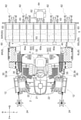
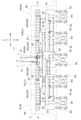
図3及び図4に示すように、折り畳み機構7は、昇降リンク機構11に支持された中央フレーム70Cと、その中央フレーム70Cの右端部に上下軸心y1回りで相対回動可能に連結された右端部フレーム70Rと、中央フレーム70Cの左端部に上下軸心y2回りで相対回動可能に連結された左端部フレーム70Lと、を備えている。
そして、右端部フレーム70R及び左端部フレーム70Lにおける前記中央フレーム70Cに連結された側とは反対側の端部に、右側の苗植付ユニット6R及び左側の苗植付ユニット6Lにおける植付フレーム61,61が前記上下軸心y1,y2と平行な上下軸心y3,y4回りで相対揺動可能に支持されている。
そして、右端部フレーム70R及び左端部フレーム70Lにおける前記中央フレーム70Cに連結された側とは反対側の端部に、右側の苗植付ユニット6R及び左側の苗植付ユニット6Lにおける植付フレーム61,61が前記上下軸心y1,y2と平行な上下軸心y3,y4回りで相対揺動可能に支持されている。
〔整地装置〕
苗植付装置6の前方に配置される整地装置5について説明する。
整地装置5は、苗植付装置6の接地フロート63よりも進行方向の前方箇所において、泥面の凹凸や土塊を均す目的で使用されるものであり、左右横方向の回転軸心x1周りで回転駆動される整地用ロータ50と、整地用ロータ50に対して動力を伝達する整地用伝動軸14と、整地用ロータ50の対地高さを変更する昇降機構54と、を備えている。
苗植付装置6の前方に配置される整地装置5について説明する。
整地装置5は、苗植付装置6の接地フロート63よりも進行方向の前方箇所において、泥面の凹凸や土塊を均す目的で使用されるものであり、左右横方向の回転軸心x1周りで回転駆動される整地用ロータ50と、整地用ロータ50に対して動力を伝達する整地用伝動軸14と、整地用ロータ50の対地高さを変更する昇降機構54と、を備えている。
整地用ロータ50は、左右方向での中央部に位置する中央回転体部分50Cと、その中央回転体部分50Cの回転軸心x1に沿う方向で左右両側に配置される端部回転体部分50R,50Lと、を備えている。走行機体1側から延出された整地用伝動軸14は、中央回転体部分50Cに接続され、エンジン20の動力が中央回転体部分50Cに伝達される。
図6及び図10,11に示されているように、中央回転体部分50C、及び端部回転体部分50R,50Lは、中央回転体部分50Cを支持する中央駆動軸51C、及び左右の端部回転体部分50R,50Lを支持する端部回転軸51R,51Lを備えている。
これらの中央駆動軸51C、及び端部回転軸51R,51Lは、ほぼ正方形の矩形断面を有した角軸で構成されている。この角軸で構成された中央駆動軸51C、及び端部回転軸51R,51Lに、角穴状の嵌合孔52aを形成した合成樹脂製の多数の整地回転体52を嵌合させてある。これによって、中央駆動軸51Cと中央回転体部分50Cとを一体回転可能に構成し、端部回転軸51R,51Lに左右の端部回転体部分50R,50Lを嵌合させて一体回転可能に構成してある。
これらの中央駆動軸51C、及び端部回転軸51R,51Lは、ほぼ正方形の矩形断面を有した角軸で構成されている。この角軸で構成された中央駆動軸51C、及び端部回転軸51R,51Lに、角穴状の嵌合孔52aを形成した合成樹脂製の多数の整地回転体52を嵌合させてある。これによって、中央駆動軸51Cと中央回転体部分50Cとを一体回転可能に構成し、端部回転軸51R,51Lに左右の端部回転体部分50R,50Lを嵌合させて一体回転可能に構成してある。
整地用伝動軸14と中央駆動軸51Cは、図示しないベベルギヤ伝動機構を介して連動連結されている。中央駆動軸51Cと端部回転軸51R,51Lとは、互いの軸端部に備えた噛み合いクラッチ53を介して、軸方向での相対移動によってクラッチの断接が行われ、動力の伝達状態と切断状態とが切り替えられる。
整地用ロータ50には、走行用の車輪を駆動する場合のような大きな駆動負荷は作用しないので、噛み合いクラッチ53における、中央駆動軸51C側と端部回転軸51R,51L側との交合代は比較的浅く設定されている。したがって、折り畳み機構7によって、中央フレーム70Cに対して右端部フレーム70R及び左端部フレーム70Lが、上下軸心y1,y2回りに回動して折り畳み格納姿勢に変化すると、その動作に連係して、噛み合いクラッチ53が噛み合い状態から噛み合いを解除された状態に変化し、中央駆動軸51Cから端部回転軸51R,51Lへの動力伝達が断たれることになる。
中央フレーム70Cに対して、折り畳み格納姿勢にある右端部フレーム70R及び左端部フレーム70Lを、上下軸心y1,y2回りで、先ほどとは逆に回動して、端部回転軸51R,51Lの軸心線が中央駆動軸51Cの回転軸心x1と合致する伸展姿勢に戻すと、噛み合いクラッチ53は、再び噛み合い状態に戻されて、中央駆動軸51Cから端部回転軸51R,51Lへの動力伝達が行われることになる。
整地用ロータ50には、走行用の車輪を駆動する場合のような大きな駆動負荷は作用しないので、噛み合いクラッチ53における、中央駆動軸51C側と端部回転軸51R,51L側との交合代は比較的浅く設定されている。したがって、折り畳み機構7によって、中央フレーム70Cに対して右端部フレーム70R及び左端部フレーム70Lが、上下軸心y1,y2回りに回動して折り畳み格納姿勢に変化すると、その動作に連係して、噛み合いクラッチ53が噛み合い状態から噛み合いを解除された状態に変化し、中央駆動軸51Cから端部回転軸51R,51Lへの動力伝達が断たれることになる。
中央フレーム70Cに対して、折り畳み格納姿勢にある右端部フレーム70R及び左端部フレーム70Lを、上下軸心y1,y2回りで、先ほどとは逆に回動して、端部回転軸51R,51Lの軸心線が中央駆動軸51Cの回転軸心x1と合致する伸展姿勢に戻すと、噛み合いクラッチ53は、再び噛み合い状態に戻されて、中央駆動軸51Cから端部回転軸51R,51Lへの動力伝達が行われることになる。
〔整地用ロータの吊り下げ支持構造〕
整地用ロータ50の対地高さを変更する昇降機構54は、中央駆動軸51Cを支持する中央吊り下げリンク機構54C(吊り下げリンク機構に相当する)と、左右の端部回転軸51R,51Lを支持する端部吊り下げリンク機構54R,54L(別の吊り下げリンク機構に相当する)と、中央吊り下げリンク機構54Cを昇降作動させるアクチュエータ55と、を備えている。
上記の中央駆動軸51Cが中央吊り下げリンク機構54Cを介して昇降可能に中央フレーム70Cに支持され、左右の端部回転軸51R,51Lが、端部吊り下げリンク機構54R,54Lを介して昇降可能に左右の苗植付ユニット6R,6Lに支持されている。
整地用ロータ50の対地高さを変更する昇降機構54は、中央駆動軸51Cを支持する中央吊り下げリンク機構54C(吊り下げリンク機構に相当する)と、左右の端部回転軸51R,51Lを支持する端部吊り下げリンク機構54R,54L(別の吊り下げリンク機構に相当する)と、中央吊り下げリンク機構54Cを昇降作動させるアクチュエータ55と、を備えている。
上記の中央駆動軸51Cが中央吊り下げリンク機構54Cを介して昇降可能に中央フレーム70Cに支持され、左右の端部回転軸51R,51Lが、端部吊り下げリンク機構54R,54Lを介して昇降可能に左右の苗植付ユニット6R,6Lに支持されている。
中央吊り下げリンク機構54C、及び端部吊り下げリンク機構54R,54Lは、ベアリング付きのボス部56aを下端部に備えた左右一対の屈折リンク部材56を介して、中央駆動軸51Cの両端部、及び端部回転軸51R,51Lの両端部を支持している。
屈折リンク部材56は、ボス部56aとは反対側の固定端部を、中央駆動軸51Cの両端部では、中央フレーム70Cに固定され、端部回転軸51R,51Lの両端部では、植付フレーム61に固定されている。
屈折リンク部材56は、ボス部56aとは反対側の固定端部を、中央駆動軸51Cの両端部では、中央フレーム70Cに固定され、端部回転軸51R,51Lの両端部では、植付フレーム61に固定されている。
中央吊り下げリンク機構54Cは、苗載せ台支持枠65に固定された電動モータからなるアクチュエータ55の操作動力が伝達される。アクチュエータ55の回転は、セクタギヤ55a、ベルクランク55b、操作ロッド55c等を介して屈折リンク部材56に伝達され、中央駆動軸51Cの昇降操作を行うことができる。ベルクランク55bの中間位置がリンク操作軸57に固定されており、リンク操作軸57を介して左右の中央吊り下げリンク機構54Cが同時に操作される。
リンク操作軸57の両端と、これに軸線方向で対向する端部吊り下げリンク機構54R,54Lの操作連動軸58,58の対向端部には、互いに接近したときに係合して一体回転するように係合機構59が設けてある。係合機構59は、リンク操作軸57と操作連動軸58,58を離間させると係合が外れ(図10参照)操作連動軸58,58は自由回転可能となる。
つまり、端部回転体部分50R,50Lや端部吊り下げリンク機構54R,54Lを、中央回転体部分50Cや中央吊り下げリンク機構54Cから離すように横移動させると、噛み合いクラッチ53が切り状態となり、係合機構59による連動が解除される。
この係合機構59によるリンク操作軸57と操作連動軸58,58との係脱も、噛み合いクラッチ53の断接の場合と同様に行われる。つまり、折り畳み機構7による、中央フレーム70Cに対する右端部フレーム70R及び左端部フレーム70Lの、上下軸心y1,y2回りでの回動に伴って係脱が行われる。
つまり、端部回転体部分50R,50Lや端部吊り下げリンク機構54R,54Lを、中央回転体部分50Cや中央吊り下げリンク機構54Cから離すように横移動させると、噛み合いクラッチ53が切り状態となり、係合機構59による連動が解除される。
この係合機構59によるリンク操作軸57と操作連動軸58,58との係脱も、噛み合いクラッチ53の断接の場合と同様に行われる。つまり、折り畳み機構7による、中央フレーム70Cに対する右端部フレーム70R及び左端部フレーム70Lの、上下軸心y1,y2回りでの回動に伴って係脱が行われる。
このように、噛み合いクラッチ53が切り状態となり、係合機構59による連動が解除された状態で、左右の苗植付ユニット6R,6Lを支持する右端部フレーム70R及び左端部フレーム70Lを、上下軸心y1,y2、及び上下軸心y3,y4回りで回動させることにより、左右の苗植付ユニット6R,6Lを、図3に示す横一列に並ぶ作業状態から、図4に示す格納状態に折り畳むことができる。
この折り畳み状態では、図11に示すように、端部回転体部分50R,50Lが中央回転体部分50Cの下方に潜り込む状態となり、コンパクトに折り畳まれた状態となる。
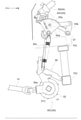
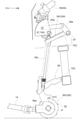
このように端部回転体部分50R,50Lが、低い位置に移行することができるのは、係合機構59による連動が解除され、リンク操作軸57との係合が解除された操作連動軸58,58が自由回転状態となるためである。つまり、アクチュエータ55の駆動で、リンク操作軸57とともに図9に仮想線で示す状態に持ち上げられていた端部吊り下げリンク機構54R,54Lが、リンク操作軸57との係合を解除されて、図9に実線で示す状態に、大きく垂れ下がる状態となることによる。
このように端部回転体部分50R,50Lが、低い位置に移行することができるのは、係合機構59による連動が解除され、リンク操作軸57との係合が解除された操作連動軸58,58が自由回転状態となるためである。つまり、アクチュエータ55の駆動で、リンク操作軸57とともに図9に仮想線で示す状態に持ち上げられていた端部吊り下げリンク機構54R,54Lが、リンク操作軸57との係合を解除されて、図9に実線で示す状態に、大きく垂れ下がる状態となることによる。
〔別実施形態〕
以下、別実施形態について説明する。下記の各別実施形態は、矛盾が生じない限り、複数組み合わせて用いてもよい。なお、本発明の範囲は、これら実施形態の内容に限定されるものではない。
以下、別実施形態について説明する。下記の各別実施形態は、矛盾が生じない限り、複数組み合わせて用いてもよい。なお、本発明の範囲は、これら実施形態の内容に限定されるものではない。
(1)上述した実施形態では、噛み合いクラッチ53の断接や、係合機構59の係脱が、折り畳み機構7による、中央フレーム70Cに対する右端部フレーム70R及び左端部フレーム70Lの、上下軸心y1,y2回りでの回動に伴って行われるように、噛み合いクラッチ53や、係合機構59の交合代を浅くしたものを例示したが、必ずしも、この構造に限られるものではなく、交合代を比較的深くして、端部回転軸51R,51Lや操作連動軸58,58を、人為操作で横外方へ引き出すことにより、噛み合いクラッチ53の断接や、係合機構59の係脱が行われるようにしてもよい。
その他の構成は、前述した実施形態と同様の構成を採用すればよい。
その他の構成は、前述した実施形態と同様の構成を採用すればよい。
(2)上述した実施形態では、中央駆動軸51C、及び端部回転軸51R,51Lを角軸で構成して、整地回転体52に回転動力を伝えるようにした構造の、中央回転体部分50C、及び端部回転体部分50R,50Lを示したが、必ずしもこの構造に限定されるものではない。
例えば、中央駆動軸51C、及び端部回転軸51R,51Lに、整地回転体52を直接に接着させたり、角軸以外の断面形状の軸を用いるなどしてもよい。
その他の構成は、前述した実施形態と同様の構成を採用すればよい。
例えば、中央駆動軸51C、及び端部回転軸51R,51Lに、整地回転体52を直接に接着させたり、角軸以外の断面形状の軸を用いるなどしてもよい。
その他の構成は、前述した実施形態と同様の構成を採用すればよい。
(3)上述した実施形態では、端部回転体部分50R,50Lが中央回転体部分50Cの下側へ潜り込む状態で折り畳まれる構造のものを例示したが、必ずしもこの構造に限定されるものではない。例えば、端部回転体部分50R,50Lが中央回転体部分50Cの上側へ乗り上がる状態で折り畳まれる構造のものであっても差し支えない。
その他の構成は、前述した実施形態と同様の構成を採用すればよい。
その他の構成は、前述した実施形態と同様の構成を採用すればよい。
(4)上述した実施形態では、昇降機構54の駆動源となるアクチュエータ55として、電動モータを採用した例を示したが、必ずしも、この構造に限定されるものではなく、例えば油圧シリンダや、電動シリンダ等を用いて構成されたものであってもよい。
その他の構成は、前述した実施形態と同様の構成を採用すればよい。
その他の構成は、前述した実施形態と同様の構成を採用すればよい。
(5)上述した実施形態では、折り畳みの際に、中央回転体部分50Cの位置を変えずに、端部回転体部分50R,50Lの位置を下げるようにした構造のものを例示したが、これに限られるものではない。例えば、端部回転体部分50R,50Lの位置を変えずに、中央回転体部分50Cの位置を上げる、もしくは下げるようにした構造のものであってもよい。
その他の構成は、前述した実施形態と同様の構成を採用すればよい。
その他の構成は、前述した実施形態と同様の構成を採用すればよい。
(6)上述した実施形態では、昇降機構54の駆動源となるアクチュエータ55を、中央回転体部分50Cの昇降を行う中央吊り下げリンク機構54Cに対して作用する箇所にのみ設けた例を示したが、必ずしもこの構造に限られるものではなく、例えば、端部回転体部分50R,50Lの昇降を行う端部吊り下げリンク機構54R,54Lに対して作用する箇所にも設けてもよい。
その他の構成は、前述した実施形態と同様の構成を採用すればよい。
その他の構成は、前述した実施形態と同様の構成を採用すればよい。
(7)上述した実施形態では、昇降機構54の駆動源となるアクチュエータ55として、電動モータを採用した例を示したが、必ずしも、この構造に限定されるものではなく、例えば油圧シリンダや、電動シリンダ等を用いて構成されたものであってもよい。
その他の構成は、前述した実施形態と同様の構成を採用すればよい。
その他の構成は、前述した実施形態と同様の構成を採用すればよい。
(8)上述した実施形態では、中央回転体部分50C、及び端部回転体部分50R,50Lが折り畳み機構7を介して苗植付装置6に支持された構造のものを例示したが、必ずしもこの構造に限定されるものではない。
例えば、図示はしないが、折り畳み機構7を介さずに、端部回転体部分50R,50Lが中央回転体部分50Cに対して分離可能に構成されたものであってもよい。
その他の構成は、前述した実施形態と同様の構成を採用すればよい。
例えば、図示はしないが、折り畳み機構7を介さずに、端部回転体部分50R,50Lが中央回転体部分50Cに対して分離可能に構成されたものであってもよい。
その他の構成は、前述した実施形態と同様の構成を採用すればよい。
本発明は、10条植え用の田植機に限定されず、10条未満の8条植え用の田植機や、10条よりも条数の多い田植機にも適用可能である。
1 走行機体
5 整地装置
6R,6L 苗植付ユニット
7 折り畳み機構
11 昇降リンク機構
50 整地用ロータ
50C 中央回転体部分
50R,50L 端部回転体部分
51C 中央駆動軸
51R,51L 端部回転軸
53 クラッチ機構
54C 吊り下げリンク機構
54R,54L 別の吊り下げリンク機構
55 アクチュエータ
60a 苗載置部
61 植付フレーム
62 苗植付機構
63 整地用フロート
70C 中央フレーム
70R 右端部フレーム
70L 左端部フレーム
y1 上下軸心
y2 上下軸心
y3,y4 上下軸心
x1 回転軸心
5 整地装置
6R,6L 苗植付ユニット
7 折り畳み機構
11 昇降リンク機構
50 整地用ロータ
50C 中央回転体部分
50R,50L 端部回転体部分
51C 中央駆動軸
51R,51L 端部回転軸
53 クラッチ機構
54C 吊り下げリンク機構
54R,54L 別の吊り下げリンク機構
55 アクチュエータ
60a 苗載置部
61 植付フレーム
62 苗植付機構
63 整地用フロート
70C 中央フレーム
70R 右端部フレーム
70L 左端部フレーム
y1 上下軸心
y2 上下軸心
y3,y4 上下軸心
x1 回転軸心
Claims (8)
- 走行機体の後方に昇降リンク機構を介して連結支持された苗植付装置と、
前記苗植付装置の前方において、左右横方向に沿う回転軸心周りで回転駆動される整地用ロータと、が配設され、
前記苗植付装置は、左右方向に沿って横一列に配置された複数の苗載置部と、前記苗載置部に対応して配置された複数の苗植付機構と、前記苗載置部及び前記苗植付機構を支持する植付フレームと、の組み合わせで構成される苗植付ユニットが、左右方向での右側と左側とに分割可能に備えられ、
前記苗植付ユニットが、前記昇降リンク機構に連結されており、
前記整地用ロータが、左右方向での中央部に位置する中央回転体部分と、その中央回転体部分の回転軸心に沿う方向で左右両側に配置される端部回転体部分とを備えて、前記中央回転体部分に対して左右の前記端部回転体部分を分割可能に構成され、
前記中央回転体部分が前記昇降リンク機構に支持され、左右の前記端部回転体部分が左右の対応する前記苗植付ユニットに支持されている水田作業機。 - 前記苗植付ユニットが、前記昇降リンク機構に対して折り畳み機構を介して連結されており、
前記折り畳み機構は、前記昇降リンク機構に支持された中央フレームと、その中央フレームの右端部に上下軸心回りで相対回動可能に連結された右端部フレームと、前記中央フレームの左端部に上下軸心回りで相対回動可能に連結された左端部フレームと、が備えられ、
前記右端部フレーム及び前記左端部フレームにおける前記中央フレームに連結された側とは反対側の端部に、右側の前記苗植付ユニット及び左側の前記苗植付ユニットにおける前記植付フレームが、前記中央フレームにおける左右の前記上下軸心と平行な上下軸心回りで相対揺動可能に支持されている請求項1記載の水田作業機。 - 前記中央回転体部分を支持する中央駆動軸と、左右の前記端部回転体部分を支持する端部回転軸と、が備えられ、前記端部回転軸が前記中央駆動軸に対して、係脱可能なクラッチ機構を介して、前記中央駆動軸に対する軸同士の連結を解除可能に連結され、
前記中央駆動軸が吊り下げリンク機構を介して昇降可能に前記中央フレームに支持され、左右の前記端部回転軸が、別の吊り下げリンク機構を介して昇降可能に左右の前記苗植付ユニットに支持され、
前記中央駆動軸に前記走行機体からの動力が入力されるとともに、前記中央駆動軸の吊り下げリンク機構を昇降作動させるアクチュエータが前記中央フレームに取り付けられている請求項2記載の水田作業機。 - 前記端部回転体部分は、前記クラッチ機構による軸同士の連結が解除された状態で、前記中央回転体部分よりも下方へ移動可能に構成されている請求項3記載の水田作業機。
- 前記苗植付ユニットが整地用フロートを備え、
前記端部回転体部分は、前記クラッチ機構による軸同士の連結が解除された状態で、前記整地用フロートよりも下方へ移動可能に構成されている請求項3又は4記載の水田作業機。 - 前記中央回転体部分は、前記クラッチ機構による軸同士の連結が解除された状態で、前記端部回転体部分よりも上方へ移動可能に構成されている請求項3記載の水田作業機。
- 前記クラッチ機構は、前記中央回転体部分に対する前記端部回転体部分の姿勢変更に伴って入り切り変更可能に構成され、
前記端部回転体部分の回転軸心が前記中央回転体部分の回転軸心に沿う姿勢でクラッチ入り状態となり、前記端部回転体部分の回転軸心が前記中央回転体部分の回転軸心から外れる方向への姿勢変更に伴って切り状態となるように構成されている請求項3~6のいずれか一項記載の水田作業機。 - 前記苗植付装置は、10条用の前記苗載置部を備えた10条植え用のものである請求項1~7のいずれか一項記載の水田作業機。
Priority Applications (1)
| Application Number | Priority Date | Filing Date | Title |
|---|---|---|---|
| CN202180040474.7A CN115697039B (zh) | 2020-07-14 | 2021-06-03 | 水田作业机 |
Applications Claiming Priority (2)
| Application Number | Priority Date | Filing Date | Title |
|---|---|---|---|
| JP2020120488A JP7442406B2 (ja) | 2020-07-14 | 2020-07-14 | 水田作業機 |
| JP2020-120488 | 2020-07-14 |
Publications (1)
| Publication Number | Publication Date |
|---|---|
| WO2022014187A1 true WO2022014187A1 (ja) | 2022-01-20 |
Family
ID=79555153
Family Applications (1)
| Application Number | Title | Priority Date | Filing Date |
|---|---|---|---|
| PCT/JP2021/021168 Ceased WO2022014187A1 (ja) | 2020-07-14 | 2021-06-03 | 水田作業機 |
Country Status (2)
| Country | Link |
|---|---|
| JP (1) | JP7442406B2 (ja) |
| WO (1) | WO2022014187A1 (ja) |
Citations (3)
| Publication number | Priority date | Publication date | Assignee | Title |
|---|---|---|---|---|
| JP2007228807A (ja) * | 2006-02-27 | 2007-09-13 | Iseki & Co Ltd | 苗移植機 |
| JP2008228600A (ja) * | 2007-03-17 | 2008-10-02 | Yanmar Co Ltd | 田植機 |
| JP2017035034A (ja) * | 2015-08-10 | 2017-02-16 | 株式会社クボタ | 水田作業機 |
-
2020
- 2020-07-14 JP JP2020120488A patent/JP7442406B2/ja active Active
-
2021
- 2021-06-03 WO PCT/JP2021/021168 patent/WO2022014187A1/ja not_active Ceased
Patent Citations (3)
| Publication number | Priority date | Publication date | Assignee | Title |
|---|---|---|---|---|
| JP2007228807A (ja) * | 2006-02-27 | 2007-09-13 | Iseki & Co Ltd | 苗移植機 |
| JP2008228600A (ja) * | 2007-03-17 | 2008-10-02 | Yanmar Co Ltd | 田植機 |
| JP2017035034A (ja) * | 2015-08-10 | 2017-02-16 | 株式会社クボタ | 水田作業機 |
Also Published As
| Publication number | Publication date |
|---|---|
| JP2022017756A (ja) | 2022-01-26 |
| JP7442406B2 (ja) | 2024-03-04 |
| CN115697039A (zh) | 2023-02-03 |
Similar Documents
| Publication | Publication Date | Title |
|---|---|---|
| KR101741606B1 (ko) | 이앙기 | |
| JP2013230094A (ja) | 歩行型田植機及び歩行型田植機のスタンド | |
| JP5221944B2 (ja) | 歩行型田植機 | |
| JP2011244718A (ja) | 作業機 | |
| JP6098627B2 (ja) | 苗移植機 | |
| WO2022014187A1 (ja) | 水田作業機 | |
| TWI584722B (zh) | Seedling transplant machine | |
| JP2016119879A5 (ja) | ||
| KR20150024775A (ko) | 모종 이식기 | |
| JP7033982B2 (ja) | 作業機 | |
| CN115697039B (zh) | 水田作业机 | |
| JP5825385B2 (ja) | 苗移植機 | |
| JP2008005743A (ja) | 苗植機 | |
| JP5765830B2 (ja) | 田植機 | |
| JP2013226107A (ja) | 苗移植機 | |
| JP7359190B2 (ja) | 乗用型苗植機 | |
| CN203575064U (zh) | 苗移植机 | |
| JP7034018B2 (ja) | 水田作業機 | |
| JP2014233269A (ja) | 苗移植機 | |
| JP6937726B2 (ja) | 水田作業機 | |
| CN213960731U (zh) | 秧苗移植机 | |
| JP6304414B2 (ja) | 苗移植機 | |
| JP7033983B2 (ja) | 作業機 | |
| JP2025019725A (ja) | 乗用型苗植機 | |
| JP3666492B2 (ja) | 苗植機 |
Legal Events
| Date | Code | Title | Description |
|---|---|---|---|
| 121 | Ep: the epo has been informed by wipo that ep was designated in this application |
Ref document number: 21842358 Country of ref document: EP Kind code of ref document: A1 |
|
| WWE | Wipo information: entry into national phase |
Ref document number: 202217070067 Country of ref document: IN |
|
| NENP | Non-entry into the national phase |
Ref country code: DE |
|
| 122 | Ep: pct application non-entry in european phase |
Ref document number: 21842358 Country of ref document: EP Kind code of ref document: A1 |