WO2022009291A1 - 波長クロスコネクト装置及び波長クロスコネクト方法 - Google Patents
波長クロスコネクト装置及び波長クロスコネクト方法 Download PDFInfo
- Publication number
- WO2022009291A1 WO2022009291A1 PCT/JP2020/026497 JP2020026497W WO2022009291A1 WO 2022009291 A1 WO2022009291 A1 WO 2022009291A1 JP 2020026497 W JP2020026497 W JP 2020026497W WO 2022009291 A1 WO2022009291 A1 WO 2022009291A1
- Authority
- WO
- WIPO (PCT)
- Prior art keywords
- band
- wavelength
- optical signal
- optical
- input
- Prior art date
- Legal status (The legal status is an assumption and is not a legal conclusion. Google has not performed a legal analysis and makes no representation as to the accuracy of the status listed.)
- Ceased
Links
Images



Classifications
-
- H—ELECTRICITY
- H04—ELECTRIC COMMUNICATION TECHNIQUE
- H04B—TRANSMISSION
- H04B10/00—Transmission systems employing electromagnetic waves other than radio-waves, e.g. infrared, visible or ultraviolet light, or employing corpuscular radiation, e.g. quantum communication
- H04B10/29—Repeaters
- H04B10/291—Repeaters in which processing or amplification is carried out without conversion of the main signal from optical form
-
- H—ELECTRICITY
- H04—ELECTRIC COMMUNICATION TECHNIQUE
- H04Q—SELECTING
- H04Q11/00—Selecting arrangements for multiplex systems
- H04Q11/0001—Selecting arrangements for multiplex systems using optical switching
- H04Q11/0005—Switch and router aspects
-
- H—ELECTRICITY
- H04—ELECTRIC COMMUNICATION TECHNIQUE
- H04J—MULTIPLEX COMMUNICATION
- H04J14/00—Optical multiplex systems
- H04J14/02—Wavelength-division multiplex systems
- H04J14/0201—Add-and-drop multiplexing
- H04J14/0202—Arrangements therefor
- H04J14/021—Reconfigurable arrangements, e.g. reconfigurable optical add/drop multiplexers [ROADM] or tunable optical add/drop multiplexers [TOADM]
- H04J14/0212—Reconfigurable arrangements, e.g. reconfigurable optical add/drop multiplexers [ROADM] or tunable optical add/drop multiplexers [TOADM] using optical switches or wavelength selective switches [WSS]
-
- H—ELECTRICITY
- H04—ELECTRIC COMMUNICATION TECHNIQUE
- H04J—MULTIPLEX COMMUNICATION
- H04J14/00—Optical multiplex systems
- H04J14/02—Wavelength-division multiplex systems
- H04J14/0201—Add-and-drop multiplexing
- H04J14/0215—Architecture aspects
- H04J14/0217—Multi-degree architectures, e.g. having a connection degree greater than two
-
- H—ELECTRICITY
- H04—ELECTRIC COMMUNICATION TECHNIQUE
- H04J—MULTIPLEX COMMUNICATION
- H04J14/00—Optical multiplex systems
- H04J14/02—Wavelength-division multiplex systems
-
- H—ELECTRICITY
- H04—ELECTRIC COMMUNICATION TECHNIQUE
- H04J—MULTIPLEX COMMUNICATION
- H04J14/00—Optical multiplex systems
- H04J14/02—Wavelength-division multiplex systems
- H04J14/0201—Add-and-drop multiplexing
- H04J14/0202—Arrangements therefor
- H04J14/0213—Groups of channels or wave bands arrangements
-
- H—ELECTRICITY
- H04—ELECTRIC COMMUNICATION TECHNIQUE
- H04Q—SELECTING
- H04Q11/00—Selecting arrangements for multiplex systems
- H04Q11/0001—Selecting arrangements for multiplex systems using optical switching
-
- H—ELECTRICITY
- H04—ELECTRIC COMMUNICATION TECHNIQUE
- H04Q—SELECTING
- H04Q11/00—Selecting arrangements for multiplex systems
- H04Q11/0001—Selecting arrangements for multiplex systems using optical switching
- H04Q11/0005—Switch and router aspects
- H04Q2011/0007—Construction
- H04Q2011/0011—Construction using wavelength conversion
-
- H—ELECTRICITY
- H04—ELECTRIC COMMUNICATION TECHNIQUE
- H04Q—SELECTING
- H04Q11/00—Selecting arrangements for multiplex systems
- H04Q11/0001—Selecting arrangements for multiplex systems using optical switching
- H04Q11/0005—Switch and router aspects
- H04Q2011/0007—Construction
- H04Q2011/0015—Construction using splitting combining
-
- H—ELECTRICITY
- H04—ELECTRIC COMMUNICATION TECHNIQUE
- H04Q—SELECTING
- H04Q11/00—Selecting arrangements for multiplex systems
- H04Q11/0001—Selecting arrangements for multiplex systems using optical switching
- H04Q11/0005—Switch and router aspects
- H04Q2011/0007—Construction
- H04Q2011/0016—Construction using wavelength multiplexing or demultiplexing
-
- H—ELECTRICITY
- H04—ELECTRIC COMMUNICATION TECHNIQUE
- H04Q—SELECTING
- H04Q11/00—Selecting arrangements for multiplex systems
- H04Q11/0001—Selecting arrangements for multiplex systems using optical switching
- H04Q11/0005—Switch and router aspects
- H04Q2011/0037—Operation
- H04Q2011/0049—Crosstalk reduction; Noise; Power budget
Definitions
- the present invention relates to a wavelength cross-connect device and a wavelength cross-connect method used for multi-band transmission in which wavelength-multiplexed signal light obtained by multiplexing each optical signal of a plurality of different wavelength bands is transmitted by an optical fiber.
- the wavelength cross-connect device used in a multi-band transmission system is an optical transmission path composed of one or a plurality of optical fibers for transmitting wavelength division multiplexing signal light obtained by multiplexing each optical signal in a plurality of different wavelength bands. On the other hand, it is an optical node connected between arbitrary directions in the optical network.
- wavelength cross-connect device wavelength division multiplexing signal light transmitted from the input side route is output to the output side route via a plurality of WSS (Wavelength Selective Switch).
- WSS Widelength Selective Switch
- FIG. 6 shows the configuration of the wavelength cross-connect device 20 used in the conventional multi-band transmission system (also referred to as a system) 10.
- the system 10 has M wavelength band demultiplexers (also referred to as demultiplexers) 11a, 11b, ..., 11m connected for each of the M lines indicated by the code Mi on the input side, and the code Mo on the output side. It is provided with M wavelength band combiners (also referred to as combiners) 12a, 12b, ..., 12m connected for each of the M directions shown by. Further, the system 10 has an S-band WXC (Wavelength Cross Connect) unit 21 and a C-band WXC connected by an optical fiber between the demultiplexer 11a to 11m and the duplexer 12a to 12m. A wavelength cross-connect device 20 having a unit 22 and an L-band WXC unit 23 is provided. The S-band WXC unit 21, the C-band WXC unit 22, and the L-band WXC unit 23 are also referred to as WXC units 21 to 23.
- M wavelength band demultiplexers also referred to as demultiplexers
- M wavelength band combiners also referred to as
- each WXC unit 21 to 23 has M optical amplifiers 24a, 24b, ..., 24m and M WSS25a, 25b, ..., On the input side. It has 25m. Each WSS 25a-25m has one input end and an M output end (1 ⁇ M). Further, the L band WXC unit 23 has M WSS26a, 26b, ..., 26m and M optical amplifiers 27a, 27b, ..., Which have an M input end and one output end (M ⁇ 1) on the output side. It has 27m. Each element of these optical amplifiers 24a to 24m, WSS25a to 25m, WSS26a to 26m, and optical amplifiers 27a to 27m is connected by an optical fiber or an optical waveguide.
- the wavelength division multiplexing signal light 1a, 1b, ..., 1m transmitted in multiple bands for each of the M lines on the input side is input to the demultiplexers 11a to 11m as follows. That is, the wavelength division multiplexing signal light 1a is input to the demultiplexer 11a, the wavelength division multiplexing signal light 1ba is input to the demultiplexer 11b, and the wavelength division multiplexing signal light 1m is input to the demultiplexer 11m.
- each of the wavelength division multiplexing signal lights 1a to 1m is a multiplexing of each optical signal of the S band, C band, and L band of the wavelength band described later.
- Each wavelength band is an S band of 1460 nm to 1530 nm, a C band of 1530 nm to 1565 nm, and an L band of 1565 nm to 1625 nm in order from the short wavelength side.
- Each of the S band, C band, and L band optical signals is assigned to the S band, C band, and L band of the optical fiber as a route at the time of transmission.
- the demultiplexer 11a demultiplexes the wavelength division multiplexing signal light 1a into S-band, C-band, and L-band optical signals, and outputs the light to the optical amplifiers 24a of the WXC units 21 to 23. That is, the demultiplexer 11a outputs the demultiplexed S band optical signal to the optical amplifier 24a of the S band WXC unit 21, outputs the C band optical signal to the optical amplifier 24a of the C band WXC unit 22, and outputs the L band. The optical signal is output to the optical amplifier 24a of the L band WXC unit 23.
- the wavelength division multiplexing signal light 1b to 1 m is demultiplexed into the S band, C band, and L band optical signals in the same manner as in the demultiplexer 11a, and each WXC unit 21 to It outputs to 23 optical amplifiers 24b to 24m.
- the optical amplifiers 24a to 24m of each WXC unit 21 to 23 amplify each optical signal of S band, C band and L band and output to WSS 25a to 25m of each WXC unit 21 to 23.
- Each WSS 25a to 25m has a function of selecting an optical signal for each wavelength band and adjusting an attenuation amount.
- the M output ends every WSS25a to 25m are connected to the M input ends of WSS26a to 26m on the output side.
- the WSS25a outputs an L-band optical signal from the first output end described at the top to the second input end of the WSS26a on the output side, and outputs an L-band optical signal from the second output end to the output side. It is output to the input end of the WSS, and the L band optical signal is output from the third output end to the first input end of the WSS 26m on the output side. In this way, the L band optical signal is output from each output end of one WSS25a to the input ends of different WSS26a to 26m.
- Each of WSS26a to 26m on the output side sequentially selects optical signals of a plurality of wavelength bands input from M input ends and outputs them from one output end to the optical amplifiers 27a to 27m.
- each optical amplifier 27a to 27m The output ends of each optical amplifier 27a to 27m are connected to the combiner 12a to 12m.
- the optical amplifiers 27a to 27m amplify each of the S band, C band, and L band optical signals and then output them to the corresponding combiner 12a to 12m.
- each of the combiners 12a to 12m combines the S-band, C-band, and L-band optical signals amplified by the optical amplifiers 27a to 27m of the WXC units 21 to 23.
- the wavelength division multiplexing signal light due to this combined wave is multiband transmitted to M directions Mo.
- Non-Patent Document 1 As a conventional technique relating to such a wavelength cross-connect device 20, there is one described in Non-Patent Document 1.
- the wavelength cross-connect device 20 described above supports multi-band transmission, and the S-band WXC unit 21 and C-band corresponding to the S-band, C-band, and L-band optical signals demultiplexed by the demultiplexer 11a. It is necessary to provide the WXC unit 22 and the L band WXC unit 23. For this reason, the scale of the device and the power consumption are each tripled or more as compared with the wavelength cross-connect device corresponding to a single band.
- each WXC unit 21 to 23 since there is a difference in optical characteristics due to the difference in wavelength band of S band, C band and L band, the transmission performance of each optical signal of S band, C band and L band is improved. There will be a difference. For example, the wavelength band dependence of the transmission band and the light loss in the WSS or the optical amplifier occurs.
- the technical readiness level of the components used for the optical device differs depending on the wavelength band. If the technology maturity period for improving optical components required to ensure a certain level of optical performance (passband, optical loss, etc.) differs depending on the wavelength band, the optical device in the wavelength band that requires the most technology maturity period. With the maturity of the technology, the realization time of multi-band compatible WXC will be rate-determined. For example, the technological maturity level of optical devices is highest in the C band, which is most often applied to general optical transmission systems, and is lowest in the order of the L band and the S band. For this reason, there is a problem that the realization time of the multi-band compatible WXC is rate-determined by the realization of the S-band optical device that requires a technology readiness level.
- the present invention has been made in view of such circumstances, and can reduce the scale and power consumption of the device, eliminate the difference in the transmission performance of each optical signal due to the different wavelength bands of WXC, and the wavelength that requires the most technological maturity period. It is an object to avoid that the realization time of the multi-band compatible WXC is rate-determined by the optical device of the band.
- the present invention is a wavelength cross-connect device, wherein the wavelength cross-connect device is a different plurality of different devices that have been multiband-transmitted in an optical transmission line composed of one or a plurality of optical fibers.
- Wavelength-multiplexed signal light which is a multiplexing of each optical signal in the wavelength band of A contention WSS (Wavelength Selective Switch) having an output end of the above is used for relay processing to change the direction and output to the direction of the output side.
- a contention WSS Wivelength Selective Switch
- a WXC (Wavelength Cross Connect) unit that performs the relay processing of the optical signal of a predetermined specific wavelength band is provided, and an optical signal of a wavelength band other than the specific wavelength band is provided on the input side of the WXC unit.
- An input side conversion unit that converts an optical signal in the specific wavelength band is provided, and an optical signal in the specific wavelength band converted by the input side conversion unit is converted into an optical signal before conversion on the output side of the WXC unit.
- An output-side conversion unit is provided, and an optical signal of the specific wavelength band directly input from the input side is directly output after relay processing by the WXC unit.
- the scale and power consumption of the device can be reduced, the difference in the transmission performance of each optical signal due to different wavelength bands of WXC is eliminated, and the optical device of the wavelength band that requires the most technological maturity period can be used for multi-band compatible WXC. It is possible to avoid the realization time being rate-determined.
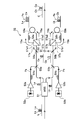
- FIG. 1 is a block diagram showing a configuration of a multi-band transmission system using the wavelength cross-connect device according to the embodiment of the present invention.
- the wavelength cross-connect device 20A applied to the multi-band transmission system 10A of the embodiment shown in FIG. 1 differs from the conventional wavelength cross-connect device 20 (FIG. 6) in that the demultiplexers 11a to 11m and the combiner 12a. Between ⁇ 12m, S / C conversion unit 31 and L / C conversion unit 32 on the input side, optical amplifiers 24a to 24m, one WXC unit 22A, optical amplifiers 27a to 27m on the output side, and C / It is configured to include an S conversion unit 35 and a C / L conversion unit 36.
- the WXC unit 22A handles the wavelength of the C band, which is the wavelength band (referred to as a specific wavelength band) having the highest technological maturity of the above-mentioned WXC component.
- the WXC unit 22A has m sets of optical amplifiers 24a, 24b, ..., 24m having three on the input side, and m W ⁇ W (M-1) contention WSS (also referred to as WSS) 25aA. , 25bA, ..., 25mA.
- m W (M-1) ⁇ W contention WSS26aA, 26bA, ..., 26mA and M sets of optical amplifiers 27a, 27b, ..., 27m in which three are set are provided. ..
- W is the number of wavelength bands, and in this example, it is the number of three wavelength bands of S band, C band and L band.
- M is the number of directions at one end of each WSS25aA to 25mA and each WSS26aA to 26mA at the input end or the output end.
- the number of routes is at least two at one end, so that the number is set to two in this example.
- the input ends and output ends of WSS25aA to 25mA and 26aA to 26mA are defined as the first input end, the second input end, the third input end, the first output end, the second output end, and the third output end from the top. ..
- the first output end of WSS25aA on the input side is connected to the first input end of WSS26bA and WSS26mA on the output side.
- the second output end of WSS25aA on the input side is connected to the second input end of WSS26bA and WSS26mA on the output side.
- the third output end of WSS25aA on the input side is connected to the third input end of WSS26bA and WSS26mA on the output side.
- the first input end of, for example, WSS26bA on the output side is connected to the first output end of WSS25aA and WSS25mA on the input side. That is, the demultiplexers 11a to 11m are connected so that two optical signals in the same wavelength band after demultiplexing are input to the first input terminal of WSS26bA on the output side. Similarly, the other WSS25bA to 25mA and WSS26bA to 26mA are also connected as shown by the connection line in the drawing.
- the contention WSS has a plurality of input ends and a plurality of output ends, and has a function of selecting an optical signal for each wavelength band and adjusting an attenuation amount. Further, as described above, the contention WSS is characterized by having a processing function of a plurality of inputs ⁇ W or W (M-1) ⁇ and a plurality of outputs ⁇ W (M-1) or W ⁇ of an optical signal.
- the contention WSS is characterized by having a processing function of a plurality of inputs ⁇ W or W (M-1) ⁇ and a plurality of outputs ⁇ W (M-1) or W ⁇ of an optical signal.
- collision (contention) of the optical signals occurs. Therefore, it is set so that contention does not occur.
- a C-band optical signal having 96 wavelengths with wavelength division multiplexing of wavelengths ⁇ 1 to ⁇ 96 is input to the three first to third input ends, but the same wavelength is not input to the three input ends at the same time. It is set as. In other words, the three input terminals are set so that optical signals of the C band having different wavelengths are simultaneously input. For example, an optical signal having a wavelength ⁇ 1 in the C band is input to the first input end of WSS25aA, an optical signal having a wavelength ⁇ 2 in the C band is input to the second input end, and a wavelength in the C band is input to the third input end. It is set so that the optical signal of the C band of ⁇ 3 is input.
- the wavelength division multiplexing signal light 1a, 1b, ..., 1m transmitted in multiple bands for each of the M lines on the input side is in the S band, C band, and L band in each demultiplexer 11a to 11m. It is split into optical signals.
- the demultiplexed S band optical signal is input to WSS26aA to 26mA via the S / C conversion unit 31 and the optical amplifiers 24a to 24m described later.
- the demultiplexed C-band optical signal is input to WSS26aA to 26mA via optical amplifiers 24a to 24m.
- the demultiplexed L band optical signal is input to WSS26aA to 26mA via the L / C conversion unit 32 and the optical amplifiers 24a to 24m described later.
- the S / C conversion unit 31 converts the S band light signal into a C band light signal
- the L / C conversion unit 32 converts the L band light signal into a C band light signal.
- the S / C conversion unit 31 and the L / C conversion unit 32 form the input-side conversion unit according to the claim.
- connection configuration between each output end of the duplexer 11a to 11m and the input end of the WXC unit 22A is as follows. That is, the output end at which the wavelength division multiplexing signal light 1a of the S band, C band, and L band transmitted in multiband from the input side path outputs the S band optical signal demultiplexed by the demultiplexer 11a is S / It is connected to the optical amplifier 24a of the WXC unit 22A via the C conversion unit 31. Further, the output end of the C-band optical signal of the duplexer 11a is directly connected to the input end of the optical amplifier 24a of the WXC unit 22A. Further, the output end of the L band optical signal of the demultiplexer 11a is connected to the input end of the optical amplifier 24a of the WXC unit 22A via the L / C conversion unit 32.
- the output end of the wavelength division multiplexing signal light 1b from the input side path to output the S band optical signal demultiplexed by the demultiplexer 11b is the optical amplifier 24b of the WXC unit 22A via the S / C conversion unit 31. It is connected to the. Further, the output end of the C-band optical signal of the duplexer 11a is directly connected to the input end of the optical amplifier 24b of the WXC unit 22A. Further, the output end of the L band optical signal of the demultiplexer 11a is connected to the input end of the optical amplifier 24a of the WXC unit 22A via the L / C conversion unit 32.
- the output end of the wavelength division multiplexing signal light 1 m from the input side path to output the S band optical signal demultiplexed by the demultiplexer 11 m is the optical amplifier 24 m of the WXC unit 22A via the S / C conversion unit 31. It is connected to the. Further, the output end of the C-band optical signal of the duplexer 11a is directly connected to the input end of the optical amplifier 24m of the WXC unit 22A. Further, the output end of the L band optical signal of the demultiplexer 11a is connected to the input end of the optical amplifier 24m of the WXC unit 22A via the L / C conversion unit 32.
- the C / S conversion unit 35 connected to the optical amplifiers 27a to 27m on the output side of the WXC unit 22A converts the C band optical signal into which the S band optical signal is converted by the S / C conversion unit 31 on the input side. , Converted to S-band optical signal.
- the C / L conversion unit 36 connected to the optical amplifiers 27a to 27m converts the C-band optical signal converted by the L / C conversion unit 32 on the input side into an L-band optical signal.
- a C / L conversion unit 36 is provided.
- the C / S conversion unit 35 and the C / L conversion unit 36 constitute the output-side conversion unit according to claim.
- the output end for outputting the C band optical signal directly input from the input end is directly connected to the input end of the combiner 12a to 12m.
- FIG. 2 shows the circuit configuration of the L / C conversion unit 32 as a representative, and a description thereof will be given.
- the L / C conversion unit 32 shown in FIG. 2 includes a WSS 51, wavelength variable light sources 52a, 52b, amplifiers 53a, 53b, polarization controllers 54a, 54b, and WDM (Wavelength Division Multiplexing) couplers 55a, 55b, 56a, It is configured to include a 56b, a polarization beam splitters 57a and 57b, a polarization controller 58a and 58b, a loop-shaped highly nonlinear fiber 59a and 59b, and an optical coupler 60.
- WSS 51 wavelength variable light sources 52a, 52b, amplifiers 53a, 53b, polarization controllers 54a, 54b, and WDM (Wavelength Division Multiplexing) couplers 55a, 55b, 56a
- WDM Widelength Division Multiplexing
- a indicates a component on the long wavelength side of the optical signal
- b indicates a component on the short wavelength side of the optical signal
- the polarization beam splitter 57a connects two input / output ports 57a1 and 57a2 in a loop shape with an optical fiber, and a loop-shaped high non-linear fiber 59a is connected in the middle of the optical fiber. Further, a polarization controller 58a is connected between one input / output port 57a1 of the polarization beam splitter 57a and the highly non-linear fiber 59a.
- two input / output ports 57b1 and 57b2 are connected by an optical fiber in a loop shape, and a loop-shaped high nonlinear fiber 59b is connected in the middle of the optical fiber.
- a polarization controller 58b is connected between one input / output port 57b1 of the polarization beam splitter 57b and the highly nonlinear fiber 59b.
- the pump light output from the wavelength-variable light source 52a is amplified by the amplifier 53a, and the pump light Pa whose polarization is controlled by the polarization controller 54a is input to the polarization beam splitter 57a via the WDM couplers 55a and 56a.
- the pump light Pa is input to the polarization beam splitter 57a in a linearly polarized state tilted by 45 degrees with respect to the main axis of the polarization beam splitter 57a.
- the tilt of 45 degrees is realized by the polarization control of the polarization controller 54a.
- the pump light output from the wavelength variable light source 52b is amplified by the amplifier 53b, and the pump light Pb whose polarization is controlled by the polarization controller 54b is input to the polarization beam splitter 57b via the WDM couplers 55b and 56b. ..
- the pump light Pb is input to the polarization beam splitter 57b in a linearly polarized state tilted by 45 degrees with respect to the main axis of the polarization beam splitter 57b.
- the tilt of 45 degrees is realized by the polarization control of the polarization controller 54b.
- the L band optical signal (also referred to as optical signal L) is input from the demultiplexer 11a shown in FIG. 1 to the WSS 51 shown in FIG. 2 of the L / C conversion unit 32.
- this optical signal L an optical signal of the long wavelength side La (also referred to as a long wavelength side optical signal La) and an optical signal of the short wavelength side Lb (also referred to as a short wavelength side optical signal Lb) are combined.
- the WSS 51 divides the optical signal L into a long wavelength side optical signal La and a short wavelength side optical signal Lb and outputs the optical signal L.
- This long wavelength side optical signal La is input to the polarization beam splitter 57a via the WDM couplers 55a and 56a.
- the short wavelength side optical signal Lb is input to the polarization beam splitter 57b via the WDM couplers 55b and 56b.
- the long wavelength side optical signal La and the pump light Pa input to the polarization beam splitter 57a are output from the first input / output port 57a1 of the polarization beam splitter 57a, and are indicated by the arrow Y5a. As shown, it follows a loop path input to the second input / output port 57a2 via the polarization controller 58a and the highly nonlinear fiber 59a.
- the long wavelength side optical signal La and the pump optical Pa output from the first input / output port 57a1 of the polarization beam splitter 57a are controlled by the polarization controller 58a and are controlled by the highly nonlinear fiber 59a.
- the highly non-linear fiber 59a is an optical fiber having a high non-linear constant as a parameter, and efficiently causes four-wave mixing in a loop to perform wavelength band conversion.
- the highly non-linear fiber 59a is a new one wavelength band by interacting two wavelength bands of the long wavelength side optical signal La and the pump light Pa as a non-linear optical intermodulation phenomenon by the four-wave mixing process.
- An optical signal Ca on the long wavelength side of the C band is generated.
- the generated optical signal Ca, the long wavelength side optical signal La, and the pump optical Pa are input to the second input / output port 57a2 of the polarization beam splitter 57a.
- the long wavelength side optical signal La and the pump optical Pa input to the polarization beam splitter 57a are output from the second input / output port 57a2 and are high as shown by the arrow Y6a in the direction opposite to the arrow Y5a. It follows a loop path input to the first input / output port 57a1 via the non-linear fiber 59a and the polarization controller 58a. In this loop path as well, a new optical signal (also referred to as a long wavelength side optical signal Ca) of the C band long wavelength side Ca is newly generated by the four-wave mixing process.
- a new optical signal also referred to as a long wavelength side optical signal Ca
- the two long wavelength side optical signals Ca generated by following the loop path in both directions are wavelength-multiplexed by the polarization beam splitter 57a. As shown by the arrow Y7a, this long wavelength side optical signal Ca is output toward the input side, extracted by the WDM coupler 56a, and output to the optical coupler 60.
- the same wavelength band conversion process as on the long wavelength side is performed. That is, the long wavelength side optical signal Lb and the pump light Pb input to the polarization beam splitter 57b are output from the first input / output port 57b1 of the polarization beam splitter 57b, and as shown by the arrow Y5b, the polarization controller 58b. And follow the loop path input to the second input / output port 57b2 via the highly non-linear fiber 59b.
- the long wavelength side optical signal Lb and the pump light Pb output from the first input / output port 57b1 are subjected to four-wave mixing processing by the highly nonlinear fiber 59b while the polarization is controlled by the polarization controller 58b. ..
- a new optical signal Cb on the short wavelength side of the C band is newly generated, and is input to the second input / output port 57b2 of the polarization beam splitter 57b together with the long wavelength side optical signal Lb and the pump light Pb.
- the long wavelength side optical signal Lb and the pump light Pb follow the loop path indicated by the arrow Y6b in the direction opposite to the arrow Y5b from the second input / output port 57b2 of the polarization beam splitter 57b.
- a new optical signal on the short wavelength side Cb in the C band (also referred to as a short wavelength side optical signal Cb) is newly generated by the four-wave mixing process in the same manner as described above.
- the two short wavelength side optical signals Cb generated by following the loop path in both directions are wavelength-multiplexed by the polarization beam splitter 57b, output to the input side indicated by the arrow Y7b, and are optical couplers via the WDM coupler 56b. It is output to 60.
- the optical coupler 60 combines the long wavelength side optical signal Ca and the short wavelength side optical signal Cb to form a C band optical signal.
- the L / C conversion unit 32 converts the L-band optical signal from the demultiplexer 11a into a C-band optical signal. This converted C-band optical signal is input to the optical amplifier 24a of the WXC unit 22A.
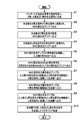
- step S1 shown in FIG. 3 the wavelength division multiplexing signal light 1a to 1m transmitted in multiband from the input side direction Mi shown in FIG. 1 is every wavelength division multiplexing signal light 1a to 1m in each demultiplexer 11a to 11m. In addition, it is demultiplexed into S-band, C-band, and L-band optical signals.
- step S2 the demultiplexed S-band optical signal is converted into a C-band optical signal by each S / C conversion unit 31 and output to the optical amplifiers 24a to 24m of the WXC unit 22A.
- step S3 the demultiplexed C-band optical signal is directly output to the optical amplifiers 24a to 24m.
- step S4 the demultiplexed L-band optical signal is converted into a C-band optical signal by each L / C conversion unit 32 and output to the optical amplifiers 24b to 24m.
- the processes of steps S2 to S4 may be executed in any order.
- step S5 each optical amplifier 24a to 24m amplifies the C band optical signal and outputs it to each WSS 25aA to 25mA.
- each WSS25aA to 25mA on the input side of the WXC unit 22A outputs the input C band optical signal to the optical amplifiers 27a to 27m via a predetermined predetermined output side WSS26aA to 26mA.
- each optical amplifier 27a to 27m on the output side of the WXC unit 22A amplifies the C band optical signal converted by the S / C conversion unit 31 on the input side and outputs it to the C / S conversion unit 35.
- the C / S conversion unit 35 converts the C-band optical signal converted on the input side into an S-band optical signal and outputs it to the combiner 12a to 12m.
- each optical amplifier 27a to 27m directly amplifies the C band optical signal input to the WXC unit 22A from the demultiplexer 11a to 11m, and directly outputs the C band optical signal to each combiner 12a to 12m.
- each optical amplifier 27a to 27m on the output side of the WXC unit 22A amplifies the C band optical signal converted by the L / C conversion unit 32 on the input side and outputs it to the C / L conversion unit 36.
- the C / L conversion unit 36 converts the C-band optical signal converted on the input side into an L-band optical signal and outputs it to the combiner 12a to 12m.
- the processes in steps S7 to S9 may be executed in any order.
- each of the combiners 12a to 12m combine the input S-band, C-band, and L-band optical signals and transmit them in multi-band to the M direction Mo on the output side.
- the wavelength multiplex signal light 1a to 1m transmitted in a multi-band from a plurality of route Mi in which one or a plurality of optical fibers are bundled in one route Mi is a route.
- the direction is changed by WSS to the output side direction Mo. Performs relay processing to output.
- the wavelength cross-connect device 20A has optical amplifiers 24a to 24m, 27a to 27m, and a contention WSS25aA to 25mA, 26aA to 26mA having a plurality of input ends and a plurality of output ends, and among different wavelength bands, A WXC unit 22A that performs relay processing of an optical signal in a predetermined specific wavelength band (C band) is provided. Further, on the input side of the WXC unit 22A, an input side conversion unit (S / C conversion unit 31 and L / C conversion unit 32) that converts an optical signal in a wavelength band other than the specific wavelength band into an optical signal in a specific wavelength band.
- S / C conversion unit 31 and L / C conversion unit 32 an input side conversion unit that converts an optical signal in a wavelength band other than the specific wavelength band into an optical signal in a specific wavelength band.
- an output side conversion unit (C / S conversion unit 35 and C) that converts an optical signal of a specific wavelength band converted by the input side conversion unit into an optical signal before the conversion.
- the / L conversion unit 36 is provided on the output side of the WXC unit 22A.
- one WXC unit 22A for relay processing an optical signal in a specific wavelength band is provided.
- An optical signal in a wavelength band other than the specific wavelength band on the input side is converted into an optical signal in the specific wavelength band by the input side conversion unit and input to the WXC unit 22A.
- the optical signal of the specific wavelength band on the input side is directly input to the WXC unit 22A.
- the plurality of optical signals of a specific wavelength band input to the WXC unit 22A are input from a plurality of input ends of the contention WSS25aA to 25mA on the input side, and are input from the plurality of output ends of the contention WSS26aA to 26mA on the output side. Output to multiple input ends.
- the WXC unit 22A performs relay processing with an optical signal in a specific wavelength band which is the same wavelength band.
- the output side conversion unit converts it to the optical signal before the conversion.
- the optical signal of the specific wavelength band directly input from the input side is directly output after the relay processing by the WXC unit 22A.
- the WXC unit 22A has a function of processing optical signals in the same wavelength band (specific wavelength band), the difference in optical characteristics due to the difference in the wavelength band of multi-band transmission as in the conventional case is eliminated.
- each WXC unit 21 to 23 corresponds to optical signal processing in different wavelength bands, but in the present invention, one WXC unit 22A performs optical signal processing in the same wavelength band (specific wavelength band). Can be done. Therefore, the device scale and power consumption of the WXC unit 22A can be reduced.
- optical signals of the same wavelength band are input and output. Therefore, in the wavelength band that lowers the technical maturity of the components (WSS25aA to 25mA, 26aA to 26mA and the optical amplifiers 24b to 24m, 27a to 27m) in each WXC unit 21 to 23 (FIG. 6) as in the conventional case.
- the S-band WXC unit 21 (FIG. 6) can eliminate the limitation of the transmission performance of the other WXC units 22 and 23. That is, it is possible to avoid that the realization time of the multi-band compatible WXC is rate-determined by the optical device in the wavelength band (S band) that requires the most technological maturity period.
- the specific wavelength band is a wavelength band (C band) that maximizes the technology readiness level among the wavelength bands that differ in the technology readiness level of the components related to the transmission performance of the WXC unit 22A.
- the WXC unit 22A since the WXC unit 22A has components related to a specific wavelength band that maximizes the technology readiness level, the WXC unit 22A can have the highest transmission performance.
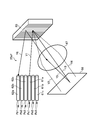
- the input collimator 61 is connected to an optical fiber (not shown) on the input side.
- an optical signal in the C band from the optical fiber is incident on the grating 65 from the first input end Pa1 via the collimator 61a as shown by the arrow Y1.
- the grating 65 diffracts and reflects an optical signal at different angles depending on the wavelength, thereby performing demultiplexing (for example, 3 demultiplexing) as shown by arrows Y2, Y3, and Y4.
- demultiplexing for example, 3 demultiplexing
- the optical switching element 68 reflects the optical signal divided into three. This reflection is incident on the collimator 62a for a desired output via the lens 67 and the grating 65 and is output from the output end Pb1 of the collimator 62a, as shown by the arrow Y5 as a representative of one optical signal. .. In other words, it is output from the output end of WSS25aA on the input side to the first input end of WSS26bA, 26mA on the output side.
- the optical switching element 68 has a wavelength such that the reflected optical signal is directed to the first output end Pb1 of the WSS25aA on the input side connected to Pa1 at the first input end of WSS26bA, 26mA (FIG. 1) on the output side.
- the reflection angle is changed each time to reflect the optical signal (arrow Y5).
- the optical signal reflected by the grating 65 can be incident on the desired output collimator 62a. This is because the reflection angle of the optical signal at the grating 65 is changed by changing the reflection angle of the optical switching element 68, and this processing makes it possible to enter the collimator 62a for a desired output.
- the WSS25aA can be composed of an optical system component that is a combination of a plurality of collimators 61a to 61c, 62a to 62c, a grating 65, a lens 67, and an optical switching element 68, and a plurality of optical system components can be combined.
- WSS25aA to 25mA or WSS26aA to 26mA can be configured. Therefore, since a plurality of WSS25aA to 25mA or WSS26aA to 26mA can be integrated, the wavelength cross-connect device 20A can be downsized.
- a WSS having a configuration of a plurality of outputs Pb1 to Pb4 with one input Pa1 exists as a general-purpose type based on maturity technology.
- this WSS it is possible to easily create a contention WSS having the configuration shown in FIG.
- a wavelength cross-connect device wherein the wavelength cross-connect device transmits each optical signal of a plurality of different wavelength bands transmitted in multiple bands by an optical transmission line composed of one or a plurality of optical fibers. Multiplexed wavelengths Multiplexed signal light is divided into different wavelength bands for each direction. After amplifying the optical signal of each wavelength band with an optical amplifier, a contention WSS having a plurality of input ends and a plurality of output ends. (Wavelength Selective Switch) is used to perform relay processing to change the direction and output to the output side, and has the optical amplifier and the contention WSS, and is specified in advance within the different wavelength bands.
- WSS Wavelength Selective Switch
- a WXC (Wavelength Cross Connect) unit that performs the relay processing of the optical signal in the wavelength band is provided, and an optical signal in a wavelength band other than the specific wavelength band is converted into an optical signal in the specific wavelength band on the input side of the WXC unit.
- An input-side conversion unit for conversion is provided, and an output-side conversion unit that converts an optical signal of a specific wavelength band converted by the input-side conversion unit into an optical signal before conversion is provided on the output side of the WXC unit.
- the wavelength cross-connect device is characterized in that the optical signal of the specific wavelength band directly input from the input side is directly output after the relay processing in the WXC unit.
- one WXC unit for relay processing an optical signal in a specific wavelength band is provided.
- An optical signal in a wavelength band other than the specific wavelength band on the input side is converted into an optical signal in the specific wavelength band by the input side conversion unit and input to the WXC unit.
- the optical signal of the specific wavelength band on the input side is directly input to the WXC unit.
- the optical signals of a plurality of specific wavelength bands input to the WXC unit are input from the plurality of input ends of the contention WSS on the input side, and are input from the plurality of output ends to the plurality of input ends of the contention WSS on the output side. It is output. Further, it is output from a plurality of output ends of the contention WSS on the output side. As a result, it is output from the WXC unit 22A. In this way, the WXC unit performs relay processing with an optical signal in a specific wavelength band which is the same wavelength band.
- the output side conversion unit converts it to the optical signal before the conversion.
- the optical signal of the specific wavelength band directly input from the input side is directly output after the relay processing in the WXC unit.
- the WXC unit has a function of processing optical signals in the same wavelength band (specific wavelength band), the difference in optical characteristics due to the difference in the wavelength band of multi-band transmission as in the conventional case is eliminated.
- each WXC unit corresponds to optical signal processing in different wavelength bands, but in the present invention, one WXC unit can perform optical signal processing in the same wavelength band (specific wavelength band). Therefore, the device scale and power consumption of the WXC unit can be reduced.
- the transmission performance of the other WXC units is limited by the S-band WXC unit related to the wavelength band that lowers the technological maturity of the components (WSS and optical amplifier) in each WXC unit as in the conventional case. It can be eliminated. That is, it is possible to avoid that the realization time of the multi-band compatible WXC is rate-determined by the optical device in the wavelength band (S band) that requires the most technological maturity period.
- the specific wavelength band is the wavelength band that most enhances the technology readiness level among the wavelength bands that differ in the technology readiness level of the components related to the transmission performance of the WXC unit. It is a feature.
- all WXC units have components related to a specific wavelength band that maximizes the technology readiness level, so that all WXC units can be unified into functions that can maximize transmission performance.
- an optical signal is incident through a plurality of input collimators to which an optical signal is input and the input collimator, and the optical signal is diffracted at different angles according to the wavelength of the optical signal.
- the wavelength cross according to claim 1 or 2 wherein a plurality of output collimators that are reflected and further reflected by the diffractive lattice are incident and output the incident optical signal are provided. It is a connect device.
- the contention WSS can be configured by an optical system component that is a combination of a plurality of collimators, a diffraction grid, and an optical switching element, and a plurality of contention WSSs can be configured by the combination of the optical system components. Therefore, since a plurality of contention WSSs can be integrated, the wavelength cross-connect device 20A can be downsized. Further, a WSS having a plurality of outputs with one input exists as a general-purpose type based on maturity technology. Using this WSS, a contention WSS can be easily created.
- Wavelength division multiplexing signal light 11a to 11m Wavelength band duplexer 12a to 12m Wavelength band duplexer 20A Wavelength cross-connect device 22A WXC section 24b to 24m, 27a to 27m Optical amplifier 25aA to 25mA, 26aA to 26mA Contention WSS 31 S / C conversion unit 32 L / C conversion unit 35 C / S conversion unit 36 C / L conversion unit
Landscapes
- Engineering & Computer Science (AREA)
- Computer Networks & Wireless Communication (AREA)
- Signal Processing (AREA)
- Physics & Mathematics (AREA)
- Electromagnetism (AREA)
- Optical Communication System (AREA)
Abstract
Description
<実施形態の構成>
図1は、本発明の実施形態に係る波長クロスコネクト装置を用いたマルチバンド伝送システムの構成を示すブロック図である。
上述したS/C変換部31、L/C変換部32、C/S変換部35及びC/L変換部36の回路構成は、実質上同一構成となっている。このため、図2にL/C変換部32の回路構成を代表して示し、その説明を行う。
即ち、偏波ビームスプリッタ57bに入力された長波長側光信号Lb及びポンプ光Pbは、偏波ビームスプリッタ57bの第1入出力ポート57b1から出力され、矢印Y5bで示すように、偏波コントローラ58b及び高非線形性ファイバ59bを介して第2入出力ポート57b2に入力されるループ経路を辿る。
次に、マルチバンド伝送システム10Aの動作を、図3のフローチャートを参照して説明する。
本実施形態の波長クロスコネクト装置20Aは、1本又は複数本の光ファイバを1方路Miに纏めた複数の方路Miからマルチバンド伝送されてきた波長多重信号光1a~1mが、方路Mi毎に、異なる波長帯(S帯、C帯及びL帯)に分波された各波長帯の光信号を光アンプで増幅した後、WSSで方路変更して出力側の方路Moへ出力する中継処理を行う。
次に、コンテンションWSS25aA~25mA,26aA~26mAの構成例を、図4を参照して説明する。但し、WSS25aAを代表して説明する。
(1)波長クロスコネクト装置であって、前記波長クロスコネクト装置は、1本又は複数本の光ファイバから構成される光伝送路でマルチバンド伝送されてきた異なる複数の波長帯の各光信号を多重化した波長多重信号光が、方路毎に、異なる波長帯に分波された各波長帯の光信号を光アンプで増幅した後、複数の入力端及び複数の出力端を有するコンテンションWSS(Wavelength Selective Switch)で方路変更して出力側の方路へ出力する中継処理を行っており、前記光アンプ及び前記コンテンションWSSを有し、前記異なる波長帯の内、予め定められた特定波長帯の光信号の前記中継処理を行うWXC(Wavelength Cross Connect)部を備え、前記WXC部の入力側に、前記特定波長帯以外の波長帯の光信号を、当該特定波長帯の光信号に変換する入力側変換部を備え、前記WXC部の出力側に、前記入力側変換部で変換された特定波長帯の光信号を、変換前の光信号に変換する出力側変換部を備え、前記入力側から直接入力された前記特定波長帯の光信号は、前記WXC部での中継処理後に直接出力するようにしたことを特徴とする波長クロスコネクト装置である。
11a~11m 波長帯分波器
12a~12m 波長帯合波器
20A 波長クロスコネクト装置
22A WXC部
24b~24m,27a~27m 光アンプ
25aA~25mA,26aA~26mA コンテンションWSS
31 S/C変換部
32 L/C変換部
35 C/S変換部
36 C/L変換部
Claims (4)
- 波長クロスコネクト装置であって、
前記波長クロスコネクト装置は、1本又は複数本の光ファイバから構成される光伝送路でマルチバンド伝送されてきた異なる複数の波長帯の各光信号を多重化した波長多重信号光が、方路毎に、異なる波長帯に分波された各波長帯の光信号を光アンプで増幅した後、複数の入力端及び複数の出力端を有するコンテンションWSS(Wavelength Selective Switch)で方路変更して出力側の方路へ出力する中継処理を行っており、
前記光アンプ及び前記コンテンションWSSを有し、前記異なる波長帯の内、予め定められた特定波長帯の光信号の前記中継処理を行うWXC(Wavelength Cross Connect)部を備え、
前記WXC部の入力側に、前記特定波長帯以外の波長帯の光信号を、当該特定波長帯の光信号に変換する入力側変換部を備え、
前記WXC部の出力側に、前記入力側変換部で変換された特定波長帯の光信号を、変換前の光信号に変換する出力側変換部を備え、
前記入力側から直接入力された前記特定波長帯の光信号は、前記WXC部での中継処理後に直接出力するようにした
ことを特徴とする波長クロスコネクト装置。 - 前記特定波長帯は、前記WXC部の伝送性能に係る構成要素の技術成熟度を異ならせる波長帯の内、当該技術成熟度を最も高める波長帯である
ことを特徴とする請求項1に記載の波長クロスコネクト装置。 - 前記コンテンションWSSは、
光信号が入力される複数の入力用のコリメータと、
前記入力用のコリメータを介して光信号が入射され、光信号の波長に応じて異なる角度に回折して反射することで分波する回析格子と、
前記回析格子で分波された光信号が入射され、入射された光信号を当該回析格子へ反射する光スイッチング素子と、
前記光スイッチング素子で反射され、前記回析格子で更に反射された光信号が入射され、入射された光信号を出力する複数の出力用のコリメータと
を備えることを特徴とする請求項1又は2に記載の波長クロスコネクト装置。 - 波長クロスコネクト装置による波長クロスコネクト方法であって、
前記波長クロスコネクト装置は、1又は複数の光ファイバを1方路に纏めた複数の方路からマルチバンド伝送されてきた波長多重信号光が、方路毎に、異なる波長帯に分波された各波長帯の光信号を光アンプで増幅した後、複数の入力端及び複数の出力端を有するコンテンションWSSで方路変更して出力側の方路へ出力する中継処理を行っており、
前記波長クロスコネクト装置は、
前記光アンプ及び前記コンテンションWSSを有し、前記異なる波長帯の内、予め定められた特定波長帯の光信号の前記中継処理を行うWXC部を備え、
前記WXC部の入力側において、前記特定波長帯以外の波長帯の光信号を、当該特定波長帯の光信号に変換するステップと、
前記WXC部の出力側において、前記変換された特定波長帯の光信号を、変換前の光信号に変換するステップと、
前記WXC部に直接入力された前記特定波長帯の光信号を、前記WXC部での中継処理後に直接出力するステップと
を実行することを特徴とする波長クロスコネクト方法。
Priority Applications (3)
| Application Number | Priority Date | Filing Date | Title |
|---|---|---|---|
| US18/014,671 US12244346B2 (en) | 2020-07-06 | 2020-07-06 | Wavelength cross connect device and wavelength cross connect method |
| JP2022534519A JP7544124B2 (ja) | 2020-07-06 | 2020-07-06 | 波長クロスコネクト装置及び波長クロスコネクト方法 |
| PCT/JP2020/026497 WO2022009291A1 (ja) | 2020-07-06 | 2020-07-06 | 波長クロスコネクト装置及び波長クロスコネクト方法 |
Applications Claiming Priority (1)
| Application Number | Priority Date | Filing Date | Title |
|---|---|---|---|
| PCT/JP2020/026497 WO2022009291A1 (ja) | 2020-07-06 | 2020-07-06 | 波長クロスコネクト装置及び波長クロスコネクト方法 |
Publications (1)
| Publication Number | Publication Date |
|---|---|
| WO2022009291A1 true WO2022009291A1 (ja) | 2022-01-13 |
Family
ID=79552375
Family Applications (1)
| Application Number | Title | Priority Date | Filing Date |
|---|---|---|---|
| PCT/JP2020/026497 Ceased WO2022009291A1 (ja) | 2020-07-06 | 2020-07-06 | 波長クロスコネクト装置及び波長クロスコネクト方法 |
Country Status (3)
| Country | Link |
|---|---|
| US (1) | US12244346B2 (ja) |
| JP (1) | JP7544124B2 (ja) |
| WO (1) | WO2022009291A1 (ja) |
Cited By (2)
| Publication number | Priority date | Publication date | Assignee | Title |
|---|---|---|---|---|
| JPWO2023199397A1 (ja) * | 2022-04-12 | 2023-10-19 | ||
| WO2024028942A1 (ja) * | 2022-08-01 | 2024-02-08 | 日本電信電話株式会社 | 光クロスコネクト装置及びその製造方法 |
Families Citing this family (2)
| Publication number | Priority date | Publication date | Assignee | Title |
|---|---|---|---|---|
| JP7694655B2 (ja) * | 2021-06-07 | 2025-06-18 | 日本電信電話株式会社 | 波長クロスコネクト装置及び波長クロスコネクト方法 |
| JP2025030556A (ja) * | 2023-08-24 | 2025-03-07 | 富士通株式会社 | 光通信装置 |
Citations (6)
| Publication number | Priority date | Publication date | Assignee | Title |
|---|---|---|---|---|
| JP2001008244A (ja) * | 1999-06-18 | 2001-01-12 | Nippon Telegr & Teleph Corp <Ntt> | 光クロスコネクト装置、光波長分割多重ネットワーク及び光波長分割多重方法 |
| JP2003188830A (ja) * | 2001-12-20 | 2003-07-04 | Nikon Corp | 波長多重光伝送用装置、中継装置、分配装置及び波長多重光伝送システム |
| JP2004254157A (ja) * | 2003-02-21 | 2004-09-09 | Fujitsu Ltd | 光クロスコネクト装置 |
| JP2006243571A (ja) * | 2005-03-07 | 2006-09-14 | Fujitsu Ltd | 波長選択スイッチ |
| JP4493538B2 (ja) * | 2005-03-31 | 2010-06-30 | 富士通株式会社 | 波長選択スイッチ |
| JP2020137042A (ja) * | 2019-02-25 | 2020-08-31 | 富士通株式会社 | 伝送装置及び伝送システム |
Family Cites Families (20)
| Publication number | Priority date | Publication date | Assignee | Title |
|---|---|---|---|---|
| US6509987B1 (en) * | 1999-08-10 | 2003-01-21 | Lucent Technologies | Channel band conversion apparatus for optical transmission systems |
| JP2002101432A (ja) * | 2000-07-21 | 2002-04-05 | Fujitsu Ltd | 光スイッチ網、光クロスコネクト装置および光分岐・挿入装置 |
| US6501597B1 (en) * | 2001-08-07 | 2002-12-31 | Spectralane, Inc. | Optical amplifier using wavelength converter |
| ITMI20011817A1 (it) * | 2001-08-28 | 2003-02-28 | Marconi Comm Spa | Dispositivi per la commutazione ottica di lunghezze d'onda in reti ditelecomunicazione |
| JP4030441B2 (ja) * | 2003-02-26 | 2008-01-09 | 富士通株式会社 | 光クロスコネクト装置 |
| JP4382635B2 (ja) * | 2004-11-10 | 2009-12-16 | 富士通株式会社 | 光伝送装置 |
| JP5304316B2 (ja) * | 2009-02-27 | 2013-10-02 | 富士通株式会社 | 光受信装置および制御装置 |
| JP5636712B2 (ja) * | 2010-03-23 | 2014-12-10 | 富士通株式会社 | 信号光処理装置、光伝送装置及び信号光処理方法 |
| US9130692B2 (en) * | 2012-04-23 | 2015-09-08 | Coriant Operations, Inc. | Reconfigurable optical add/drop multiplexer network element for C-band and L-band optical signals |
| CN104620155B (zh) * | 2013-08-22 | 2017-03-29 | 华为技术有限公司 | 一种波长选择开关 |
| JP2015220590A (ja) * | 2014-05-16 | 2015-12-07 | 富士通株式会社 | 光送信装置、光受信装置、及び、光伝送方法 |
| WO2017155001A1 (ja) * | 2016-03-08 | 2017-09-14 | 国立大学法人名古屋大学 | 光クロスコネクト装置 |
| CN110121678B (zh) * | 2016-12-28 | 2022-08-23 | 日本电信电话株式会社 | 光信号处理装置 |
| US10237633B2 (en) * | 2017-02-16 | 2019-03-19 | Ciena Corporation | Systems and methods for modular deployment and upgrade of multiple optical spectrum bands in optical transmission systems |
| JP2018191074A (ja) * | 2017-04-28 | 2018-11-29 | 富士通株式会社 | 伝送装置及び伝送方法 |
| JP7106835B2 (ja) * | 2017-10-06 | 2022-07-27 | 富士通株式会社 | 光伝送装置、波長変換装置、光伝送方法、および波長変換方法 |
| JP7000984B2 (ja) * | 2018-05-10 | 2022-01-19 | 富士通株式会社 | 波長分割多重光信号のパワーを調整する装置および方法 |
| JP7183581B2 (ja) * | 2018-06-15 | 2022-12-06 | 富士通株式会社 | 光伝送システム、制御装置、光伝送方法及び伝送装置 |
| GB2574888B (en) * | 2018-06-22 | 2022-08-10 | Huber Suhner Polatis Ltd | Multiple wavelength band optical switching unit |
| US10903930B1 (en) * | 2020-01-31 | 2021-01-26 | Fujitsu Limited | In-service defragmentation in optical networks using wavelength conversion |
-
2020
- 2020-07-06 JP JP2022534519A patent/JP7544124B2/ja active Active
- 2020-07-06 US US18/014,671 patent/US12244346B2/en active Active
- 2020-07-06 WO PCT/JP2020/026497 patent/WO2022009291A1/ja not_active Ceased
Patent Citations (6)
| Publication number | Priority date | Publication date | Assignee | Title |
|---|---|---|---|---|
| JP2001008244A (ja) * | 1999-06-18 | 2001-01-12 | Nippon Telegr & Teleph Corp <Ntt> | 光クロスコネクト装置、光波長分割多重ネットワーク及び光波長分割多重方法 |
| JP2003188830A (ja) * | 2001-12-20 | 2003-07-04 | Nikon Corp | 波長多重光伝送用装置、中継装置、分配装置及び波長多重光伝送システム |
| JP2004254157A (ja) * | 2003-02-21 | 2004-09-09 | Fujitsu Ltd | 光クロスコネクト装置 |
| JP2006243571A (ja) * | 2005-03-07 | 2006-09-14 | Fujitsu Ltd | 波長選択スイッチ |
| JP4493538B2 (ja) * | 2005-03-31 | 2010-06-30 | 富士通株式会社 | 波長選択スイッチ |
| JP2020137042A (ja) * | 2019-02-25 | 2020-08-31 | 富士通株式会社 | 伝送装置及び伝送システム |
Non-Patent Citations (1)
| Title |
|---|
| NAPOLI ANTONIO; CALABRETTA NICOLA; FISCHER JOHANNES K.; COSTA NELSON; ABRATE SILVIO; PEDRO JOAO; LOPEZ VICTOR; CURRI VITTORIO; ZIB: "Perspectives of Multi-band Optical Communication Systems", 2018 23RD OPTO-ELECTRONICS AND COMMUNICATIONS CONFERENCE (OECC), IEEE, 2 July 2018 (2018-07-02), pages 1 - 2, XP033558838, DOI: 10.1109/OECC.2018.8730026 * |
Cited By (6)
| Publication number | Priority date | Publication date | Assignee | Title |
|---|---|---|---|---|
| JPWO2023199397A1 (ja) * | 2022-04-12 | 2023-10-19 | ||
| WO2023199397A1 (ja) * | 2022-04-12 | 2023-10-19 | 日本電信電話株式会社 | 波長クロスコネクト装置、および、波長クロスコネクト方法 |
| JP7786567B2 (ja) | 2022-04-12 | 2025-12-16 | Ntt株式会社 | 波長クロスコネクト装置、および、波長クロスコネクト方法 |
| WO2024028942A1 (ja) * | 2022-08-01 | 2024-02-08 | 日本電信電話株式会社 | 光クロスコネクト装置及びその製造方法 |
| JPWO2024028942A1 (ja) * | 2022-08-01 | 2024-02-08 | ||
| JP7828018B2 (ja) | 2022-08-01 | 2026-03-11 | Ntt株式会社 | 光クロスコネクト装置及びその製造方法 |
Also Published As
| Publication number | Publication date |
|---|---|
| US12244346B2 (en) | 2025-03-04 |
| US20230275667A1 (en) | 2023-08-31 |
| JP7544124B2 (ja) | 2024-09-03 |
| JPWO2022009291A1 (ja) | 2022-01-13 |
Similar Documents
| Publication | Publication Date | Title |
|---|---|---|
| JP7544124B2 (ja) | 波長クロスコネクト装置及び波長クロスコネクト方法 | |
| JP4875237B2 (ja) | 波長変換装置を用いた波長分割多重伝送方法 | |
| US6271949B1 (en) | Optical communication system using wavelength-division multiplexed light | |
| JP7147626B2 (ja) | 伝送装置及び伝送システム | |
| JP2002101432A (ja) | 光スイッチ網、光クロスコネクト装置および光分岐・挿入装置 | |
| JP7472982B2 (ja) | 波長クロスコネクト装置、マルチバンド伝送システム及びマルチバンド伝送方法 | |
| WO2022259320A1 (ja) | 波長クロスコネクト装置及び波長クロスコネクト方法 | |
| US10972188B2 (en) | Transmission apparatus and transmission method | |
| JP7695174B2 (ja) | 光信号処理装置 | |
| JP7694655B2 (ja) | 波長クロスコネクト装置及び波長クロスコネクト方法 | |
| JP2023067090A (ja) | 光信号処理装置 | |
| US11979226B2 (en) | Wavelength cross connect device and wavelength cross connect method | |
| JP7190140B2 (ja) | 光フィルタ | |
| JP2000298297A (ja) | 多波長変換装置 | |
| JP7529158B2 (ja) | 波長クロスコネクト装置及び波長クロスコネクト方法 | |
| JP7687395B2 (ja) | 波長クロスコネクト装置及び波長クロスコネクト方法 | |
| US6034800A (en) | NXN light matrix switch | |
| JP5068233B2 (ja) | 光中継装置 | |
| JP2000165353A (ja) | 波長多重光送信装置とこの装置を備えた波長多重光伝送装置 | |
| WO2025220122A1 (ja) | 光伝送装置 | |
| WO2025220127A1 (ja) | 波長帯変換装置 | |
| JP5722252B2 (ja) | 光パケットスイッチ装置および信号処理方法 | |
| JP6487812B2 (ja) | 光信号処理装置 | |
| WO2023157269A1 (ja) | 光モジュールおよび光通信システム | |
| JP2011203539A (ja) | 波長変換システム及び波長変換方法 |
Legal Events
| Date | Code | Title | Description |
|---|---|---|---|
| 121 | Ep: the epo has been informed by wipo that ep was designated in this application |
Ref document number: 20944469 Country of ref document: EP Kind code of ref document: A1 |
|
| ENP | Entry into the national phase |
Ref document number: 2022534519 Country of ref document: JP Kind code of ref document: A |
|
| NENP | Non-entry into the national phase |
Ref country code: DE |
|
| 122 | Ep: pct application non-entry in european phase |
Ref document number: 20944469 Country of ref document: EP Kind code of ref document: A1 |
|
| WWG | Wipo information: grant in national office |
Ref document number: 18014671 Country of ref document: US |