WO2022004591A1 - 耐火構造、耐火構造の施工方法及び固定金具 - Google Patents
耐火構造、耐火構造の施工方法及び固定金具 Download PDFInfo
- Publication number
- WO2022004591A1 WO2022004591A1 PCT/JP2021/024137 JP2021024137W WO2022004591A1 WO 2022004591 A1 WO2022004591 A1 WO 2022004591A1 JP 2021024137 W JP2021024137 W JP 2021024137W WO 2022004591 A1 WO2022004591 A1 WO 2022004591A1
- Authority
- WO
- WIPO (PCT)
- Prior art keywords
- coating material
- fixing bracket
- fireproof
- fixing
- fixed
- Prior art date
- Legal status (The legal status is an assumption and is not a legal conclusion. Google has not performed a legal analysis and makes no representation as to the accuracy of the status listed.)
- Ceased
Links
Images


Classifications
-
- E—FIXED CONSTRUCTIONS
- E04—BUILDING
- E04B—GENERAL BUILDING CONSTRUCTIONS; WALLS, e.g. PARTITIONS; ROOFS; FLOORS; CEILINGS; INSULATION OR OTHER PROTECTION OF BUILDINGS
- E04B1/00—Constructions in general; Structures which are not restricted either to walls, e.g. partitions, or floors or ceilings or roofs
- E04B1/62—Insulation or other protection; Elements or use of specified material therefor
- E04B1/92—Protection against other undesired influences or dangers
- E04B1/94—Protection against other undesired influences or dangers against fire
Definitions
- the present invention relates to a fireproof structure or the like in which a structure such as a beam or a column is coated with a fireproof coating material.
- a refractory structure for example, there is a method of spraying and covering a refractory material such as rock wool having a predetermined thickness (for example, Patent Document 1).
- a refractory material is sprayed on a steel beam to cover it.
- the method of spraying refractory material on the steel frame is inexpensive and easy to apply to large structures, but the working environment is extremely poor and it is difficult to control the spray thickness and density of the sprayed refractory material.
- the performance deteriorates due to water absorption, it is difficult to transport the steel frame after spraying it on the steel frame in advance at the factory.
- the present invention has been made in view of such a problem, and an object of the present invention is to provide a fireproof structure or the like which has good workability and can be constructed at low cost.
- the first invention is a fireproof structure in which a structure is coated with a fireproof coating material, the structure having a flange portion, a fixing metal fitting fixed to the structure, and the above-mentioned.
- a fireproof coating material to be fixed to the fixing bracket is provided, and the fixing bracket has a spring portion for fixing to the flange portion of the structure and a protrusion portion protruding to the outside of the fixing bracket.
- the fireproof structure is characterized in that the protrusion is pierced into the fireproof coating material so that the fireproof coating material is fixed to the fixing bracket and the structure is covered with the flexible fireproof coating material. Is.
- the protrusion is a male screw, and the male screw may be pierced into the refractory coating material and fixed by a nut from the outer surface side of the refractory coating material.
- the refractory coating material is composed of a resin as a base material containing a thermal expansion material.
- the fixing bracket has the spring portions in the vicinity of both ends of the main body portion, the fixing bracket is arranged between a pair of flange portions formed in the structure, and the spring portion is an inner surface of the flange portion. By being pressed sideways, the fixing bracket may be fixed to the structure, and the protrusion may protrude toward the outer surface of the main body.
- a reinforcing rib may be formed on the main body.
- the spring portion is formed so as to face the main body portion of the fixing bracket, and the flange portion of the structure is sandwiched between the main body portion and the spring portion so that the fixing bracket can be attached to the structure. It may be fixed and the protrusion may protrude toward the outer surface of the main body.
- the fixing bracket is fixed to the structure by using the spring portion, the fixing work is easy.
- the fireproof coating material can be fixed to the fixing bracket by piercing the protrusion of the fixing bracket with the fireproof coating material, welding work is not required and the fireproof coating material can be used without using a special tool. It can be easily fixed to the structure.
- the fireproof coating can be securely fixed to the fixing bracket by tightening the nut after piercing.
- the refractory coating material is composed of a resin as a base material containing a thermal expansion material, a thin refractory coating material can be used, so that the work is easy and the refractory coating material is water resistant. Therefore, it is easy to transport.
- the fixing bracket can be fixed between the flanges. Therefore, for example, even when the floor is in contact with the upper part and there is no gap between the beam and the floor, the fixing bracket can be fixed to the beam.
- the deflection of the main body portion can be suppressed and the falling off of the fixing bracket can be suppressed.
- the fixing bracket can be easily fixed to the structure.
- the second invention is a method of constructing a fireproof structure in which a fireproof coating material is fixed to a structure by using a fixing metal fitting, wherein the fixing metal fitting has a spring portion for fixing to the flange portion of the structure and the said. It has a protrusion that protrudes to the outside of the fixing bracket, the fixing bracket is fixed to the structure by the spring portion, and the protrusion is pierced into the fireproof coating material to fix the fireproof coating material to the structure.
- it is a method of constructing a fireproof structure, characterized in that the structure is covered with the fireproof coating material.
- the fixing bracket can be easily attached to the structure at the site, so that the work is easy.
- a third invention is a method of constructing a refractory structure in which a refractory coating material is fixed to a structure using a fixing bracket, wherein the fixing bracket includes a spring portion for fixing to the flange portion of the structure and the said. It has a protrusion that protrudes to the outside of the fixing bracket, the protrusion is pierced into a predetermined position of the fireproof coating material, the fixing bracket is fixed to the fireproof coating material, and the fireproof coating material is formed by the spring portion. It is a construction method of a fireproof structure characterized by winding the fireproof coating material around the structure and fixing it by fixing the fixing metal fitting fixed to the structure to the structure.
- the fixing bracket of the refractory coating material can be fixed in advance, so that the work at the site can be reduced and the work can be shortened.
- the protrusion is a male screw
- the male screw may be pierced into the refractory coating material and fixed by a nut from the outer surface side of the refractory coating material.
- a fourth invention is a fixing bracket for fixing a fireproof coating material to a structure, which is formed in the vicinity of the main body and both ends of the main body, and is a spring portion for fixing to the flange of the structure. And a male screw portion that protrudes to the outside of the main body portion, and when the fixing bracket is arranged between a pair of flange portions formed in the structure, the spring portion is on the inner surface side of the flange portion.
- the fixing metal fittings are characterized in that the fixing metal fittings can be fixed to the structure by being pressed against each other.
- the fourth invention is a fixing metal fitting for fixing a fireproof coating material to a structure, which is formed so as to face the main body portion and the main body portion and is fixed to the flange portion of the structure.
- the fixing bracket can be fixed to the structure by having a spring portion and a male screw portion protruding to the outside of the main body portion and sandwiching the flange portion between the main body portion and the spring portion. There may be.
- the fixing bracket can be fixed to the structure by the spring force, welding work or the like is unnecessary and the work is easy.
- FIG. 1A is a cross-sectional view taken along the line AA of FIG. 1A.
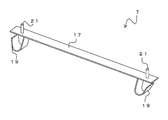
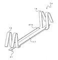
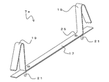
- the perspective view which shows the fixing metal fitting 7. The figure which shows the construction method of a fireproof structure 1.
- FIG. 5A is a sectional view taken along line BB.
- FIG. 6A is a sectional view taken along line CC.
- FIG. 9A is a sectional view taken along line DD.
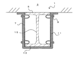
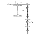
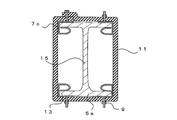
- FIG. 1A is a front view showing the fireproof structure 1 according to the first embodiment
- FIG. 1B is a sectional view taken along line AA of FIG. 1A.
- the fireproof structure 1 is a structure in which a beam 5 is coated with a fireproof covering material 11.
- the beam 5 is a so-called H-shaped steel in which a pair of flange portions 13 are connected by a web 15.
- the structure is not particularly limited as long as it has a flange portion 13, such as I-shaped steel, L-shaped steel, and angle steel.
- a floor 3 is installed on the upper part of the beam 5.
- a fixing bracket 7 for fixing the refractory covering material 11 to the beam 5 is fixed to the beam 5.
- the floor 3 is in contact with the beam 5, and a gap into which the fixing bracket 7 or the like can be inserted is not formed between the floor 3.
- the fixing bracket 7 has a main body portion 17 and spring portions 19 provided in the vicinity of both ends of the main body portion 17, respectively.
- the spring portion 19 is a portion for fixing the fixing bracket 7 to the flange portion 13 of the beam 5.
- the protrusion 21 projects toward the outer surface of the main body 17 (the surface opposite to the spring 19). That is, the fixing bracket 7 has a protrusion protruding outward.
- the protrusions 21 are arranged in the vicinity of both ends of the main body 17 and at substantially the same positions as the positions of the springs 19.
- the spring portion 19 and the protrusion portion 21 are joined to the plate-shaped main body portion 17 by, for example, welding.
- the protrusion 21 is, for example, pin-shaped and more preferably a male screw so that it can be pierced into the refractory coating material as described later.
- the material of the fixing bracket 7 is not particularly limited, but for example, an iron plate, a galvanized steel plate, a stainless steel plate, or the like can be applied, and in consideration of springiness, a stainless steel plate for spring is particularly suitable.
- protrusions 21 are not limited to the illustrated example.
- the protrusion 21 may be further arranged substantially in the center of the main body 17 in the longitudinal direction.
- shape of the spring portion 19 is not limited to the illustrated example, and is not particularly limited as long as the effect of the present embodiment can be obtained.
- the fixing bracket 7 is arranged between the pair of flange portions 13 formed on the beam 5.
- the distance between both ends of the pair of spring portions 19 is slightly larger than the distance between the flange portions 13. Therefore, the fixing bracket 7 is inserted between the flange portions 13 while the spring portion 19 is elastically deformed. In this way, each of the spring portions 19 has a restoring force toward the outside, and the fixing bracket 7 is fixed to the beam 5 by being pressed toward the inner surface side of the flange portion 13.
- the fixing brackets 7 are arranged on both sides of the beam 5. Further, the fixing metal fittings 7 are arranged at predetermined intervals with respect to the longitudinal direction of the beam 5. For example, the fixing brackets 7 are arranged at intervals according to the width of the refractory covering material 11.
- the refractory coating material 11 is fixed to the fixing bracket 7. At this time, the protrusion 21 is pierced into the fireproof coating material 11, so that the fireproof coating material 11 is fixed to the fixing bracket 7.
- the fireproof coating material 11 is a flexible member, and the beam 5 is covered with the fireproof coating material 11 by fixing the fireproof coating material 11 in a state of being wound around the beam 5.
- the fireproof coating material 11 is preferably a sheet-like member containing, for example, a thermal expansion material.
- the refractory coating material 11 is preferably made of a resin as a base material, not by an inorganic fiber such as rock wool as a main component. That is, it is desirable that the refractory coating material 11 is composed of a resin as a base material containing a thermal expansion material.
- the resin is not particularly limited, but for example, a thermoplastic resin, a thermosetting resin, rubber, an elastomer, or the like can be applied.
- the thermal expansion material contained in the resin is not particularly limited, and examples thereof include layered inorganic substances and phosphorus compounds.
- the layered inorganic substance examples include vermiculite, carion, mica, and heat-expandable graphite, and heat-expandable graphite is particularly preferable.
- a glass frit, an inorganic filler, or the like may be added to the resin.
- the refractory coating material 11 may be a foam or a non-foam.
- the fireproof coating material 11 may be combined with other members.
- the other members are not particularly limited as long as the effects of the present embodiment are not impaired, but members exhibiting heat resistance and / or flame retardancy are preferable.
- Examples of the composite in which the fireproof coating material 11 and other members are combined include a composite in which the fireproof coating material 11 and a noncombustible sheet are bonded together, and examples of the noncombustible sheet include a metal sheet and an inorganic fiber sheet. ..
- the metal sheet a metal sheet made of stainless steel, aluminum, iron or the like can be used. By forming the complex with the metal sheet in this way, the fire resistance can be further improved.
- a composite material of the refractory coating material 11 and the inorganic fiber sheet can also be mentioned.
- the inorganic fiber sheet include a sheet made of glass fiber, cellulose fiber, ceramic wool fiber, rock wool fiber and the like, a non-woven fabric, a woven fabric and the like.
- the non-woven fabric and the woven fabric may be those in which a thin aluminum layer is laminated.
- One kind or two or more kinds of such non-combustible sheets can be used.
- the protrusion 21 is a male screw. Therefore, the fireproof coating material 11 can be reliably fixed to the fixing bracket 7 by piercing the fireproof coating material 11 with a male screw and tightening the nut 9 from the outer surface side of the fireproof coating material 11. If a so-called round speed nut (Rond Type Speed Nut) is used as the nut 9, it can be easily fixed only by inserting it into a male screw, which is more preferable.
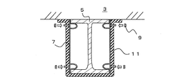
- the upper end portion of the fireproof coating material 11 may be arranged so as to abut against the lower surface of the floor 3, but as shown in FIG. 1B, the vicinity of the upper end portion of the fireproof coating material 11 may be arranged along the lower surface of the floor 3. It may be folded back. By doing so, the beam 5 can be more reliably covered with the fireproof coating material 11 without any gaps. Further, also in the longitudinal direction of the beam 5, the widthwise ends of the refractory covering materials 11 may be butted against each other, but they may be arranged so as to wrap each other. In this case, the protrusion 21 may be pierced into the overlapping portion of the refractory covering material 11 and fixed together.
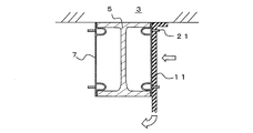
- the construction method of the fireproof structure 1 for fixing the fireproof covering material 11 to the structure by using the fixing metal fitting 7 will be described.
- the fixing bracket 7 is inserted between the flange portions 13 of the beam 5 and fixed to the beam 5 by the spring portion 19.
- the protrusion 21 of the fixing bracket 7 is pierced into the fireproof coating material 11 to attach the fireproof coating material 11 to the fixing bracket 7.
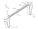
- the refractory coating material 11 is pierced into the protrusion 21 of the fixing bracket 7 to fix the refractory coating material 11 to the beam 5, and the refractory coating material 11 is bent to cover the beam 5 over the entire circumference.
- the nut 9 is attached to the protrusion 21 (male screw) from the outer surface side of the refractory coating material 11. From the above, the fireproof structure 1 can be constructed.
- the construction method of the fireproof structure 1 is not limited to the above example.
- the protrusion 21 of the fixing bracket 7 may be pierced into a predetermined position of the fireproof coating material 11 to fix the fixing bracket 7 to the fireproof coating material 11.
- the refractory covering material 11 to which the fixing bracket 7 is fixed is transported to the installation site. Since the nut 9 is tightened to the protrusion 21 of the fixing bracket 7, the fireproof coating material 11 does not fall off from the protrusion 21 during transportation.
- the fixing bracket 7 fixed to the refractory covering material 11 is fixed to the beam 5 by the spring portion 19. Further, as shown in FIG. 4B, the refractory covering material 11 is wound around the beam 5 and the fixing bracket 7 is fixed to the beam 5, so that the refractory covering material 11 is fixed to the beam 5 to construct the fireproof structure 1. be able to.
- the fixing bracket 7 is fixed to the beam 5 by the spring portion 19, welding is not required and the fixing bracket 7 can be easily fixed to the beam 5. Further, the fireproof coating material 11 can be fixed to the fixing metal fitting 7 only by piercing the fireproof coating material 11 into the protrusion 21 of the fixing metal fitting 7. Therefore, the refractory covering material 11 can be easily fixed to the beam 5.
- the protrusion 21 is a male screw
- the nut 9 can surely prevent the refractory coating material 11 from falling off.
- the refractory coating material 11 is made of a resin containing a thermal expansion material, deterioration of the working environment is suppressed, and the work is easy because it is lightweight.
- resin as the base material it has excellent water resistance and can suppress deterioration during transportation compared to conventional rock wool and the like whose main component is inorganic fiber, so transportation work is easy. Is.
- the beam 5 is covered with the fireproof coating material 11 as a structure
- the protrusion 21 does not have to be a male screw, and may be, for example, a wire-shaped pin.
- the fireproof coating material 11 can be prevented from falling off by piercing the protrusion 21 into the fireproof coating material 11 and then bending the tip thereof.
- the fixing metal fitting 7 may fall off from the structure. Therefore, the main body 17 of the fixing bracket 7 may be reinforced.
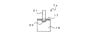
- FIG. 5A is a perspective view showing the fixing bracket 7a
- FIG. 5B is a sectional view taken along line BB of FIG. 5A.
- the fixing bracket 7a has substantially the same structure as the fixing bracket 7, but differs in that a reinforcing rib 23 is formed on the main body 17.
- a rib 23 is formed on the main body 17 so as to project toward the back surface along the longitudinal direction.
- the rib 23 is formed between the protrusions 21. Since the rib 23 increases the rigidity of the main body portion 17, it is possible to suppress the bending of the main body portion 17 due to the weight of the refractory covering material 11 or the like.
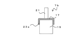
- the shape of the rib is not limited to the example shown in FIG. 6A is a perspective view showing the fixing bracket 7b, and FIG. 6B is a sectional view taken along line CC of FIG. 6A.
- the fixing bracket 7b has substantially the same structure as the fixing bracket 7a, but differs in that the rib 23a is formed.
- both ends of the main body 17 in the width direction are bent toward the back surface to form ribs 23a. That is, the main body portion 17 is formed in a substantially U shape in a cross section perpendicular to the longitudinal direction. Since the rib 23a increases the rigidity of the main body portion 17, it is possible to suppress the bending of the main body portion 17 due to the weight of the refractory covering material 11 or the like.
- FIG. 7 is a perspective view showing the fixing bracket 7d.
- the fixing bracket 7d has substantially the same structure as the fixing bracket 7b, except that the main body portion 17 and the spring portion 19 are formed of a single plate-shaped material.
- a pair of spring portions 19 are formed on both sides in the width direction in the vicinity of the respective ends, and a part of the main body portion 17 protrudes toward the end portion between the spring portions 19, and the protrusion portion 21 is formed at the portion. Is formed.
- both sides of the main body 17 in the width direction are bent to function as ribs 23b. By doing so, it functions in the same manner as the fixing bracket 7b and the like, and the fixing bracket 7d can be easily manufactured.
- FIG. 8A is an upward perspective view showing the fixing bracket 7e
- FIG. 8B is a downward perspective view showing the fixing bracket 7e.
- the fixing bracket 7e has substantially the same structure as the fixing bracket 7a and the like, but differs in that the plate-shaped member forming the spring portion 19 and the plate-shaped member having the protrusion 21 are joined by the rivet 25.
- the rib 23c may be formed on either one of the plate-shaped member forming the spring portion 19 and the plate-shaped member having the protrusion 21.
- jagged teeth may be formed at the tip of the spring portion 19. By doing so, the tip of the spring portion 19 can be easily bitten into another member. Such teeth are also applicable to other fixing brackets.
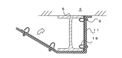
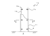
- FIG. 9A is a diagram showing a fireproof structure 1a
- FIG. 9B is a sectional view taken along line DD of FIG. 9A.
- the same components as those of the fireproof structure 1 and the like are designated by the same reference numerals as those in FIGS. 1 to 8, and duplicated description will be omitted.
- the pillar 5a which is a structure, is covered with the fireproof coating material 11. At this time, the refractory covering material 11 is fixed to the pillar 5a by the fixing metal fitting 7c.
- FIG. 10 is a perspective view of the fixing bracket 7c.
- the fixing bracket 7c is formed with a spring portion 19 for fixing to the flange portion 13 of the structure.
- the spring portion 19 is formed so as to face the main body portion 17.
- the protrusion 21 protrudes to the outside of the main body 17. More specifically, the plate-shaped main body 17 is bent in the direction opposite to the protruding direction of the protrusion 21, and the spring portion 19 is formed so as to face the back surface side of the protrusion 21.
- Fixing brackets 7c are fixed to both ends of each flange portion 13 of the pillar 5a. That is, the fixing metal fittings 7c are arranged at four places at substantially the same height as the pillars 5a.
- the refractory covering material 11 is wound around the pillar 5a. At this time, the fireproof coating material 11 is fixed to the pillar 5a by piercing the protrusion 21 into the fireproof coating material 11. Although the ends of the refractory covering material 11 may be butted against each other, it is desirable to wrap the ends with each other. At this time, in the wrap portion, the protrusion 21 may be passed through the two refractory covering materials 11 and fixed together.
- the fireproof structure 1a can also be constructed by the same method as the fireproof structure 1. That is, the fixing metal fitting 7c can be fixed to the pillar 5a at a predetermined position, and the refractory covering material 11 can be pierced into the protrusion 21 of the fixed fixing metal fitting 7c and wound around the pillar 5a to be fixed. Even in this case, the fireproof coating material 11 can be securely fixed by the nut 9 after the fireproof coating material 11 has been wound.
- the protrusion 21 of the fixing bracket 7c may be pierced and fixed in advance at a predetermined position of the fireproof coating material 11.
- the fixing bracket 7c can be fixed to the refractory coating material 11 in advance by the nut 9.
- the fireproof covering material 11 can be easily fixed to the pillar 5a by winding the fixing metal fitting 7c around the pillar 5a while attaching the fixing metal fitting 7c to the pillar 5a. can.
- the same effect as that of the first embodiment can be obtained. Further, the fixing bracket 7c can be used regardless of the distance between the flange portions 13.
Landscapes
- Engineering & Computer Science (AREA)
- Architecture (AREA)
- Physics & Mathematics (AREA)
- Electromagnetism (AREA)
- Civil Engineering (AREA)
- Structural Engineering (AREA)
- Building Environments (AREA)
Priority Applications (1)
| Application Number | Priority Date | Filing Date | Title |
|---|---|---|---|
| JP2021557572A JP7763101B2 (ja) | 2020-06-30 | 2021-06-25 | 耐火構造、耐火構造の施工方法及び固定金具 |
Applications Claiming Priority (2)
| Application Number | Priority Date | Filing Date | Title |
|---|---|---|---|
| JP2020113278 | 2020-06-30 | ||
| JP2020-113278 | 2020-06-30 |
Publications (1)
| Publication Number | Publication Date |
|---|---|
| WO2022004591A1 true WO2022004591A1 (ja) | 2022-01-06 |
Family
ID=79316284
Family Applications (1)
| Application Number | Title | Priority Date | Filing Date |
|---|---|---|---|
| PCT/JP2021/024137 Ceased WO2022004591A1 (ja) | 2020-06-30 | 2021-06-25 | 耐火構造、耐火構造の施工方法及び固定金具 |
Country Status (2)
| Country | Link |
|---|---|
| JP (1) | JP7763101B2 (enExample) |
| WO (1) | WO2022004591A1 (enExample) |
Citations (6)
| Publication number | Priority date | Publication date | Assignee | Title |
|---|---|---|---|---|
| JPH0740823U (ja) * | 1993-12-28 | 1995-07-21 | 順三 白鳥 | 耐火・防火用断熱材の取付金具 |
| JPH07189359A (ja) * | 1993-12-27 | 1995-07-28 | Ask:Kk | 鉄骨耐火被覆構造および鉄骨耐火被覆工法 |
| JPH086892Y2 (ja) * | 1989-12-07 | 1996-02-28 | 株式会社フジタ | 鉄骨梁への耐火被覆材取付構造 |
| JP2672512B2 (ja) * | 1987-08-05 | 1997-11-05 | 株式会社 三和クリ−ン | 被覆材取付用スペーサ |
| JP3103925B2 (ja) * | 1991-03-04 | 2000-10-30 | 積水ハウス株式会社 | 耐火被覆材の取付装置 |
| JP2013234459A (ja) * | 2012-05-07 | 2013-11-21 | Sekisui Chem Co Ltd | 鉄骨の耐火被覆構造 |
-
2021
- 2021-06-25 WO PCT/JP2021/024137 patent/WO2022004591A1/ja not_active Ceased
- 2021-06-25 JP JP2021557572A patent/JP7763101B2/ja active Active
Patent Citations (6)
| Publication number | Priority date | Publication date | Assignee | Title |
|---|---|---|---|---|
| JP2672512B2 (ja) * | 1987-08-05 | 1997-11-05 | 株式会社 三和クリ−ン | 被覆材取付用スペーサ |
| JPH086892Y2 (ja) * | 1989-12-07 | 1996-02-28 | 株式会社フジタ | 鉄骨梁への耐火被覆材取付構造 |
| JP3103925B2 (ja) * | 1991-03-04 | 2000-10-30 | 積水ハウス株式会社 | 耐火被覆材の取付装置 |
| JPH07189359A (ja) * | 1993-12-27 | 1995-07-28 | Ask:Kk | 鉄骨耐火被覆構造および鉄骨耐火被覆工法 |
| JPH0740823U (ja) * | 1993-12-28 | 1995-07-21 | 順三 白鳥 | 耐火・防火用断熱材の取付金具 |
| JP2013234459A (ja) * | 2012-05-07 | 2013-11-21 | Sekisui Chem Co Ltd | 鉄骨の耐火被覆構造 |
Also Published As
| Publication number | Publication date |
|---|---|
| JPWO2022004591A1 (enExample) | 2022-01-06 |
| JP7763101B2 (ja) | 2025-10-31 |
Similar Documents
| Publication | Publication Date | Title |
|---|---|---|
| KR100538079B1 (ko) | 벽구조 | |
| WO2022004591A1 (ja) | 耐火構造、耐火構造の施工方法及び固定金具 | |
| JP2002061339A (ja) | 耐火断熱屋根構造 | |
| JP2013079553A (ja) | コンクリート充填鋼管柱の耐火補強構造 | |
| JP4545924B2 (ja) | 耐火建物構造 | |
| RU2767836C1 (ru) | Строительная система и способ возведения здания | |
| JP7536729B2 (ja) | 耐火被覆材用固定金具、耐火構造および耐火構造の施工方法 | |
| JP6508289B2 (ja) | 鉄骨柱の合成被覆耐火構造の施工方法 | |
| JP7488236B2 (ja) | 耐火被覆材用固定金具、耐火構造および耐火構造の施工方法 | |
| JP7488237B2 (ja) | 耐火被覆材用固定金具、耐火構造および耐火構造の施工方法 | |
| JP2017089266A (ja) | 鋼製耐震壁の耐火構造 | |
| JP2025033354A (ja) | 断熱材固定金具および鉄骨造建物の断熱構造 | |
| JP2921366B2 (ja) | 金属複合屋根材及びその施工方法 | |
| KR102814815B1 (ko) | 화재 확산 방지용 외벽 패널 조립체 | |
| JP2019112799A (ja) | 被覆構造体 | |
| JPH0960145A (ja) | 建築用外装材及び建築用外装材を使用した建築用外装パネル | |
| JPH11280203A (ja) | スチ−ルハウスの組立構造及び組立ユニット | |
| JP5814590B2 (ja) | 建築用パネルの接続構造 | |
| CN218522115U (zh) | 一种连接龙骨及其防火墙板结构 | |
| JP7197926B2 (ja) | 耐火被覆方法、鉄骨梁及び耐火被覆材 | |
| KR102476088B1 (ko) | 내화 패널의 보강재 및 이 보강재를 사용한 내화 패널 | |
| JP2020066853A (ja) | 木製建築部材 | |
| JP7197925B2 (ja) | 耐火被覆方法及び鉄骨梁 | |
| JPH11324170A (ja) | 耐力パネル及び耐力パネルの接合構造 | |
| JP2009139042A (ja) | 軽量不燃性ダクト |
Legal Events
| Date | Code | Title | Description |
|---|---|---|---|
| ENP | Entry into the national phase |
Ref document number: 2021557572 Country of ref document: JP Kind code of ref document: A |
|
| 121 | Ep: the epo has been informed by wipo that ep was designated in this application |
Ref document number: 21834283 Country of ref document: EP Kind code of ref document: A1 |
|
| NENP | Non-entry into the national phase |
Ref country code: DE |
|
| 122 | Ep: pct application non-entry in european phase |
Ref document number: 21834283 Country of ref document: EP Kind code of ref document: A1 |