WO2022004272A1 - 電子機器の温度調整構造 - Google Patents
電子機器の温度調整構造 Download PDFInfo
- Publication number
- WO2022004272A1 WO2022004272A1 PCT/JP2021/021326 JP2021021326W WO2022004272A1 WO 2022004272 A1 WO2022004272 A1 WO 2022004272A1 JP 2021021326 W JP2021021326 W JP 2021021326W WO 2022004272 A1 WO2022004272 A1 WO 2022004272A1
- Authority
- WO
- WIPO (PCT)
- Prior art keywords
- region
- electronic device
- air
- air supply
- vehicle
- Prior art date
- Legal status (The legal status is an assumption and is not a legal conclusion. Google has not performed a legal analysis and makes no representation as to the accuracy of the status listed.)
- Ceased
Links
Images









Classifications
-
- H—ELECTRICITY
- H05—ELECTRIC TECHNIQUES NOT OTHERWISE PROVIDED FOR
- H05K—PRINTED CIRCUITS; CASINGS OR CONSTRUCTIONAL DETAILS OF ELECTRIC APPARATUS; MANUFACTURE OF ASSEMBLAGES OF ELECTRICAL COMPONENTS
- H05K7/00—Constructional details common to different types of electric apparatus
- H05K7/20—Modifications to facilitate cooling, ventilating, or heating
- H05K7/20009—Modifications to facilitate cooling, ventilating, or heating using a gaseous coolant in electronic enclosures
- H05K7/20136—Forced ventilation, e.g. by fans
- H05K7/20145—Means for directing air flow, e.g. ducts, deflectors, plenum or guides
-
- H—ELECTRICITY
- H01—ELECTRIC ELEMENTS
- H01Q—ANTENNAS, i.e. RADIO AERIALS
- H01Q1/00—Details of, or arrangements associated with, antennas
- H01Q1/27—Adaptation for use in or on movable bodies
- H01Q1/32—Adaptation for use in or on road or rail vehicles
- H01Q1/325—Adaptation for use in or on road or rail vehicles characterised by the location of the antenna on the vehicle
-
- H—ELECTRICITY
- H01—ELECTRIC ELEMENTS
- H01Q—ANTENNAS, i.e. RADIO AERIALS
- H01Q1/00—Details of, or arrangements associated with, antennas
- H01Q1/02—Arrangements for de-icing; Arrangements for drying-out ; Arrangements for cooling; Arrangements for preventing corrosion
-
- H—ELECTRICITY
- H01—ELECTRIC ELEMENTS
- H01Q—ANTENNAS, i.e. RADIO AERIALS
- H01Q1/00—Details of, or arrangements associated with, antennas
- H01Q1/52—Means for reducing coupling between antennas; Means for reducing coupling between an antenna and another structure
- H01Q1/526—Electromagnetic shields
-
- H—ELECTRICITY
- H05—ELECTRIC TECHNIQUES NOT OTHERWISE PROVIDED FOR
- H05K—PRINTED CIRCUITS; CASINGS OR CONSTRUCTIONAL DETAILS OF ELECTRIC APPARATUS; MANUFACTURE OF ASSEMBLAGES OF ELECTRICAL COMPONENTS
- H05K7/00—Constructional details common to different types of electric apparatus
- H05K7/20—Modifications to facilitate cooling, ventilating, or heating
- H05K7/20845—Modifications to facilitate cooling, ventilating, or heating for automotive electronic casings
- H05K7/20863—Forced ventilation, e.g. on heat dissipaters coupled to components
Definitions
- the present invention relates to a temperature control structure of an electronic device and the like.
- Patent Document 1 Conventionally, an electronic device provided inside a vehicle has been proposed, such as the transmission / reception unit shown in Patent Document 1.
- the temperature of the electronic device installed inside the vehicle may become too high or too low, and it may be necessary to adjust the temperature.
- an object of the present invention is to provide a temperature control structure of an electronic device provided inside a vehicle.
- the temperature control structure of the electronic device provided inside the vehicle according to the present invention includes the first region.
- the first region is a region different from the first region through the air supply port and has cold air or warm air as compared with the first region, and at least one of the duct of the air conditioner of the vehicle. Communicate with one.
- the air that has flowed into the air supply port flows into the region where the electronic device in the first region is located.
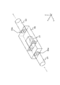
- FIG. 3 is an enlarged perspective view of a region having a first region in FIG. 1. It is a schematic diagram which shows the comparison of the cross-sectional area of the front stage region, the central stage region, the rear stage region, the air supply opening, and the exhaust opening of the first embodiment. It is sectional drawing which looked at the space including the driver's seat of the vehicle which includes the air supply port which takes in air from the 2nd region of 1st Embodiment from the inside.
- the portion adjacent to the central region of the front stage region, the central region, and the portion adjacent to the central region of the rear stage region the upper surface of the central region is omitted.
- the portion adjacent to the central region of the front stage region, the central region, and the portion adjacent to the central region of the rear stage region the upper surface of the central region is omitted.
- the vehicle 1 of the first embodiment includes an electronic device (antenna device) 10 and a first region (cooling air introduction region) 50.
- the left-right direction of the vehicle 1 provided with the first region 50 is defined as the x direction
- the front-rear direction perpendicular to the x direction is defined as the y direction
- the substantially vertical direction perpendicular to the x direction and the y direction is defined as the z direction. do.
- the directions pointed to by the arrows on the xyz axis are defined as the left direction, the forward direction, and the upward direction, respectively.
- the perspective views of FIGS. 1 and 5 show the contents (first region 50) of the first region 50, which is not actually visible from the outside, but in order to explain the invention, the contents (first region 50) are seen through and the central region 55.
- FIG. 6 shows a state in which the contents (electronic device 10) of the electronic device 10 are seen through, although they are not actually visible from the outside, in order to explain the invention.
- FIG. 9 of the third embodiment shows a state in which the direction of the air flow.
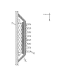
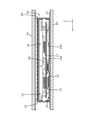
- the electronic device 10 is an antenna device or the like. In the first embodiment, the electronic device 10 will be described as an antenna device, but other devices may be used. As shown in FIG. 2, the electronic device 10 as an antenna device includes an antenna case (housing) 11, a substrate 13, an antenna element 15, a mounting component 17, a ground plate 19, a heat absorbing / radiating member 21, a heat conductive material 23, and heat insulating material. It has a material 25, a heat storage material 26, and a bracket 27.
- the antenna case 11 constitutes the side surface and the upper surface of the electronic device 10.
- the antenna case 11 is made of a synthetic resin having radio wave transmission.
- the antenna case 11 covers a member constituting the electronic device 10 such as the substrate 13 from above in the z direction.
- the antenna case 11 is preferably made of a resin having high thermal conductivity.
- An air supply opening 11a is provided on the front surface of the antenna case 11.
- the front surface of the antenna case 11 is a side surface of the side surface constituting the antenna case 11 that faces the front stage region 51 when the electronic device 10 is housed in the central region 55 of the first region 50 described later.
- An exhaust opening 11b is provided on the back surface of the antenna case 11.
- the back surface of the antenna case 11 is a side surface of the side surface constituting the antenna case 11 that faces the subsequent region 53 when the electronic device 10 is housed in the central region 55.
- the antenna element 15 transmits and receives electrical signals.
- the antenna element 15 includes a planar antenna for receiving satellite broadcasts, a planar antenna for receiving position information (time information) from satellites such as GPS, a capacitive loading element for receiving AM / FM broadcasts, and a capacitive loading element.
- Antennas including coils, antennas for V2X (vehicle-to-vehicle / road-to-vehicle communication), and antennas for communication terminals can be considered.
- the antenna element 15 is held on the substrate 13. However, the antenna element 15 may be held by the ground plate 19 or may be held by the antenna case 11. Further, a part of the antenna element 15 may be in contact with the inner wall of the antenna case 11.
- the antenna element 15 is preferably made of a metal having high thermal conductivity, such as a copper alloy or an aluminum alloy.
- the first embodiment shows an example in which the antenna element 15 is provided inside the antenna case 11. However, a part or all of the antenna element 15 may be provided on the outside of the antenna case 11.
- the mounting component 17 is a circuit that includes a semiconductor and performs signal processing on electrical signals transmitted and received by the antenna element 15, such as an amplifier circuit and a tuning circuit.
- the mounting component 17 is mounted on the front surface (upper surface) or the back surface (lower surface) of the substrate 13.
- the ground plate 19 is, for example, a metal plate that functions as an antenna base.
- the substrate 13 and the mounting component 17 are connected to the ground plate 19 via the heat conductive material 23.
- the ground plate 19 is arranged below the substrate 13 and away from the substrate 13.
- the heat absorbing / radiating member 21 is composed of a heat sink or the like including fins for heat dissipation, and is attached to a heat generating region of the substrate 13, a heat generating region of the mounting component 17, or the like.
- the heat absorbing / radiating member 21 is used to radiate the heat of the members constituting the electronic device 10, particularly the heat generating region of the substrate 13 and the heat generating region of the mounting component 17.
- it is desirable that the heat absorbing / radiating member 21 is provided on the lower surface of the substrate 13 rather than the upper surface.
- Each heat absorbing / radiating member 21 so that the surface area of the part of the corresponding heat absorbing / radiating member 21 that comes into contact with the outside air is larger than the area of the part where the heat absorbing / radiating member 21 of the substrate 13 or the mounting component 17 is directly or indirectly attached. Dimensions and shape are determined.
- the heat absorbing / radiating member 21 is not limited to a fin having an uneven shape, but may be a plate-shaped member.
- the heat absorbing / radiating member 21 is not limited to metal, and may be made of resin or the like.
- the heat conductive material (TIM: Thermal Interface Material) 23 includes a silicon sheet, a thermal grease heat conductive sheet, a phase change material (PCM: Phase Change Material), a gel (heat conductive gap filler), a high heat conductive adhesive, and a thermal tape (thermal tape). It is composed of heat-conducting double-sided tape).
- the heat conductive material 23 is provided between the substrate 13 and the ground plate 19, between the mounting component 17 and the ground plate 19, and the like.
- the heat conductive material 23 accumulates the heat of the contacted member (board 13, mounting component 17, etc.) or transfers it to another member such as the ground plate 19.
- the heat conductive material 23 is used for heat exchange between the heat generating portion of the substrate 13 and the mounting component 17 and the ground plate 19.
- the heat conductive material 23 may be provided between the substrate 13 and the heat absorbing / radiating member 21, and also between the mounting component 17 and the heat absorbing / radiating member 21.
- a shielding plate 24 may be provided around the mounting component 17 to prevent noise generated by the mounting component 17 from affecting other components such as the antenna element 15 (see FIG. 3).
- the heat conductive material 23 is provided between the mounting component 17 and the shielding plate 24.
- the shielding plate 24 and the heat absorbing / radiating member 21 may be configured separately, but as shown in FIG. 4, the shielding plate 24 and the heat absorbing / radiating member 21 are It may be integrally configured. In this case, the configuration of the heat absorbing / radiating member 21 and the shielding plate 24 can be simplified, and the heat transfer efficiency can be improved.
- the heat insulating material 25 is provided on the upper surface of the antenna case 11.
- the heat insulating material 25 is provided to make it difficult for heat from the outside such as sunlight to be transferred to the inside of the electronic device 10.
- the heat storage material 26 is composed of a phase change heat storage material such as paraffin, and is used to slow down the temperature rise inside the electronic device 10.
- the heat storage material 26 is placed on the substrate 13 or the like in a state of being placed in a closed container such as a capsule.
- Bracket 27 The bracket 27 is made of a metal member and is arranged on the central region 55 of the first region 50.
- the electronic device 10 is mounted on the bracket 27 so that the lower surface of the ground plate 19 is in contact with the upper surface of the bracket 27.
- the bracket 27 is attached to the lower surface of the first region 50, but may be suspended from another surface (for example, the upper surface).
- the first region 50 is provided inside the vehicle 1 and houses the electronic device 10 inside.
- the first region 50 takes in air from a region different from the first region 50 (such as the second region 70), and cools the electronic device 10 by using the taken-in air. That is, the first region 50 constitutes the temperature control structure of the electronic device 10.
- the region (central region 55) accommodating the electronic device 10 and the electronic device 10 of the first region 50 is provided in the region between the roof 1a and the roof lining 1b of the vehicle 1.
- the electronic device 10 and the central region 55 are not limited to the form provided between the roof 1a and the roof lining 1b.
- the electronic device 10 and the central region 55 may be provided in another region different from the second region 70 of the vehicle 1.
- the first region 50 has a front region 51, a rear region 53, a central region 55, and a fan 57.
- the central region 55 is provided between the front region 51 and the rear region 53.
- the front region 51, the center region 55, and the rear region 53 are arranged in the x direction.
- the front region 51 is composed of a tubular member. One end of the front region 51 opens as an air supply port 51a.
- the front-stage region 51 communicates with the second region 70, which will be described later, via the air supply port 51a.
- the pre-stage region 51 communicates with the first end region 55a including one end of the central region 55, that is, the region in contact with the other end of the pre-stage region 51, via the other end of the pre-stage region 51. ..
- the rear region 53 is composed of a tubular member. One end of the posterior region 53 communicates with a second end region 55b that includes the other end of the central region 55, i.e., a region in contact with one end of the posterior region 53. The other end of the trailing region 53 opens as an exhaust port 53a.
- the rear region 53 communicates with an region different from the space including the driver's seat, the passenger seat, and the rear seat (hereinafter, referred to as “the space including the driver's seat”) such as the trunk room through the exhaust port 53a.
- the central region 55 is an region for accommodating the electronic device 10.
- the yz cross section of the central region 55 is larger than the yz cross section of the front region 51 and the rear region 53.
- Holes (not shown) through which cables or connectors for electrical connection between the electronic device 10 and other devices inside the vehicle 1 pass are provided on the bottom surface, side surfaces, and the like of the central region 55.
- the fan 57 takes in the air in the second region 70 from the air supply port 51a and discharges the air in the first region 50 from the exhaust port 53a.
- the fan 57 is provided in at least one of the front stage region 51, the central stage region 55, and the rear stage region 53.
- one fan 57 is provided in the front region 51 for air supply and one in the rear region 53 for exhaust.
- one fan 57 may be provided in the front stage region 51 or the rear stage region 53 for both air supply and exhaust.
- FIG. 5 an example in which one fan 57 is provided in the front-stage region 51 is shown (see FIG. 5).
- the on / off control of the fan 57 is not limited to this.
- the on / off control of the fan 57 is performed by an ECU (Electronic Control Unit, not shown) of the vehicle 1.
- the cross-sectional area of the yz cross section (flow path cross section) of each part of the first region 50 has the following relationship. Is determined (see FIG. 6).
- the cross-sectional area A1 of the yz cross section of the front stage region 51 is smaller than the opening area A4 of the air supply opening 11a and the exhaust opening 11b (A1 ⁇ A4).
- the difference A2 between the cross-sectional area of the yz cross section of the central region 55 and the cross-sectional area of the yz cross section of the electronic device 10 is smaller than the opening areas A4 of the air supply opening 11a and the exhaust opening 11b (A2 ⁇ A4).
- the cross-sectional area A1 of the yz cross section of the front stage region 51 is the same as or smaller than the cross-sectional area A3 of the yz cross section of the rear stage region 53 (A1 ⁇ A3).
- FIG. 6 schematically shows the relationship between the size of the opening area A4 of the intake opening 11a and the exhaust opening 11b, the cross-sectional area A1 of the front region 51, the cross-sectional area A3 of the rear region 53, and the difference A2 of the cross-sectional area. It is. That is, the shapes of the intake opening 11a and the exhaust opening 11b, including the shapes of the intake opening 11a and the exhaust opening 11b shown in FIG. 2, may be any shape as long as they have the above-mentioned size relationship.
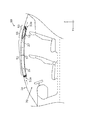
- the second region 70 is a region different from the first region 50 of the vehicle 1, for example, a region under the roof lining 1b of the vehicle 1, that is, a space including a driver's seat. That is, in the first embodiment, the second region 70 corresponds to a region different from the first region 50 and having air colder than the first region 50. In this case, an air supply port 51a is provided near the roof lining 1b above the side of the space including the driver's seat (see FIG. 7).
- the electronic device 10 is installed in the first area 50 in advance, and the first area 50 is installed in the vehicle 1.
- the accessory switch of the vehicle 1 is turned on, such as turning on the engine of the vehicle 1, the fan 57 operates during the first time T1.
- the electronic device 10 may be turned on while the accessory switch of the vehicle 1 is turned on, and part or all of the electronic device 10 may or may not have the accessory switch turned on. It may be turned on.
- the air in the second region 70 flows into the front region 51 of the first region 50 through the air supply port 51a.
- the air that has flowed into the front region 51 flows into the central region 55.
- the air that has flowed into the central region 55 flows into the inside of the electronic device 10 through the air supply opening 11a.
- the air that has flowed into the inside of the electronic device 10 exchanges heat with a member inside the electronic device 10 such as the substrate 13, cools the member, and is discharged from the exhaust opening 11b.
- the air after heat exchange discharged from the exhaust opening 11b passes through the subsequent region 53.
- the air is discharged to a region inside the vehicle 1 such as a trunk room, which is different from the space including the driver's seat, or a third region 80, which will be described later, via the exhaust port 53a.
- Air is taken into the front region 51 of the first region 50 from the second region 70 or the like through the air supply port 51a, and the taken air is used for temperature adjustment of the electronic device 10.
- the temperature of the electronic device 10 can be easily adjusted as compared with the case where the temperature is not adjusted by using the air from the outside different from the area where the electronic device 10 is arranged.
- the air continues to flow to the electronic device 10. Therefore, it is easy to keep the member of the electronic device 10 in a dry state.
- the "temperature adjustment” in the present embodiment means adjusting the temperature so as not to affect the performance of the electronic device 10. For example, when it has been obtained through experiments or the like that the performance of the electronic device 10 is affected when the temperature exceeds a predetermined temperature or becomes lower than a predetermined temperature in a certain environment, the "temperature adjustment” in the present embodiment may be used. It means adjusting so as not to be above the predetermined temperature or below the predetermined temperature.
- the second region 70 is located at a position lower than that of the first region 50, and may be in a different temperature state from the first region 50. For example, under the scorching sun where the temperature is high, there is a high possibility that the space including the driver's cab (second region 70) is in a lower temperature state than directly under the roof 1a (first region 50). Therefore, the temperature of the electronic device 10 can be adjusted by the air flowing in from the second region 70.
- the second area 70 is not limited to the space including the driver's seat, and may be a space other than the space including the first area 50 and the driver's seat in the vehicle 1 such as a trunk room.
- a region different from the first region 50 and having colder air than the first region 50 is an internal region of the vehicle 1 (second region 70) such as a space including a driver's seat, and the first region.
- second region 70 an internal region of the vehicle 1
- the front-stage region 51 of the region 50 communicates with the second region 70 has been described.
- a region different from the first region 50 and having cooler air than the first region 50 may be a region outside the vehicle 1. That is, the front region 51 of the first region 50 may communicate with the third region 80 outside the vehicle 1 and at a position lower than the first region 50 via the air supply port 51a (second region 50). Embodiment, see FIG. 8).
- the front stage region 51 extends under the floor of the vehicle 1 through the center pillar of the vehicle 1 and the like.
- the rear stage region 53 extends under the floor of the vehicle 1 through the rear pillar of the vehicle 1 and the like.
- the rear region 53 of the first region 50 communicates with the third region 80 via the exhaust port 53a.
- the air in the third region 80 flows into the front region 51 of the first region 50 through the air supply port 51a.
- the air that has flowed into the front region 51 flows into the central region 55.
- the air that has flowed into the central region 55 flows into the inside of the electronic device 10 through the air supply opening 11a.
- the air that has flowed into the inside of the electronic device 10 exchanges heat with a member inside the electronic device 10 such as the substrate 13, cools the member, and is discharged from the exhaust opening 11b.
- the air after heat exchange discharged from the exhaust opening 11b passes through the subsequent region 53.
- the air is discharged to a region inside the vehicle 1 such as a trunk room, which is different from the space including the driver's seat, or a third region 80 through the exhaust port 53a.
- the third region 80 is located at a position lower than the first region 50, and may be in a different temperature state from the first region 50. For example, under the scorching sun where the temperature is high, there is a high possibility that the temperature under the floor of the vehicle (third region 80) is lower than that directly under the roof 1a (first region 50). Therefore, the temperature of the electronic device 10 can be adjusted by the air flowing in from the third region 80.
- the antenna case 11 of the electronic device 10 of the third embodiment does not have the air supply opening 11a and the exhaust opening 11b. Further, on the upper surface of the antenna case 11 of the electronic device 10 of the third embodiment, heat radiation fins 29 are provided instead of the heat insulating material 25.
- the cross-sectional area of the yz cross section (flow path cross section) of each part of the first region 50 has the following relationship. Is determined (see FIG. 9).
- the cross-sectional area A1 of the yz cross section of the front region 51 is smaller than the difference A2 between the cross section of the yz cross section of the central region 55 and the cross section of the yz cross section of the electronic device 10 (A1 ⁇ A2).
- the cross-sectional area A1 of the yz cross section of the front stage region 51 is the same as or smaller than the cross-sectional area A3 of the yz cross section of the rear stage region 53 (A1 ⁇ A3).
- the heat radiation fin 29 has a groove extending parallel to the air flow direction (x direction) so that the air taken in from the outside easily flows through the front stage region 51 (see FIG. 10).
- the heat radiation fin 29 is in contact with the upper surface of the antenna case 11.
- the heat radiating fins 29 radiate heat transferred from a member inside the antenna case 11.
- the groove of the heat radiating fin 29 is not limited to a straight line, and may be curved or diagonal such as a cross pattern in order to increase the heat radiating area.
- the heat radiation fin 29 may be provided not only on the upper surface but also on the side surface. Further, when the heat insulating material 25 is provided on the upper surface as in the first embodiment, the heat radiation fins 29 may be provided only on the side surface.
- a raised portion 19a projecting upward in the z direction is provided in a region facing the mounting component 17 of the ground plate 19 in the z direction (see FIG. 11).
- the mounting component 17 is connected to the raised portion 19a via the heat conductive material 23.
- the air in the second region 70 or the third region 80 flows into the front region 51 of the first region 50 through the air supply port 51a.
- the air that has flowed into the front region 51 flows into the central region 55.
- the air that has flowed into the central region 55 flows into the space between the central region 55 and the electronic device 10.
- the air flowing into the space between the central region 55 and the electronic device 10 exchanges heat with the heat radiation fins 29 to cool the heat radiation fins 29.
- the air after heat exchange passes through the post-stage region 53.
- the air is discharged to a region inside the vehicle 1 such as a trunk room, which is different from the space including the driver's seat, or a third region 80 through the exhaust port 53a.
- the electronic device 10 can be cooled by flowing air taken in from the outside through the front stage region 51 around the electronic device 10 (upper surface, side surface).
- the antenna case 11 is not provided with the air supply opening 11a and the exhaust opening 11b. Therefore, it is possible to adjust the temperature of the electronic device 10 by using the air taken in from the outside while preventing impurities such as dust from entering the inside of the electronic device 10.
- the member (mounting component 17) that generates heat inside the electronic device 10 is connected to the raised portion 19a. Therefore, the heat of the heat generating member is transferred to the ground plate 19 including the heat conductive material 23 and the raised portion 19a. Therefore, the ground plate 19 can function as a heat sink.
- the notch 11c is formed in the lower part of the surface of the antenna case 11 facing the first end region 55a and the surface facing the second end region 55b so that air can pass under the electronic device 10. Is provided (see FIG. 12). An opening through which air flows is formed between the notch 11c and the bracket 27. That is, the air from the pre-stage region 51 is configured to pass through the lower part of the electronic device 10.
- the ground plate 19 is configured in a state of being close to the substrate 13 so that air can pass under the ground plate 19 (see FIG. 13).
- both ends of the ground plate 19 in the y direction are connected to the lower ends of the antenna case 11.
- the region of the ground plate 19 other than both ends in the y direction has an upwardly raised shape so as to be in contact with the substrate 13.
- a raised portion 19a raised downward in the z direction is formed in the region other than both ends in the y direction of the ground plate 19 where the mounting component 17 is provided on the lower side of the substrate 13, a raised portion 19a raised downward in the z direction is formed.
- the upper surface of the raised portion 19a is connected to the mounting component 17 via the heat conductive material 23.
- a heat absorbing / radiating member 21 is provided on the lower surface of the raised portion 19a. It is desirable that the substrate 13 is provided at a low position and the mounting component 17 is provided under the substrate 13 so that air convection is likely to occur in the space between the substrate 13 and the inner wall
- the air in the second region 70 or the third region 80 flows into the front region 51 of the first region 50 through the air supply port 51a.
- the air that has flowed into the front region 51 flows into the central region 55.
- the air that has flowed into the central region 55 flows into the space between the notch 11c and the bracket 27 on the side facing the first end region 55a of the electronic device 10.
- the air that has flowed into the space between the notch 11c of the electronic device 10 and the bracket 27 exchanges heat with the ground plate 19 and the heat absorbing / radiating member 21 attached to the lower surface of the raised portion 19a of the ground plate 19 to absorb and dissipate heat.
- the member 21 and the like are cooled and discharged from the notch 11c on the side facing the second end region 55b of the electronic device 10.
- the air after heat exchange discharged from the notch 11c on the side facing the second end region 55b of the electronic device 10 passes through the rear region 53.
- the air is discharged to a region inside the vehicle 1 such as a trunk room, which is different from the space including the driver's seat, or a third region 80 through the exhaust port 53a.
- the electronic device 10 can be cooled by flowing air taken in from the outside through the pre-stage region 51 around the electronic device 10 (lower surface).
- the antenna case 11 is not provided with the air supply opening 11a and the exhaust opening 11b. Therefore, it is possible to adjust the temperature of the electronic device 10 by using the air taken in from the outside while preventing impurities such as dust from entering the inside of the electronic device 10.
- the member (mounting component 17) that generates heat inside the electronic device 10 is connected to the raised portion 19a. Therefore, the heat of the heat generating member is transferred to the heat absorbing / radiating member 21 via the ground plate 19 including the heat conductive material 23 and the raised portion 19a.
- the heat absorbing / radiating member 21 is under the ground plate 19 and on the air flow path. Therefore, by applying air from another region to the ground plate 19 and the heat absorbing / radiating member 21, the temperature of the internal member of the electronic device 10 can be adjusted.
- the front stage region 51 has a substantially cylindrical shape
- the central region 55 has a substantially rectangular parallelepiped shape
- the cross section of the flow path (yz cross section) rapidly expands has been described.
- the central region 55 has a substantially rectangular parallelepiped shape
- the rear region 53 has a substantially cylindrical shape
- an inclined shape portion in which the cross-sectional area gradually increases from the side where the front stage region 51 is located may be provided (fifth embodiment). , See FIG. 14).
- the region including the second end region 55b may be provided with an inclined shape portion (second inclined shape portion 56b) whose cross-sectional area gradually increases from the side where the subsequent region 53 is located.
- the outer shape of the housing (antenna case 11) of the electronic device 10 has a substantially rectangular parallelepiped shape.
- the outer shape of the housing of the electronic device 10 is not limited to a substantially rectangular parallelepiped shape.
- the outer shape of the housing of the electronic device 10 gradually increases in the z-direction from the end on the side facing the first end region 55a, and ends on the side facing the second end region 55b. It may have an inclined shape in which the dimension in the z direction gradually decreases toward.
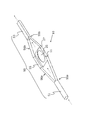
- the outer shape of the housing of the electronic device 10 having the inclined shape one having a frustum shape at the upper part (see the sixth embodiment, FIG. 15) and one having an ellipsoidal shape (seventh embodiment). , See FIG. 16) and the like.
- the first region 50 extends in the front-rear direction, application example regarding the configuration of the first region 50
- the front region 51, the center region 55, and the rear region 53 are arranged in the left-right direction (x direction)
- a first region 50 configured separately from these members is provided in a specific region of the vehicle 1 (a region between the roof 1a and the roof lining 1b).
- the front region 51, the central region 55, and the rear region 53 may be arranged in other directions (see the eighth embodiment, FIG. 17).
- the first region 50 may be integrally configured with a specific region of the vehicle 1.
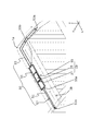
- FIG. 17 shows an example in which the front region 51, the center region 55, and the rear region 53 are arranged in the front-rear direction (y direction), and the entire region between the roof 1a and the roof lining 1b constitutes the first region 50. show.
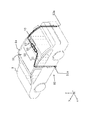
- the air from the duct 1c through which the cold air of the air conditioner 1d of the vehicle 1 flows may flow into the region where the electronic device 10 is located via the front stage region 51 (see the ninth embodiment, FIG. 18).
- the first region 50 may omit the rear region 53 and the central region 55 and have only the front region 51.
- the pre-stage region 51 may be omitted, and the air from the air supply port 51a may be directly flowed into the region where the electronic device 10 is located.
- the front region 51 communicates with each other is shown.
- the air conditioner 1d provided in the front part of the vehicle 1 (for example, the engine room)
- the front stage region 51 may communicate with the extending duct 1c.
- the front stage region 51 communicates with the duct 1c via the air supply port 51a. It is desirable that the front stage region 51 is provided with a valve 51b that controls the flow of air from the duct 1c. When the air from the duct 1c is allowed to flow in the front stage region 51, the valve 51b is opened. When the air from the duct 1c is prevented from flowing into the front stage region 51, the valve 51b is closed.
- the opening / closing control of the valve 51b is performed by an ECU (Electronic Control Unit, not shown) of the vehicle 1.
- FIG. 18 shows an example in which the valve 51b is provided in a region close to the electronic device 10 in the front stage region 51, but may be provided in the vicinity of the air supply port 51a.
- the electronic device 10 is located at a position facing the other end of the front-stage region 51 (a portion where air is discharged from the front-stage region 51), that is, at a position where cold air from the air conditioner 1d or the like passing through the front-stage region 51 is blown. , Will be placed.
- the electronic device 10 is attached to the vehicle 1 such as the roof lining 1b without going through the first region 50.
- the valve 51b When the accessory switch of the vehicle 1 is turned on, such as when the engine of the vehicle 1 is turned on, the valve 51b is set so that the air from the air conditioner 1d or the like passes through the front stage region 51 during the first time T1. It is opened. Since the valve 51b is in the open state, air from the air conditioner 1d or the like flows into the pre-stage region 51 of the first region 50 through the air supply port 51a. The air that has flowed into the pre-stage region 51 is blown onto the electronic device 10 from the other end of the pre-stage region 51.
- the air from the air conditioner 1d is allowed to flow into the pre-stage region 51 of the first region 50, and the temperature of the electronic device 10 can be adjusted at an early stage. In order to utilize the flow of air from the air conditioner 1d or the like, it is possible to allow air to flow into the pre-stage region 51 of the first region 50 without providing the fan 57.
- the configuration in which the rear region 53 and the central region 55 are omitted and air is blown from the front region 51 to the electronic device 10 is the first embodiment (air uptake from the second region 70) and the second embodiment (third region). It may be applied to (air uptake from 80).
- the electronic device 10 includes a heat radiation fin 29 having a groove provided along the flow of air.
- the direction of the groove of the heat radiation fin 29 is not limited to this.
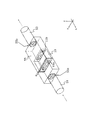
- the heat radiation fin 29 has a groove extending in a direction (y direction, z direction) perpendicular to the air flow direction (x direction) (see the tenth embodiment, FIG. 19).
- the warm air that has flowed into the air supply port 51a may flow into the region where the electronic device 10 is located via the pre-stage region 51, thereby warming the electronic device 10.
- the second region 70 corresponds to a region different from the first region 50 and having warmer air than the first region 50. From the second region 70, warm air flows into the region where the electronic device 10 of the first region 50 is located via the pre-stage region 51.
- the third region 80 corresponds to a region different from the first region 50 and having warmer air than the first region 50. From the third region 80, warm air flows into the region where the electronic device 10 of the first region 50 is located via the pre-stage region 51.
- the air conditioner 1d causes warm air to flow through the duct 1c.
- the warm air flowing through the duct 1c flows into a region of the first region 50 where the electronic device 10 is located, via the pre-stage region 51. Further, when warm air flows into a certain area of the electronic device 10, the heat absorbing / radiating member 21 is used for heat absorption, that is, for transferring the heat of the warm air to the member of the electronic device 10.
- the temperature control structure of the electronic device provided inside the vehicle includes a first region.
- the first region is a region different from the first region through the air supply port and has cold air or warm air as compared with the first region 50, and at least a duct of the air conditioner of the vehicle. Communicate with one.
- the air that has flowed into the air supply port flows into the region where the electronic device in the first region is located.
- air is taken into the first region from the second region or the like, and the taken air is used for temperature adjustment of the electronic device 10.
- the taken air is used for temperature adjustment of the electronic device 10.
- the first region has a pre-stage region including an air supply port.
- the air that has flowed into the air supply port flows into the area where the electronic device is located through the pre-stage area.
- a fan that performs at least one of inflowing air into the region where the electronic device is located and discharging air from the region where the electronic device is located is provided separately from the electronic device.
- the third aspect by using a fan, it is possible to allow air to flow into a certain region of an electronic device regardless of the pressure state in the first region.
- the temperature of the electronic device is high or low, such as the vehicle is not running, immediately before the accessory switch of the vehicle is turned on. Therefore, if the fan is operated when the accessory switch of the vehicle is turned on, it is possible to effectively adjust the temperature of the electronic device as compared with the form in which the fan is operated at other times. ..
- the housing of the electronic device has an air supply opening and an exhaust opening.
- the air that has flowed into the area where the electronic device is located flows into the inside of the housing through the air supply opening and is discharged to the outside of the housing through the exhaust opening.
- ventilation holes air supply opening, exhaust opening
- the electronic device is provided with a shielding plate for covering the mounting component mounted on the substrate and a heat absorbing / radiating member.
- the shielding plate and the heat absorbing / radiating member are integrally configured.
- the configuration of the heat absorbing / radiating member and the shielding plate can be simplified, and the heat transfer efficiency can be improved.
- the first region has a central region that houses the electronic device.
- the first end region on the upstream side of the central region has a shape in which the cross-sectional area gradually increases from the upstream side.
- the inclined portion in the region including the first end region, it is possible to make it difficult for stagnation to occur in the flow path.
- the first region communicates with the other region via the air supply port.
- the other area is the space including the driver's seat or under the floor of the vehicle.
- the other region may be located at a position lower than the first region and may be in a different temperature state from the first region. Therefore, the temperature of the electronic device can be adjusted by the air flowing in from the second region.
- the front stage region communicates with the duct through the air supply port.
- the electronic device is provided at a position facing the portion where air is discharged in the front region.
- a valve is provided to control the flow of air from the duct to the pre-stage area.
- the temperature of the electronic device can be adjusted at an early stage by inflowing cold air or warm air from the air conditioner into the first region.
- the air from the air supply port is configured to pass through the lower part of the electronic device.
- a heat absorbing / radiating member is provided in a region below the electronic device through which air from the air supply port passes.
- the temperature of the electronic device can be adjusted by flowing air taken in from the outside around the electronic device (lower surface). While preventing impurities such as dust from entering the inside of electronic devices, it is possible to adjust the temperature of electronic devices using air taken in from the outside. By cooling or warming the heat absorbing / radiating member, it becomes possible to adjust the temperature of the internal member of the electronic device.
Landscapes
- Engineering & Computer Science (AREA)
- Microelectronics & Electronic Packaging (AREA)
- Physics & Mathematics (AREA)
- Thermal Sciences (AREA)
- Electromagnetism (AREA)
- Remote Sensing (AREA)
- Cooling Or The Like Of Electrical Apparatus (AREA)
Priority Applications (3)
| Application Number | Priority Date | Filing Date | Title |
|---|---|---|---|
| US18/013,556 US20230292458A1 (en) | 2020-06-30 | 2021-06-04 | Temperature adjusting structure for electronic equipment |
| CN202180043438.6A CN115720729A (zh) | 2020-06-30 | 2021-06-04 | 电子设备的温度调节构造 |
| EP21833210.4A EP4175431A1 (en) | 2020-06-30 | 2021-06-04 | Temperature regulating structure for electronic equipment |
Applications Claiming Priority (2)
| Application Number | Priority Date | Filing Date | Title |
|---|---|---|---|
| JP2020-113447 | 2020-06-30 | ||
| JP2020113447A JP7618399B2 (ja) | 2020-06-30 | 2020-06-30 | 電子機器の温度調整構造 |
Publications (1)
| Publication Number | Publication Date |
|---|---|
| WO2022004272A1 true WO2022004272A1 (ja) | 2022-01-06 |
Family
ID=79315935
Family Applications (1)
| Application Number | Title | Priority Date | Filing Date |
|---|---|---|---|
| PCT/JP2021/021326 Ceased WO2022004272A1 (ja) | 2020-06-30 | 2021-06-04 | 電子機器の温度調整構造 |
Country Status (5)
| Country | Link |
|---|---|
| US (1) | US20230292458A1 (enExample) |
| EP (1) | EP4175431A1 (enExample) |
| JP (1) | JP7618399B2 (enExample) |
| CN (1) | CN115720729A (enExample) |
| WO (1) | WO2022004272A1 (enExample) |
Families Citing this family (4)
| Publication number | Priority date | Publication date | Assignee | Title |
|---|---|---|---|---|
| KR102707114B1 (ko) * | 2019-10-11 | 2024-09-20 | 삼성전자주식회사 | 안테나 고정 구조 및 이를 포함하는 전자 장치 |
| US20230146354A1 (en) | 2021-08-20 | 2023-05-11 | Semiconductor Energy Laboratory Co., Ltd. | Light-emitting device, light-emitting apparatus, organic compound, electronic appliance, and lighting device |
| EP4521867A1 (en) * | 2023-09-07 | 2025-03-12 | Valeo Comfort and Driving Assistance | Telematics control unit for a vehicle |
| USD1122177S1 (en) * | 2024-07-30 | 2026-04-14 | Bridgestone Europe Nv/Sa | Tire |
Citations (8)
| Publication number | Priority date | Publication date | Assignee | Title |
|---|---|---|---|---|
| JPH0531294U (ja) * | 1991-09-30 | 1993-04-23 | 日本電気株式会社 | プリント基板用ヒートシンク |
| JPH10329624A (ja) * | 1997-06-03 | 1998-12-15 | Toyota Motor Corp | 電子部品の冷却構造 |
| JP2001127475A (ja) * | 1999-10-25 | 2001-05-11 | Auto Network Gijutsu Kenkyusho:Kk | 車両の電圧変換装置および冷却装置 |
| JP2002016385A (ja) * | 2000-06-26 | 2002-01-18 | Nippon Yusoki Co Ltd | 発熱部品の放熱装置 |
| JP2003295977A (ja) * | 2003-04-18 | 2003-10-17 | Denso Corp | 車載パーソナルコンピュータの冷却方法 |
| JP2014054864A (ja) * | 2012-09-11 | 2014-03-27 | Toyota Motor Corp | 蓄電装置の冷却構造 |
| JP2019047192A (ja) | 2017-08-30 | 2019-03-22 | 株式会社ヨコオ | アンテナ装置 |
| JP2021093493A (ja) * | 2019-12-12 | 2021-06-17 | トヨタ自動車株式会社 | 電子制御装置の冷却構造及び冷却制御システム |
Family Cites Families (12)
| Publication number | Priority date | Publication date | Assignee | Title |
|---|---|---|---|---|
| JPS59122906U (ja) * | 1983-02-08 | 1984-08-18 | 株式会社ボッシュオートモーティブ システム | 車両用空気調和装置 |
| JP2005199862A (ja) * | 2004-01-15 | 2005-07-28 | Nippon Soken Inc | 車両用オーバヘッドモジュール |
| JP5131182B2 (ja) * | 2008-12-24 | 2013-01-30 | トヨタ自動車株式会社 | 蓄電モジュールの温度調節構造 |
| KR101232784B1 (ko) * | 2010-12-06 | 2013-02-13 | 주식회사 엘지화학 | 이차전지 냉각장치 및 이차전지 운전열을 이용한 난방 시스템 |
| JP5684768B2 (ja) * | 2012-09-27 | 2015-03-18 | 株式会社クボタ | 作業車 |
| US20140130932A1 (en) * | 2012-11-15 | 2014-05-15 | ProFab Metalwerkz, LLC | Methods and apparatus for universal transition |
| DE102013214071A1 (de) * | 2013-07-19 | 2015-01-22 | Bayerische Motoren Werke Aktiengesellschaft | Verfahren zum Steuern einer Lüftungs-/Klimaanlage eines Fahrzeugs sowie Fahrzeug mit einer derartigen Lüftungs-/Klimaanlage |
| JP6303030B2 (ja) * | 2015-02-05 | 2018-03-28 | 本田技研工業株式会社 | 車両のバッテリ冷却構造 |
| CN107531125B (zh) * | 2015-04-24 | 2020-04-07 | 株式会社电装 | 车辆用空调装置 |
| TWI588047B (zh) * | 2016-01-20 | 2017-06-21 | 國立雲林科技大學 | 車頂夾層抽氣散熱構造 |
| JP6999489B2 (ja) | 2018-05-10 | 2022-01-18 | 三菱電機株式会社 | アンテナ装置 |
| KR102573804B1 (ko) * | 2018-12-18 | 2023-09-01 | 현대자동차주식회사 | 통합 제어 유닛, 이를 포함하는 차량 및 그 제어 방법 |
-
2020
- 2020-06-30 JP JP2020113447A patent/JP7618399B2/ja active Active
-
2021
- 2021-06-04 CN CN202180043438.6A patent/CN115720729A/zh active Pending
- 2021-06-04 US US18/013,556 patent/US20230292458A1/en active Pending
- 2021-06-04 EP EP21833210.4A patent/EP4175431A1/en not_active Withdrawn
- 2021-06-04 WO PCT/JP2021/021326 patent/WO2022004272A1/ja not_active Ceased
Patent Citations (8)
| Publication number | Priority date | Publication date | Assignee | Title |
|---|---|---|---|---|
| JPH0531294U (ja) * | 1991-09-30 | 1993-04-23 | 日本電気株式会社 | プリント基板用ヒートシンク |
| JPH10329624A (ja) * | 1997-06-03 | 1998-12-15 | Toyota Motor Corp | 電子部品の冷却構造 |
| JP2001127475A (ja) * | 1999-10-25 | 2001-05-11 | Auto Network Gijutsu Kenkyusho:Kk | 車両の電圧変換装置および冷却装置 |
| JP2002016385A (ja) * | 2000-06-26 | 2002-01-18 | Nippon Yusoki Co Ltd | 発熱部品の放熱装置 |
| JP2003295977A (ja) * | 2003-04-18 | 2003-10-17 | Denso Corp | 車載パーソナルコンピュータの冷却方法 |
| JP2014054864A (ja) * | 2012-09-11 | 2014-03-27 | Toyota Motor Corp | 蓄電装置の冷却構造 |
| JP2019047192A (ja) | 2017-08-30 | 2019-03-22 | 株式会社ヨコオ | アンテナ装置 |
| JP2021093493A (ja) * | 2019-12-12 | 2021-06-17 | トヨタ自動車株式会社 | 電子制御装置の冷却構造及び冷却制御システム |
Also Published As
| Publication number | Publication date |
|---|---|
| JP2022011987A (ja) | 2022-01-17 |
| JP7618399B2 (ja) | 2025-01-21 |
| EP4175431A1 (en) | 2023-05-03 |
| US20230292458A1 (en) | 2023-09-14 |
| CN115720729A (zh) | 2023-02-28 |
Similar Documents
| Publication | Publication Date | Title |
|---|---|---|
| JP2022011987A (ja) | 電子機器の温度調整構造 | |
| JP7270692B2 (ja) | 車体アンテナモジュールおよび車体アンテナモジュールを冷却するための方法 | |
| CN110808443B (zh) | 一种车载天线模块和车载通信终端 | |
| US20080205001A1 (en) | Blower and air conditioner for vehicle | |
| JP6675937B2 (ja) | 熱媒体加熱装置およびこれを用いた車両用空調装置 | |
| CN108697036A (zh) | 一种适用于充电桩模块的隔离式散热结构及其散热方法 | |
| CN112352349A (zh) | 用于无线电装置的冷却系统 | |
| JP2022011987A5 (enExample) | ||
| JP2012017031A (ja) | 熱媒体加熱装置およびそれを用いた車両用空気調和装置 | |
| CN113287227A (zh) | 车辆用通信装置 | |
| JP2003110330A (ja) | アンテナ装置 | |
| US20220032729A1 (en) | Vehicle air conditioning | |
| US20210195727A1 (en) | Multi-zone heat sink for printed circuit boards | |
| CN208425101U (zh) | 一种适用于充电桩模块的隔离式散热结构 | |
| CN112607017A (zh) | 无人机 | |
| US12010821B2 (en) | Thermal diode device for a telematic control unit of a vehicle | |
| WO2024130625A1 (zh) | 散热装置、电子设备和车辆 | |
| CN216357931U (zh) | 车载装置 | |
| WO2020261655A1 (ja) | 車載用電子装置 | |
| CN114171879A (zh) | 一种散热结构、卫星通信装置及车辆 | |
| CN113677156B (zh) | 散热背夹及电子设备组件 | |
| JP2007035722A (ja) | 車載機器の放熱構造 | |
| WO2024222454A1 (zh) | 车载无线充电模组及车辆 | |
| JP2004106614A (ja) | 車両用空調機および空調機用パワーモジュール | |
| CA3114254C (en) | Battery device capable of preventing temperature increase due to hot air and travelling apparatus having same |
Legal Events
| Date | Code | Title | Description |
|---|---|---|---|
| 121 | Ep: the epo has been informed by wipo that ep was designated in this application |
Ref document number: 21833210 Country of ref document: EP Kind code of ref document: A1 |
|
| NENP | Non-entry into the national phase |
Ref country code: DE |
|
| ENP | Entry into the national phase |
Ref document number: 2021833210 Country of ref document: EP Effective date: 20230130 |