WO2022003877A1 - 搬送容器および搬送方法 - Google Patents
搬送容器および搬送方法 Download PDFInfo
- Publication number
- WO2022003877A1 WO2022003877A1 PCT/JP2020/025911 JP2020025911W WO2022003877A1 WO 2022003877 A1 WO2022003877 A1 WO 2022003877A1 JP 2020025911 W JP2020025911 W JP 2020025911W WO 2022003877 A1 WO2022003877 A1 WO 2022003877A1
- Authority
- WO
- WIPO (PCT)
- Prior art keywords
- transport container
- rib
- transport
- connecting member
- bottom member
- Prior art date
Links
- 238000000034 method Methods 0.000 title claims abstract description 81
- 239000000463 material Substances 0.000 claims description 31
- 230000003028 elevating effect Effects 0.000 claims description 21
- 230000000149 penetrating effect Effects 0.000 claims description 11
- 230000032258 transport Effects 0.000 description 294
- 238000012986 modification Methods 0.000 description 20
- 230000004048 modification Effects 0.000 description 20
- 239000000523 sample Substances 0.000 description 10
- 239000007788 liquid Substances 0.000 description 6
- 238000004458 analytical method Methods 0.000 description 4
- 239000012488 sample solution Substances 0.000 description 4
- 238000004611 spectroscopical analysis Methods 0.000 description 4
- 239000000126 substance Substances 0.000 description 4
- 239000000203 mixture Substances 0.000 description 2
- -1 polyethylene Polymers 0.000 description 2
- 229920003002 synthetic resin Polymers 0.000 description 2
- 239000000057 synthetic resin Substances 0.000 description 2
- 238000012546 transfer Methods 0.000 description 2
- 229910000838 Al alloy Inorganic materials 0.000 description 1
- 229910000975 Carbon steel Inorganic materials 0.000 description 1
- 239000004698 Polyethylene Substances 0.000 description 1
- 239000004743 Polypropylene Substances 0.000 description 1
- 239000004793 Polystyrene Substances 0.000 description 1
- NIXOWILDQLNWCW-UHFFFAOYSA-N acrylic acid group Chemical group C(C=C)(=O)O NIXOWILDQLNWCW-UHFFFAOYSA-N 0.000 description 1
- 229920000122 acrylonitrile butadiene styrene Polymers 0.000 description 1
- 238000013459 approach Methods 0.000 description 1
- 239000010962 carbon steel Substances 0.000 description 1
- 239000003153 chemical reaction reagent Substances 0.000 description 1
- 210000000078 claw Anatomy 0.000 description 1
- 238000011109 contamination Methods 0.000 description 1
- 238000012258 culturing Methods 0.000 description 1
- 230000000694 effects Effects 0.000 description 1
- 238000007689 inspection Methods 0.000 description 1
- 238000009434 installation Methods 0.000 description 1
- 239000007769 metal material Substances 0.000 description 1
- 244000052769 pathogen Species 0.000 description 1
- 230000035515 penetration Effects 0.000 description 1
- 230000002165 photosensitisation Effects 0.000 description 1
- 239000003504 photosensitizing agent Substances 0.000 description 1
- 239000004417 polycarbonate Substances 0.000 description 1
- 229920005668 polycarbonate resin Polymers 0.000 description 1
- 229920001225 polyester resin Polymers 0.000 description 1
- 229920000573 polyethylene Polymers 0.000 description 1
- 229920001155 polypropylene Polymers 0.000 description 1
- 229920002223 polystyrene Polymers 0.000 description 1
- 229920005989 resin Polymers 0.000 description 1
- 239000011347 resin Substances 0.000 description 1
- 239000004065 semiconductor Substances 0.000 description 1
- 239000010935 stainless steel Substances 0.000 description 1
- 229910001220 stainless steel Inorganic materials 0.000 description 1
- 238000012360 testing method Methods 0.000 description 1
Images


Classifications
-
- B—PERFORMING OPERATIONS; TRANSPORTING
- B65—CONVEYING; PACKING; STORING; HANDLING THIN OR FILAMENTARY MATERIAL
- B65D—CONTAINERS FOR STORAGE OR TRANSPORT OF ARTICLES OR MATERIALS, e.g. BAGS, BARRELS, BOTTLES, BOXES, CANS, CARTONS, CRATES, DRUMS, JARS, TANKS, HOPPERS, FORWARDING CONTAINERS; ACCESSORIES, CLOSURES, OR FITTINGS THEREFOR; PACKAGING ELEMENTS; PACKAGES
- B65D61/00—External frames or supports adapted to be assembled around, or applied to, articles
- B65D61/02—Tubular frames with resilient joints
-
- B—PERFORMING OPERATIONS; TRANSPORTING
- B65—CONVEYING; PACKING; STORING; HANDLING THIN OR FILAMENTARY MATERIAL
- B65D—CONTAINERS FOR STORAGE OR TRANSPORT OF ARTICLES OR MATERIALS, e.g. BAGS, BARRELS, BOTTLES, BOXES, CANS, CARTONS, CRATES, DRUMS, JARS, TANKS, HOPPERS, FORWARDING CONTAINERS; ACCESSORIES, CLOSURES, OR FITTINGS THEREFOR; PACKAGING ELEMENTS; PACKAGES
- B65D85/00—Containers, packaging elements or packages, specially adapted for particular articles or materials
- B65D85/62—Containers, packaging elements or packages, specially adapted for particular articles or materials for stacks of articles; for special arrangements of groups of articles
-
- B—PERFORMING OPERATIONS; TRANSPORTING
- B01—PHYSICAL OR CHEMICAL PROCESSES OR APPARATUS IN GENERAL
- B01L—CHEMICAL OR PHYSICAL LABORATORY APPARATUS FOR GENERAL USE
- B01L3/00—Containers or dishes for laboratory use, e.g. laboratory glassware; Droppers
- B01L3/56—Labware specially adapted for transferring fluids
-
- B—PERFORMING OPERATIONS; TRANSPORTING
- B01—PHYSICAL OR CHEMICAL PROCESSES OR APPARATUS IN GENERAL
- B01L—CHEMICAL OR PHYSICAL LABORATORY APPARATUS FOR GENERAL USE
- B01L9/00—Supporting devices; Holding devices
- B01L9/52—Supports specially adapted for flat sample carriers, e.g. for plates, slides, chips
- B01L9/523—Supports specially adapted for flat sample carriers, e.g. for plates, slides, chips for multisample carriers, e.g. used for microtitration plates
-
- B—PERFORMING OPERATIONS; TRANSPORTING
- B65—CONVEYING; PACKING; STORING; HANDLING THIN OR FILAMENTARY MATERIAL
- B65D—CONTAINERS FOR STORAGE OR TRANSPORT OF ARTICLES OR MATERIALS, e.g. BAGS, BARRELS, BOTTLES, BOXES, CANS, CARTONS, CRATES, DRUMS, JARS, TANKS, HOPPERS, FORWARDING CONTAINERS; ACCESSORIES, CLOSURES, OR FITTINGS THEREFOR; PACKAGING ELEMENTS; PACKAGES
- B65D25/00—Details of other kinds or types of rigid or semi-rigid containers
- B65D25/28—Handles
- B65D25/2802—Handles fixed, i.e. non-swingable, handles
-
- B—PERFORMING OPERATIONS; TRANSPORTING
- B65—CONVEYING; PACKING; STORING; HANDLING THIN OR FILAMENTARY MATERIAL
- B65D—CONTAINERS FOR STORAGE OR TRANSPORT OF ARTICLES OR MATERIALS, e.g. BAGS, BARRELS, BOTTLES, BOXES, CANS, CARTONS, CRATES, DRUMS, JARS, TANKS, HOPPERS, FORWARDING CONTAINERS; ACCESSORIES, CLOSURES, OR FITTINGS THEREFOR; PACKAGING ELEMENTS; PACKAGES
- B65D71/00—Bundles of articles held together by packaging elements for convenience of storage or transport, e.g. portable segregating carrier for plural receptacles such as beer cans or pop bottles; Bales of material
- B65D71/02—Arrangements of flexible binders
- B65D71/04—Arrangements of flexible binders with protecting or supporting elements arranged between binder and articles or materials, e.g. for preventing chafing of binder
-
- B—PERFORMING OPERATIONS; TRANSPORTING
- B01—PHYSICAL OR CHEMICAL PROCESSES OR APPARATUS IN GENERAL
- B01L—CHEMICAL OR PHYSICAL LABORATORY APPARATUS FOR GENERAL USE
- B01L2200/00—Solutions for specific problems relating to chemical or physical laboratory apparatus
- B01L2200/08—Ergonomic or safety aspects of handling devices
- B01L2200/087—Ergonomic aspects
-
- B—PERFORMING OPERATIONS; TRANSPORTING
- B01—PHYSICAL OR CHEMICAL PROCESSES OR APPARATUS IN GENERAL
- B01L—CHEMICAL OR PHYSICAL LABORATORY APPARATUS FOR GENERAL USE
- B01L2200/00—Solutions for specific problems relating to chemical or physical laboratory apparatus
- B01L2200/18—Transport of container or devices
- B01L2200/185—Long distance transport, e.g. mailing
-
- B—PERFORMING OPERATIONS; TRANSPORTING
- B01—PHYSICAL OR CHEMICAL PROCESSES OR APPARATUS IN GENERAL
- B01L—CHEMICAL OR PHYSICAL LABORATORY APPARATUS FOR GENERAL USE
- B01L3/00—Containers or dishes for laboratory use, e.g. laboratory glassware; Droppers
- B01L3/50—Containers for the purpose of retaining a material to be analysed, e.g. test tubes
- B01L3/508—Containers for the purpose of retaining a material to be analysed, e.g. test tubes rigid containers not provided for above
- B01L3/5085—Containers for the purpose of retaining a material to be analysed, e.g. test tubes rigid containers not provided for above for multiple samples, e.g. microtitration plates
Definitions
- the present invention relates to a transport container used for transporting transportable objects that can be stacked vertically, and a transport method for individually taking out the transported objects that are stacked and contained in the transport container.
- Microplates are widely used when quantifying and identifying large numbers of specimens.
- the microplate is made of synthetic resin or the like, and has a structure in which a large number of wells are provided on a flat plate.
- microplates have a flat lower surface, and some have a lower surface formed as an embossed recess with respect to the upper surface having wells.
- a microplate having a lower surface formed as a recess can often be fitted on a sample stage such as an analyzer or another microplate of the same type. The microplate having such a shape can be fixed on the sample stage or the microplate without misalignment.
- a perforated plate-shaped cover that can be sealed for each well, a non-perforated plate-shaped cover, a film-shaped cover, etc. may be attached.
- the plate-shaped cover is often molded into a shape that allows another microplate to be fitted or a shape that does not interfere with the other microplate.
- microplates are generally provided as a structure that can be stacked vertically.
- a sample solution containing a sample is manually dispensed into a well of a microplate using a micropipette or the like. If the place where the sample liquid is prepared or dispensed is far from the analysis place, it is necessary to transport the microplate to which the sample liquid is dispensed to the analysis place.
- Microplates that can be stacked vertically can be transported in a stacked state when the number of microplates to be analyzed at one time is large.
- the stacked microplates have a limited number of parts that can be held.
- analytical light is projected onto the microplate, and the sample solution may contain harmful substances that should not be touched, or there may be concerns about manual contamination. Therefore, it is usually recommended that the microplate have a surface other than the top surface.
- Patent Document 1 describes a container used for transporting and storing a cryobox.
- the container described in Patent Document 1 is provided with a grip portion at the upper part of the rack, and is a hand-held container.
- the storage unit for storing the cryobox is provided with a shelf-like structure for individually storing the cryobox.
- a large number of microplates into which the sample solution has been dispensed may be subjected to analysis at one time, and depending on the properties of the sample, rapid transportation may be desired. Even when a perforated plate-shaped cover or the like is attached to the microplate, the sample liquids may mix with each other, so that the microplate is a transported object that should avoid tilting and tipping as much as possible. Under such circumstances, there is a demand for a transport container capable of transporting a large amount of transported materials having a high risk of manual transport at one time, such as a microplate into which a sample liquid is dispensed.
- a container structure that can accommodate the transported products in a stacked state is desired from the viewpoint of improving work throughput. Further, when transporting a microplate or the like into which the sample liquid has been dispensed, there is a risk that the sample liquids may mix with each other due to tilting or tipping over, so a container structure that keeps the laminated state stable is also desired.
- the transport container not only accommodates the transported items in a laminated state, but also has a container structure that makes it easy to put in and take out the transported items with a machine or an instrument. Since the container structure described in Patent Document 1 has a shelf-like structure in which the conveyed items are individually stored, there is a problem that the conveyed container easily interferes with the machine or the appliance, and it becomes difficult to put in or take out the container by the machine or the appliance. ..
- the present invention provides a transport container capable of easily loading and unloading transportable objects and efficiently transporting vertically stackable transportable objects, and a transport method using the same.
- the purpose is.
- the transport container according to the present invention is a transport container used for transporting a transported object, and the bottom member on which the transported object is placed and the left and right arranged on the side of the bottom member.
- Side member a handle member arranged above the bottom member, left and right lower connecting members connecting the bottom member and the side member, and connecting between the side member and the handle member.
- the bottom member and the lower connecting member, the lower connecting member and the side member, the side member and the upper connecting member, and the upper connecting member and the handle member are provided with left and right upper connecting members.
- left and right hinges having rotation axes parallel and horizontal to the left and right side surfaces of the bottom member, respectively, and when the handle member is not lifted, the lower connecting member and the upper connecting member are connected to each other. Is in a sideways state non-parallel to the side member, and when the side member is separated from the bottom member and the handle member is lifted, the lower connecting member and the upper connecting member are in an upright state. , The side member is close to the bottom member and supports the conveyed object placed on the bottom member from the side.
- the transport method according to the present invention is a transport method for individually taking out the transport items stacked vertically and stored in the transport container, which is a transport container used for transporting the transport items, and the conveyed items are mounted on the transport container.
- a transport container used for transporting the transport items, and the conveyed items are mounted on the transport container.
- the lower connecting member and the left and right upper connecting members for connecting between the side member and the handle member are provided, and the bottom member and the lower connecting member, the lower connecting member and the side member, and the side member are provided.
- the upper connecting member, and the upper connecting member and the handle member are connected to each other via left and right hinges having rotation axes parallel and horizontal to the left and right side surfaces of the bottom member, respectively.
- the handle member When the handle member is not lifted, the lower connecting member and the upper connecting member are in a sideways state non-parallel to the side member, the side member is separated from the bottom member, and the handle member is separated.
- the lower connecting member and the upper connecting member are in an upright state, and the side member is close to the bottom member and supports the conveyed object placed on the bottom member from the side.
- the transport container is unloaded so that the lower connecting member and the upper connecting member are in a sideways state non-parallel to the side member.
- the transported object which is installed in a place and placed on the bottom member, is taken out from the front or the rear between the left and right side members.
- a transport container capable of easily loading and unloading transportable objects and efficiently transporting transportable objects that can be stacked vertically, and a transport method using the same. Can be done.
- FIG. 1 is a perspective view showing a transport container according to an embodiment of the present invention.
- FIG. 2 is a front view showing a transport container according to an embodiment of the present invention.
- FIG. 3 is a plan view showing a transport container according to an embodiment of the present invention.
- FIGS. 1, 2 and 3 show a state in which the conveyed container is not accommodated and is not carried by hand and is in a grounded state as viewed from each direction.
- the transport container 100 includes a bottom member 2, left and right side members 3, 3 and a handle member 4, and left and right lower connecting members 5, 5. And the left and right upper connecting members 6 and 6.
- the side member 3, the lower connecting member 5, and the upper connecting member 6 are provided symmetrically in the left-right direction of the transport container 100.
- the transport container 100 is mainly used for transporting a transported object that can be stacked vertically.
- the transport container 100 is a container for transport that accommodates a plurality of transport objects in a state of being stacked one above the other and enables transport of a large amount at one time.
- the transport container 100 can lift the handle member 4 and transport it by carrying it by hand.
- the transport container 100 may be lifted and transported by a machine or an instrument instead of a human hand as long as the handle member 4 is in a lifted state.
- an object having a rectangular outer shape in the cross section is preferable.
- the shape of the transported object may be, for example, a plate shape, a block shape, a frame shape, a dish shape, or the like.
- the conveyed objects that can be stacked vertically the upper surface side and the lower surface side can be fitted to each other, and the relative positions in the horizontal direction are fixed when they are laminated to each other, or the horizontal direction when they are laminated to each other. Some of the relative positions are not fixed. Any of these may be used as the transported object to be transported by the transport container 100.
- the transport container 100 has a substantially rectangular parallelepiped appearance.
- a bottom member 2 is arranged at the bottom of the transport container 100.
- Side members 3 are arranged on the right side portion and the left side portion of the transport container 100, respectively.
- a handle member 4 is arranged on the ceiling of the transport container 100.
- the front and rear parts of the transport container 100 are open so that the transportable material can be taken in and out.
- the bottom member 2 is a portion on which the conveyed object is placed, and when the conveyed object that can be stacked vertically is conveyed, the conveyed object is vertically laminated on the bottom member 2. It will be placed.
- the bottom member 2 is provided as a substantially rectangular parallelepiped member having a flat upper surface.
- the length of the bottom member 2 in the front-rear direction and the length in the left-right direction are such that the bottom member 2 and the transported object (see reference numeral 1 in FIG. 4) substantially overlap each other in the plan view of the transport container 100. It is provided to the same extent as the length and width.
- the left and right side members 3 are arranged on the left and right sides of the bottom member 2, respectively.
- the side member 3 is provided as a thin plate having a flat main surface.
- the left and right side members 3 are arranged in an upright state with their main surfaces facing left and right so as to face each other.
- the vertical length of the side member 3 is provided sufficiently long with respect to the thickness of the conveyed object so that the laminated conveyed object can be accommodated between the bottom member 2 and the handle member 4.
- the length of the side member 3 in the front-rear direction is provided to be about the same as the length of the bottom member 2 in the front-rear direction.
- the handle member 4 is arranged above the bottom member 2.
- the handle member 4 is provided as a thin plate material in which a handle for carrying the transport container 100 is integrated.
- the handle member 4 is arranged so as to bridge between the left and right side members 3.
- the length in the front-rear direction and the length in the left-right direction of the handle member 4 are provided to be about the same as the length in the front-rear direction and the length in the left-right direction of the bottom member 2, respectively.
- the left and right lower connecting members 5 connect between the bottom member 2 and the side member 3.
- the lower connecting member 5 is provided as a thin plate material.
- the lower connecting member 5 on the right side connects the lower end of the right side surface of the bottom member 2 and the lower end of the right side member 3 with a flat surface made of a plate material.
- the lower connecting member 5 on the left side connects the lower end of the left side surface of the bottom member 2 and the lower end of the left side member 3 with a flat surface made of a plate material.
- the length of the lower connecting member 5 in the front-rear direction is provided to be approximately the same as the length of the bottom member 2 in the front-rear direction and the length of the side member 3 in the front-rear direction.
- the left and right upper connecting members 6 are connected between the side member 3 and the handle member 4.
- the upper connecting member 6 is provided as a thin plate material.
- the upper connecting member 6 on the right side connects the upper end of the side member 3 on the right side and the right end of the handle member 4 on a flat surface made of a plate material.
- the left upper connecting member 6 connects the upper end of the left side member 3 and the left end of the handle member 4 by a flat surface made of a plate material.
- the length of the upper connecting member 6 in the front-rear direction is provided to be approximately the same as the length of the side member 3 in the front-rear direction and the length of the handle member 4 in the front-rear direction.
- the bottom member 2, the left and right side members 3, the handle member 4, the left and right lower connecting members 5, and the left and right upper connecting members 6 are made of various metal materials such as aluminum alloy, stainless steel, and carbon steel, and acrylic, respectively. It can be formed of various synthetic resin materials such as resin, polystyrene, polyethylene, polypropylene, polyester, polycarbonate and ABS resin.
- FIG. 4 is a perspective view showing a state of the transport container according to the embodiment of the present invention when the transported object is housed and is in contact with the ground.
- FIG. 5 is a perspective view showing a state of the transport container according to the embodiment of the present invention at the time of transport. 4 and 5 show a state in which the plate-shaped transported objects indicated by reference numerals 1 are stacked and accommodated in the transport container 100 shown in FIGS. 1 to 3.
- the transport container 100 is a variable container whose shape changes in conjunction with the lifting of the handle member 4. As shown in FIG. 4, the transport container 100 is in a state where the transported object can be taken in and out when the handle member 4 is not lifted. On the other hand, as shown by the arrow, when the handle member 4 is lifted, as shown in FIG. 5, the transported object contained in the transport container 100 is in a state of being supported from the surroundings.
- the bottom member 2 and the left and right lower connecting members 5, the lower connecting member 5 and the side member 3, the side member 3 and the upper connecting member 6, and the left and right upper connecting members 6 and the handle member 4 are respectively via hinges 10. They are connected to each other. The angle of connection between the members changes with the hinge 10 as the fulcrum axis.
- the hinge 10 is provided parallel to each other along the side extending in the front-rear direction between the members, and has a rotation axis arranged parallel and horizontally with respect to the left and right side surfaces of the bottom member 2. That is, the hinge 10 has a rotation axis parallel to the center line in the left-right direction extending in the front-rear direction of the bottom member 2 and the center line in the left-right direction extending in the front-rear direction of the transport container 100.
- the rotation shaft of the hinge 10 is rotatably supported by a cylindrical support portion provided on each member.
- the support portion of the hinge 10 is integrally provided for each member. With such a structure, the number of parts of the transport container 100 can be reduced. Further, it is possible to form a container structure in which the hinge 10 and each member are less likely to interfere with each other.
- the support portion of the hinge 10 may be provided as a separate body for each member. The separate support portion can be fixed to each member with screws or the like.
- the lower end of the right side surface of the bottom member 2 and the inner end of the lower right lower connecting member 5 are connected via a hinge 10 on the lower right bottom member side.
- the hinge 10 is provided so that one support portion is provided along the lower end of the right side surface of the bottom member 2, and the other support portion is provided along the inner end of the lower right side connecting member 5.
- the hinge 10 on the lower right bottom member side rotates so that the outer angle between the bottom member 2 and the lower right lower connecting member 5 is about 180 degrees to about 90 degrees, and the handle When the member 4 is released, it rotates in the opposite direction.
- the hinge 10 on the bottom member side of the lower right allows the lower connecting member 5 on the right side to be placed at an arbitrary angle between a substantially horizontal lying state (see FIG. 4) and a substantially vertical standing state (see FIG. 5). Can be operated.
- the lower end of the left side surface of the bottom member 2 and the inner end of the lower left side connecting member 5 are connected via a hinge 10 on the bottom member side of the lower left side.
- the hinge 10 on the bottom member side at the lower left is provided symmetrically with the hinge 10 on the bottom member side at the lower right.
- the hinge 10 on the bottom member side of the lower left can operate the lower connecting member 5 on the left side symmetrically with the right side.
- the outer end of the lower right lower connecting member 5 and the lower end of the right side member 3 are connected via a hinge 10 on the lower right side member side.
- the hinge 10 is provided so that one support portion is provided along the outer end of the lower right side member 5 and the other support portion is provided along the lower end of the right side member 3. ..
- the hinge 10 on the lower right side member rotates so that the internal angle between the lower right lower connecting member 5 and the right side member 3 is about 90 degrees to about 180 degrees.
- the handle member 4 When the handle member 4 is released, it rotates in the opposite direction.
- the hinge 10 on the lower right side member side keeps the right side member 3 in a substantially vertical upright state, and the right lower connecting member 5 is in a laterally tilted state that is substantially horizontal and non-parallel to the side member 3. It can be operated at any angle between (see FIG. 4) and a substantially vertical standing state (see FIG. 5).
- the outer end of the left lower connecting member 5 and the lower end of the left side member 3 are connected via a hinge 10 on the left lower side member side.
- the hinge 10 on the lower left side member side is provided symmetrically with the hinge 10 on the lower right side member side.
- the hinge 10 on the lower left side member side can operate the left side member 3 and the left lower connecting member 5 symmetrically with the right side.
- the upper end of the right side member 3 and the outer end of the right upper connecting member 6 are connected via a hinge 10 on the upper right side member side.
- the hinge 10 is provided so that one support portion is provided along the upper end of the right side member 3 and the other support portion is provided along the outer end of the right upper connecting member 6. ..
- the hinge 10 on the upper right side member is rotated so that the internal angle between the right side member 3 and the right upper connecting member 6 is about 90 degrees to about 180 degrees, and the handle member 4 is released. , Rotates in the opposite direction.
- the hinge 10 on the right upper side member side keeps the right side member 3 in a substantially vertical upright state, while the right upper connecting member 6 is in a substantially horizontal and non-parallel sideways state with respect to the side member 3. It can be operated at any angle between (see FIG. 4) and a substantially vertical standing state (see FIG. 5).
- the upper end of the left side member 3 and the outer end of the left upper connecting member 6 are connected via a hinge 10 on the upper left side member side.
- the hinge 10 on the side member side in the upper left portion is provided symmetrically with the hinge 10 on the side member side in the upper right portion.
- the hinge 10 on the left upper side member side can operate the left side member 3 and the left upper connecting member 6 symmetrically with the right side.
- the inner end of the upper connecting member 6 on the right side and the right end of the handle member 4 are connected via a hinge 10 on the handle member side in the upper right portion.
- the hinge 10 on the handle member side is provided so that one support portion is provided along the inner end of the upper connecting member 6 on the right side, and the other support portion is provided along the right end of the handle member 4. ing.
- the hinge 10 on the right upper handle member side rotates so that the outer angle between the right upper connecting member 6 and the handle member 4 is about 180 degrees to about 90 degrees, and when the handle member 4 is released, the opposite is true. Rotates to.
- the hinge 10 on the handle member side on the upper right side has the upper connecting member 6 on the right side in a laterally tilted state (see FIG. 4) that is substantially horizontal and non-parallel to the side member 3 (see FIG. 4) and an upright state that is substantially vertical (see FIG. 5). Can be operated with.
- the inner end of the upper connecting member 6 on the left side and the left end of the handle member 4 are connected via a hinge 10 on the handle member side in the upper left portion.
- the hinge 10 on the handle member side in the upper left is provided symmetrically with the hinge 10 on the handle member side in the upper right.
- the hinge 10 on the handle member side on the upper left side can operate the side member 3 on the left side and the upper connecting member 6 on the left side symmetrically with the right side.
- the left and right side members 3 move above the bottom member 2 by the hinge 10 and approach the bottom member 2 from the outside in the left-right direction.
- the side member 3 moves to the center side in the left-right direction and is arranged on the lower connecting member 5 in an upright state so as to be coplanar.
- the front opening and the rear opening of the transport container 100 are narrowed to the length in the left-right direction of the bottom member 2, and in the plan view of the transport container 100, the left and right side ends of the bottom member 2 and the left and right side members 3 are substantially abbreviated. It will be in an overlapping state. In such a state, the side member 3 can support the conveyed object placed on the bottom member 2 from the side.
- the side member 3 can align the stacked conveyed objects in the left-right direction and prevent the conveyed objects being conveyed from falling off in the left-right direction. Further, since the inner ends of the left and right lower connecting members 5 are connected to the side surface of the bottom member 2 via the hinge 10, the left and right lower connecting members 5 are in a state of surface contact with the left and right side surfaces of the bottom member 2. In such a state, the rotation angle of the hinge 10 at the inner end of the left and right lower connecting members 5 is limited. Therefore, it is possible to suppress the deflection of the entire structure of the transport container 100 and reduce the shaking of the transported object laminated on the bottom member 2.
- the transport container 100 has ribs extending inward in the left-right direction from the front ends and the rear ends of the left and right side members 3 at the front and rear ends of the left and right side members 3, respectively. 7 is provided.
- the ribs 7 are provided as thin rectangular parallelepiped pieces at the front and rear ends of the right side member 3 and the front and rear ends of the left side member 3.
- the rib 7 extends inward in the left-right direction from each of the front end and the rear end of the left and right side members 3.
- the left and right side members 3 are close to the bottom member 2 from the outside in the left-right direction and are coplanar on the lower connecting member 5 in the upright state.
- the front end and the rear end of the bottom member 2 and the rib 7 are substantially overlapped with each other.
- the rib 7 can support the conveyed object placed on the bottom member 2 from the front and the rear. Therefore, the ribs 7 can align the stacked conveyed objects in the front-rear direction and prevent the conveyed objects being conveyed from falling off in the front-rear direction.
- the rib 7 is provided so that the angle formed by the side member 3 is substantially a right angle in the plan view of the transport container 100.
- the vertical length of the rib 7 is provided to be about the same as the vertical length of the side member 3.
- the length of the rib 7 in the left-right direction is shorter than half the length of the bottom member 2 in the left-right direction.
- FIG. 6 is an enlarged perspective view showing the lower end portion of the transport container according to the embodiment of the present invention.
- the rib 7 is provided in a shape protruding downward from the lower end of the side member 3. Further, it is preferable that the rib 7 projecting downward is provided in a shape having a horizontal lower end.
- the rib 7 is provided as a thin plate piece having a substantially rectangular parallelepiped shape, and the lower end of the rib 7 is horizontally formed substantially parallel to the ground plane of the transport container 1000. Since the lower end of the rib 7 protrudes below the lower end of the side member 3, the side member 3 stands upright by the rib 7 without directly touching the ground.
- each of the left and right side members 3 can be made to stand on its own with the rib 7 as a support leg when the handle member 4 is not lifted. Even when the upper connecting member 6 and the handle member 4 wobble in the left-right direction, the transport container 100 in a grounded state in which the handle member 4 is not lifted can be made to stand on its own, so that the transported object can be easily taken in and out. It can be carried out.
- the rib 7 is appropriately supported as long as the side member 3 is supported by one or more points on each of the front end side and the rear end side of the side member 3.
- the side member 3 is formed by the inside of the lower end of the rib 7 in the left-right direction and the lower end of the side member 3.
- FIG. 7 is a plan view showing a transport container according to a modified example of the present invention.
- the transport container used for transporting the transported object is provided so that the angle formed by the side member 3 (inner angle indicated by ⁇ in FIG. 7) is an obtuse angle in the plan view of the transport container. It can also be in the form of a rib 7 (conveyor container 200).
- the rib 7 is provided as a thin plate piece at the front end and the rear end of the right side member 3 and at the front end and the rear end of the left side member 3.
- the internal angle between the rib 7 and the side member 3 is 90 degrees or more, and the inside of the rib 7 in the left-right direction is open to the outside in the front-rear direction.
- the conveyed object placed on the bottom member 2 can be aligned by using the rib 7 as a guide.
- the rib 7 moves inward in the left-right direction, so that the conveyed object protruding from the bottom member 2 is guided in the front-rear direction along the rib 7.
- the conveyed objects can be automatically aligned in conjunction with the lifting of the handle member 4, so that the risk and labor due to manual work can be reduced. can.
- FIG. 8 is a perspective view showing a state at the time of touchdown in which the transported object of the transport container according to the modified example of the present invention is housed.
- FIG. 9 is a perspective view showing a state of the transport container according to the modified example of the present invention at the time of transport.
- the side member 3 and the upper connecting member 6 of the transport container 100 have fasteners 51 and 52 for locking the upper connecting member 6 in the upright state to the side member 3 in the upright state. Can be provided.
- the fasteners 51 and 52 include a hook 51 and a stud 52 with a cap that can lock the hook 51.
- the hook 51 is rotatably supported by a shaft fixed to the outer surface of the upper connecting member 6 on the right side.
- the stud 52 is fixed to the upper side of the outer surface of the right side member 3.
- the hook 51 can be hooked on the stud 52 by rotating it around an axis when the upper connecting member 6 is in an upright state substantially parallel to the side member 3.
- the hook 51 locked to the stud 52 supports the upper connecting member 6 so as not to fall, and works to keep the upper connecting member 6 and the side member 3 in a substantially parallel state. Since the stud 52 has a cap, the hook 51 does not come off to the outside even if the upper connecting member 6 tries to fall.
- the hook 51 can be removed from the stud 52 by rotating it in the opposite direction.
- the hook 51 is provided on the outer surface of the upper connecting member 6, and the stud 52 is provided on the outer surface of the side member 3.
- the member 3 may be provided with a hook 51
- the upper connecting member 6 may be provided with a stud 52.
- the fasteners 51 and 52 may be provided on the inner surface of each member instead of the outer surface of each member.
- fasteners 51 and 52 may be provided on other members whose orientation changes in association with the lifting of the handle member 4.
- the movable side of the fasteners 51 and 52 can be provided on the left and right lower connecting members 5 or the left and right side members 3, or the left and right side members 3 or the left and right upper connecting members 6.
- the fixed side of the fasteners 51 and 52 can be provided on the paired members.
- the hook can be used instead of the hook 51 and the stud 52.
- a tilt stopper that is caught in the hole, a slide type latch, a lever type latch, a push type latch, a box type latch, or the like may be used.
- the places where the fasteners 51 and 52 are provided may be one place or a plurality of places per 100 transport containers.
- FIGS. 10 to 21 show a transport method in which transport items stacked vertically and stored in a transport container are individually taken out and transported to a target place.
- the transport method shown in each figure is particularly characterized by the unloading process.
- an autoloader that automatically unloads the transported material is used for the work of taking out the transported material from the transport container.
- the transport container shown in each figure is provided with a structure corresponding to an autoloader.
- FIGS. 10 to 17 show a method of individually taking out the transported items stacked vertically and stored in the transport container from the lower stage side.
- the autoloader has a movable stage (elevating means for the transported object) 61 for lifting the entire conveyed object mounted on the bottom member 2a, and a stage lift 62 for raising and lowering the movable stage 61 up and down.
- a fort (elevating means for the transported object) 63 for lifting the stacked transported objects, and a drawer (drawing means for the transported object) 64 for horizontally pulling out the transported object are provided.
- a pedestal-shaped bottom member 2a is provided at the bottom of the transport container in place of the substantially rectangular parallelepiped bottom member 2 (see FIG. 2 and the like).
- the gantry-shaped bottom member 2a is provided in a frame-shaped structure that supports only the outer edge portion of the lower surface of the conveyed object in the left-right direction.
- the gantry-shaped bottom member 2a has a penetration structure penetrating in the vertical direction for inserting the movable stage 61 from below the transported object placed on the bottom member 2a, and the drawer 64 is inserted from the front-rear direction of the bottom member 2a. It has a penetrating structure that penetrates in the front-back direction. Further, the movable stage 61 has a penetrating structure penetrating in the front-rear direction for inserting the drawer 64.
- side members 3A having through holes 31, 32, 33, 34 on the left and right side portions of the transport container instead of the side members 3 (see FIG. 1 and the like), 3B, 3C, 3D are provided.
- the side members 3A, 3B, 3C, and 3D have through holes 31, 32, 33, and 34 for inserting a fork (elevating means for the transported object) 63 for raising and lowering the transported object between the stacked transported objects. Is on the lower side of the main surface.
- the through holes 31, 32, 33, and 34 are provided in each of the left and right side members 3A, 3B, 3C, and 3D in a horizontally long slit shape so as to have the same height as each other.
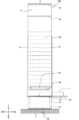
- FIG. 10 is a front view of a transport container showing an example of a take-out method used for the transport container according to the modified example of the present invention.
- FIG. 11 is a side view of a transport container showing an example of a take-out method used for the transport container according to the modified example of the present invention. 10 and 11 show a method of individually taking out the conveyed items stacked vertically and contained in the conveyed container 300 from the lower stage side at a substantially horizontal taking-out place.
- the left and right side members 3A are provided with through holes 31 at predetermined heights.
- the left and right through holes 31 are provided so as to be located near the second step from the bottom, which is higher than the upper end of the bottom member 2a and the conveyed object at the bottom step when the handle member 4 is not lifted.
- the left and right lower connecting members 5 and the left and right upper connecting members 6 are attached to the left and right side members 3A in the transport container 300 in which the conveyed objects are stacked and stored vertically. It is installed in a substantially horizontal take-out place 60 so as to be in a non-parallel sideways state. Since the front opening and the rear opening of the transport container 300 are widened to the maximum to the left and right, the space above the bottom member 2a is widely opened.
- the entire conveyed object placed on the bottom member 2a is placed up to a height at which the fork 63 can be inserted through the through hole 31 between the lowermost conveyed object and the second-stage conveyed object.
- Lifted by the movable stage 61 If the height of the through hole 31 is appropriately designed in advance according to the height of the transported object, this operation may not be performed.
- a substantially rectangular parallelepiped bottom member 2 (see FIG. 2 and the like) may be used instead of the gantry-shaped bottom member 2a.
- the fork 63 is inserted through the through hole 31 between the lowermost transported object and the second-stage conveyed object from the bottom, and the second-stage and subsequent conveyed objects are lifted by the fork 63.
- the bottom transports can be individually loaded and unloaded in the front-rear direction of the transport container 300.
- the fork 63 is provided in an inclined shape in which the base end side is higher in the side view, but the shape and mechanism of the elevating means for the conveyed object can lift the conveyed object through the through hole 31.
- the lifting means for the transported object may itself be one that moves up and down to lift the transported object.
- the drawer 64 is inserted under the lowermost conveyed object, and the lowermost conveyed object is taken out from between the left and right side members 3A.
- the drawer 64 is inserted from the rear of the transport container 300 and is configured to pull out the transported object to the rear, but is inserted from the front of the transport container 300 and is configured to pull out the transported object to the front. You may.
- the drawer 64 is provided in the shape of a claw whose tip side is bent upward in a side view, but the shape and mechanism of the taking-out means for the conveyed object take out the conveyed object in a substantially horizontal direction. As long as it can be done, it is not particularly limited.
- the taking-out means for the conveyed object may be a mechanism for pulling out the conveyed object or a mechanism for pushing out the conveyed object to a tray or the like.
- the fork 63 After taking out the transported object in the lowermost stage, the fork 63 is pulled out to the outside, and the transported object in the second stage from the bottom is placed on the bottom member 2a. After that, the process of taking out the transported object in the lowest stage is repeated, with the transported object in the second stage from the bottom as the transported object in the lowest stage.
- the transported items taken out from the transport container 300 can be individually transported to a target place.
- an elevating means for transports and an take-out means for transports are used, so that the transports stacked vertically and stored in the transport container are automatically individually individually. Can be taken out.
- the transport container By simply installing the transport container at a predetermined take-out location, the stacked and stored transport items can be individually taken out, so that the risk and labor of manual work can be reduced.
- the movable stage 61 and the stage lift 62 need only be a small device that aligns the heights of the conveyed objects. If the height of the through hole 31 is appropriately designed in advance according to the height of the transported object, the installation of the movable stage 61 and the stage lift 62 can be omitted. Therefore, the cost can be suppressed by providing the autoloader in a simple structure.
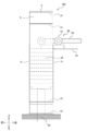
- FIG. 12 is a front view of a transport container showing an example of a take-out method used for the transport container according to the modified example of the present invention.
- FIG. 13 is a side view of a transport container showing an example of a take-out method used for the transport container according to the modified example of the present invention. 12 and 13 show a method of individually taking out the conveyed items stacked vertically and stored in the conveyed container 400 from the lower stage side at the taking-out place provided with the inclined guide.
- the left and right side members 3B are provided with through holes 32 at predetermined heights.
- the left and right through holes 32 are at a lower position than the lowermost conveyed object when the handle member 4 is not lifted, and when the handle member 4 is lifted to a medium height, that is, the left and right lower connecting members 5
- the left and right upper connecting members 6 are in an inclined state non-parallel to the left and right side members 3B, they are provided so as to be at a position near the second stage from the bottom, which is higher than the transported object at the bottom stage. ing.
- the left and right lower connecting members 5 and the left and right upper connecting members 6 are attached to the left and right side members 3B in the transport container 400 in which the conveyed objects are stacked and stored vertically. It is installed in the take-out place 60 provided with the inclination guide 65 so as to be in a non-parallel inclined state, and the lowermost conveyed object is exposed from between the left and right side members 3B.
- the front opening and the rear opening of the transport container 400 expand to the left and right to the extent that the front and rear surfaces of the transport object are not covered with the ribs 7, so that the space above the bottom member 2a is open. However, the width as a whole is suppressed according to the angle of inclination.
- the upper surface of the tilt guide 65 is slanted, and the tilt guide 65 is fixed symmetrically so that the outside is higher on the left and right of the take-out location 60.
- the tilt guides 65 are arranged at intervals similar to the length of the bottom member 2a in the left-right direction so that the slanted upper surfaces of the lower left and right lower connecting members 5 come into surface contact with each other.
- the angle of inclination of the inclination guide 65 is not particularly limited as long as the front surface and the rear surface of the conveyed object are not covered with the rib 7 when the transport container 400 is installed.
- the angle of inclination of the inclination guide 65 is preferably 45 degrees or more, more preferably 60 degrees or more, still more preferably 75 degrees or more, from the viewpoint of reducing the footprint of the transport container 400.
- the entire conveyed object placed on the bottom member 2a is moved to a height at which the fork 63 can be inserted through the through hole 32 between the lowermost conveyed object and the second-stage conveyed object. Lifted by the movable stage 61. If the height of the through hole 32 is appropriately designed in advance according to the height of the transported object, this operation may not be performed. When this operation is not performed, a substantially rectangular parallelepiped bottom member 2 (see FIG. 2 and the like) may be used instead of the gantry-shaped bottom member 2a.
- the fork 63 is inserted through the through hole 32 between the lowermost transported object and the second-stage conveyed object from the bottom, and the second-stage and subsequent conveyed objects are lifted by the fork 63.
- the bottom transports can be individually loaded and unloaded in the front-rear direction of the transport container 400.
- the drawer 64 is inserted under the lowermost conveyed object, and the lowermost conveyed object is taken out from between the left and right side members 3B.
- the drawer 64 is inserted from the rear of the transport container 400 and is configured to pull out the transported object to the rear, but is inserted from the front of the transport container 400 and is configured to pull out the transported object to the front. You may.
- the fork 63 After taking out the transported object in the lowermost stage, the fork 63 is pulled out to the outside, and the transported object in the second stage from the bottom is placed on the bottom member 2a. After that, the process of taking out the transported object in the lowest stage is repeated, with the transported object in the second stage from the bottom as the transported object in the lowest stage.
- the transported items taken out from the transport container 400 can be individually transported to a target place.
- an elevating means for transports and an take-out means for transports are used, so that the transports stacked vertically and stored in the transport container are automatically individually individually. Can be taken out.
- the transport container By simply installing the transport container at the take-out location where a predetermined tilt guide is provided, the left and right lower connecting members 5 and the left and right upper connecting members 6 are tilted in a non-parallel manner with respect to the left and right side members 3B. The risk and effort of manual work can be reduced. Further, since the openings on the front side and the rear side of the transport container 400 can be narrowed to take out the transported object, the footprint of the transport container 400 at the time of unloading can be made smaller than that of the transport container 300. can.
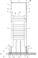
- FIG. 14 is a front view of a transport container showing an example of a take-out method used for the transport container according to the modified example of the present invention.
- FIG. 15 is a side view of a transport container showing an example of a take-out method used for the transport container according to the modified example of the present invention. 14 and 15 show a method of individually taking out the conveyed objects stacked in the upper and lower layers and stored in the transport container 500 from the lower stage side at the taking-out place provided with the inclined guide.
- the left and right side members 3C are provided with through holes 33 at predetermined heights.
- the left and right through holes 33 are positioned lower than the lowermost conveyed object when the handle member 4 is not lifted, and when the handle member 4 is lifted to a height slightly lower than the maximum, that is, the lower left and right sides.
- the connecting member 5 and the left and right upper connecting members 6 are in an inclined state close to parallel to the left and right side members 3C, the positions are higher than the transported object in the lowermost stage and are located near the second stage from the bottom. It is provided in.
- the ribs 7a provided on the left and right side members 3C are provided with a notch 71 at the lower end portion, and the inside of the lower end portion in the left-right direction is notched.
- the left and right ribs 7a have a shape that exposes the lowermost conveyed object from the portion where the rib 7a between the left and right side members 3C is cut out when the handle member 4 is lifted to a height slightly lower than the maximum. It has become.
- the lowermost conveyed object is covered with the outside of the notch 71 when the handle member 4 is lifted to the maximum height.
- the handle member 4 is lifted to a height slightly lower than the maximum, the second and subsequent items to be transported from the bottom are covered with the ribs 7a.
- the left and right lower connecting members 5 and the left and right upper connecting members 6 are attached to the left and right side members 3C in the transport container 500 in which the conveyed objects are stacked and stored vertically. It is installed in the take-out place 60 provided with the inclination guide 66 so as to be in a non-parallel inclined state, and the lowermost conveyed object is placed from the portion where the rib 7a between the left and right side members 3C is cut out. Expose.
- the front opening and the rear opening of the transport container 500 are narrowed to the left and right according to the width of the notch 71, the front and rear surfaces of the lowermost transport object are not covered with the ribs 7a, but the first from the bottom.
- the front surface and the rear surface of the second-stage conveyed object are covered with the ribs 7a, and the width as a whole is suppressed according to the angle of inclination and the width of the notch portion 71.
- the upper surface of the tilt guide 66 is slanted, and the tilt guide 66 is fixed symmetrically so that the outside is higher on the left and right of the take-out location 60.
- the tilt guides 66 are arranged at intervals comparable to the length of the bottom member 2a in the left-right direction so that the slanted upper surfaces of the left and right lower connecting members 5 come into surface contact with each other.
- the angle of inclination of the inclination guide 66 is not particularly limited as long as the front surface and the rear surface of the lowermost conveyed object are not covered with the rib 7a when the transport container 500 is installed.
- the angle of inclination of the inclination guide 66 is preferably 45 degrees or more, more preferably 60 degrees or more, still more preferably 75 degrees or more, from the viewpoint of reducing the footprint of the transport container 500.
- the entire transported object placed on the bottom member 2a is lifted by the movable stage 61, if necessary.
- the items to be conveyed in the second and subsequent stages are lifted by the fork 63.
- the drawer 64 is inserted under the lowermost conveyed object, and the rib 7a between the left and right side members 3C cuts out the lowermost conveyed object. Remove from the damaged part.
- the step of taking out the transported object in the lowest stage is repeated, with the conveyed object in the second stage from the bottom as the lowermost conveyed object.
- an elevating means for transports and an take-out means for transports are used, so that the transports stacked vertically and stored in the transport container are automatically individually individually. Can be taken out.
- the transport container By simply installing the transport container at the take-out location where a predetermined tilt guide is provided, the left and right lower connecting members 5 and the left and right upper connecting members 6 are tilted in a non-parallel manner with respect to the left and right side members 3C. The risk and effort of manual work can be reduced.
- the notch 71 is provided at the lower end of the rib 7a and the openings on the front side and the rear side of the transport container 500 can be narrowed to take out the transported material, the footprint of the transport container 500 at the time of unloading can be taken out. Can be further reduced as compared with the case of the transport container 400. Further, during unloading, the front side and the rear side of the transported object from the second stage onward from the bottom can continue to be supported by the ribs 7a.
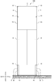
- FIG. 16 is a front view of a transport container showing an example of a take-out method used for the transport container according to the modified example of the present invention.
- FIG. 17 is a side view of a transport container showing an example of a take-out method used for the transport container according to the modified example of the present invention. 16 and 17 show a method of individually taking out the conveyed objects stacked vertically and stored in the transport container 600 from the lower stage side at the taking-out place provided with the vertical guide. In this method, as the conveyed object, one that can be fitted to each other on the upper surface side and the lower surface side and whose relative position in the horizontal direction is fixed in a state of being laminated with each other is used.
- the left and right side members 3D are provided with through holes 34 at a predetermined height.
- the left and right through holes 34 are at lower positions than the lowermost conveyed object when the handle member 4 is not lifted or when the handle member 4 is lifted to a medium height, and the handle member 4 is set to the maximum height.
- When lifted up to that point that is, when the left and right lower connecting members 5 and the left and right upper connecting members 6 are in an upright state substantially parallel to the left and right side members 3D, they are higher than the bottom conveyed object from below. It is provided so as to be near the second stage.
- the ribs 7b provided on the left and right side members 3D have a length in which the lower end portion of the rib 7b is located above the upper end portion of the bottom member 2a when the handle member 4 is lifted.
- the left and right ribs 7b are provided so that when the handle member 4 is lifted to the maximum height, the lowermost conveyed object is exposed from below the ribs 7b between the left and right side members 3D.
- the transport container 600 in which the transported objects are stacked and stored vertically is provided, and the left and right lower connecting members 5 and the left and right upper connecting members 6 are attached to the left and right side members 3D. It is installed in the take-out place 60 provided with the vertical guide 67 so as to be in a substantially parallel standing state, and the lowermost conveyed object is exposed from below the rib 7b between the left and right side members 3D. Since the front opening and the rear opening of the transport container 600 are narrowed to the left and right, the width as a whole is suppressed.
- the vertical guide 67 is provided with its inner side surface substantially vertically, and is fixed so as to face each other on the left and right sides of the take-out place 60.
- the vertical guides 67 are arranged at intervals comparable to the length of the bottom member 2a in the left-right direction so that the substantially vertical inner side surface contacts the left and right lower connecting members 5.
- the entire transported object placed on the bottom member 2a is lifted by the movable stage 61, if necessary.
- the items to be conveyed in the second and subsequent stages are lifted by the fork 63.
- the items to be conveyed in the second and subsequent stages are lifted to a height at which the fitting with respect to the items to be conveyed in the lowermost stage is disengaged.
- the drawer 64 is inserted under the lowermost conveyed object, and the lowermost conveyed object is lowered below the rib 7b between the left and right side member 3Ds. Take out from.
- the step of taking out the transported object in the lowest stage is repeated, with the conveyed object in the second stage from the bottom as the lowermost conveyed object.
- an elevating means for transports and an take-out means for transports are used, so that the transports stacked vertically and stored in the transport container are automatically individually individually. Can be taken out. Even if the handle member 4 is released by simply installing the transport container in the take-out place provided with the predetermined vertical guide, the left and right lower connecting members 5 and the left and right upper connecting members 6 are substantially relative to the left and right side members 3D. Since the standing state is parallel, the risk and labor of manual work can be reduced.
- the footprint of the transport container 600 at the time of unloading can be changed to that of the transport container 500. It can be made even smaller than the case.
- the front side and the rear side of the transported object from the second stage onward from the bottom can continue to be supported by the ribs 7b. Since the lowermost conveyed object is fitted to the second and subsequent transferred objects in which the front side and the rear side are supported, it is difficult to shift in the front-rear direction below the rib 7b.
- FIGS. 18 to 21 show a method of individually taking out the transported objects stacked vertically and stored in the transport container from the upper stage side.
- the auto loader includes a movable stage (elevating means for the transported object) 61a for lifting the entire conveyed object mounted on the bottom member 2a, and a stage lift 62 for raising and lowering the movable stage 61a up and down. And a roller type loader (removing means for the transported object) 80 for horizontally pulling out the transported object.
- the movable stage 61a does not have a penetrating structure penetrating in the front-rear direction for inserting the drawer 64, and is provided as a flat plate-shaped mount.
- the roller type loader 80 has a roller 81 that moves a contacted object by friction due to rotation, a drive shaft 82 that drives the rotational movement of the roller 81, and a movable roller 81 that moves back and forth with respect to the space above the bottom member 2a. It is provided with a member 83. Below the roller type loader 80, a movable tray 84 for receiving the conveyed object pulled out by the roller 81 is provided so as to be able to move forward and backward with respect to the space above the bottom member 2a.
- a pedestal-shaped bottom member 2b is provided at the bottom of the transport container in place of the substantially rectangular parallelepiped bottom member 2 (see FIG. 2 and the like).
- the gantry-shaped bottom member 2b is provided in a frame-shaped structure that supports only the outer edge portion of the lower surface of the conveyed object in the left-right direction.
- the gantry-shaped bottom member 2b has a through structure that penetrates in the vertical direction for inserting the movable stage 61a from below the transported object placed on the bottom member 2b.
- the gantry-shaped bottom member 2b does not have to have a penetrating structure penetrating in the front-rear direction.
- FIG. 18 is a front view of a transport container showing an example of a take-out method used for the transport container according to the modified example of the present invention.
- FIG. 19 is a side view of a transport container showing an example of a take-out method used for the transport container according to the modified example of the present invention.
- FIGS. 18 and 19 show a method of individually taking out the conveyed items stacked in the upper and lower layers and stored in the transfer container 700 from the upper stage side at the taking-out place provided with the inclined guide.
- the ribs 7c provided on the left and right side members 3E are provided with a notch 72 at the upper end portion, and the inside of the upper end portion in the left-right direction is notched.
- the left and right ribs 7c have a shape that exposes the uppermost conveyed object from the portion where the rib 7c between the left and right side members 3E is cut out when the handle member 4 is lifted to a height slightly higher than the minimum. It has become.
- the uppermost transported object is covered with the outside of the notch 72 when the handle member 4 is lifted to the maximum height.
- the conveyed objects from the second stage onward are covered with the ribs 7c when the handle member 4 is lifted to a height slightly higher than the minimum.
- the left and right lower connecting members 5 and the left and right upper connecting members 6 are attached to the left and right side members 3E in a transport container 700 in which the conveyed objects are stacked and stored vertically.
- the tilting guide 68 is installed at the take-out place 60 so as to be in a non-parallel tilted state. Since the front opening and the rear opening of the transport container 700 remain narrow to the left and right according to the width of the notch 72, the overall width is suppressed according to the angle of inclination and the width of the notch 72. Will be done.
- the tilt guide 68 has a slanted upper surface and is fixed symmetrically so that the outside is higher on the left and right of the take-out location 60.
- the angle of inclination of the inclination guide 68 is preferably 45 degrees or more, more preferably 60 degrees or more, still more preferably 75 degrees or more, from the viewpoint of reducing the footprint of the transport container 700.
- the entire conveyed object placed on the bottom member 2a is lifted by the movable stage 61a to a height at which the uppermost conveyed object is exposed at the portion where the rib 7c between the left and right side members 3E is notched. ..
- the uppermost transported object can be taken in and out of the transport container 700 in the front-rear direction from the portion where the rib 7c between the left and right side members 3E is cut out.
- the roller type loader 80 is inserted on the uppermost conveyed object, the roller 81 is rotated, and the uppermost conveyed object is inserted from the portion where the rib 7c between the left and right side members 3E is cut off. Take it out.
- the roller type loader 80 is inserted from the rear of the transport container 700 and is configured to pull out the transported object to the rear, but is inserted from the front of the transport container 700 and is configured to pull out the transported object to the front. May be.
- the roller type loader 80 is inserted so that the roller 81 supported by the tip of the movable member 83 comes into contact with the upper surface of the uppermost conveyed object. Further, behind the uppermost conveyed object, a movable tray 84 is arranged according to the height of the uppermost conveyed object. The roller 81 in contact with the upper surface of the conveyed object is driven to rotate by a drive shaft 82 connected to a motor. The uppermost conveyed object is taken out rearward by friction due to the rotational movement of the roller 81 and placed on the movable tray 84.
- the entire conveyed object placed on the bottom member 2b is lifted by the movable stage 61a. After that, the process of taking out the uppermost transported object is repeated with the conveyed object in the second stage from the top as the uppermost conveyed object.
- the transported items taken out from the transport container 700 can be individually transported to a target place.
- an elevating means for transports and an take-out means for transports are used, so that the transports stacked vertically and stored in the transport container are automatically individually individually. Can be taken out.
- the transport container By simply installing the transport container at the take-out location where a predetermined tilt guide is provided, the left and right lower connecting members 5 and the left and right upper connecting members 6 are tilted in a non-parallel manner with respect to the left and right side members 3E. The risk and effort of manual work can be reduced.
- the notch 72 is provided at the upper end of the rib 7c and the openings on the front side and the rear side of the transport container 700 can be narrowed to take out the transported material, the footprint of the transport container 700 at the time of unloading can be taken out. Can be made smaller. Further, according to the method of taking out from the upper stage side, since it is not necessary to provide through holes in the left and right side members 3E, the transport container 700 can be provided in a simpler structure. Further, during unloading, the front side and the rear side of the transported object from the second stage onward can be continuously supported by the ribs 7c. Such a transport method is preferably used for transports in which the relative positions in the horizontal direction are not fixed in a state of being stacked on each other, in that the topmost transport can be pulled out in the horizontal direction.
- FIG. 20 is a front view of a transport container showing an example of a take-out method used for the transport container according to the modified example of the present invention.
- FIG. 21 is a side view of a transport container showing an example of a take-out method used for the transport container according to the modified example of the present invention. 20 and 21 show a method of individually taking out the conveyed items stacked in the upper and lower layers and stored in the transfer container 800 from the upper stage side at the taking-out place provided with the vertical guide.
- the ribs 7d provided on the left and right side members 3F are not provided with a notch 72 at the upper end portion unlike the rib 7c described above. Further, unlike the rib 7a, the rib 7d is not provided with a notch 71 at the lower end portion. Further, unlike the rib 7b, the rib 7d is not provided with a length such that the lower end portion of the rib 7d is located above the upper end of the bottom member 2b when the handle member 4 is lifted.
- the left and right lower connecting members 5 and the left and right upper connecting members 6 are attached to the left and right side members 3F in the transport container 800 in which the conveyed objects are stacked and stored vertically. It is installed at the take-out place 60 provided with the vertical guide 69 so as to be in a substantially parallel standing state.
- the front and rear openings of the transport container 800 remain narrow to the left and right, thus reducing the overall width.
- the vertical guide 69 is provided with an inner side surface substantially vertically, and is fixed so as to face each other on the left and right sides of the take-out place 60.
- the vertical guide 69 is arranged at intervals of the same degree as the length of the bottom member 2b in the left-right direction so that the substantially vertical inner side surface is in surface contact with the left and right lower connecting members 5.
- the entire conveyed object placed on the bottom member 2b is lifted by the movable stage 61a to a height at which the uppermost conveyed object is exposed above the rib 7d between the left and right side members 3F.
- the uppermost transported object can be taken in and out of the transport container 800 from above the rib 7d between the left and right side members 3F in the front-rear direction.
- the roller type loader 80 is inserted on the uppermost conveyed object, the roller 81 is rotated, and the uppermost conveyed object is taken out from above the rib 7d between the left and right side members 3F.
- the roller type loader 80 is inserted from the rear of the transport container 800 and is configured to pull out the transported object to the rear, but is inserted from the front of the transport container 800 and is configured to pull out the transported object to the front. May be.
- the entire conveyed object placed on the bottom member 2b is lifted by the movable stage 61a. After that, the process of taking out the uppermost transported object is repeated with the conveyed object in the second stage from the top as the uppermost conveyed object.
- the transported items taken out from the transport container 800 can be individually transported to a target place.
- an elevating means for transports and an take-out means for transports are used, so that the transports stacked vertically and stored in the transport container are automatically individually individually. Can be taken out.
- the transport container By simply installing the transport container at the take-out location provided with a predetermined vertical guide, even if the handle member 4 is released, the left and right lower connecting members 5 and the left and right upper connecting members 6 are connected to the left and right side members 3F. Since the standing state is almost parallel, the risk and labor of manual work can be reduced.
- the footprint of the transport container 800 at the time of unloading can be changed to that of the transport container 700. It can be made even smaller than the case.
- the method of taking out from the upper stage side it is not necessary to provide a through hole in the left and right side members 3F, and it is not necessary to provide a notch 72 in the rib 7d, so that the transport container 800 is provided in a simpler structure. Can be done.
- the front side and the rear side of the transported object from the second stage onward can be continuously supported by the ribs 7d.
- Such a transport method is preferably used for transports in which the relative positions in the horizontal direction are not fixed in a state of being stacked on each other, in that the topmost transport can be pulled out in the horizontal direction.
- FIG. 22 is a front view showing a state at the time of touchdown in which the transported object of the transport container according to the modified example of the present invention is housed.
- FIG. 23 is a front view showing a state of the transport container according to the modified example of the present invention at the time of transport.
- the left and right ribs are formed on the entire front surface and the rear surface of the transported object placed on the bottom member 2. It is also possible to form a form (conveyor container 900) having a rib 7f having a width covered by the 7f.
- the rib 7f is provided as a substantially rectangular parallelepiped thin plate material at the front end and the rear end of the right side member 3G and at the front end and the rear end of the left side member 3G.
- the length of the rib 7f in the left-right direction is about half of the length of the bottom member 2 in the left-right direction.
- the bottom of the transport container 900 instead of the bottom member 2, has a bottom member 2a (see FIG. 10 and the like) penetrating in the front-rear direction and the vertical direction, and a bottom member 2b (see FIG. 18 and the like) penetrating only in the vertical direction. ) May be provided.
- the conveyed object placed on the bottom member 2 can be supported from the front and the rear respectively, but also the conveyed object can be shielded from light by the rib 7f.
- the transported object is a microplate or the like used for spectroscopic analysis or the like and contains a photosensitizing reagent, it becomes possible to perform appropriate transport.
- the light-shielding material may be laminated on the conveyed object, or the light-shielding material may be attached to the handle member 4 or the like.
- the length of the rib 7f in the left-right direction is about half the length of the bottom member 2 in the left-right direction, respectively, but the entire front and rear surfaces of the conveyed object are left and right. It is possible to cover it with the rib 7f of the above, and when the handle member 4 is not lifted, the left and right may be provided with different lengths as long as the conveyed object can be taken in and out.
- FIG. 24 is a perspective view showing a state at the time of touchdown in which the transported object of the transport container according to the modified example of the present invention is housed.
- FIG. 25 is a perspective view showing a state of the transport container according to the modified example of the present invention at the time of transport.
- the transport container used for transporting the transported object is provided with a door 8 extending inward in the left-right direction from the front-rear end of the side member 3 (conveyor container 1000). It can also be.
- a door 8 extending inward in the left-right direction is provided at the front end of the left and right side members 3 in place of the rib 7 extending inward in the left-right direction (see FIG. 1 and the like). ing. Further, at the rear ends of the left and right side members 3, ribs having a certain length (width) in the left-right direction can be taken in and out of the conveyed material laminated on the bottom member 2 when the handle member 4 is not lifted. 7 g is provided.
- the door 8 is a one-sided door, and is supported by the front end side of the left side member 3 so as to be openable and closable.
- the length of the door 8 in the vertical direction is set so as to cover the entire conveyed object placed on the bottom member 2 from the front.
- the length of the door 8 in the left-right direction is provided to be approximately the same as the length of the bottom member 2 in the left-right direction.
- the door 8 and the left side member 3 are provided with fasteners 91 and 92 for locking the closed door 8 to the side member 3.
- the fasteners 91 and 92 include a hook 91 and a tab 92 to which the hook 91 can be locked.
- the hook 91 is rotatably supported by a shaft fixed to the front end side of the left side member 3.
- the tab 92 projects toward the tip of the door 8.
- the hook 91 can be hooked on the tab 92 by rotating the hook 91 around an axis when the door 8 is closed.
- the hook 92 locked to the tab 92 works to keep the door 8 closed and to keep the lower connecting member 5 and the upper connecting member 6 connected to the side member 3 in an upright state.
- the hook 91 can be removed from the tab 92 by rotating it in the opposite direction.
- a tilt stopper in which the hook is caught in the hole a slide type latch, a lever type latch, a push type latch, and a box are used.
- a mold latch or the like may be used.
- the hook 91 is provided on the front end side of the left side member 3, and the tab 92 is provided on the tip end side of the door 8.
- the hook 91 may be provided on the 8 and the tab 92 may be provided on the side member 3.
- the door 8 may be opened to the left, and the door 8 and the stoppers 91 and 92 may be provided on the opposite sides on the left and right sides, or the door 8 and the stoppers 91 and 92 may be provided on the opposite sides on the front and rear sides.
- the present invention is not limited to the above-described embodiments, and includes various modifications as long as they do not deviate from the technical scope.
- the embodiments described above are not necessarily limited to those having all the configurations described.
- the rib 7 is provided so that the angle formed with the side member 3 is obtuse, and the fasteners 51 and 52 for locking the upper connecting member 6 in the upright state to the side member 3 in the upright state.
- the configuration and the configuration of the door 8 and the fasteners 91 and 92 can also be used for each transport container shown in FIGS. 10 to 25.
- the plate-shaped transport object represented by reference numeral 1 is shown as the transport object that can be stacked vertically, but the transport object has an outer shape of a cross section. It is not limited to a rectangular object.
- the transported object can be stacked up and down, and may be any object as long as the side is supported by the side member 3. Specific examples of the transported material include microplates, dishes for testing and culturing, vessels, precision equipment such as semiconductor integrated circuits, and the like.
- the left and right side members 3, the left and right lower connecting members 5, and the left and right upper connecting members 6 are provided as plate materials, but may have a mesh shape, a grid shape, or the like. It may be provided as a member. Further, the bottom member 2 and the handle member 4 can be provided in an appropriate shape and an appropriate length in the vertical direction.
- the handle member 4 may be a plate material or the like to which the handle is attached.
- Etc. are not necessarily provided to the same extent as long as the container structure according to the above embodiment is maintained, and may be provided in different lengths and shapes as long as they have the same effect.
- the hinge 10 is provided over the entire length of the side between the members, but the structure for connecting the members is not limited to such a structure.
- the hinge 10 may be provided on a part of the side between the members. Further, the hinge 10 may be provided with a rotation shaft on the outer surface of each member.
Landscapes
- Engineering & Computer Science (AREA)
- Mechanical Engineering (AREA)
- Health & Medical Sciences (AREA)
- Clinical Laboratory Science (AREA)
- Chemical & Material Sciences (AREA)
- Chemical Kinetics & Catalysis (AREA)
- Stackable Containers (AREA)
Abstract
Description
図1、図2および図3には、搬送物が収容されていない状態であり、手提げられてなく接地した状態の搬送容器を各方向から見た様子を図示している。
図4および図5には、図1~3に示す搬送容器100に対し、符号1で示すプレート状の搬送物が上下に積層されて収容された状態を示している。
図6に示すように、リブ7は、側部材3の下端よりも下方に突出している形状に設けることが好ましい。また、下方に突出しているリブ7は、水平な下端を有する形状に設けることが好ましい。
図7に示すように、搬送物の搬送に用いられる搬送容器は、搬送容器の平面視において、側部材3との成す角(図7においてθで示す内角)が鈍角となるように設けられたリブ7を備えた形態(搬送容器200)とすることもできる。
図8および図9に示すように、搬送容器100の側部材3と上部連結部材6には、起立状態の上部連結部材6を起立状態の側部材3に係止するための止め具51,52を備えることができる。
図10および図11には、上下に積層されて搬送容器300に収容された搬送物を、略水平な取り出し場所で、下段側から個別に取り出す方法を示している。
図12および図13には、上下に積層されて搬送容器400に収容された搬送物を、傾斜ガイドが設けられた取り出し場所で、下段側から個別に取り出す方法を示している。
図14および図15には、上下に積層されて搬送容器500に収容された搬送物を、傾斜ガイドが設けられた取り出し場所で、下段側から個別に取り出す方法を示している。
図16および図17には、上下に積層されて搬送容器600に収容された搬送物を、垂直ガイドが設けられた取り出し場所で、下段側から個別に取り出す方法を示している。この方法において、搬送物としては、上面側と下面側とで互いに嵌合可能であり、互いに積層された状態で水平方向の相対位置が固定されるものが用いられる。
図18および図19には、上下に積層されて搬送容器700に収容された搬送物を、傾斜ガイドが設けられた取り出し場所で、上段側から個別に取り出す方法を示している。
図20および図21には、上下に積層されて搬送容器800に収容された搬送物を、垂直ガイドが設けられた取り出し場所で、上段側から個別に取り出す方法を示している。
図22および図23に示すように、搬送物の搬送に用いられる搬送容器は、取っ手部材4を持ち上げたときに、底部材2に載置された搬送物の前面および後面の全体を左右のリブ7fによって覆う幅のリブ7fを備えた形態(搬送容器900)とすることもできる。
図24および図25に示すように、搬送物の搬送に用いられる搬送容器は、側部材3の前後方向の端部から左右方向の内側に向けて延びるドア8を備えた形態(搬送容器1000)とすることもできる。
2,2a,2b 底部材
3 側部材
4 取っ手部材
5 下部連結部材
6 上部連結部材
7 リブ
8 ドア
10 ヒンジ
31,32,33,34 貫通孔
51 フック(止め具)
52 スタッド(止め具)
61,61a 可動ステージ(搬送物用の昇降手段)
62 ステージリフト
63 フォーク(搬送物用の昇降手段)
64 ドロワ(搬送物用の取出手段)
65,66,68 傾斜ガイド
67,69 垂直ガイド
71,72 切欠き部
80 ローラ式ローダ
81 ローラ
82 駆動軸
83 可動部材
84 可動トレー
91 フック(止め具)
92 タブ(止め具)
100,200,300,400,500 搬送容器
600,700,800,900,1000 搬送容器
Claims (19)
- 搬送物の搬送に用いられる搬送容器であって、
搬送物が載置される底部材と、
前記底部材の側方に配置される左右の側部材と、
前記底部材の上方に配置される取っ手部材と、
前記底部材と前記側部材との間を連結する左右の下部連結部材と、
前記側部材と前記取っ手部材との間を連結する左右の上部連結部材と、を備え、
前記底部材と前記下部連結部材、前記下部連結部材と前記側部材、前記側部材と前記上部連結部材、および、前記上部連結部材と前記取っ手部材は、それぞれ、前記底部材の左右の側面に対して平行且つ水平な回転軸を有する左右のヒンジを介して互いに連結されており、
前記取っ手部材を持ち上げていないとき、前記下部連結部材および前記上部連結部材は、前記側部材に対して非平行な横倒状態となり、前記側部材は、前記底部材から離隔し、
前記取っ手部材を持ち上げたとき、前記下部連結部材および前記上部連結部材は、起立状態となり、前記側部材は、前記底部材に近接して、前記底部材に載置された前記搬送物を側方から支持する搬送容器。 - 請求項1に記載の搬送容器であって、
前記側部材の前端および後端に左右方向の内側に向けて延びるリブを備え、
前記リブは、前記取っ手部材を持ち上げたとき、前記底部材に載置された前記搬送物を前方および後方から支持する搬送容器。 - 請求項2に記載の搬送容器であって、
前記リブは、前記側部材の下端よりも下方に突出している搬送容器。 - 請求項2に記載の搬送容器であって、
前記リブは、前記搬送容器の平面視において、前記側部材との成す角が鈍角である搬送容器。 - 請求項1に記載の搬送容器であって、
起立状態の前記下部連結部材または起立状態の前記上部連結部材を起立状態の前記側部材に係止するための止め具を備える搬送容器。 - 請求項1に記載の搬送容器であって、
前記側部材は、前記底部材に載置された前記搬送物同士の間に搬送物用の昇降手段を挿入するための貫通孔を有する搬送容器。 - 請求項1に記載の搬送容器であって、
前記側部材の前後方向の端部に左右方向の内側に向けて延びるリブを備え、
前記リブは、前記リブの下端部の左右方向の内側が切り欠かれた形状である搬送容器。 - 請求項1に記載の搬送容器であって、
前記側部材の前後方向の端部に左右方向の内側に向けて延びるリブを備え、
前記リブは、前記取っ手部材を持ち上げたとき、前記リブの下端部が前記底部材の上端よりも上方に位置する長さである搬送容器。 - 請求項1に記載の搬送容器であって、
前記底部材は、前記底部材に載置された前記搬送物の下方から搬送物用の昇降手段を挿入するための上下方向に貫通した貫通構造を有する搬送容器。 - 請求項1に記載の搬送容器であって、
前記側部材の前後方向の端部に左右方向の内側に向けて延びるリブを備え、
前記リブは、前記リブの上端部の左右方向の内側が切り欠かれた形状である搬送容器。 - 請求項1に記載の搬送容器であって、
前記側部材の前後方向の端部に左右方向の内側に向けて延びるリブを備え、
前記リブは、前記取っ手部材を持ち上げたとき、前記底部材に載置された前記搬送物の前面および後面の全体を左右の前記リブによって覆う幅である搬送容器。 - 請求項11に記載の搬送容器であって、
前記側部材の前後方向の端部に左右方向の内側に向けて延びる開閉自在なドアを備え、
前記ドアは、前記取っ手部材を持ち上げたときに前記底部材に載置された前記搬送物の前面または後面の全体を覆う幅である搬送容器。 - 上下に積層されて搬送容器に収容された搬送物を個別に取り出す搬送方法であって、
搬送物の搬送に用いられる搬送容器であって、
搬送物が載置される底部材と、
前記底部材の側方に配置される左右の側部材と、
前記底部材の上方に配置される取っ手部材と、
前記底部材と前記側部材との間を連結する左右の下部連結部材と、
前記側部材と前記取っ手部材との間を連結する左右の上部連結部材と、を備え、
前記底部材と前記下部連結部材、前記下部連結部材と前記側部材、前記側部材と前記上部連結部材、および、前記上部連結部材と前記取っ手部材は、それぞれ、前記底部材の左右の側面に対して平行且つ水平な回転軸を有する左右のヒンジを介して互いに連結されており、
前記取っ手部材を持ち上げていないとき、前記下部連結部材および前記上部連結部材は、前記側部材に対して非平行な横倒状態となり、前記側部材は、前記底部材から離隔し、
前記取っ手部材を持ち上げたとき、前記下部連結部材および前記上部連結部材は、起立状態となり、前記側部材は、前記底部材に近接して、前記底部材に載置された前記搬送物を側方から支持する構造であり、
前記搬送物が上下に積層されて収容された前記搬送容器を、前記下部連結部材および前記上部連結部材が、前記側部材に対して非平行な横倒状態となるように、荷下ろし場所に設置し、
前記底部材に載置された前記搬送物を左右の前記側部材同士の間の前方または後方から取り出す搬送方法。 - 請求項13に記載の搬送方法であって、
前記側部材は、前記底部材に載置された前記搬送物同士の間に搬送物用の昇降手段を挿入するための貫通孔を有しており、
前記搬送物が上下に積層されて収容された前記搬送容器を、前記下部連結部材および前記上部連結部材が、前記側部材に対して非平行な横倒状態となるように、荷下ろし場所に設置し、
前記底部材に載置された最下段の前記搬送物と下から第2段目の前記搬送物との間に前記貫通孔を通じて前記昇降手段を挿入して、第2段目以降の前記搬送物を持ち上げ、
最下段の前記搬送物を左右の前記側部材同士の間の前方または後方から取り出す搬送方法。 - 請求項14に記載の搬送方法であって、
前記搬送容器は、前記側部材の前後方向の端部に左右方向の内側に向けて延びるリブを備えており、
前記リブは、前記リブの下端部の左右方向の内側が切り欠かれた形状であり、
前記搬送物が上下に積層されて収容された前記搬送容器を、前記下部連結部材および前記上部連結部材が前記側部材に対して非平行な傾斜状態となるように、左右方向の外側に向かうに連れて高くなる傾斜ガイドが設けられた荷下ろし場所に設置して、最下段の前記搬送物の前面または後面を左右の前記側部材同士の間の前記リブが切り欠かれた部位から露出させ、
前記底部材に載置された最下段の前記搬送物と下から第2段目の前記搬送物との間に前記貫通孔を通じて前記昇降手段を挿入して、第2段目以降の前記搬送物を持ち上げ、
最下段の前記搬送物を左右の前記側部材同士の間の前記リブが切り欠かれた部位から取り出す搬送方法。 - 請求項14に記載の搬送方法であって、
前記搬送容器は、前記側部材の前後方向の端部に左右方向の内側に向けて延びるリブを備えており、
前記リブは、前記取っ手部材を持ち上げたとき、前記リブの下端部が前記底部材の上端よりも上方に位置する長さであり、
前記搬送物が上下に積層されて収容された前記搬送容器を、前記下部連結部材および前記上部連結部材が前記側部材に対して非平行な傾斜状態となるように、左右方向の外側に向かうに連れて高くなる傾斜ガイドが設けられた荷下ろし場所に設置するか、または、前記下部連結部材および前記上部連結部材が起立状態となるように、左右方向の内側面が垂直に設けられた荷下ろし場所に設置して、最下段の前記搬送物の前面または後面を左右の前記側部材同士の間の前記リブよりも下方から露出させ、
前記底部材に載置された最下段の前記搬送物と下から第2段目の前記搬送物との間に前記貫通孔を通じて前記昇降手段を挿入して、第2段目以降の前記搬送物を持ち上げ、
最下段の前記搬送物を左右の前記側部材同士の間の前記リブよりも下方から取り出す搬送方法。 - 請求項13に記載の搬送方法であって、
前記底部材は、前記底部材に載置された前記搬送物の下方から搬送物用の昇降手段を挿入するための貫通孔を有しており、
前記搬送物が上下に積層されて収容された前記搬送容器を、前記下部連結部材および前記上部連結部材が前記側部材に対して非平行な横倒状態となるように、荷下ろし場所に設置し、
前記底部材に載置された最下段の前記搬送物の下方から前記貫通孔を通じて前記昇降手段を挿入して、全段の前記搬送物を持ち上げ、
最上段の前記搬送物を左右の前記側部材同士の間の前方または後方から取り出す搬送方法。 - 請求項17に記載の搬送方法であって、
前記搬送容器は、前記側部材の前後方向の端部に左右方向の内側に向けて延びるリブを備えており、
前記リブは、前記リブの上端部の左右方向の内側が切り欠かれた形状であり、
前記搬送物が上下に積層されて収容された前記搬送容器を、前記下部連結部材および前記上部連結部材が前記側部材に対して非平行な傾斜状態となるように、左右方向の外側に向かうに連れて高くなる傾斜ガイドが設けられた荷下ろし場所に設置して、最上段の前記搬送物の前面または後面を左右の前記側部材同士の間の前記リブが切り欠かれた部位から露出させ、
最上段の前記搬送物を左右の前記側部材同士の間の前記リブが切り欠かれた部位から取り出す搬送方法。 - 請求項17に記載の搬送方法であって、
前記搬送容器は、前記側部材の前後方向の端部に左右方向の内側に向けて延びるリブを備えており、
前記リブは、前記取っ手部材を持ち上げたとき、前記リブの上端部が前記取っ手部材の下端よりも下方に位置する長さであり、
前記搬送物が上下に積層されて収容された前記搬送容器を、前記下部連結部材および前記上部連結部材が前記側部材に対して非平行な傾斜状態となるように、左右方向の外側に向かうに連れて高くなる傾斜ガイドが設けられた荷下ろし場所に設置するか、または、前記下部連結部材および前記上部連結部材が起立状態となるように、左右方向の内側面が垂直に設けられた荷下ろし場所に設置して、最上段の前記搬送物の前面または後面を左右の前記側部材同士の間の前記リブよりも上方から露出させ、
最上段の前記搬送物を左右の前記側部材同士の間の前記リブよりも上方から取り出す搬送方法。
Priority Applications (6)
| Application Number | Priority Date | Filing Date | Title |
|---|---|---|---|
| PCT/JP2020/025911 WO2022003877A1 (ja) | 2020-07-01 | 2020-07-01 | 搬送容器および搬送方法 |
| JP2022532930A JP7397988B2 (ja) | 2020-07-01 | 2020-07-01 | 搬送容器および搬送方法 |
| CN202080100498.2A CN115485207B (zh) | 2020-07-01 | 2020-07-01 | 搬送容器及搬送方法 |
| EP20942768.1A EP4177182A4 (en) | 2020-07-01 | 2020-07-01 | TRANSPORT CONTAINER AND TRANSPORT METHOD |
| KR1020227041482A KR20230003090A (ko) | 2020-07-01 | 2020-07-01 | 반송 용기 및 반송 방법 |
| US18/012,954 US20230264890A1 (en) | 2020-07-01 | 2020-07-01 | Transport container and transport method |
Applications Claiming Priority (1)
| Application Number | Priority Date | Filing Date | Title |
|---|---|---|---|
| PCT/JP2020/025911 WO2022003877A1 (ja) | 2020-07-01 | 2020-07-01 | 搬送容器および搬送方法 |
Publications (1)
| Publication Number | Publication Date |
|---|---|
| WO2022003877A1 true WO2022003877A1 (ja) | 2022-01-06 |
Family
ID=79314985
Family Applications (1)
| Application Number | Title | Priority Date | Filing Date |
|---|---|---|---|
| PCT/JP2020/025911 WO2022003877A1 (ja) | 2020-07-01 | 2020-07-01 | 搬送容器および搬送方法 |
Country Status (6)
| Country | Link |
|---|---|
| US (1) | US20230264890A1 (ja) |
| EP (1) | EP4177182A4 (ja) |
| JP (1) | JP7397988B2 (ja) |
| KR (1) | KR20230003090A (ja) |
| CN (1) | CN115485207B (ja) |
| WO (1) | WO2022003877A1 (ja) |
Citations (5)
| Publication number | Priority date | Publication date | Assignee | Title |
|---|---|---|---|---|
| JPS59124283A (ja) * | 1982-12-31 | 1984-07-18 | 日綜産業株式会社 | 折りたたみ自在なコンテナ |
| JPS6077861A (ja) * | 1983-09-27 | 1985-05-02 | キヤノン株式会社 | コンテナ |
| JPH09240720A (ja) * | 1996-03-07 | 1997-09-16 | Mochida Shoko Kk | 包装用シート |
| JP3209427U (ja) * | 2016-12-21 | 2017-03-16 | エム施工株式会社 | U字溝用コンクリート製甲蓋成型型枠の収納具 |
| JP2018062360A (ja) | 2016-10-11 | 2018-04-19 | 株式会社ワンビシアーカイブズ | ドライシッパー用ラック |
Family Cites Families (20)
| Publication number | Priority date | Publication date | Assignee | Title |
|---|---|---|---|---|
| GB869651A (en) * | 1959-01-10 | 1961-06-07 | Alan Fletcher Jones | Egg packing device |
| JPH05319432A (ja) * | 1992-05-18 | 1993-12-03 | Shinko:Kk | 折畳み可能な通い箱 |
| JPH08104354A (ja) * | 1994-10-04 | 1996-04-23 | Nikko Kogyo Kk | 折りたたみ式収納枠 |
| JP3026384U (ja) * | 1995-12-27 | 1996-07-12 | 株式会社三洋 | トラック搭載用粉粒体搬送容器 |
| JP3771840B2 (ja) * | 2001-12-27 | 2006-04-26 | アロカ株式会社 | マイクロプレート搬送装置 |
| JP2006256639A (ja) * | 2005-03-15 | 2006-09-28 | Fuji Photo Film Co Ltd | 平版印刷版の梱包構造 |
| CN2928700Y (zh) * | 2006-04-13 | 2007-08-01 | 许永泉 | 一种包装盒 |
| WO2007132526A1 (ja) * | 2006-05-16 | 2007-11-22 | Rorze Corporation | シャトル型搬送装置、マイクロプレート供給回収装置、マイクロプレート用ピックアップ装置、マイクロプレート用カセット、及びマイクロプレート用収納棚 |
| JP2009046212A (ja) * | 2007-08-15 | 2009-03-05 | Asyst Technologies Japan Inc | 搬送システム |
| EP2169405A2 (en) * | 2008-09-30 | 2010-03-31 | F.Hoffmann-La Roche Ag | Robotic Store |
| JP2011131229A (ja) * | 2009-12-24 | 2011-07-07 | Hitachi High-Technologies Corp | レーザ加工方法及びレーザ加工装置並びにソーラパネル製造方法 |
| JP5429566B2 (ja) * | 2010-05-17 | 2014-02-26 | 株式会社ダイフク | 書籍搬送用トレー及びピッキング設備 |
| US9597612B2 (en) * | 2012-07-25 | 2017-03-21 | Hitachi High-Technologies Corporation | Analysis device including solid-phase extraction material filling and discharging mechanisms |
| CN203497287U (zh) * | 2013-08-07 | 2014-03-26 | 深圳市裕同包装科技股份有限公司 | 可折叠式便携包装盒 |
| CN106574934B (zh) * | 2014-07-07 | 2019-01-04 | 株式会社日立高新技术 | 分析装置以及分析方法 |
| JP6564590B2 (ja) * | 2015-03-16 | 2019-08-21 | 株式会社日立物流 | 廃棄物運搬用折り畳みコンテナ |
| JP6766584B2 (ja) * | 2016-10-19 | 2020-10-14 | 株式会社ダイフク | 物品搬送設備 |
| JP6946150B2 (ja) * | 2017-11-08 | 2021-10-06 | 株式会社日立ハイテク | 自動分析装置 |
| JP3214717U (ja) * | 2017-11-16 | 2018-02-01 | ライフ工業株式会社 | 角型密閉容器 |
| CN111003354B (zh) * | 2019-12-25 | 2022-05-24 | 湖州华普钢杆制造有限公司 | 一种堆叠型灯杆放置架 |
-
2020
- 2020-07-01 KR KR1020227041482A patent/KR20230003090A/ko unknown
- 2020-07-01 CN CN202080100498.2A patent/CN115485207B/zh active Active
- 2020-07-01 EP EP20942768.1A patent/EP4177182A4/en active Pending
- 2020-07-01 WO PCT/JP2020/025911 patent/WO2022003877A1/ja unknown
- 2020-07-01 US US18/012,954 patent/US20230264890A1/en active Pending
- 2020-07-01 JP JP2022532930A patent/JP7397988B2/ja active Active
Patent Citations (5)
| Publication number | Priority date | Publication date | Assignee | Title |
|---|---|---|---|---|
| JPS59124283A (ja) * | 1982-12-31 | 1984-07-18 | 日綜産業株式会社 | 折りたたみ自在なコンテナ |
| JPS6077861A (ja) * | 1983-09-27 | 1985-05-02 | キヤノン株式会社 | コンテナ |
| JPH09240720A (ja) * | 1996-03-07 | 1997-09-16 | Mochida Shoko Kk | 包装用シート |
| JP2018062360A (ja) | 2016-10-11 | 2018-04-19 | 株式会社ワンビシアーカイブズ | ドライシッパー用ラック |
| JP3209427U (ja) * | 2016-12-21 | 2017-03-16 | エム施工株式会社 | U字溝用コンクリート製甲蓋成型型枠の収納具 |
Non-Patent Citations (1)
| Title |
|---|
| See also references of EP4177182A4 |
Also Published As
| Publication number | Publication date |
|---|---|
| US20230264890A1 (en) | 2023-08-24 |
| CN115485207B (zh) | 2023-08-15 |
| EP4177182A1 (en) | 2023-05-10 |
| JPWO2022003877A1 (ja) | 2022-01-06 |
| CN115485207A (zh) | 2022-12-16 |
| KR20230003090A (ko) | 2023-01-05 |
| EP4177182A4 (en) | 2024-02-28 |
| JP7397988B2 (ja) | 2023-12-13 |
Similar Documents
| Publication | Publication Date | Title |
|---|---|---|
| US20200408794A1 (en) | Automated storage modules for diagnostic analyzer liquids and related systems and methods | |
| JP5798588B2 (ja) | 研究室の保存・搬出システムおよび研究室試料試験管を取り扱う方法 | |
| JP5202464B2 (ja) | 試料試験管ラックを取り扱う研究室システム、試料試験管ラックの配列要素およびラックトレイ受承組立体 | |
| JP4454904B2 (ja) | 自動分析装置及びそれに用いる部品供給装置 | |
| JP6837362B2 (ja) | 自動分析装置 | |
| US8574495B2 (en) | Apparatus for automatic analysis of samples on gel cards | |
| KR20100061377A (ko) | 액체 샘플의 처리 시스템 및 처리 방법 | |
| JP5614989B2 (ja) | 特に血液自動分析機においてチューブを取り扱う装置及び方法 | |
| JP2003262642A (ja) | 自動分析装置 | |
| WO2016052063A1 (ja) | 自動分析装置 | |
| JPH0933541A (ja) | プローブチップトレイの装填装置 | |
| WO2022003877A1 (ja) | 搬送容器および搬送方法 | |
| JP7221997B2 (ja) | 自動分析器 | |
| TWI222950B (en) | Container for conveying plate-like object | |
| JP3873982B2 (ja) | 蓋付きマイクロプレートの供給装置 | |
| JP2004182368A (ja) | 自動倉庫システム | |
| JP5276085B2 (ja) | 箱状物ストッカ | |
| JP6200142B2 (ja) | 薬瓶類などの集合体収容用トレーと、同トレーに対する集合体の払い出し/収容装置 | |
| WO2020262362A1 (ja) | 自動分析装置及びその試薬容器蓋開閉機構 | |
| WO2022024425A1 (ja) | 自動分析装置 | |
| US20230121166A1 (en) | Automatic Analyzer | |
| WO2002020375A2 (en) | Racking system for platform loaded goods and dispensing device for dispensing platform loaded goods | |
| JP2004031401A (ja) | 蓋部材開閉装置及びそれを備えたステーション | |
| JP2003068840A (ja) | 液晶ガラス基板収納用カセット | |
| CH705002A2 (fr) | Conteneur suspendu pour le déplacement et le stockage automatisés de marchandises. |
Legal Events
| Date | Code | Title | Description |
|---|---|---|---|
| 121 | Ep: the epo has been informed by wipo that ep was designated in this application |
Ref document number: 20942768 Country of ref document: EP Kind code of ref document: A1 |
|
| ENP | Entry into the national phase |
Ref document number: 2022532930 Country of ref document: JP Kind code of ref document: A |
|
| ENP | Entry into the national phase |
Ref document number: 20227041482 Country of ref document: KR Kind code of ref document: A |
|
| NENP | Non-entry into the national phase |
Ref country code: DE |
|
| ENP | Entry into the national phase |
Ref document number: 2020942768 Country of ref document: EP Effective date: 20230201 |