WO2022003850A1 - X線分析装置 - Google Patents
X線分析装置 Download PDFInfo
- Publication number
- WO2022003850A1 WO2022003850A1 PCT/JP2020/025763 JP2020025763W WO2022003850A1 WO 2022003850 A1 WO2022003850 A1 WO 2022003850A1 JP 2020025763 W JP2020025763 W JP 2020025763W WO 2022003850 A1 WO2022003850 A1 WO 2022003850A1
- Authority
- WO
- WIPO (PCT)
- Prior art keywords
- sample
- container
- holder
- film
- opening
- Prior art date
Links
- 238000002441 X-ray diffraction Methods 0.000 title abstract 2
- 230000002093 peripheral effect Effects 0.000 claims description 9
- 230000000284 resting effect Effects 0.000 claims 1
- 230000000903 blocking effect Effects 0.000 abstract 2
- 230000001678 irradiating effect Effects 0.000 abstract 1
- 230000005855 radiation Effects 0.000 abstract 1
- -1 polypropylene Polymers 0.000 description 6
- 239000004743 Polypropylene Substances 0.000 description 5
- 229920001155 polypropylene Polymers 0.000 description 5
- 229920000139 polyethylene terephthalate Polymers 0.000 description 4
- 239000005020 polyethylene terephthalate Substances 0.000 description 4
- 239000000463 material Substances 0.000 description 3
- 230000004048 modification Effects 0.000 description 2
- 238000012986 modification Methods 0.000 description 2
- 238000013459 approach Methods 0.000 description 1
- 238000001514 detection method Methods 0.000 description 1
- 238000010586 diagram Methods 0.000 description 1
- 239000002184 metal Substances 0.000 description 1
Images

Classifications
-
- G—PHYSICS
- G01—MEASURING; TESTING
- G01N—INVESTIGATING OR ANALYSING MATERIALS BY DETERMINING THEIR CHEMICAL OR PHYSICAL PROPERTIES
- G01N23/00—Investigating or analysing materials by the use of wave or particle radiation, e.g. X-rays or neutrons, not covered by groups G01N3/00 – G01N17/00, G01N21/00 or G01N22/00
- G01N23/22—Investigating or analysing materials by the use of wave or particle radiation, e.g. X-rays or neutrons, not covered by groups G01N3/00 – G01N17/00, G01N21/00 or G01N22/00 by measuring secondary emission from the material
- G01N23/223—Investigating or analysing materials by the use of wave or particle radiation, e.g. X-rays or neutrons, not covered by groups G01N3/00 – G01N17/00, G01N21/00 or G01N22/00 by measuring secondary emission from the material by irradiating the sample with X-rays or gamma-rays and by measuring X-ray fluorescence
-
- G—PHYSICS
- G01—MEASURING; TESTING
- G01N—INVESTIGATING OR ANALYSING MATERIALS BY DETERMINING THEIR CHEMICAL OR PHYSICAL PROPERTIES
- G01N23/00—Investigating or analysing materials by the use of wave or particle radiation, e.g. X-rays or neutrons, not covered by groups G01N3/00 – G01N17/00, G01N21/00 or G01N22/00
- G01N23/22—Investigating or analysing materials by the use of wave or particle radiation, e.g. X-rays or neutrons, not covered by groups G01N3/00 – G01N17/00, G01N21/00 or G01N22/00 by measuring secondary emission from the material
- G01N23/2204—Specimen supports therefor; Sample conveying means therefore
-
- G—PHYSICS
- G01—MEASURING; TESTING
- G01N—INVESTIGATING OR ANALYSING MATERIALS BY DETERMINING THEIR CHEMICAL OR PHYSICAL PROPERTIES
- G01N2223/00—Investigating materials by wave or particle radiation
- G01N2223/07—Investigating materials by wave or particle radiation secondary emission
- G01N2223/076—X-ray fluorescence
-
- G—PHYSICS
- G01—MEASURING; TESTING
- G01N—INVESTIGATING OR ANALYSING MATERIALS BY DETERMINING THEIR CHEMICAL OR PHYSICAL PROPERTIES
- G01N2223/00—Investigating materials by wave or particle radiation
- G01N2223/30—Accessories, mechanical or electrical features
- G01N2223/307—Accessories, mechanical or electrical features cuvettes-sample holders
Definitions
- the present invention relates to an X-ray analyzer.
- an X-ray analyzer that analyzes fluorescent X-rays generated from a sample irradiated with X-rays.
- Japanese Patent Application Laid-Open No. 2018-63196 describes a housing portion having a mounting portion on which a sample can be placed, and an X-ray tube that irradiates a sample with X-rays through an opening provided in the mounting portion.
- an X-ray analyzer comprising a detector for detecting fluorescent X-rays generated from a sample. The X-ray tube and the detector are located below the mounting section. The sample is placed on the placement section via the film.
- An object of the present invention is to provide an X-ray analyzer capable of suppressing a drop of a sample from a mounting portion.
- a sample container for accommodating a sample, a mounting portion on which the sample container can be placed, and the sample in the sample container are irradiated with X-rays from below the above-mentioned mounting portion.
- the above-mentioned mounting portion is provided with an opening for passing X-rays emitted from the X-ray irradiation source, and the sample container has a shape that surrounds the sample and opens downward.
- the present invention relates to an X-ray analyzer having a siege tube having a shape that opens downward and a holder film that closes the opening of the siege tube.
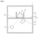
- FIG. 1 is a diagram schematically showing a configuration of an X-ray analyzer according to an embodiment of the present invention.
- the X-ray analyzer 1 includes a sample container 10, a case 20, an X-ray irradiation source 30, a detector 40, and a holder 50.
- the sample container 10 is a container for accommodating the sample S. As shown in FIG. 2, the sample container 10 has a container body 12 and a container film 14.
- the container body 12 has a shape that surrounds the sample S and opens downward.
- the container body 12 is made of, for example, polypropylene (PP).
- the container film 14 closes the opening 12a (see FIG. 2) of the container body 12 and supports the sample S.
- the container film 14 is made of polypropylene.
- the container film 14 is welded to the lower end of the container body 12.
- the container film 14 may be made of polyethylene terephthalate (PET) or the like.
- the case 20 houses the sample container 10 and the like.
- the case 20 is made of metal.
- the case 20 has an accommodating portion 22, a mounting portion 24, and a lid portion 26.
- the accommodating portion 22 is composed of the lower part of the case 20.
- the accommodating portion 22 accommodates the X-ray irradiation source 30 and the detector 40.
- the accommodating portion 22 has a shape that opens upward.
- the mounting portion 24 is connected to the upper end portion of the accommodating portion 22.
- the mounting portion 24 is a portion on which the sample container 10 is placed.
- the mounting portion 24 is provided with an opening 24h for passing X-rays emitted from the X-ray irradiation source 30.
- the opening 24h is set smaller than the outer shape of the container body 12. In other words, the outer shape of the container body 12 is larger than the opening 24h.
- the lid portion 26 surrounds the sample container 10. The lower end portion of the lid portion 26 is connected to the outer edge portion of the mounting portion 24.
- the X-ray irradiation source 30 is housed in the housing unit 22.
- the X-ray irradiation source 30 irradiates the sample S arranged in the sample container 10 with X-rays from below the mounting portion 24.
- Examples of the X-ray irradiation source 30 include an X-ray tube.
- the detector 40 is housed in the housing unit 22.
- the detector 40 detects fluorescent X-rays generated from the sample S that has received the X-rays emitted from the X-ray irradiation source 30 below the mounting unit 24. From the viewpoint of improving the analysis accuracy of the sample S, the detector 40 is preferably arranged in the vicinity of the opening 24h.
- the holder 50 is mounted on the mounting portion 24 and houses the sample container 10.
- the holder 50 is configured to be removable from the mounting portion 24. As shown in FIG. 2, the holder 50 has a surrounding cylinder 52 and a holder film 54.
- the surrounding cylinder 52 has an outer shape larger than that of the opening 24h.
- the surrounding cylinder 52 surrounds the sample container 10 and has a shape that opens downward.
- the surrounding cylinder 52 is formed in a cylindrical shape.
- the siege tube 52 is made of, for example, polypropylene.
- the height of the enclosing cylinder 52 is larger than the height of the sample container 10.
- the position of the surrounding cylinder 52 with respect to the opening 24h is determined by a positioning mechanism (not shown).
- the inner peripheral surface 52S of the surrounding cylinder 52 may be gradually reduced in diameter as it approaches the mounting portion 24. By doing so, the sample container 10 is guided to a predetermined position when the sample container 10 is arranged in the siege cylinder 52 from above the siege cylinder 52.
- the holder film 54 closes the opening 52a (see FIG. 2) of the surrounding cylinder 52. That is, two films (container film 14 and holder film 54) are laminated above the opening 24h.
- the holder film 54 is made of, for example, polypropylene.
- the holder film 54 is welded to the lower end of the surrounding cylinder 52.
- the thickness of the holder film 54 is about the same as the thickness of the container film 14.
- the thickness of the holder film 54 is preferably set to 0.5 times or more and 2 times or less the thickness of the container film 14.
- the holder film 54 may be formed of polyethylene terephthalate (PET) or the like.
- the holder film 54 is further arranged below the container film 14 that supports the sample S, even if the container film 14 is damaged or the like. , The drop of the sample S from the mounting portion 24 is suppressed. Therefore, dirt and the like of the detector 40 are suppressed.
- the holder 50 may further have a holding ring 56.
- the outer shape of the holder film 54 is set to be larger than the outer shape of the surrounding cylinder 52.
- the sandwiching ring 56 sandwiches the edge portion of the holder film 54 between the inner peripheral surface of the sandwiching ring 56 and the outer peripheral surface of the surrounding cylinder 52.
- the sample container 10 may further have a holding ring 16.
- the outer shape of the container film 14 is set to be larger than the outer shape of the container body 12.
- the sandwiching ring 16 sandwiches the edge portion of the container film 14 between the inner peripheral surface of the sandwiching ring 16 and the outer peripheral surface of the container body 12.
- the X-ray analyzer according to one embodiment is described above with respect to a sample container for accommodating a sample, a mounting portion on which the sample container can be placed, and the sample in the sample container.
- An X-ray irradiation source that irradiates X-rays from below the part, a detector that detects fluorescent X-rays generated from the sample below the above-mentioned place, and the sample that is placed on the above-mentioned place.
- a holder for accommodating a container is provided, and the above-mentioned placement portion is provided with an opening for passing X-rays emitted from the X-ray irradiation source, and the sample container surrounds the sample.
- the holder has a container body having a shape that opens downward and a container film that closes the opening of the container body and supports the sample, and the holder has a larger outer shape than the opening. It has a siege tube having a shape that surrounds the sample container and opens downward, and a holder film that closes the opening of the siege tube.
- the holder film may be welded to the lower end of the surrounding cylinder.
- the work of attaching the holder film to the surrounding cylinder is omitted.
- the holder further has a holding ring attached around the surrounding cylinder, and the holding ring is the inner peripheral surface of the holding ring.
- the edge portion of the holder film may be sandwiched between the outer peripheral surface of the surrounding cylinder.
- the outer shape of the container body is preferably larger than the opening.
- the sample can be analyzed by placing the sample container on the mounting portion.
- X-ray analyzer 10 sample container, 12 container body, 14 container film, 16 holding ring, 20 case, 22 accommodating part, 24 mounting part, 24h opening, 26 lid part, 30 X-ray irradiation source, 40 detection Container, 50 holder, 52 siege tube, 54 holder film, 56 holding ring, S sample.
Landscapes
- Physics & Mathematics (AREA)
- Health & Medical Sciences (AREA)
- Life Sciences & Earth Sciences (AREA)
- Chemical & Material Sciences (AREA)
- Analytical Chemistry (AREA)
- Biochemistry (AREA)
- General Health & Medical Sciences (AREA)
- General Physics & Mathematics (AREA)
- Immunology (AREA)
- Pathology (AREA)
- Analysing Materials By The Use Of Radiation (AREA)
Abstract
試料(S)を収容する試料容器(10)と、試料容器(10)を載置可能な載置部(24)と、試料(S)に対して載置部(24)の下方からX線を照射するX線照射源と、試料(S)から発生する蛍光X線を載置部の下方で検出する検出器と、載置部(24)に載置されており、試料容器(10)を収容するホルダー(50)と、を備え、載置部(24)には、開口部(24h)が設けられており、試料容器(10)は、試料(S)を包囲するとともに下方に開口する形状を有する容器本体(12)と、容器本体(12)の開口を閉塞するとともに試料(S)を支持する容器フィルム(14)と、を有し、ホルダー(50)は、開口部(24h)よりも大きな外形を有しかつ試料容器(10)を包囲するとともに、下方に開口する形状を有する包囲筒(52)と、包囲筒(52)の開口を閉塞するホルダーフィルム(54)と、を有する、X線分析装置。
Description
この発明は、X線分析装置に関する。
従来、X線を照射された試料から発生する蛍光X線を分析するX線分析装置が知られている。例えば、特開2018-63196号公報には、試料を載置可能な載置部を有する筐体部と、載置部に設けられた開口部を通じて試料にX線を照射するX線管球と、試料から発生する蛍光X線を検出する検出器と、を備えるX線分析装置が開示されている。X線管球及び検出器は、載置部の下方に配置されている。試料は、フィルムを介して載置部に載置される。
特開2018-63196号公報に記載されるようなX線分析装置では、フィルムの破損等によって試料の一部が開口部を通じて落下し、それが検出器に付着する場合がある。この場合、分析精度が低下する懸念がある。
本発明の目的は、試料の載置部からの落下を抑制可能なX線分析装置を提供することである。
本発明の第1態様は、試料を収容する試料容器と、前記試料容器を載置可能な載置部と、前記試料容器内の前記試料に対して前記載置部の下方からX線を照射するX線照射源と、前記試料から発生する蛍光X線を前記載置部の下方で検出する検出器と、前記載置部に載置されており、前記試料容器を収容するホルダーと、を備え、前記載置部には、前記X線照射源から照射されたX線を通過させるための開口部が設けられており、前記試料容器は、前記試料を包囲するとともに下方に開口する形状を有する容器本体と、前記容器本体の開口を閉塞するとともに前記試料を支持する容器フィルムと、を有し、前記ホルダーは、前記開口部よりも大きな外形を有しかつ前記試料容器を包囲するとともに、下方に開口する形状を有する包囲筒と、前記包囲筒の開口を閉塞するホルダーフィルムと、を有する、X線分析装置に関する。
このX線分析装置では、試料を支持する容器フィルムの下方にさらにホルダーフィルムが配置されているため、容器フィルムが破損等した場合においても、試料の載置部からの落下が抑制される。
この発明の実施形態について、図面を参照して説明する。なお、以下で参照する図面では、同一またはそれに相当する部材には、同じ番号が付されている。
図1は、本発明の一実施形態のX線分析装置の構成を概略的に示す図である。図1に示されるように、X線分析装置1は、試料容器10と、ケース20と、X線照射源30と、検出器40と、ホルダー50と、を備えている。
試料容器10は、試料Sを収容する容器である。図2に示されるように、試料容器10は、容器本体12と、容器フィルム14と、を有している。
容器本体12は、試料Sを包囲するとともに下方に開口する形状を有している。容器本体12は、例えば、ポリプロピレン(PP)からなる。
容器フィルム14は、容器本体12の開口12a(図2を参照)を閉塞するとともに、試料Sを支持している。本実施形態では、容器フィルム14は、ポリプロピレンからなる。容器フィルム14は、容器本体12の下端部に溶着されている。なお、容器フィルム14は、ポリエチレンテレフタレート(PET)等で形成されてもよい。
ケース20は、試料容器10等を収容している。ケース20は、金属からなる。図1に示されるように、ケース20は、収容部22と、載置部24と、蓋部26と、を有している。
収容部22は、ケース20の下部で構成されている。収容部22は、X線照射源30及び検出器40を収容している。収容部22は、上方に開口する形状を有している。
載置部24は、収容部22の上端部に接続されている。載置部24は、試料容器10が載置される部位である。載置部24には、X線照射源30から照射されるX線を通過させるための開口部24hが設けられている。開口部24hは、容器本体12の外形よりも小さく設定される。換言すれば、容器本体12の外形は、開口部24hよりも大きい。
蓋部26は、試料容器10を包囲している。蓋部26の下端部は、載置部24の外縁部に接続されている。
X線照射源30は、収容部22に収容されている。X線照射源30は、試料容器10内に配置された試料Sに対して載置部24の下方からX線を照射する。X線照射源30として、例えば、X線管球が挙げられる。
検出器40は、収容部22に収容されている。検出器40は、X線照射源30から照射されたX線を受けた試料Sから発生する蛍光X線を載置部24の下方で検出する。試料Sの分析精度を高める観点から、検出器40は、開口部24hの近傍に配置されることが好ましい。
ホルダー50は、載置部24に載置されており、試料容器10を収容している。ホルダー50は、載置部24から取外し可能に構成されている。図2に示されるように、ホルダー50は、包囲筒52と、ホルダーフィルム54と、を有している。
包囲筒52は、開口部24hよりも大きな外形を有している。包囲筒52は、試料容器10を包囲するとともに、下方に開口する形状を有している。本実施形態では、包囲筒52は、円筒状に形成されている。包囲筒52は、例えば、ポリプロピレンからなる。包囲筒52の高さは、試料容器10の高さよりも大きい。包囲筒52は、図示略の位置決め機構によって、開口部24hに対する位置が決定されている。包囲筒52の内周面52Sは、載置部24に近づくにしたがって次第に縮径していてもよい。このようにすれば、包囲筒52の上方から包囲筒52内に試料容器10を配置する際に試料容器10が所定の位置に案内される。
ホルダーフィルム54は、包囲筒52の開口52a(図2を参照)を閉塞している。つまり、開口部24hの上方には、2枚のフィルム(容器フィルム14及びホルダーフィルム54)が積層されている。ホルダーフィルム54は、例えば、ポリプロピレンからなる。ホルダーフィルム54は、包囲筒52の下端部に溶着されている。ホルダーフィルム54の厚みは、容器フィルム14の厚みと同程度である。例えば、ホルダーフィルム54の厚みは、容器フィルム14の厚みの0.5倍以上2倍以下に設定されることが好ましい。なお、ホルダーフィルム54は、ポリエチレンテレフタレート(PET)等で形成されてもよい。
以上に説明したように、本実施形態のX線分析装置1では、試料Sを支持する容器フィルム14の下方にさらにホルダーフィルム54が配置されているため、容器フィルム14が破損等した場合においても、試料Sの載置部24からの落下が抑制される。このため、検出器40の汚れ等が抑制される。
なお、今回開示された実施形態はすべての点で例示であって、制限的なものではないと考えられるべきである。本発明の範囲は、上記した実施形態の説明ではなく請求の範囲によって示され、さらに請求の範囲と均等の意味および範囲内でのすべての変更が含まれる。
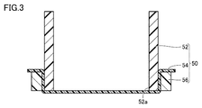
例えば、図3に示されるように、ホルダー50は、挟持リング56をさらに有していてもよい。この例では、ホルダーフィルム54の外形は、包囲筒52の外形よりも大きく設定されている。挟持リング56は、当該挟持リング56の内周面と包囲筒52の外周面との間にホルダーフィルム54の縁部を挟持している。
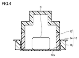
また、図4に示されるように、試料容器10は、挟持リング16をさらに有していてもよい。この例では、容器フィルム14の外形は、容器本体12の外形よりも大きく設定されている。挟持リング16は、当該挟持リング16の内周面と容器本体12の外周面との間に容器フィルム14の縁部を挟持している。
[態様]
上述した複数の例示的な実施形態は、以下の態様の具体例であることが当業者により理解される。
上述した複数の例示的な実施形態は、以下の態様の具体例であることが当業者により理解される。
(第1項)一態様に係る前記X線分析装置は、試料を収容する試料容器と、前記試料容器を載置可能な載置部と、前記試料容器内の前記試料に対して前記載置部の下方からX線を照射するX線照射源と、前記試料から発生する蛍光X線を前記載置部の下方で検出する検出器と、前記載置部に載置されており、前記試料容器を収容するホルダーと、を備え、前記載置部には、前記X線照射源から照射されたX線を通過させるための開口部が設けられており、前記試料容器は、前記試料を包囲するとともに下方に開口する形状を有する容器本体と、前記容器本体の開口を閉塞するとともに前記試料を支持する容器フィルムと、を有し、前記ホルダーは、前記開口部よりも大きな外形を有しかつ前記試料容器を包囲するとともに、下方に開口する形状を有する包囲筒と、前記包囲筒の開口を閉塞するホルダーフィルムと、を有する。
このX線分析装置では、試料を支持する容器フィルムの下方にさらにホルダーフィルムが配置されているため、容器フィルムが破損等した場合においても、試料の載置部からの落下が抑制される。
(第2項)第1項に記載のX線分析装置において、前記ホルダーフィルムは、前記包囲筒の下端部に溶着されていてもよい。
この態様では、ホルダーフィルムの包囲筒への取付作業が省略される。
(第3項)第1項に記載のX線分析装置において、前記ホルダーは、前記包囲筒の周囲に取り付けられた挟持リングをさらに有し、前記挟持リングは、当該挟持リングの内周面と前記包囲筒の外周面との間に前記ホルダーフィルムの縁部を挟持していてもよい。
(第3項)第1項に記載のX線分析装置において、前記ホルダーは、前記包囲筒の周囲に取り付けられた挟持リングをさらに有し、前記挟持リングは、当該挟持リングの内周面と前記包囲筒の外周面との間に前記ホルダーフィルムの縁部を挟持していてもよい。
この態様では、包囲筒に対する溶着が困難な材料(例えば、包囲筒を構成する材料とは異なる材料)からなるホルダーフィルムを包囲筒に取り付けることが可能となる。
(第4項)第1項から第3項のいずれかに記載のX線分析装置において、前記ホルダーは、前記載置部から取外し可能に構成されていることが好ましい。
このようにすれば、X線照射源や検出器を傷付けることなく、ホルダーフィルムの洗浄やホルダー自体の交換等が可能となる。
(第5項)第1項から第4項のいずれかに記載のX線分析装置において、前記容器本体の外形は、前記開口部よりも大きいことが好ましい。
このようにすれば、包囲筒にホルダーフィルムが取り付けられていない場合においても、試料容器を載置部に載置することによって試料の分析が可能となる。
1 X線分析装置、10 試料容器、12 容器本体、14 容器フィルム、16 挟持リング、20 ケース、22 収容部、24 載置部、24h 開口部、26 蓋部、30 X線照射源、40 検出器、50 ホルダー、52 包囲筒、54 ホルダーフィルム、56 挟持リング、S 試料。
Claims (5)
- 試料を収容する試料容器と、
前記試料容器を載置可能な載置部と、
前記試料容器内の前記試料に対して前記載置部の下方からX線を照射するX線照射源と、
前記試料から発生する蛍光X線を前記載置部の下方で検出する検出器と、
前記載置部に載置されており、前記試料容器を収容するホルダーと、を備え、
前記載置部には、前記X線照射源から照射されたX線を通過させるための開口部が設けられており、
前記試料容器は、
前記試料を包囲するとともに下方に開口する形状を有する容器本体と、
前記容器本体の開口を閉塞するとともに前記試料を支持する容器フィルムと、を有し、
前記ホルダーは、
前記開口部よりも大きな外形を有しかつ前記試料容器を包囲するとともに、下方に開口する形状を有する包囲筒と、
前記包囲筒の開口を閉塞するホルダーフィルムと、を有する、X線分析装置。 - 前記ホルダーフィルムは、前記包囲筒の下端部に溶着されている、請求項1に記載のX線分析装置。
- 前記ホルダーは、前記包囲筒の周囲に取り付けられた挟持リングをさらに有し、
前記挟持リングは、当該挟持リングの内周面と前記包囲筒の外周面との間に前記ホルダーフィルムの縁部を挟持している、請求項1に記載のX線分析装置。 - 前記ホルダーは、前記載置部から取外し可能に構成されている、請求項1から3のいずれかに記載のX線分析装置。
- 前記容器本体の外形は、前記開口部よりも大きい、請求項1から4のいずれかに記載のX線分析装置。
Priority Applications (6)
| Application Number | Priority Date | Filing Date | Title |
|---|---|---|---|
| CN202080102470.2A CN115715365A (zh) | 2020-07-01 | 2020-07-01 | X射线分析装置 |
| JP2022532907A JPWO2022003850A1 (ja) | 2020-07-01 | 2020-07-01 | |
| US18/013,198 US20230236142A1 (en) | 2020-07-01 | 2020-07-01 | X-ray analyzer |
| PCT/JP2020/025763 WO2022003850A1 (ja) | 2020-07-01 | 2020-07-01 | X線分析装置 |
| EP20943512.2A EP4177600A4 (en) | 2020-07-01 | 2020-07-01 | X-RAY ANALYZER |
| TW110117615A TWI787821B (zh) | 2020-07-01 | 2021-05-17 | X射線分析裝置 |
Applications Claiming Priority (1)
| Application Number | Priority Date | Filing Date | Title |
|---|---|---|---|
| PCT/JP2020/025763 WO2022003850A1 (ja) | 2020-07-01 | 2020-07-01 | X線分析装置 |
Publications (1)
| Publication Number | Publication Date |
|---|---|
| WO2022003850A1 true WO2022003850A1 (ja) | 2022-01-06 |
Family
ID=79315789
Family Applications (1)
| Application Number | Title | Priority Date | Filing Date |
|---|---|---|---|
| PCT/JP2020/025763 WO2022003850A1 (ja) | 2020-07-01 | 2020-07-01 | X線分析装置 |
Country Status (6)
| Country | Link |
|---|---|
| US (1) | US20230236142A1 (ja) |
| EP (1) | EP4177600A4 (ja) |
| JP (1) | JPWO2022003850A1 (ja) |
| CN (1) | CN115715365A (ja) |
| TW (1) | TWI787821B (ja) |
| WO (1) | WO2022003850A1 (ja) |
Citations (8)
| Publication number | Priority date | Publication date | Assignee | Title |
|---|---|---|---|---|
| JPH04331349A (ja) * | 1991-05-03 | 1992-11-19 | Horiba Ltd | 蛍光x線分析装置 |
| JPH04355355A (ja) * | 1991-05-31 | 1992-12-09 | Rigaku Denki Kogyo Kk | 蛍光x線分析装置における窓材の汚染検出方法 |
| US5703927A (en) * | 1993-04-15 | 1997-12-30 | Angelo M. Torrisi | Safety ring for double open-ended sample holder cell for spectroscopic analysis |
| WO2004088296A1 (ja) * | 2003-03-28 | 2004-10-14 | Rigaku Industrial Corporation | 蛍光x線分析装置 |
| JP2006317153A (ja) * | 2005-05-10 | 2006-11-24 | Rigaku Industrial Co | 蛍光x線分析用試料保持具ならびにそれを用いる蛍光x線分析方法および装置 |
| JP2011013027A (ja) * | 2009-06-30 | 2011-01-20 | Horiba Ltd | 蛍光x線分析装置 |
| JP2011089794A (ja) * | 2009-10-20 | 2011-05-06 | Rigaku Corp | 蛍光x線分析用試料保持具ならびにそれを用いる蛍光x線分析方法および装置 |
| JP2018063196A (ja) | 2016-10-14 | 2018-04-19 | 株式会社島津製作所 | X線分析装置 |
Family Cites Families (3)
| Publication number | Priority date | Publication date | Assignee | Title |
|---|---|---|---|---|
| JP5907375B2 (ja) * | 2011-12-28 | 2016-04-26 | 株式会社テクノエックス | 蛍光x線分析装置及び蛍光x線分析方法 |
| DE102014115383A1 (de) * | 2014-08-01 | 2016-02-04 | Helmut Fischer GmbH Institut für Elektronik und Messtechnik | Handgerät sowie mobile Einrichtung zur Röntgenfluoreszenzanalyse |
| CN108956672B (zh) * | 2018-05-15 | 2021-12-17 | 江苏天瑞仪器股份有限公司 | 使用食品快检仪专用样品杯进行重金属检测的检测方法 |
-
2020
- 2020-07-01 CN CN202080102470.2A patent/CN115715365A/zh active Pending
- 2020-07-01 EP EP20943512.2A patent/EP4177600A4/en active Pending
- 2020-07-01 US US18/013,198 patent/US20230236142A1/en active Pending
- 2020-07-01 JP JP2022532907A patent/JPWO2022003850A1/ja active Pending
- 2020-07-01 WO PCT/JP2020/025763 patent/WO2022003850A1/ja unknown
-
2021
- 2021-05-17 TW TW110117615A patent/TWI787821B/zh active
Patent Citations (8)
| Publication number | Priority date | Publication date | Assignee | Title |
|---|---|---|---|---|
| JPH04331349A (ja) * | 1991-05-03 | 1992-11-19 | Horiba Ltd | 蛍光x線分析装置 |
| JPH04355355A (ja) * | 1991-05-31 | 1992-12-09 | Rigaku Denki Kogyo Kk | 蛍光x線分析装置における窓材の汚染検出方法 |
| US5703927A (en) * | 1993-04-15 | 1997-12-30 | Angelo M. Torrisi | Safety ring for double open-ended sample holder cell for spectroscopic analysis |
| WO2004088296A1 (ja) * | 2003-03-28 | 2004-10-14 | Rigaku Industrial Corporation | 蛍光x線分析装置 |
| JP2006317153A (ja) * | 2005-05-10 | 2006-11-24 | Rigaku Industrial Co | 蛍光x線分析用試料保持具ならびにそれを用いる蛍光x線分析方法および装置 |
| JP2011013027A (ja) * | 2009-06-30 | 2011-01-20 | Horiba Ltd | 蛍光x線分析装置 |
| JP2011089794A (ja) * | 2009-10-20 | 2011-05-06 | Rigaku Corp | 蛍光x線分析用試料保持具ならびにそれを用いる蛍光x線分析方法および装置 |
| JP2018063196A (ja) | 2016-10-14 | 2018-04-19 | 株式会社島津製作所 | X線分析装置 |
Non-Patent Citations (1)
| Title |
|---|
| See also references of EP4177600A4 |
Also Published As
| Publication number | Publication date |
|---|---|
| TW202202834A (zh) | 2022-01-16 |
| TWI787821B (zh) | 2022-12-21 |
| US20230236142A1 (en) | 2023-07-27 |
| JPWO2022003850A1 (ja) | 2022-01-06 |
| EP4177600A4 (en) | 2024-03-06 |
| CN115715365A (zh) | 2023-02-24 |
| EP4177600A1 (en) | 2023-05-10 |
Similar Documents
| Publication | Publication Date | Title |
|---|---|---|
| JP4854005B2 (ja) | 蛍光x線分析装置 | |
| JPH04331349A (ja) | 蛍光x線分析装置 | |
| EP3029455A1 (en) | X-ray fluorescence analyzer | |
| US20130279654A1 (en) | Apparatus for protecting a radiation window | |
| WO2022003850A1 (ja) | X線分析装置 | |
| CN107957430B (zh) | X射线分析装置 | |
| JP2011203102A (ja) | 試料ホルダ及び試料分析方法 | |
| JP2943063B2 (ja) | 蛍光x線分析装置 | |
| JPH09509502A (ja) | ポリエチレンナフタレートx線窓 | |
| US6700951B2 (en) | X-ray fluorescence spectrometer | |
| JP2016105090A (ja) | 比濁分析濁度計 | |
| JP6227068B1 (ja) | 試料容器保持部材、光計測装置及び試料容器配置方法 | |
| JP5072704B2 (ja) | 放射線検査装置 | |
| JP6863069B2 (ja) | X線蛍光分析装置及びそれに用いられるサンプル容器 | |
| JP2011013029A (ja) | 蛍光x線分析装置 | |
| JP2014130169A (ja) | 蛍光x線分析装置 | |
| JPH11160492A (ja) | 放射性物質貯蔵容器 | |
| JP5524521B2 (ja) | 蛍光x線分析装置 | |
| JP4771985B2 (ja) | 放射線検査装置 | |
| JP2022181989A (ja) | X線分析装置 | |
| KR102559077B1 (ko) | 실시간 선량 감시가 가능한 방사성 폐기물 운반용기 | |
| JPWO2022003850A5 (ja) | ||
| JP3089817B2 (ja) | 陽電子消滅法による材料劣化検出装置 | |
| JP4264178B2 (ja) | 上面照射型x線分析用液体試料セルとこれを用いた上面照射型x線分析方法および装置 | |
| JP3210530U (ja) | 蛍光x線分析用一体化試料及び試料保持具 |
Legal Events
| Date | Code | Title | Description |
|---|---|---|---|
| 121 | Ep: the epo has been informed by wipo that ep was designated in this application |
Ref document number: 20943512 Country of ref document: EP Kind code of ref document: A1 |
|
| ENP | Entry into the national phase |
Ref document number: 2022532907 Country of ref document: JP Kind code of ref document: A |
|
| NENP | Non-entry into the national phase |
Ref country code: DE |
|
| ENP | Entry into the national phase |
Ref document number: 2020943512 Country of ref document: EP Effective date: 20230201 |