WO2021256502A1 - ガタツキが抑制されるハンドルスイッチ装置 - Google Patents
ガタツキが抑制されるハンドルスイッチ装置 Download PDFInfo
- Publication number
- WO2021256502A1 WO2021256502A1 PCT/JP2021/022844 JP2021022844W WO2021256502A1 WO 2021256502 A1 WO2021256502 A1 WO 2021256502A1 JP 2021022844 W JP2021022844 W JP 2021022844W WO 2021256502 A1 WO2021256502 A1 WO 2021256502A1
- Authority
- WO
- WIPO (PCT)
- Prior art keywords
- positioning protrusion
- handlebar
- switch device
- fitting hole
- handle switch
- Prior art date
- Legal status (The legal status is an assumption and is not a legal conclusion. Google has not performed a legal analysis and makes no representation as to the accuracy of the status listed.)
- Ceased
Links
Images



Classifications
-
- B—PERFORMING OPERATIONS; TRANSPORTING
- B62—LAND VEHICLES FOR TRAVELLING OTHERWISE THAN ON RAILS
- B62J—CYCLE SADDLES OR SEATS; AUXILIARY DEVICES OR ACCESSORIES SPECIALLY ADAPTED TO CYCLES AND NOT OTHERWISE PROVIDED FOR, e.g. ARTICLE CARRIERS OR CYCLE PROTECTORS
- B62J6/00—Arrangement of optical signalling or lighting devices on cycles; Mounting or supporting thereof; Circuits therefor
- B62J6/16—Arrangement of switches
-
- B—PERFORMING OPERATIONS; TRANSPORTING
- B62—LAND VEHICLES FOR TRAVELLING OTHERWISE THAN ON RAILS
- B62K—CYCLES; CYCLE FRAMES; CYCLE STEERING DEVICES; RIDER-OPERATED TERMINAL CONTROLS SPECIALLY ADAPTED FOR CYCLES; CYCLE AXLE SUSPENSIONS; CYCLE SIDECARS, FORECARS, OR THE LIKE
- B62K23/00—Rider-operated controls specially adapted for cycles, i.e. means for initiating control operations, e.g. levers, grips
- B62K23/02—Rider-operated controls specially adapted for cycles, i.e. means for initiating control operations, e.g. levers, grips hand actuated
Definitions
- the present invention relates to a steering wheel switch device attached to a steering wheel bar of a vehicle.
- a handle switch device that can be attached to the handlebar of a vehicle represented by a two-wheeled vehicle.
- a positioning protrusion is provided in the switch housing of the handle switch device, and the protrusion is engaged with a fitting hole formed in the handle bar to position the handle switch device with respect to the handle bar.
- the tip of the positioning protrusion is tapered so that the positioning protrusion can be fitted into the fitting hole without a gap.
- the handle switch device may rattle depending on the engagement state between the positioning protrusion and the fitting hole.
- the present invention more reliably suppresses rattling that occurs in the handle switch device.
- the handle switch device of the present invention is integrally formed with the switch housing attached to the handlebar of the vehicle and the switch housing, or is fixed to the switch housing and formed on the handlebar. It has a positioning protrusion that positions the switch housing with respect to the handlebar by engaging with the fitting hole, and the positioning protrusion is engaged with the fitting hole of the handlebar.
- the maximum width of the handlebar in the axial direction is the direction orthogonal to the protruding direction of the positioning protrusion and the axial direction with respect to the cross-sectional shape of the positioning protrusion. It is characterized in that it is configured to be smaller than the maximum width in.
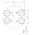
- FIG. 1 It is an exploded perspective view of the handle switch device. It is a figure which shows the plate. It is sectional drawing which follows the AA line of FIG. It is sectional drawing which follows the line BB of FIG. It is a perspective view which shows the positioning protrusion of the modification. It is sectional drawing of the positioning protrusion of the modification. It is sectional drawing of the positioning protrusion of the modification. It is sectional drawing of the positioning protrusion of the modification.
- FIG. 1 is an exploded perspective view of the handle switch device 100 according to the embodiment of the present invention.
- the steering wheel switch device 100 is attached to the handlebar 10 of a vehicle typified by a two-wheeled vehicle.
- the handlebar to which the handle switch device 100 is attached may be cylindrical as long as it is not limited to a two-wheeled vehicle, and may be a handlebar of a three-wheeled vehicle or a four-wheeled vehicle.
- the handle switch device 100 has a front housing 11 and a rear housing 12 as switch housings that cover the right end of the handlebar 10.
- the front housing 11 and the rear housing 12 are arranged substantially front and rear in the traveling direction of the vehicle.
- Various switches are attached to the front housing 11 arranged on the driver side.
- the switch 13 is an engine stop switch.
- the switch 14 is a hazard switch.
- the switch 15 is a start switch.
- the front housing 11 and the rear housing 12 are fastened to each other by two screws 41 and 42, and are fixed to the handlebar 10 so as to sandwich the handlebar 10 from the front-rear direction.
- the front housing 11 and the rear housing 12 are each integrally formed of resin.
- the handlebar 10 is made of metal.
- a fitting hole 10a is formed in the handlebar 10.
- a metal plate 20 is fixed to the inside of the rear housing 12 by screws 17 and 18. The detailed configuration of the plate 20 will be described later, but the plate 20 is formed with a positioning protrusion 30.
- the positioning protrusion 30 engages with the fitting hole 10a of the handlebar 10.
- the switch housing is positioned with respect to the handlebar 10 with respect to the axial direction of the handlebar 10 (center axis X1 direction) and the rotation direction (circumferential direction) of the handlebar 10 about the central axis X1.
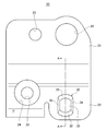
- FIG. 2 is a diagram showing a plate 20.
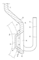
- FIG. 3 is a cross-sectional view taken along the line AA of FIG.
- the plate 20 has a flat first base portion 21 and a second base portion 22, respectively.
- the first base portion 21 and the second base portion 22 are connected by a slope portion.
- An extending portion 27 extends from the second base portion 22 via a bent portion (FIG. 3).
- the hole 26 in the first base portion 21 is a hole through which the screw 41 for fastening the front housing 11 and the rear housing 12 passes.
- the screw 17 is screwed into the rear housing 12 through the hole 23 of the first base portion 21, and the screw 18 is screwed into the rear housing 12 through the hole 25 of the extension portion 27.
- the hole 24 of the second base portion 22 is an escape hole for screwing the screw 18.
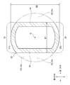
- FIG. 4 is a cross-sectional view taken along the line BB of FIG.
- the positioning protrusion 30 is integrally formed with the plate 20 which is a metal member.
- the positioning protrusion 30 is formed so as to project from the second base portion 22 toward the central axis X1 of the handlebar 10.
- the positioning protrusion 30 is a recess recessed toward the side where the central axis X1 is located.
- the tip of the positioning protrusion 30 is a substantially flat top surface portion 35.
- the positioning protrusion 30 has a first meat portion 31, a second meat portion 32, a third meat portion 33, and a fourth meat portion 34.
- the tips of these meat portions are connected to each other by the top surface portion 35 (FIGS. 2 and 3).
- the outer shell of the positioning protrusion 30 is formed in a tapered shape. That is, the outer surface of the meat portions 31 to 34 has a tapered shape.
- the outer surfaces of the meat portions 33 and 34 do not have to have a tapered shape, and may be, for example, parallel to the protruding direction of the positioning protrusion 30.
- the positioning protrusion 30 is designed so as to be able to engage with the fitting hole 10a in the engagement region R0 (FIG. 3) in the protrusion direction. That is, in a state where the positioning protrusion 30 is engaged with the fitting hole 10, the positioning protrusion 30 and the fitting hole 10 overlap each other in the engagement region R0.
- the direction orthogonal to the protruding direction of the positioning protrusion 30 and parallel to the central axis X1 is the first direction (axial direction), and the direction orthogonal to the protruding direction and the axial direction is the second direction.
- a virtual circle C0 circumscribing the positioning projection 30 is a virtual circle included in a virtual plane perpendicular to the protruding direction of the positioning protrusion 30.
- the end position of the fitting hole 10a on the side far from the central axis X1 is shown as a circle corresponding to one of the virtual circles C0.
- the positioning protrusion 30 has a region where the diameter of the virtual circle C0 becomes smaller toward the tip in the protrusion direction. This region includes the engagement region R0. At least in the engagement region R0, the cross-sectional shape of the positioning protrusion 30 is annular. The center of gravity G indicates the position of the center of gravity of this cross-sectional shape.
- the tapered positioning protrusion tends to strongly abut on both ends of the fitting hole in the axial direction of the handlebar.
- the positioning protrusions are mainly engaged at the positions of both ends of the fitting hole in the axial direction of the handlebar, there is a problem that the rattling in the axial direction is small but the rattling in the rotational direction is large. Since rattling in the rotation direction is easily recognized by the user, it is desirable to suppress it as much as possible. Therefore, as described below, in the present embodiment, attention is paid to the engagement relationship between the positioning protrusion 30 and the fitting hole 10a, and rattling is suppressed.
- the first meat portion 31 and the second meat portion 32 are meat portions having arc portions 31a and 32a along the virtual circle C0, respectively.
- the first meat portion 31 and the second meat portion 32 correspond to a pair of arcuate wall portions located at both ends in the second direction.
- One ends of the first meat portion 31 and the second meat portion 32 in the first direction are connected to each other by the third meat portion 33, and the other ends of the first meat portion 31 and the second meat portion 32 in the first direction are connected to each other. It is connected by the fourth meat portion 34.
- the second direction is the longitudinal direction. That is, at least in the engagement region R0, the maximum width B1 in the first direction is shorter (smaller) than the maximum width B2 in the second direction with respect to the cross-sectional shape of the positioning protrusion 30.
- the third meat portion 33 and the fourth meat portion 34 do not engage with the fitting hole 10a at the intermediate position in the second direction (longitudinal direction), and the first meat portion 31 and the second meat portion 32 do not engage with each other. Engages with the fitting hole 10a. Therefore, the positioning protrusion 30 is firmly positioned in the second direction with respect to the fitting hole 10a. As a result, rattling of the switch housing with respect to the handlebar 10 in the rotation direction about the central axis X1 is suppressed.
- the positioning protrusion 30 is formed with relief portions 33x and 34x for securing gaps S1 and S2 between the positioning protrusion 30 and the fitting hole 10a in the first direction in a state of being engaged with the fitting hole 10a. ing. That is, by forming the relief portions 33x and 34x with respect to the conical shape having a flat tip, both ends of the positioning projection 30 in the first direction come into contact with the fitting hole 10a at the intermediate position in the second direction. It disappears. As a result, the positioning protrusion 30 engages with the fitting hole 10a at the arc portion 31a of the first meat portion 31 and the arc portion 32a of the second meat portion 32.
- the maximum width B1 in the first direction is shorter than the maximum width B2 in the second direction with respect to the cross-sectional shape of the positioning protrusion 30.
- the positioning protrusion 30 has a hollow recess, it contributes to material saving and weight reduction.
- the positioning protrusion 30 has such a shape, the tip portions of the meat portions 31 and 32 having the arc portions 31a and 32a that engage with the fitting hole 10a are connected to each other by the top surface portion 35, so that the positioning protrusion 30 is connected to each other. It is possible to secure a high strength of 30. Further, high strength can be ensured by the fact that the cross-sectional shape of the positioning protrusion 30 is annular in the engaging region R0. From the viewpoint of further improving the strength, the positioning protrusion 30 may have a solid structure that does not have a concave shape.
- the positioning protrusion 30 is integrally formed with the plate 20 which is a metal member fixed to the switch housing, the number of parts can be suppressed and the durability can be improved.
- the positioning protrusion 30 may be integrally formed with the switch housing or fixed to the switch housing. That is, the positioning protrusion 30 is not essential to be formed on the plate 20, and may be integrally configured with the switch housing.
- the positioning protrusion 30 is a metal member and may be configured to be integrated with the rear housing 12.
- a pedestal 36 is integrally formed with the rear housing 12.
- the pedestal 36 of the rear housing 12 is provided with a positioning protrusion 30 which is a metal pin by insert molding or the like.
- the metal positioning protrusion 30 is integrally formed with the resin rear housing 12.
- the metal positioning protrusion 30 may be fixed to the rear housing 12 by press fitting.
- the positioning protrusion 30 may be integrally formed with the switch housing.
- the pedestal 36 and the positioning protrusion 30 may be integrally formed with the resin rear housing 12 by injection molding.
- the pedestal 36 may be in the form of a boss. The pedestal 36 is not essential.
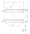
- FIGS. 6 to 8. are cross-sectional views of the positioning protrusion 30 of the modified example, and correspond to FIG. 4.
- the positioning protrusion 30 shown in FIG. 6 has a configuration in which the third meat portion 33 and the fourth meat portion 34 are abolished as compared with the example shown in FIG.
- the tips of the meat portions 31 and 32 are connected to each other by the top surface portion 35.
- the engagement relationship between the meat portions 31 and 32 and the virtual circle C0 and the fitting hole 10a is the same as the example shown in FIG.
- the positioning protrusion 30 shown in FIG. 7 has a configuration in which the first meat portion 31 and the second meat portion 32 are abolished as compared with the example shown in FIG.
- both ends of the third meat portion 33 in the second direction have arc portions 33a1 and 33a2 along the virtual circle C0.
- both ends of the fourth meat portion 34 in the second direction have arc portions 34a1 and 34a2 along the virtual circle C0.
- the tips of the meat portions 33 and 34 are connected to each other by the top surface portion 35.
- the arc portions 33a1, 33a2, 34a1, 34a2 engage with the fitting hole 10a.
- the positioning protrusion 30 shown in FIG. 8 has pillar portions 37A, 37B, 38A, 38B whose diameter becomes smaller toward the tip in the protrusion direction.
- the tip portions of the pillar portions 37A, 37B, 38A, and 38B are connected to each other by the top surface portion 35.
- the pillar portions 37A, 37B, 38A, 38B engage with the fitting hole 10a.
- the tip portion of the positioning protrusion 30 does not need to be connected by a flat wall such as the top surface portion 35.
- the tip of the positioning protrusion 30 may be sharp, and the meat portions or the pillar portions may be connected to each other at the tip position of the positioning protrusion 30.
- positioning protrusion 30 is provided in the rear housing 12 in the above example, it may be provided in the front housing 11.
- the handle switch device 100 is attached to the right end of the handlebar 10, but the present invention can also be applied to the handle switch device attached to the left end of the handlebar 10.
- the curvature of the fitting hole 10a (or the virtual circle C0) matches the curvature of the arc portions 31a and 32a.
- the curvatures of the arc portions 31a and 32a at the positions where they engage with the fitting holes 10a are set smaller than the fitting holes 10a (the radius of curvature is increased), and each of the arc portions 31a and 32a is set in the fitting holes 10a.
- the contact may be made at a plurality of places. By doing so, the fixed state of the handlebar 10 and the handle switch device 100 becomes more reliable.
Landscapes
- Engineering & Computer Science (AREA)
- Mechanical Engineering (AREA)
- Switch Cases, Indication, And Locking (AREA)
Abstract
Description
10a 嵌合穴
11 フロントハウジング
12 リアハウジング
20 プレート
30 位置決め突起
31~34 肉部
33a1、33a2、34a1、34a2 円弧部
35 天面部
37A、37B、38A、38B 柱部
100 ハンドルスイッチ装置
C0 仮想円
R0 領域
B1、B2 最大幅
S1、S2 間隙
33x、34x 逃げ部
Claims (11)
- 車両のハンドルバーに取り付けられるスイッチハウジングと、
前記スイッチハウジングに一体に形成されるかまたは前記スイッチハウジングに固定され、前記ハンドルバーに形成された嵌合穴と係合することで前記スイッチハウジングを前記ハンドルバーに対して位置決めする位置決め突起と、を有し、
前記位置決め突起が、前記ハンドルバーの前記嵌合穴と係合した状態において、前記位置決め突起と前記嵌合穴が重なる領域においては、前記位置決め突起の断面形状に関し、前記ハンドルバーの軸線方向における最大幅の方が、前記位置決め突起の突出方向と前記軸線方向とに直交する方向における最大幅よりも小さくなるように構成されていることを特徴とするハンドルスイッチ装置。 - 前記位置決め突起は前記位置決め突起に外接する仮想円の直径が、前記位置決め突起の突出方向先端にいくほど小さくなる領域を有することを特徴とする請求項1に記載のハンドルスイッチ装置。
- 前記位置決め突起は、前記仮想円に沿った円弧部を有する肉部を含むことを特徴とする請求項1または2に記載のハンドルスイッチ装置。
- 前記肉部は、前記突出方向と前記軸線方向とに直交する方向における両端部に位置する一対の円弧状壁部であることを特徴とする請求項3に記載のハンドルスイッチ装置。
- 前記一対の円弧状壁部の先端部同士が接続されていることを特徴とする請求項4に記載のハンドルスイッチ装置。
- 少なくとも前記領域においては、前記位置決め突起の断面形状は環状であることを特徴とする請求項1に記載のハンドルスイッチ装置。
- 前記位置決め突起は、前記スイッチハウジングに固定された部材に一体に形成されることを特徴とする請求項1に記載のハンドルスイッチ装置。
- 前記固定された部材は金属である事を特徴とする請求項7に記載のハンドルスイッチ装置。
- 前記位置決め突起は、前記スイッチハウジングに一体に形成されることを特徴とする請求項1に記載のハンドルスイッチ装置。
- 前記位置決め突起は、前記スイッチハウジングと一体となるように構成された金属部材であることを特徴とする請求項1に記載のハンドルスイッチ装置。
- 車両のハンドルバーに取り付けられるスイッチハウジングと、
前記スイッチハウジングに一体に形成されるかまたは前記スイッチハウジングに固定され、前記ハンドルバーに形成された嵌合穴と係合することで前記スイッチハウジングを前記ハンドルバーに対して位置決めする位置決め突起と、を有し、
前記位置決め突起は、先細のテーパ形状であり、
前記位置決め突起が前記ハンドルバーの前記嵌合穴と係合した状態において、前記ハンドルバーの軸線方向において前記位置決め突起と前記嵌合穴との間に間隙が確保されることを特徴とするハンドルスイッチ装置。
Priority Applications (2)
| Application Number | Priority Date | Filing Date | Title |
|---|---|---|---|
| JP2022531870A JP7502438B2 (ja) | 2020-06-19 | 2021-06-16 | ガタツキが抑制されるハンドルスイッチ装置 |
| CN202180042222.8A CN115884919B (zh) | 2020-06-19 | 2021-06-16 | 抑制晃动的把手开关装置 |
Applications Claiming Priority (2)
| Application Number | Priority Date | Filing Date | Title |
|---|---|---|---|
| JP2020-105964 | 2020-06-19 | ||
| JP2020105964 | 2020-06-19 |
Publications (1)
| Publication Number | Publication Date |
|---|---|
| WO2021256502A1 true WO2021256502A1 (ja) | 2021-12-23 |
Family
ID=79267971
Family Applications (1)
| Application Number | Title | Priority Date | Filing Date |
|---|---|---|---|
| PCT/JP2021/022844 Ceased WO2021256502A1 (ja) | 2020-06-19 | 2021-06-16 | ガタツキが抑制されるハンドルスイッチ装置 |
Country Status (3)
| Country | Link |
|---|---|
| JP (1) | JP7502438B2 (ja) |
| CN (1) | CN115884919B (ja) |
| WO (1) | WO2021256502A1 (ja) |
Citations (5)
| Publication number | Priority date | Publication date | Assignee | Title |
|---|---|---|---|---|
| JPS59188783U (ja) * | 1983-06-03 | 1984-12-14 | 株式会社東海理化電機製作所 | 二輪車用ハンドルスイツチ固定装置 |
| JPH06321160A (ja) * | 1993-05-12 | 1994-11-22 | Suzuki Motor Corp | 自動二輪車のハンドルスイッチ取付構造 |
| JP2006335204A (ja) * | 2005-06-01 | 2006-12-14 | Asahi Denso Co Ltd | ハンドルスイッチ装置 |
| JP2007324051A (ja) * | 2006-06-02 | 2007-12-13 | Toyo Denso Co Ltd | 車両用ターンシグナルスイッチ |
| JP2009013833A (ja) * | 2007-07-03 | 2009-01-22 | Honda Motor Co Ltd | 車両のスロットル装置 |
Family Cites Families (3)
| Publication number | Priority date | Publication date | Assignee | Title |
|---|---|---|---|---|
| JPH11312429A (ja) * | 1998-04-28 | 1999-11-09 | Suzuki Motor Corp | 二輪車のスイッチケース装置 |
| JP4416160B2 (ja) * | 2004-03-25 | 2010-02-17 | 朝日電装株式会社 | 自動二輪車用ハンドルスイッチの固定構造 |
| JP2011046278A (ja) * | 2009-08-27 | 2011-03-10 | Asahi Denso Co Ltd | ハンドルバー用スイッチ装置 |
-
2021
- 2021-06-16 WO PCT/JP2021/022844 patent/WO2021256502A1/ja not_active Ceased
- 2021-06-16 CN CN202180042222.8A patent/CN115884919B/zh active Active
- 2021-06-16 JP JP2022531870A patent/JP7502438B2/ja active Active
Patent Citations (5)
| Publication number | Priority date | Publication date | Assignee | Title |
|---|---|---|---|---|
| JPS59188783U (ja) * | 1983-06-03 | 1984-12-14 | 株式会社東海理化電機製作所 | 二輪車用ハンドルスイツチ固定装置 |
| JPH06321160A (ja) * | 1993-05-12 | 1994-11-22 | Suzuki Motor Corp | 自動二輪車のハンドルスイッチ取付構造 |
| JP2006335204A (ja) * | 2005-06-01 | 2006-12-14 | Asahi Denso Co Ltd | ハンドルスイッチ装置 |
| JP2007324051A (ja) * | 2006-06-02 | 2007-12-13 | Toyo Denso Co Ltd | 車両用ターンシグナルスイッチ |
| JP2009013833A (ja) * | 2007-07-03 | 2009-01-22 | Honda Motor Co Ltd | 車両のスロットル装置 |
Also Published As
| Publication number | Publication date |
|---|---|
| CN115884919A (zh) | 2023-03-31 |
| CN115884919B (zh) | 2025-05-30 |
| JP7502438B2 (ja) | 2024-06-18 |
| JPWO2021256502A1 (ja) | 2021-12-23 |
Similar Documents
| Publication | Publication Date | Title |
|---|---|---|
| TWI731416B (zh) | 用於兩輪及三輪車輛車把之止動件及該止動件之製造方法 | |
| JP5273089B2 (ja) | ステアリング装置 | |
| JP2012126222A (ja) | 車両用アウトサイドミラー装置 | |
| JP3811266B2 (ja) | 自動二輪車におけるフロントフェンダー装置 | |
| JP6502297B2 (ja) | 鞍乗り型車両 | |
| JP2016064721A5 (ja) | ||
| WO2021256502A1 (ja) | ガタツキが抑制されるハンドルスイッチ装置 | |
| JP4390135B2 (ja) | ステアリング装置 | |
| CN104024082A (zh) | 转向锁定装置 | |
| JP6882120B2 (ja) | 電動ステアリングコラム装置 | |
| JP7528842B2 (ja) | ステアリングハンドル | |
| JP2021000944A (ja) | ハンドルスイッチ装置 | |
| JP6896566B2 (ja) | 電動ステアリングコラム装置 | |
| JPWO2018181082A1 (ja) | ステアリング装置 | |
| JP2019217859A (ja) | 鞍乗型車両の方向指示器取付構造、および鞍乗型車両 | |
| EP4403451B1 (en) | Handlebar stabilizer | |
| JP6882121B2 (ja) | 電動ステアリングコラム装置 | |
| JP2002234448A (ja) | ラックピニオン式ステアリング装置 | |
| CN101678708B (zh) | 可倾斜的三轮车车轮 | |
| JP7852543B2 (ja) | ステアリングハンドル | |
| JP7528841B2 (ja) | ステアリングハンドル | |
| KR100888173B1 (ko) | 차량용 어시스트 핸들 | |
| JP7732439B2 (ja) | ステアリングハンドル | |
| KR102360483B1 (ko) | 이종소재 부품의 결합이 용이한 자전거용 휠 | |
| JP2008213728A (ja) | スタビライザブッシュ |
Legal Events
| Date | Code | Title | Description |
|---|---|---|---|
| 121 | Ep: the epo has been informed by wipo that ep was designated in this application |
Ref document number: 21824949 Country of ref document: EP Kind code of ref document: A1 |
|
| ENP | Entry into the national phase |
Ref document number: 2022531870 Country of ref document: JP Kind code of ref document: A |
|
| NENP | Non-entry into the national phase |
Ref country code: DE |
|
| 122 | Ep: pct application non-entry in european phase |
Ref document number: 21824949 Country of ref document: EP Kind code of ref document: A1 |
|
| WWG | Wipo information: grant in national office |
Ref document number: 202180042222.8 Country of ref document: CN |