WO2021241099A1 - インパクト工具 - Google Patents
インパクト工具 Download PDFInfo
- Publication number
- WO2021241099A1 WO2021241099A1 PCT/JP2021/016543 JP2021016543W WO2021241099A1 WO 2021241099 A1 WO2021241099 A1 WO 2021241099A1 JP 2021016543 W JP2021016543 W JP 2021016543W WO 2021241099 A1 WO2021241099 A1 WO 2021241099A1
- Authority
- WO
- WIPO (PCT)
- Prior art keywords
- hammer
- anvil
- main body
- impact tool
- claw
- Prior art date
- Legal status (The legal status is an assumption and is not a legal conclusion. Google has not performed a legal analysis and makes no representation as to the accuracy of the status listed.)
- Ceased
Links
Images






Classifications
-
- B—PERFORMING OPERATIONS; TRANSPORTING
- B25—HAND TOOLS; PORTABLE POWER-DRIVEN TOOLS; MANIPULATORS
- B25B—TOOLS OR BENCH DEVICES NOT OTHERWISE PROVIDED FOR, FOR FASTENING, CONNECTING, DISENGAGING, OR HOLDING
- B25B21/00—Portable power-driven screw or nut setting or loosening tools; Attachments for drilling apparatus serving the same purpose
- B25B21/02—Portable power-driven screw or nut setting or loosening tools; Attachments for drilling apparatus serving the same purpose with means for imparting impact to screwdriver blade or nut socket
- B25B21/026—Impact clutches
-
- B—PERFORMING OPERATIONS; TRANSPORTING
- B25—HAND TOOLS; PORTABLE POWER-DRIVEN TOOLS; MANIPULATORS
- B25B—TOOLS OR BENCH DEVICES NOT OTHERWISE PROVIDED FOR, FOR FASTENING, CONNECTING, DISENGAGING, OR HOLDING
- B25B21/00—Portable power-driven screw or nut setting or loosening tools; Attachments for drilling apparatus serving the same purpose
- B25B21/02—Portable power-driven screw or nut setting or loosening tools; Attachments for drilling apparatus serving the same purpose with means for imparting impact to screwdriver blade or nut socket
Definitions
- the present invention relates to an impact tool for tightening fasteners such as screws and bolts.
- a motor drives the rotary striking mechanism, and by giving rotation and striking to the anvil, the rotational striking force is intermittently transmitted to the tip tool to perform work such as screw tightening.
- Tools are known.
- the impact tool includes a motor, a power transmission mechanism connected to the motor, and a tip tool connected to the power transmission mechanism. The operator connects the tip tool to a fastener such as a screw and rotates the motor, so that the impact tool tightens the fastener with a blow.
- a fastener such as a screw
- the technique of Patent Document 1 is known.
- the power transmission mechanism includes a striking mechanism that converts a rotational force into a striking force in the rotational direction, and the striking mechanism includes an anvil that outputs the rotational force to the tip tool and an anvil that imparts the striking force to the anvil.
- the collision part (claw part) of the hammer to be used was provided at three places each.
- the contact points at the time of impact are dispersed in three in the circumferential direction, so the force applied to each contact point can be reduced, but on the other hand, all of them. If it is not possible to collide at the contact points at the same time, for example, if the contact points are not at the same time at 3 points but at 2 points, and the remaining 1 point is contacted with a slight delay, the outer diameter of the base of the hammer nail is reached. Extremely large stress is generated near the side end.
- the present invention has been made in view of the above background, and an object of the present invention is to provide an impact tool in which the stress generated at the connection portion between the main body portion of the hammer and the striking claw is reduced. Another object of the present invention is to provide an impact tool having a reduced overall length and improved workability.
- a motor a spindle driven by the motor in the rotational direction, and a cam mechanism that is relatively movable in the axial and rotational directions within a predetermined range with respect to the spindle.
- the hammer is equipped with a hammer that is urged forward by a spring and an anvil that is rotatably provided in front of the hammer and is hit by the hammer as it rotates while moving forward. It has a main body portion and a claw portion extending forward from the main body portion, and the front inner diameter side end portion of the main body portion is configured to be located in front of the front outer diameter side end portion.
- the main body of the hammer has a front wall portion, and the claw portion has a shape protruding from the front wall portion toward the anvil side when viewed in the direction of the rotation axis.
- the relationship between the length L1 from the main body portion of the inner diameter side front end portion of the claw portion and the length L2 from the main body portion of the outer diameter side front end portion of the claw portion is configured to be L1 ⁇ L2.
- the main body of the hammer is formed with a tapered surface that gradually recedes as it moves away from the axis of rotation.
- the claw portion By constructing a part or all of the claw portion so as to project from the tapered surface toward the anvil side in this way, the relationship of L1 ⁇ L2 could be realized.
- a groove having a predetermined radius of gyration R was formed at the connection corners on both sides of the main body of the hammer and the claw in the circumferential direction.
- an orthogonal plane orthogonal to the rotation axis is formed in the main body of the hammer, and the length D1 of the hammer in the axial direction from the orthogonal plane to the rear end is rearward from the tapered plane. It was configured to be larger than the length D2 in the axial direction to the end.
- a spring support portion for supporting the spring is formed on the anti-anvil side of the main body portion of the hammer, and the tapered surface has a diameter larger than the radial center position of the support portion of the spring. It was configured to start from the outside of the direction.
- the cam mechanism has a spindle cam groove provided on the spindle, a hammer cam groove formed on the inner peripheral side of the hammer, a cam ball arranged between the spindle cam groove and the hammer cam groove, and a cam ball arranged around the spindle to rotate the hammer. It includes a coiled spring that urges the anvil side in the axial direction.
- the motor of the impact tool is driven by a battery that can be used as a detachable electric tool as a drive power source.
- the impact tool of the present invention stress concentration near the outer diameter side end of the base of the hammer claw can be reduced.
- the striking mechanism can be made compact.
- FIG. 2A is a front view
- FIG. 2B is a vertical sectional view
- 2 is a view of the anvil 50 of FIG. 2
- FIG. 2A is a front view
- FIG. 2B is a vertical sectional view.
- FIG. 2A is a front view
- FIG. 2B is a vertical sectional view.
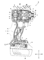
- FIG. 1 is a side view showing the appearance of the impact tool 1 according to the embodiment of the present invention.
- the impact tool 1 is a driver that uses a rechargeable pack-type battery 90 as a power source, applies a rotational force and a striking force to an output shaft (anvil 50) using a motor as a drive source, and is held in a mounting hole 53 by a mounting mechanism 60.
- Rotational striking force is intermittently transmitted to a tip tool (not shown) such as a bit to perform operations such as screw tightening and bolt tightening.
- the housing 2 of the impact tool 1 has a substantially cylindrical tubular body portion 2a for accommodating a motor and a power transmission mechanism, and a substantially cylindrical body portion 2a extending in a direction substantially orthogonal to the rotation axis A1 from the vicinity of the substantially center of the body portion 2a. It has a substantially T-shaped shape having a handle portion 2b for the operator to grip with one hand.
- a battery mounting portion 2c is formed at a lower end portion (anti-body portion side end portion) located on the opposite side of the body portion 2a from the end portions of the handle portion 2b.
- a trigger lever 7a is arranged so as to project forward in the upper part of the handle portion 2b, and forward / reverse switching for switching the rotation direction of the motor 3 in the forward direction or the reverse direction on the rear side of the trigger lever 7a.
- a lever 8 is provided.
- the motor 3 is housed on the rear side of the cylindrical body portion 2a.
- the motor 3 is a DC (direct current) motor without a brush (rectifying brush), and is a 4-pole 6-slot brushless DC motor.
- the motor 3 includes a rotor (rotor) 3a provided with a permanent magnet and a stator (stator) 3b provided with a multi-phase armature winding (stator winding) such as a three-phase winding.
- the rotor 3a forms a magnetic path formed by a permanent magnet.
- the stator 3b is manufactured by a laminated structure of an annular thin iron plate, and six teeth (not shown) are formed on the inner peripheral side, and an enamel wire is wound around each tooth to form a coil.
- the coil is a star connection or a delta connection having three phases of U, V, and W.
- the motor 3 uses the output of the position detection element 13 composed of a plurality of Hall ICs for detecting the magnetic force of the permanent magnet of the rotor 3a to detect the rotor position, and uses the output of the position detection element 13 to transmit the DC voltage supplied from the battery or the like to a plurality of semiconductors. It operates by being switched by the switching element 14.
- the motor is a brushless motor, but a motor with a brush may be used.
- the rotary shaft 4 of the motor 3 is arranged concentrically with the rotary axis A1 of the tubular body portion 2a, and is pivotally supported by the housing 2 by two bearings 16a and 16b on the front side and the rear side.
- a substantially annular inverter circuit board 12 for mounting three position detection elements 13, six semiconductor switching elements 14, and the like is arranged on the rear side of the stator 3b.
- the inverter circuit board 12 is a substantially annular double-sided board having a diameter substantially the same as the outer diameter of the motor 3.
- Six semiconductor switching elements 14 are provided to form an inverter circuit, and the energization of the stator windings of each phase is switched.
- a FET field effect transistor
- IGBT insulated gate bipolar transistor
- a cooling fan 15 is mounted coaxially with the rotating shaft 4 between the rotor 3a and the bearing 16b.
- the cooling fan 15 is integrally molded by, for example, a plastic mold, and sucks air from air intakes (not shown) formed near the left and right sides of the inverter circuit board 12 of the body portion 2a to suck air into the inside of the motor 3. And the air is discharged to the rear side in the direction of the rotation axis A1 so as to flow around.
- the cooling air that has passed through the inverter circuit board 12 cools the motor 3 located on the rear side of the inverter circuit board 12, and goes out from the air exhaust slit (not shown) formed on the side of the cooling fan 15. It is discharged.
- a cup-shaped hammer case 5 is provided on the front side of the housing 2.
- the hammer case 5 houses the deceleration mechanism 20 and the impact mechanism (impact mechanism) 25 inside, and is provided on the front side of the body portion 2a of the housing 2.
- the hammer case 5 is made of an integral metal product, and a through hole 5a for penetrating the anvil 50 is formed in a front portion corresponding to a cup-shaped bottom.
- a mounting mechanism 60 for mounting or removing a tip tool (not shown) is provided at the tip portion of the anvil 50.
- the mounting mechanism 60 is formed at two locations in the circumferential direction and has a hexagonal mounting hole 53 extending axially rearward from the front end of the anvil 50 and penetrates in the radial direction for arranging the steel balls 64. It includes two holes and a sleeve 61 provided on the outer peripheral side. A spring 62 that urges the sleeve 61 to the rear side is mounted on the inside of the sleeve 61.
- a lighting device 9 for illuminating the vicinity of the tip of a tip tool (not shown) is provided on the lower side of the mounting mechanism 60. As the lighting device 9, one or a plurality of LEDs (light emitting diodes) are used, and an irradiation window that transmits light is provided on the front side of the lighting device 9.
- a trigger lever 7a is arranged so as to project forward in the upper part of the handle portion 2b extending integrally from the body portion 2a of the housing 2 at a substantially right angle, and a trigger switch 7 is provided behind the trigger lever 7a.
- the user can adjust the trigger pushing amount (operation amount) and adjust the rotation speed of the motor 3 by grasping the handle portion 2b with one hand and pulling the trigger lever 7a backward with an index finger or the like.
- the rotation direction of the motor 3 can be switched by operating the forward / reverse switching lever 8.
- the lower portion of the handle portion 2b is provided with a battery mounting portion 2c whose diameter is expanded in a direction substantially orthogonal to the axial direction of the handle portion 2b.
- a battery 90 which is a drive power source for the motor 3, is detachably mounted on the battery mounting portion 2c. To remove the battery 90, the battery 90 is relatively moved forward from the main body of the impact tool 1 while pressing the latch portion 91.
- a control circuit board 70 for controlling the inverter circuit board 12 of the motor 3 is provided on the upper portion of the battery 90.
- the control circuit board 70 is horizontally arranged so as to extend in the front-back and left-right directions, and is equipped with a microcomputer (not shown) that controls the rotation of the motor 3.
- the control circuit board 70 is connected to the inverter circuit board 12 via a signal line.
- a switch panel for arranging a remaining amount check switch of the battery 90, an LED display device for displaying the remaining amount, and a lighting switch of the lighting device 9 on the upper surface of the battery mounting portion 2c in the vicinity of the control circuit board 70. 75 is provided.
- the body portion 2a of the housing 2 is manufactured by integrally molding a synthetic resin material together with the handle portion 2b and the battery mounting portion 2c, and is formed so as to be split into two left and right on a vertical surface passing through the rotation shaft 4 of the motor 3.
- the left side member and the right side member of the housing 2 are prepared, and the deceleration mechanism 20 and the impact mechanism 25 are incorporated in advance in one housing 2 (for example, the left housing) as shown in the cross-sectional view of FIG.
- a method is adopted in which the hammer case 5 and the motor 3 and the like are assembled, and then the other housing 2 (for example, the housing on the right side) is overlapped and tightened with a plurality of screws.
- the impact mechanism 25 is provided on the output side of the reduction mechanism 20 using planetary gears, includes a spindle 26 and a hammer 30, and is rotatably held by a bearing 18b at the rear end and a bearing 18a at the front end.
- the reduction mechanism 20 is provided in the space between the sun gear 21 fixed to the tip of the rotating shaft 4 of the motor 3, the ring gear 23 provided on the outer peripheral side of the sun gear 21 so as to surround the sun gear 21 at a distance, and the space between the sun gear 21 and the ring gear 23. It comprises a plurality of planetary gears 22 that are arranged and meshed with both of these gears.
- the ring gear 23 is also called an outer gear, and a gear is formed on the inner peripheral surface of the ring-shaped member. The outer peripheral surface of the ring gear 23 is held by the housing 2, and the ring gear 23 itself does not rotate.
- the sun gear 21 is a spur gear that serves as an input unit for the reduction mechanism 20.
- a plurality of (three in this case) planetary gears 22 are arranged between the outer peripheral side gear surface of the sun gear 21 and the inner peripheral side gear surface of the ring gear 23.
- the three planetary gears 22 are pivotally supported by a planetary carrier portion formed at the rear end of the spindle 26, and the planetary gears 22 rotate around a shaft (not shown) pivotally supported by the planetary carrier portion. While revolving around the sun gear 21.
- the sun gear 21 When the rotating shaft 4 of the motor 3 rotates, the sun gear 21 also rotates in synchronization with the rotation.
- the rotational force of the sun gear 21 is decelerated at a predetermined ratio to rotate the spindle 26.
- the inner cover 19 is a component manufactured by integrally molding a synthetic resin, and is held by the body portion 2a of the housing 2 so as to be sandwiched from the left-right direction. At this time, the inner cover 19 is held so as not to rotate relative to the housing 2. Since one of a plurality of screw bosses is located on the upper part of the inner cover 19, the inner cover 19 is stably sandwiched by the housing 2.
- the main role of the inner cover 19 is to hold the two bearings 18b and 16a provided, and to coaxially center the rotation axis 4 of the motor 3 and the rotation center of the spindle 26.
- the bearing 16a held by the inner cover 19 is for supporting the rotating shaft 4 of the motor 3, for example, a ball bearing is used.
- the bearing 18b held by the inner cover 19 is for pivotally supporting the rear end of the spindle 26, and for example, a ball bearing is used.
- the deceleration mechanism 20 and the impact mechanism 25 form a power transmission mechanism for driving the tip tool by the motor 3.
- the motor 3 starts rotating in the direction set by the forward / reverse switching lever 8, and the rotational force is decelerated by the deceleration mechanism 20 and transmitted to the spindle 26.
- the spindle 26 rotates at a predetermined speed.
- the spindle 26 and the hammer 30 are connected by a cam mechanism, and this cam mechanism is formed on the V-shaped spindle cam groove 26a formed on the outer peripheral surface of the spindle 26 and the inner peripheral surface of the hammer 30. It is composed of a hammer cam groove 39 and two steel balls 27 that engage the cam grooves 26a and 39.
- the hammer 30 is always urged forward by the hammer spring 28.
- the hammer 30 and the anvil 50 are hit at three points on the opposite rotation plane by the hammer claws (striking claws) 36 to 38 (37 cannot be seen in the figure) protruding convexly in the direction of the rotation axis A1 and the striking claws.
- the blade portions (hit claws) 56 to 58 are formed rotationally symmetrically.
- the striking claw of the hammer 30 gets over the impacted claw of the anvil 50 and the engagement between the two is released by the backward movement of the hammer 30, the hammer 30 accumulates in the hammer spring 28 in addition to the rotational force of the spindle 26. While being rapidly accelerated in the direction of rotation and forward by the action of the elastic energy and the cam mechanism, the hammer spring 28 moves forward by the urging force of the hammer spring 28, and the striking claw (36, etc.) of the hammer 30 becomes the impacted claw of the anvil 50. It engages again with (56 mag) and begins to rotate integrally.
- the number of hits becomes 3 times (low-speed hits) or 1.5 times (high-speed hits). Since the striking force is applied to the anvil 50, the rotational striking force is transmitted to a tip tool (not shown) mounted in the mounting hole 53 integrally formed with the anvil 50. After that, the same operation is repeated, and the rotational striking force is intermittently and repeatedly transmitted to the tip tool, and for example, a wood screw is screwed into a member to be tightened (not shown) such as wood.
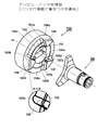
- FIG. 2 is a perspective view of the hammer 30 and the anvil 50 according to the present embodiment.
- the hammer 30 is arranged between the deceleration mechanism 20 in the direction along the rotation axis A1 and the anvil 50.
- the hammer 30 is configured to be relatively rotatable with respect to the spindle 26 (see FIG. 1) and relatively movable in the direction along the rotation axis A1.
- Hammer cam grooves 39a and 39b are formed inside the hammer 30 in the radial direction.
- Steel balls 27 (see FIG. 1) are arranged inside these hammer cam grooves 39a and 39b. Since the hammer 30 is held by the spindle 26 (see FIG. 1) via the steel ball 27 (see FIG.
- the hammer 30 can move in the direction along the rotation axis A1 within the range in which the steel ball 27 can roll.
- the steel ball 27 can rotate relative to the spindle 26 in a predetermined range in the circumferential direction with the rotation axis A1 as the central axis within a range in which the steel ball 27 can roll.
- the hammer claws 36 to 38 of the hammer 30 and the blade portions 56 to 58 of the anvil 50 repeatedly engage and disengage, thereby causing a rotational impact on the anvil 50 which is an output shaft. Force is generated.
- the weight of the hammer 30 is set to be larger than the weight of the anvil 50, and the hammer 30 converts the rotational force of the spindle 26 into the rotational force of the anvil 50 and the striking force in the rotational direction.
- the hammer 30 is composed of a main body portion 31 formed in a substantially cylindrical shape and hammer claws 36 to 38 extending forward from the main body portion 31.
- the portion of the hammer 30 other than the hammer claws 36 to 38 is defined as the “main body portion 31”.
- a front facing surface 32 orthogonal to the rotation axis A1 is formed on the anvil 50 side of the main body portion 31.
- the front facing surface 32 is a surface adjacent to and facing the anvil 50, and when the hammer 30 is in the normal position (the front position of the front-back movement range along the rotation axis A1), the blade portions 56 to 58 of the anvil 50 They face each other or come into contact with each other with a slight gap.
- the front facing surface 32 is a substantially annular surface orthogonal to the rotation axis A1.
- Tapered surfaces 34a to 34c are formed on the outer peripheral side of the front facing surface 32.
- the tapered surfaces 34a to 34c are inclined surfaces that incline toward the rear side (anti-anvil side) in the rotation axis A1 direction from the radial inner peripheral side to the outer peripheral side.
- the connection portion between the outer peripheral edge portion of the front facing surface 32 and the inner peripheral edge portion of the tapered surfaces 34a to 34c is shown as a double line, but this is a cross-sectional shape including the rotation axis A1 of the connection portion.
- the area between the double lines is formed as a surface having a small radius of curvature because of the chamfering process.
- the outer peripheral edge of the front facing surface 32 and the inner peripheral edge of the tapered surfaces 34a to 34c are angularized, the double lines are connected by a plane, or the double lines are inward in the plane direction. It is arbitrary whether the groove is dented.
- the hammer claws 36 to 38 are formed so as to project forward from the main body portion 31, and are integrally formed with the main body portion 31.
- the center positions of the hammer claws 36 to 38 in the circumferential direction are arranged at intervals of 120 degrees in the circumferential direction (equal intervals), and the cross-sectional shape along the direction intersecting the rotation axis A1 is substantially fan-shaped.
- the width dimension of the hammer claws 36 to 38 on the outer side in the radial direction of the hammer 30 and in the direction along the circumferential direction is set to about 10 mm.
- the strength of the hammer claws 36 to 38 is sufficiently secured, and the blade portions 56 to 58 of the anvil 50 can be inserted between the adjacent hammer claws 36 to 38 along the circumferential direction of the hammer 30 with a margin. ..
- the central angle portion of the substantially fan shape is located on the side close to the rotation axis A1, and the arc portion is located at substantially the same position as the outer edge position of the main body portion 31 of the hammer 30 or slightly inside.
- the arcuate portion may have the same diameter from the rear to the front in the rotation axis A1 direction, or may have a shape in which the diameter becomes slightly smaller.
- each outer peripheral surface of the hammer claws 36 to 38 is shaped so that the outer diameter on the tip side is slightly narrowed so that the diameter becomes slightly smaller toward the front. Further, the front end faces of the hammer claws 36 to 38 are chamfered so as to be orthogonal to the rotation axis A1. That is, the front end surface of the hammer claws 36 to 38 is a surface parallel to the front facing surface 32.
- the tapered surfaces 34a to 34c are arranged so as to be intermittent in the circumferential direction by three hammer claws 36 to 38 when viewed in the circumferential direction.
- the innermost peripheral position of each of the tapered surfaces 34a to 34c is arranged between the innermost position and the outermost position in the radial direction of the substantially fan-shaped hammer claws 36 to 38.
- the anvil 50 is manufactured by integral molding of metal, and three blade portions 56 to 58 radially outward from the annular flange portion 54 are formed on the rear side of the main shaft portion 51.
- the spindle portion 51 is a portion pivotally supported by a bearing 18a (see FIG. 1) using a needle bearing, and serves as a rolling surface of the needle of the bearing 18a.
- a small diameter portion 52 formed slightly narrower for mounting a tip tool mounting mechanism 60 (not shown) is formed on the front side of the spindle portion 51.
- a mounting hole 53 having a hexagonal cross section and for mounting a tip tool is formed from the tip of the small diameter portion 52 toward the rear side in the rotation axis A1 direction.
- Two through holes 52a penetrating in the radial direction are formed near the rear end of the small diameter portion 52, and a steel ball 64 (see FIG. 1) which is a component of the mounting mechanism 60 is arranged.
- the area between the through hole 52a and the blade portions 56 to 58 (the portion indicated by the arrow 61c) when viewed in the axial direction is a main shaft portion 51 having a columnar outer peripheral surface.
- the three blade portions 56 to 58 which are the impacted portions, are impacted claws that are evenly arranged so that their circumferential center positions are separated by 120 ° when viewed in the rotational direction, and extend outward in the radial direction. Be placed.
- the side surfaces of the blade portions 56 to 58 in the rotation direction are formed on the hit surfaces 56a, 57a, 58a that are hit by the hitting claws of the hammer 30 when rotating in the tightening direction, and are hit on the opposite sides thereof and are hit when rotating in the loosening direction.
- the hit surfaces 56b, 57b, 58b are formed.
- a columnar shaft portion 55 is formed on the rear side of the blade portions 56 to 58, and the outer peripheral surface of the shaft portion 55 is slidable by engaging with the fitting hole (see FIG. 1) of the spindle 26. It is supported by.
- the width dimension of the blade portions 56 to 58 on the outer side in the radial direction of the anvil 50 and in the direction along the circumferential direction is set to about 5 mm. That is, the width dimension is set to be slightly shorter than the hammer claws 36 to 38.
- the strength of the blade portions 56 to 58 is sufficiently secured, and the distance between the adjacent blade portions 56 to 58 along the circumferential direction of the anvil 50 is set to be a relatively long distance, and the hammer claw of the hammer 30 is set. 36-38 can enter with a margin.
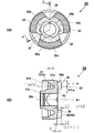
- FIG. 3A is a front view of the hammer 30, and a vertical sectional view of FIG. 3B is a sectional view taken along the line AA of FIG. 3A.
- the cross-sectional view of the part AA is used (note that the hammer 30 and the anvil are also shown in FIGS. 1 and 6).
- the cross-sectional position of 50 is a cross-section like the AA part).
- the front wall surface of the main body 31 of the hammer 30 is formed by a front facing surface 32 located on the inner peripheral side and tapered surfaces 34a, 34b, 34c located on the outer peripheral side thereof.
- the hammer claws 36, 37, and 38 are fan-shaped when viewed from the front.
- the root of the innermost peripheral position of the fan shape (the connection part with the main body 31) is within the range of the front facing surface 32, and the outer peripheral side is tapered surfaces 34a, 34b, 34c from the middle of the side portion on the straight line of the fan. It becomes the area to be joined with. That is, the boundary position 33 between the tapered surfaces 34a, 34b, 34c and the front facing surface 32 is located between the innermost position and the outermost position of the fan-shaped portion of the hammer claws 36, 37, 38. It is good to configure it to.
- the hammer 30 has a double cylindrical shape of an outer cylinder portion 31a and an inner cylinder portion 31c, and the outer cylinder portion 31a and the inner cylinder portion 31c are connected by a front connecting portion 31b on the front side thereof.
- a front facing surface 32 and tapered surfaces 34a to 34c are formed on the front side of the front connecting portion 31b.
- a spring supporting portion 31d for supporting the front end portion of the coiled spring in which the hammer spring 28 is held is formed.
- the center position (front end position) of the annular shape of the spring support portion 31d is such that the distance from the rotation axis A1 is substantially the same as the boundary position 33 between the tapered surfaces 34a to 34c and the orthogonal surface (front facing surface 32). It becomes a relationship.
- the lengths of the hammer claws 36, 37, and 38 in the rotation axis direction A1 become L1 on the inner peripheral side, L2 on the outer peripheral side, and the relationship L2> L1.
- the receding angle ⁇ of the tapered surfaces 34a and 34b is set to 6 ° here, but may be appropriately set in the range of about 2 ° to 20 °.
- FIG. 4A is a front view of the anvil 50.
- the shape of the anvil 50 is the same as that of the anvil 50 used in the conventional impact tool 1.
- the anvil 50 is attached at a position where the distance from the hammer 30 in the direction of the rotation axis A1 is slightly smaller than that of the conventional impact tool.
- the anvil 50 has three blades 56-58.
- the hitting surfaces 56a, 57a, 58a are formed on one side of the blade portions 56 to 58 in the rotation direction, and the hitting surfaces 56b, 57b, 58b are formed on the other side.
- annular flange portion 54 is formed on the outer peripheral side of the main shaft portion 51, and the front view shape of the flange portion 54 and the blade portions 56 to 58 is made to have a shape close to a triangle. Is increasing.
- FIG. 4B is a cross-sectional view taken along the line BB of FIG. 4A.
- the mounting hole 53 of the anvil 50 is configured to extend not only to the small diameter portion 52 but also to the inside of the main shaft portion 51 to the rear side in the rotation axis A1 direction. With this configuration, tip tools such as bits (not shown) can be mounted in the axial direction.
- the through hole 52a is a hole that penetrates from the inner mounting hole 53 of the small diameter portion 52 to the outside.
- the size of the through hole 52a is formed to be slightly larger than that of the steel ball 64 (see FIG. 1), but is the innermost.
- the steel ball 64 Since the steel ball 64 is formed to be slightly smaller than the steel ball 64 by the diameter of the position, the steel ball 64 inserted from the outer peripheral side of the through hole 52a cannot pass through the inside of the mounting hole 53 on the inner side in the radial direction, and the mounting hole 53 cannot be formed. It is formed so as to stay on the side with a certain amount of protrusion.
- a circumferential groove 52b continuous in the circumferential direction is formed in the vicinity of the tip of the small diameter portion 52 in the rotation axis A1 direction in order to fix the retaining ring 63 (see FIG. 1) for holding the spring 62 (see FIG. 1). Will be done.
- blade portions 56, 57, 58 (57 cannot be seen in the figure) extending radially outward from the flange portion 54 are formed, and more than the blade portions 56, 57, 58.
- a columnar shaft portion 55 is formed on the rear side.
- the shaft portion 55 is formed of solid material and is pivotally supported in a slidable state by engaging with a fitting hole (see FIG. 1) of the spindle 26.
- FIG. 5 is a front view showing a normal striking state of the hammer 30 and the anvil 50.
- the rotation centers of the hammer 30 and the anvil 50 are coaxial with the rotation axis A1 which is the rotation center of the motor 3 under normal conditions.
- the striking surface 36a of the hammer claw 36 and the striking surface 56a of the anvil 50 are in good surface contact with each other on substantially the entire surface as shown by the portion indicated by the thick black line.
- the striking surface 37a of the hammer claw 37 and the striking surface 57a of the anvil 50 are in good surface contact with each other on substantially the entire surface
- the striking surface 38a of the hammer claw 38 and the striking surface 58a of the anvil 50 are substantially in full surface. Good surface contact. Since these three surface contacts occur at the same time as the hammer 30 rotates during normal rotation, a rotationally symmetric striking force is transmitted from the hammer 30 to the anvil 50 with respect to the rotation axis A1.
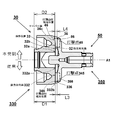
- FIG. 6 is a vertical cross section for comparing the shapes of the hammer 30 and the anvil 50
- the upper half of the rotation axis A1 is a diagram showing the shapes of the hammer 30 and the anvil 50 of the present invention
- the lower half is the conventional hammer 330. It is a figure which shows the shape of and 350.
- the outer wall surface (front facing surface 332) on the front side of the main body 331 is a surface perpendicular to the rotation axis A1 in the radial direction of the front facing surface 332.
- the radial inner position 32a to the boundary position 33 (up to the figure is a flat flat surface 32b (orthogonal surface) orthogonal to the rotation axis A1), and the outer peripheral side from the boundary position 33 is a tapered surface.
- 34a to 34c (the 34c portion is visible in the figure). Since the boundary position 33 is located inside the outermost diameter portion of the anvil 50, the outermost diameter portion of the anvil 50 is a tapered surface 34a to 34c.
- the distance between the striking point 45 by the hammer claw 36 of this embodiment and the main body portion 31 (root position 46) of the hammer 30 is L4 as shown in the figure.
- the distance between the striking point 345 by the hammer claw 336 and the main body portion 331 (root position 346) of the hammer 330 is L3 as shown in the figure, and the relationship is L4> L3.
- the flat surface 32b (orthogonal surface) and the tapered surfaces 34a to 34c are provided on the front side of the main body portion 31 of the hammer 30, the length in the axial direction from the flat surface 32b (orthogonal surface) of the hammer 30 to the rear end.
- the D1 can be configured to be larger than the axial length D2 from the tapered surfaces 34a to 34c of the hammer 30 to the rear end.
- the tapered surfaces 34a to 34c are formed on the outer peripheral side of the front side wall surface of the main body portion 31 of the hammer 30, but the tapered surfaces 34a to 34c have a cross-sectional shape as shown in FIG. It may be formed in an arc shape or a polygonal shape.
- FIG. 7A is a front view showing a striking state when the hammer 30 and the anvil 50 are misaligned.
- the impact of 38a and the impacted surface 58a occur at the same time.
- the center of rotation of the hammer 30 deviates from the center of rotation A3 of the anvil 50 as in A2
- the first impact point of the hammer 30 and the anvil 50 becomes point contact (or line contact) instead of surface contact.
- the timing of hitting is not at the same time in three places.
- FIG. 7A is a diagram showing an extremely large deviation between the rotation centers A2 and A3 in the description of the state. Note that some of the blades of the anvil 50 are omitted.
- FIG. 7A is an example in which the first hitting point becomes a specific point (the hitting point in the figure) of the hammer claw 36 and the blade portion 56 due to the deviation of the rotation center A2 of the hammer 30.
- the hammer 30 shift to the position of the rotation center A2 with respect to the rotation axis A1
- the rotation center A3 of the anvil 50 may shift in the opposite direction to the rotation axis A1.
- FIG. 7B shows a cross section of the CC portion in this state.
- FIG. 7B is a cross-sectional view of the CC portion and a view of the rotation axis A1 direction from the CC portion.
- the position of the blade portion 56 of the anvil 50 is indicated by the alternate long and short dash line.
- the hammer claw 36 is in contact with the blade portion 56 of the anvil 50 on the front side away from the chamfered groove 41a formed at the base of the hammer claw 36 in the direction of the rotation axis A1.
- the base of the hammer claw 36 and the blade portion 56 of the anvil 50 are separated from the state shown in FIG. 1 in the direction of the rotation axis A1 due to the rotation speed of the spindle 26, the load acting on the tip tool, and the like. It has become. That is, the striking point (line) shown in FIG. 7A is generated on the front side when viewed in the direction of the rotation axis A1.
- FIG. 8 is an enlarged view of a portion D in FIG. 7 (B).
- the claw portion of the hammer 30 (for example, the hammer claw 36) becomes the blade portion of the anvil 50 (for example, the blade portion). 56) hit.
- FIG. 8 shows the state immediately after the striking, in which the striking surface 36a of the hammer claw 36 collides with the blade portion 56 of the anvil 50 from the normal state (parallel to the rotating axis A1) shown by the alternate long and short dash line.
- the strain is distorted from the position of the alternate long and short dash line as shown on the striking surface 36a'shown by the solid line (for easy understanding, the strain is shown extremely large in FIG. 8, but the actual strain is extremely small).
- the distance from the tapered surface 34c seen in the direction of the rotation axis A1 to the striking point is L4 like the hammer claw 36, and the striking point is from the position of the striking surface 36a when not striking. Is displaced by d, and the striking surface 36a'of the hammer claw 36 is deformed by an angle ⁇ at the time of striking.
- the striking surface 36a of the hammer claw 36 and the striking surface 57a of the anvil 50 come into contact with each other on substantially the entire surface as shown in FIG.
- the position of the front facing surface 332 of the main body of the hammer is the position shown by the dotted line in FIG. Become.
- the distance from the dotted line position seen in the direction of the rotation axis A1 to the striking point is L3.
- the striking surface of the hammer claw 336 is deformed by the angle ⁇ at the time of striking, and the relationship is ⁇ ⁇ . That is, the stress generated in each of the hammer claws 36 to 38 is smaller in the shape to which the present invention is applied.
- the hammer 30 of this embodiment even when the hammer claw and the anvil blade are locally in contact with each other at the outer diameter side end portion, before a large stress is generated at the base of the contact portion of the hammer claw.
- the contact part expands to the inner diameter side, and the difference due to the position of the load borne by the base of the hammer nail can be reduced.
- the stress concentration near the outer diameter side end of the base of the nail, which occurs when the hammer nail hits one side is reduced, and a highly reliable and durable striking mechanism can be realized.
- FIG. 9 is a perspective view of the hammer 130 and the anvil 150 according to the second embodiment of the present invention.
- the hammer 130 includes a main body 131 and three hammer claws 136 to 138, and a flat surface (front facing surface 132) from the radial inner position of the main body 131 to the boundary position 133 is orthogonal to the rotation axis A1.
- the outer peripheral side is the tapered surface 134a to 134c from the boundary position 133.
- six groove portions 141a and 141b (not visible in the figure), 142a, 142b, 143a and 143b are formed.
- These grooves have a radius of curvature r, but by combining with the tapered surfaces 134a, 134b, 134c of this embodiment, the radius of curvature r can be made smaller than that of the groove formed in the conventional hammer 330. .. In FIG. 9, the radius of curvature r is exaggerated to a large extent for the purpose of understanding the explanation, but in reality, it is a very small radius of about 1 mm.
- the contact portion between the hammer 130 and the anvil 150, for overlaps the groove portion, constitutes a long axis of rotation A1 length of the hammer claw of the hammer 330
- the distance between the hammer 330 and the anvil 350 was widened.
- the size of the impact tool 1 can be made smaller than before.
- FIG. 10 is a perspective view of the hammer 230 and the anvil 250 according to the third embodiment of the present invention.
- the number of hammer claws and blades is three, but the present invention has two hammer claws of the hammer 230 as shown in FIG. ,
- the number of blades of the anvil 250 can be similarly realized with two impact tools.
- the hammer 230 includes a main body portion 231 and two hammer claws 236 and 237, and a flat surface (front facing surface 232) from the radial inner position of the main body portion 231 to the boundary position 233 is orthogonal to the rotation axis A1.
- the outer peripheral side becomes the tapered surface 234a and 234b from the boundary position 233.
- Two hammer claws 236 and 237 are arranged on the hammer 230 so as to be 180 ° apart in the circumferential direction.
- the hammer claw 236 has a substantially fan-shaped cross section orthogonal to the rotation axis A1, and a striking surface 236a at the time of normal rotation and a striking surface 236b at the time of reverse rotation are formed on the side surface in the circumferential direction.
- Connection portions 241a and 241b (241b cannot be seen in the figure) formed by a gentle curved surface are formed in the vicinity of the connection portion between the main body portion 231 and the striking surface 236a of the hammer 230, and the main body portion 231 and the striking surface 237b are formed.
- a connecting portion 242a formed of a gently curved surface is formed in the vicinity of the connecting portion. Further, the corners between the outer peripheral surface and the front surface of the hammer claw 236 are chamfered 241c, and the corners between the outer peripheral surface and the front surface of the hammer claw 237 are chamfered 242c.
- the two blade portions 256 and 257 are arranged so as to be separated from each other by 180 ° in the circumferential direction.
- the shapes of the spindle portion 51, the small diameter portion 52, the mounting hole 53, and the shaft portion 55 of the anvil 250 are the same as those of the anvil 50 of the first embodiment.
- the shape of the outer half of the blade portions 256 and 257 when viewed in the radial direction is the same as the outer shape of the blade portions 56 to 58 of the anvil 50 shown in the first embodiment.
- a hit surface 256a during forward rotation and a hit surface 256b during reverse rotation are formed on the side surface of the blade portion 256, and a hit surface 257a during forward rotation and a hit surface during reverse rotation are formed on the side surface of the blade portion 257.
- the surface 257b is formed.
- the present invention can be applied to an impact tool having two hammer claws and blades.
- the present invention has been described above based on the examples, the present invention is not limited to the above-mentioned examples, and various modifications can be made without departing from the spirit of the present invention.
- the shape of the hammer claw of the hammer and the shape of the blade portion of the anvil are not limited to the above-mentioned examples, and may be realized by other shapes.
- the outer peripheral portion of the surface located on the front side of the main body of the hammer is formed in a tapered shape so that the length of the hammer claw in the rotation axis direction differs between the inner peripheral side and the outer peripheral side. Is also good.
- the tapered surface is not formed as a flat surface, but may be an arc surface having a convex shape on the outside, or may be a polyhedral shape.
- ring gear 25 ... impact mechanism, 26 ... spindle, 26a ... spindle cam groove, 27 ... Steel ball, 28 ... Hammer spring, 30 ... Hammer, 31 ... Main body, 31a ... Outer cylinder, 31b ... Front connection, 31c ... Inner cylinder, 31d ... Spring support, 32 ... Front facing surface, 32a ... (front facing surface) radial inner position, 32b ... flat surface (orthogonal surface), 33 ... boundary position, 34a-34c ... tapered surface, 36,37,38 ... hammer claw, 36a, 37a, 38a ... striking surface (At the time of forward rotation), 36b, 37b, 38b ...
Landscapes
- Engineering & Computer Science (AREA)
- Mechanical Engineering (AREA)
- Percussive Tools And Related Accessories (AREA)
- Portable Power Tools In General (AREA)
Priority Applications (4)
| Application Number | Priority Date | Filing Date | Title |
|---|---|---|---|
| JP2022527599A JP7472975B2 (ja) | 2020-05-29 | 2021-04-23 | インパクト工具 |
| US17/927,747 US12290901B2 (en) | 2020-05-29 | 2021-04-23 | Impact tool |
| CN202180038133.6A CN115666861B (zh) | 2020-05-29 | 2021-04-23 | 冲击工具 |
| EP21813492.2A EP4159375A4 (en) | 2020-05-29 | 2021-04-23 | PERCUSSION TOOL |
Applications Claiming Priority (2)
| Application Number | Priority Date | Filing Date | Title |
|---|---|---|---|
| JP2020094019 | 2020-05-29 | ||
| JP2020-094019 | 2020-05-29 |
Publications (1)
| Publication Number | Publication Date |
|---|---|
| WO2021241099A1 true WO2021241099A1 (ja) | 2021-12-02 |
Family
ID=78745189
Family Applications (1)
| Application Number | Title | Priority Date | Filing Date |
|---|---|---|---|
| PCT/JP2021/016543 Ceased WO2021241099A1 (ja) | 2020-05-29 | 2021-04-23 | インパクト工具 |
Country Status (5)
| Country | Link |
|---|---|
| US (1) | US12290901B2 (https=) |
| EP (1) | EP4159375A4 (https=) |
| JP (1) | JP7472975B2 (https=) |
| CN (1) | CN115666861B (https=) |
| WO (1) | WO2021241099A1 (https=) |
Cited By (3)
| Publication number | Priority date | Publication date | Assignee | Title |
|---|---|---|---|---|
| JP2023181599A (ja) * | 2022-06-13 | 2023-12-25 | 株式会社マキタ | インパクト工具 |
| GB2630470A (en) * | 2021-07-09 | 2024-11-27 | Snap On Incorporated | Impact tool with tapered anvil wing design |
| WO2025225192A1 (ja) * | 2024-04-22 | 2025-10-30 | パナソニック株式会社 | 電動工具システム、及びアタッチメント |
Families Citing this family (3)
| Publication number | Priority date | Publication date | Assignee | Title |
|---|---|---|---|---|
| JP7462276B2 (ja) * | 2021-06-28 | 2024-04-05 | パナソニックIpマネジメント株式会社 | インパクト工具 |
| JP7826130B2 (ja) * | 2022-06-27 | 2026-03-09 | 株式会社マキタ | 電動作業機 |
| CN117506799A (zh) * | 2023-11-24 | 2024-02-06 | 苏州锐霸工具有限公司 | 一种大功率高寿命冲击结构以及应用其的冲击扳手 |
Citations (3)
| Publication number | Priority date | Publication date | Assignee | Title |
|---|---|---|---|---|
| JP2005254374A (ja) * | 2004-03-10 | 2005-09-22 | Makita Corp | インパクトドライバ |
| JP2008535675A (ja) * | 2005-04-13 | 2008-09-04 | セムブレ エス.ピー.エー. | インパクトレンチのインパクト機構 |
| WO2016002539A1 (ja) | 2014-06-30 | 2016-01-07 | 日立工機株式会社 | 打撃工具 |
Family Cites Families (19)
| Publication number | Priority date | Publication date | Assignee | Title |
|---|---|---|---|---|
| JP4643298B2 (ja) * | 2005-02-14 | 2011-03-02 | 株式会社マキタ | 打撃工具 |
| JP2009226568A (ja) | 2008-03-25 | 2009-10-08 | Makita Corp | 打撃工具 |
| JP4674640B2 (ja) * | 2009-01-27 | 2011-04-20 | パナソニック電工株式会社 | インパクト回転工具 |
| JP5284898B2 (ja) * | 2009-07-21 | 2013-09-11 | 株式会社マキタ | 打撃工具 |
| JP5340881B2 (ja) * | 2009-10-16 | 2013-11-13 | 株式会社マキタ | 打撃工具 |
| JP6027946B2 (ja) * | 2013-06-12 | 2016-11-16 | パナソニック株式会社 | インパクトレンチ |
| JP2015024474A (ja) * | 2013-07-26 | 2015-02-05 | 日立工機株式会社 | インパクト工具 |
| JP6198515B2 (ja) * | 2013-08-08 | 2017-09-20 | 株式会社マキタ | インパクト工具 |
| EP3175954B1 (en) * | 2014-07-31 | 2020-12-02 | Koki Holdings Co., Ltd. | Impact tool |
| US10654153B2 (en) * | 2015-01-30 | 2020-05-19 | Koki Holdings Co., Ltd. | Impact tool |
| JP6638522B2 (ja) * | 2015-08-07 | 2020-01-29 | 工機ホールディングス株式会社 | 電動工具 |
| CN110382167B (zh) * | 2017-03-07 | 2021-11-05 | 株式会社牧田 | 工具保持装置及电动工具、冲击工具 |
| JP6832509B2 (ja) * | 2017-03-27 | 2021-02-24 | パナソニックIpマネジメント株式会社 | 回転打撃工具 |
| JP6901898B2 (ja) * | 2017-04-17 | 2021-07-14 | 株式会社マキタ | 回転打撃工具 |
| JP6987667B2 (ja) * | 2018-02-23 | 2022-01-05 | 株式会社マキタ | インパクト工具 |
| JP6979605B2 (ja) * | 2018-05-11 | 2021-12-15 | パナソニックIpマネジメント株式会社 | インパクト回転工具 |
| US11351663B2 (en) * | 2019-12-24 | 2022-06-07 | Ingersoll-Rand Industrial U.S., Inc. | Latching hammer impact wrench |
| US11980948B2 (en) * | 2019-12-26 | 2024-05-14 | Koki Holdings Co., Ltd. | Rotary tool |
| JP7664047B2 (ja) * | 2021-01-06 | 2025-04-17 | 株式会社マキタ | インパクト工具 |
-
2021
- 2021-04-23 EP EP21813492.2A patent/EP4159375A4/en active Pending
- 2021-04-23 JP JP2022527599A patent/JP7472975B2/ja active Active
- 2021-04-23 US US17/927,747 patent/US12290901B2/en active Active
- 2021-04-23 CN CN202180038133.6A patent/CN115666861B/zh active Active
- 2021-04-23 WO PCT/JP2021/016543 patent/WO2021241099A1/ja not_active Ceased
Patent Citations (3)
| Publication number | Priority date | Publication date | Assignee | Title |
|---|---|---|---|---|
| JP2005254374A (ja) * | 2004-03-10 | 2005-09-22 | Makita Corp | インパクトドライバ |
| JP2008535675A (ja) * | 2005-04-13 | 2008-09-04 | セムブレ エス.ピー.エー. | インパクトレンチのインパクト機構 |
| WO2016002539A1 (ja) | 2014-06-30 | 2016-01-07 | 日立工機株式会社 | 打撃工具 |
Non-Patent Citations (1)
| Title |
|---|
| See also references of EP4159375A4 |
Cited By (5)
| Publication number | Priority date | Publication date | Assignee | Title |
|---|---|---|---|---|
| GB2630470A (en) * | 2021-07-09 | 2024-11-27 | Snap On Incorporated | Impact tool with tapered anvil wing design |
| US12257685B2 (en) | 2021-07-09 | 2025-03-25 | Snap-On Incorporated | Impact tool with tapered anvil wing design |
| GB2630470B (en) * | 2021-07-09 | 2025-04-23 | Snap On Incorporated | Impact tool with tapered anvil wing design |
| JP2023181599A (ja) * | 2022-06-13 | 2023-12-25 | 株式会社マキタ | インパクト工具 |
| WO2025225192A1 (ja) * | 2024-04-22 | 2025-10-30 | パナソニック株式会社 | 電動工具システム、及びアタッチメント |
Also Published As
| Publication number | Publication date |
|---|---|
| CN115666861B (zh) | 2025-08-29 |
| US20230202004A1 (en) | 2023-06-29 |
| CN115666861A (zh) | 2023-01-31 |
| US12290901B2 (en) | 2025-05-06 |
| JPWO2021241099A1 (https=) | 2021-12-02 |
| EP4159375A4 (en) | 2023-12-20 |
| EP4159375A1 (en) | 2023-04-05 |
| JP7472975B2 (ja) | 2024-04-23 |
Similar Documents
| Publication | Publication Date | Title |
|---|---|---|
| WO2021241099A1 (ja) | インパクト工具 | |
| JP5483086B2 (ja) | インパクト工具 | |
| US10040178B2 (en) | Power tool and rotary impact tool | |
| JP2015024474A (ja) | インパクト工具 | |
| US20150083451A1 (en) | Power tool | |
| JP5483089B2 (ja) | インパクト工具 | |
| EP2509752B1 (en) | Impact tool | |
| CN102781630B (zh) | 冲击工具 | |
| JP6638522B2 (ja) | 電動工具 | |
| JP5333719B2 (ja) | 電動工具 | |
| JP5190774B2 (ja) | 電動工具 | |
| JP5621980B2 (ja) | インパクト工具 | |
| WO2021241111A1 (ja) | 締め付け工具 | |
| JP6863415B2 (ja) | 電動工具 | |
| JP5648970B2 (ja) | インパクト工具 | |
| JP5556218B2 (ja) | インパクト工具 | |
| JP2022019061A (ja) | インパクト工具 | |
| JP2011031313A (ja) | インパクト工具 | |
| JP7459747B2 (ja) | インパクト工具 | |
| JP2011189412A (ja) | インパクト工具 | |
| JP2014240120A (ja) | 電動工具 | |
| JP2012157925A (ja) | 電動工具 | |
| JP6638856B2 (ja) | ねじ締め工具 | |
| WO2024020476A1 (en) | Outer ring drive planetary gear assembly | |
| JP2012232365A (ja) | インパクト工具 |
Legal Events
| Date | Code | Title | Description |
|---|---|---|---|
| 121 | Ep: the epo has been informed by wipo that ep was designated in this application |
Ref document number: 21813492 Country of ref document: EP Kind code of ref document: A1 |
|
| ENP | Entry into the national phase |
Ref document number: 2022527599 Country of ref document: JP Kind code of ref document: A |
|
| NENP | Non-entry into the national phase |
Ref country code: DE |
|
| ENP | Entry into the national phase |
Ref document number: 2021813492 Country of ref document: EP Effective date: 20230102 |
|
| WWG | Wipo information: grant in national office |
Ref document number: 17927747 Country of ref document: US |
|
| WWG | Wipo information: grant in national office |
Ref document number: 202180038133.6 Country of ref document: CN |