WO2021234809A1 - 基板収納容器 - Google Patents
基板収納容器 Download PDFInfo
- Publication number
- WO2021234809A1 WO2021234809A1 PCT/JP2020/019740 JP2020019740W WO2021234809A1 WO 2021234809 A1 WO2021234809 A1 WO 2021234809A1 JP 2020019740 W JP2020019740 W JP 2020019740W WO 2021234809 A1 WO2021234809 A1 WO 2021234809A1
- Authority
- WO
- WIPO (PCT)
- Prior art keywords
- lid
- substrate
- container body
- closed
- support portion
- Prior art date
- Legal status (The legal status is an assumption and is not a legal conclusion. Google has not performed a legal analysis and makes no representation as to the accuracy of the status listed.)
- Ceased
Links
Images





Classifications
-
- H—ELECTRICITY
- H10—SEMICONDUCTOR DEVICES; ELECTRIC SOLID-STATE DEVICES NOT OTHERWISE PROVIDED FOR
- H10P—GENERIC PROCESSES OR APPARATUS FOR THE MANUFACTURE OR TREATMENT OF DEVICES COVERED BY CLASS H10
- H10P72/00—Handling or holding of wafers, substrates or devices during manufacture or treatment thereof
- H10P72/30—Handling or holding of wafers, substrates or devices during manufacture or treatment thereof for conveying, e.g. between different workstations
- H10P72/34—Handling or holding of wafers, substrates or devices during manufacture or treatment thereof for conveying, e.g. between different workstations the wafers being stored in a carrier, involving loading and unloading
- H10P72/3404—Storage means
-
- B—PERFORMING OPERATIONS; TRANSPORTING
- B65—CONVEYING; PACKING; STORING; HANDLING THIN OR FILAMENTARY MATERIAL
- B65D—CONTAINERS FOR STORAGE OR TRANSPORT OF ARTICLES OR MATERIALS, e.g. BAGS, BARRELS, BOTTLES, BOXES, CANS, CARTONS, CRATES, DRUMS, JARS, TANKS, HOPPERS, FORWARDING CONTAINERS; ACCESSORIES, CLOSURES, OR FITTINGS THEREFOR; PACKAGING ELEMENTS; PACKAGES
- B65D85/00—Containers, packaging elements or packages, specially adapted for particular articles or materials
- B65D85/30—Containers, packaging elements or packages, specially adapted for particular articles or materials for articles particularly sensitive to damage by shock or pressure
-
- H—ELECTRICITY
- H10—SEMICONDUCTOR DEVICES; ELECTRIC SOLID-STATE DEVICES NOT OTHERWISE PROVIDED FOR
- H10P—GENERIC PROCESSES OR APPARATUS FOR THE MANUFACTURE OR TREATMENT OF DEVICES COVERED BY CLASS H10
- H10P72/00—Handling or holding of wafers, substrates or devices during manufacture or treatment thereof
- H10P72/10—Handling or holding of wafers, substrates or devices during manufacture or treatment thereof using carriers specially adapted therefor, e.g. front opening unified pods [FOUP]
- H10P72/19—Handling or holding of wafers, substrates or devices during manufacture or treatment thereof using carriers specially adapted therefor, e.g. front opening unified pods [FOUP] closed carriers
- H10P72/1911—Handling or holding of wafers, substrates or devices during manufacture or treatment thereof using carriers specially adapted therefor, e.g. front opening unified pods [FOUP] closed carriers characterised by materials, roughness, coatings or the like
- H10P72/1912—Handling or holding of wafers, substrates or devices during manufacture or treatment thereof using carriers specially adapted therefor, e.g. front opening unified pods [FOUP] closed carriers characterised by materials, roughness, coatings or the like characterised by shock absorbing elements, e.g. retainers or cushions
-
- H—ELECTRICITY
- H10—SEMICONDUCTOR DEVICES; ELECTRIC SOLID-STATE DEVICES NOT OTHERWISE PROVIDED FOR
- H10P—GENERIC PROCESSES OR APPARATUS FOR THE MANUFACTURE OR TREATMENT OF DEVICES COVERED BY CLASS H10
- H10P72/00—Handling or holding of wafers, substrates or devices during manufacture or treatment thereof
- H10P72/10—Handling or holding of wafers, substrates or devices during manufacture or treatment thereof using carriers specially adapted therefor, e.g. front opening unified pods [FOUP]
- H10P72/19—Handling or holding of wafers, substrates or devices during manufacture or treatment thereof using carriers specially adapted therefor, e.g. front opening unified pods [FOUP] closed carriers
- H10P72/1914—Handling or holding of wafers, substrates or devices during manufacture or treatment thereof using carriers specially adapted therefor, e.g. front opening unified pods [FOUP] closed carriers characterised by locking systems
-
- H—ELECTRICITY
- H10—SEMICONDUCTOR DEVICES; ELECTRIC SOLID-STATE DEVICES NOT OTHERWISE PROVIDED FOR
- H10P—GENERIC PROCESSES OR APPARATUS FOR THE MANUFACTURE OR TREATMENT OF DEVICES COVERED BY CLASS H10
- H10P72/00—Handling or holding of wafers, substrates or devices during manufacture or treatment thereof
- H10P72/10—Handling or holding of wafers, substrates or devices during manufacture or treatment thereof using carriers specially adapted therefor, e.g. front opening unified pods [FOUP]
- H10P72/19—Handling or holding of wafers, substrates or devices during manufacture or treatment thereof using carriers specially adapted therefor, e.g. front opening unified pods [FOUP] closed carriers
- H10P72/1918—Handling or holding of wafers, substrates or devices during manufacture or treatment thereof using carriers specially adapted therefor, e.g. front opening unified pods [FOUP] closed carriers characterised by coupling elements, kinematic members, handles or elements to be externally gripped
-
- H—ELECTRICITY
- H10—SEMICONDUCTOR DEVICES; ELECTRIC SOLID-STATE DEVICES NOT OTHERWISE PROVIDED FOR
- H10P—GENERIC PROCESSES OR APPARATUS FOR THE MANUFACTURE OR TREATMENT OF DEVICES COVERED BY CLASS H10
- H10P72/00—Handling or holding of wafers, substrates or devices during manufacture or treatment thereof
- H10P72/10—Handling or holding of wafers, substrates or devices during manufacture or treatment thereof using carriers specially adapted therefor, e.g. front opening unified pods [FOUP]
- H10P72/19—Handling or holding of wafers, substrates or devices during manufacture or treatment thereof using carriers specially adapted therefor, e.g. front opening unified pods [FOUP] closed carriers
- H10P72/1921—Handling or holding of wafers, substrates or devices during manufacture or treatment thereof using carriers specially adapted therefor, e.g. front opening unified pods [FOUP] closed carriers characterised by substrate supports
-
- H—ELECTRICITY
- H10—SEMICONDUCTOR DEVICES; ELECTRIC SOLID-STATE DEVICES NOT OTHERWISE PROVIDED FOR
- H10P—GENERIC PROCESSES OR APPARATUS FOR THE MANUFACTURE OR TREATMENT OF DEVICES COVERED BY CLASS H10
- H10P72/00—Handling or holding of wafers, substrates or devices during manufacture or treatment thereof
- H10P72/10—Handling or holding of wafers, substrates or devices during manufacture or treatment thereof using carriers specially adapted therefor, e.g. front opening unified pods [FOUP]
- H10P72/19—Handling or holding of wafers, substrates or devices during manufacture or treatment thereof using carriers specially adapted therefor, e.g. front opening unified pods [FOUP] closed carriers
- H10P72/1922—Handling or holding of wafers, substrates or devices during manufacture or treatment thereof using carriers specially adapted therefor, e.g. front opening unified pods [FOUP] closed carriers characterised by the construction of the closed carrier
-
- H—ELECTRICITY
- H10—SEMICONDUCTOR DEVICES; ELECTRIC SOLID-STATE DEVICES NOT OTHERWISE PROVIDED FOR
- H10P—GENERIC PROCESSES OR APPARATUS FOR THE MANUFACTURE OR TREATMENT OF DEVICES COVERED BY CLASS H10
- H10P72/00—Handling or holding of wafers, substrates or devices during manufacture or treatment thereof
- H10P72/30—Handling or holding of wafers, substrates or devices during manufacture or treatment thereof for conveying, e.g. between different workstations
- H10P72/33—Handling or holding of wafers, substrates or devices during manufacture or treatment thereof for conveying, e.g. between different workstations into and out of processing chamber
- H10P72/3302—Mechanical parts of transfer devices
-
- H—ELECTRICITY
- H10—SEMICONDUCTOR DEVICES; ELECTRIC SOLID-STATE DEVICES NOT OTHERWISE PROVIDED FOR
- H10P—GENERIC PROCESSES OR APPARATUS FOR THE MANUFACTURE OR TREATMENT OF DEVICES COVERED BY CLASS H10
- H10P72/00—Handling or holding of wafers, substrates or devices during manufacture or treatment thereof
- H10P72/30—Handling or holding of wafers, substrates or devices during manufacture or treatment thereof for conveying, e.g. between different workstations
- H10P72/34—Handling or holding of wafers, substrates or devices during manufacture or treatment thereof for conveying, e.g. between different workstations the wafers being stored in a carrier, involving loading and unloading
- H10P72/3402—Mechanical parts of transfer devices
Definitions
- the present invention relates to a substrate storage container used for storing, storing, transporting, transporting, etc. a substrate made of a semiconductor wafer or the like.
- Patent Document 1 As a substrate storage container for storing and transporting a substrate made of a semiconductor wafer, a container having a container body and a wafer carrier has been conventionally known (see, for example, Patent Document 1).
- One end of the container body has an opening peripheral portion on which the container body opening is formed.
- the other end of the container body has a closed tubular wall.
- a substrate storage space is formed in the container body.
- the board storage space is formed by being surrounded by a wall portion, and can store a plurality of boards.
- the lid is removable from the peripheral edge of the opening and can close the opening of the container body.
- the side substrate support portions are provided on the wall portion so as to form a pair in the substrate storage space.
- the side substrate support can support the edges of a plurality of substrates in a state where adjacent substrates are separated from each other at predetermined intervals and arranged in parallel when the opening of the container body is not closed by the lid. be.
- a front retainer is provided in the part of the lid that faces the board storage space when the opening of the container body is closed.
- the front retainer has a lid-side substrate receiving portion that directly contacts the substrate and supports the substrate, and a lid-side leg that supports the lid-side substrate receiving portion, and the container body opening is closed by the lid. It is possible to support the edges of multiple substrates when
- a back board support portion is provided on the wall portion so as to be paired with the front retainer.
- the back board support portion can support the edges of a plurality of boards.
- the back-side substrate support portion supports a plurality of substrates in cooperation with the front retainer to separate adjacent substrates at predetermined intervals. Hold multiple boards in parallel.
- the back board support portion cooperates with the front retainer to sandwich a plurality of boards in order to suppress damage and rotation of the board.
- a plurality of substrates are held and fixed in a state where adjacent substrates are separated from each other at a predetermined interval and arranged in parallel.
- the coefficient of friction of the material that constitutes the back board support is low, even if the board is held with a strong force, the board will rotate due to vibration during transportation of the board storage container, and stains due to the generation of particles will occur. Is easy to generate. Further, when the friction coefficient of the material constituting the back side substrate support portion is high, even if the substrate is held with a light force, the substrate is difficult to rotate due to vibration during transportation and the like, and there is little dirt due to the generation of particles.
- the container body opening is not closed by the lid from the container body opening is not closed by the lid.
- the edge of the substrate is with respect to the back side substrate support portion. Therefore, there is a problem that the substrate cannot be slid smoothly, the substrate cannot be moved to a predetermined position where the substrate is removed, and the substrate cannot be automatically taken out by the substrate transfer machine.
- the present invention provides a substrate storage container that can be reliably moved to a predetermined position from which the substrate is removed, that the substrate can be automatically taken out by a substrate transfer machine, and that is less contaminated by the generation of particles. With the goal.
- the present invention has an opening peripheral portion in which an opening of a container body is formed at one end, and has a tubular wall portion in which the other end is closed, and a plurality of substrates can be stored by the inner surface of the wall portion.
- a container body having a substrate storage space communicating with the container body opening, a lid that can be attached to and detached from the container body opening, and a lid that can close the container body opening, and the lid.
- the lid-side substrate support portion capable of supporting the edges of the plurality of substrates is arranged so as to be paired with the lid-side substrate support portion in the substrate storage space, and the edge portions of the plurality of substrates can be supported.
- the back side that supports the plurality of substrates in a state of cooperating with the lid side substrate support portion and arranging the plurality of substrates in parallel.
- a substrate support portion is provided, and the back-side substrate support portion is connected to a first contact portion having a first contact surface capable of contacting an edge of the surface of the substrate and the first contact surface.
- the present invention relates to a substrate storage container which is composed of an alloy resin mainly composed of a resin and has a mass composition in which the mass of a polybutylene terephthalate resin is larger than the mass of a polycarbonate resin.
- the material constituting the back side substrate support portion contains polybutylene terephthalate resin in an amount of 51% by mass or more with respect to the mass of the alloy resin.
- the back side substrate support portion is composed of an alloy resin mainly composed of a polycarbonate resin and a polybutylene terephthalate resin, and a polybutylene terephthalate resin having a mass of 51% by mass or more and less than 90% by mass with respect to the mass of the alloy resin is used. It is preferable to include it.
- the back side substrate support portion is provided with a side substrate support portion capable of supporting the edges of the plurality of substrates in a parallel state. It is preferable to support the plurality of substrates in a state in which the edges of the plurality of substrates are separated from the side substrate support portions and arranged in parallel in cooperation with the lid side substrate support portion.
- the substrate when the opening of the container body is closed by the lid, it is preferable to support the substrate so that the edge of the substrate is sandwiched between the first contact surface and the second contact surface. ..
- the present invention it is possible to provide a substrate storage container that can be reliably moved to a predetermined position from which the substrate is removed and that the substrate can be automatically taken out by a substrate transfer machine.
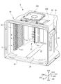
- FIG. 5 is an exploded perspective view showing a state in which a plurality of substrates W are stored in the substrate storage container 1 according to the embodiment of the present invention. It is a perspective view which shows the container main body 2 of the substrate storage container 1 which concerns on embodiment of this invention.
- FIG. 5 is an exploded perspective view showing a state in which one substrate W is stored in the container body 2 of the substrate storage container 1 according to the embodiment of the present invention. It is a perspective view which shows the cover body 3 of the substrate storage container 1 which concerns on embodiment of this invention. It is sectional drawing which shows the substrate storage container 1 which concerns on embodiment of this invention.
- FIG. 5 is an exploded perspective view showing a state in which a plurality of substrates W are stored in the substrate storage container 1 according to the embodiment of the present invention. It is a perspective view which shows the container main body 2 of the substrate storage container 1 which concerns on embodiment of this invention.
- FIG. 5 is an exploded perspective view showing a state in which one substrate W is stored in the container body 2 of the substrate
- FIG. 5 is an enlarged cross-sectional view showing a positional relationship between a back-side substrate support portion 6 and a substrate W in a state where the container body opening 21 is closed by the lid 3 of the substrate storage container 1 according to the embodiment of the present invention.
- PBT Polybutylene terephthalate resin
- PC polycarbonate resin
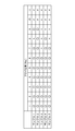
- the substrate W is automatically taken out by the substrate transfer machine. It is a table which shows the result of whether or not it was able to slide to a position where it is possible.
- the stains due to the generation of particles are within the standard range. It is a table showing the result of whether or not.
- FIG. 1 is an exploded perspective view showing a state in which a plurality of substrates W are stored in the substrate storage container 1 according to the embodiment of the present invention.
- FIG. 2 is a perspective view showing a container body 2 of the substrate storage container 1 according to the embodiment of the present invention.
- FIG. 3 is an exploded perspective view showing a state in which one substrate W is stored in the container body 2 of the substrate storage container 1 according to the embodiment of the present invention.
- FIG. 4 is a perspective view showing a lid 3 of the substrate storage container 1 according to the embodiment of the present invention.
- the direction from the container body 2 to the lid 3 (the direction from the upper right to the lower left in FIG. 1) is defined as the front direction D11, and the opposite direction is defined as the rear direction D12. These are collectively defined as the front-back direction D1.
- the direction from the lower wall 24 to the upper wall 23 (upward in FIG. 1), which will be described later, is defined as the upward direction D21, and the opposite direction is defined as the downward direction D22, which are collectively referred to as the vertical direction D2.
- the direction from the second side wall 26 to the first side wall 25 (the direction from the lower right to the upper left in FIG. 1), which will be described later, is defined as the left direction D31, and the opposite direction is defined as the right direction D32. Is also defined as the left-right direction D3.
- the main drawings show arrows pointing in these directions.
- the substrate W (see FIG. 1) stored in the substrate storage container 1 is a disk-shaped silicon wafer, a glass wafer, a sapphire wafer, or the like, and is a thin one used in industry.
- the substrate W in this embodiment is a silicon wafer having a diameter of 300 mm.
- the substrate storage container 1 is a shipping container for accommodating a substrate W made of a silicon wafer as described above and transporting the substrate W by transportation means such as land transportation means, air transportation means, and shipping means. It is used as a container body 2 and a lid body 3.
- the container body 2 includes a substrate support plate-shaped portion 5 as a side substrate support portion and a back side substrate support portion 6 (see FIG. 2 and the like), and the lid 3 serves as a lid side substrate support portion. It is equipped with a front retainer 7 (see FIG. 4, etc.).
- the container body 2 has a cylindrical wall portion 20 having a container body opening 21 formed at one end and a closed end.
- a substrate storage space 27 is formed in the container body 2.
- the board storage space 27 is formed by being surrounded by the wall portion 20.
- a substrate support plate-shaped portion 5 is arranged in a portion of the wall portion 20 that forms the substrate storage space 27. As shown in FIG. 1, a plurality of boards W can be stored in the board storage space 27.
- the board support plate-shaped portion 5 is provided on the wall portion 20 so as to form a pair in the board storage space 27.
- the substrate support plate-shaped portion 5 abuts on the edges of a plurality of substrates W to separate adjacent substrates W from each other at predetermined intervals. It is possible to support the edges of a plurality of substrates W in a parallel state.
- a back side board support portion 6 is provided on the back side of the board support plate-shaped portion 5.
- the back side board support portion 6 is provided on the wall portion 20 so as to be paired with the front retainer 7 described later in the board storage space 27.
- the back-side substrate support portion 6 can support the rear portions of the edges of the plurality of substrates W by abutting against the edges of the plurality of substrates W. Is.
- the lid 3 is removable from the opening peripheral edge 28 (FIG. 1 and the like) forming the container body opening 21, and the container body opening 21 can be closed.
- the front retainer 7 is provided in a portion of the lid 3 that faces the substrate storage space 27 when the container body opening 21 is closed by the lid 3.
- the front retainer 7 is arranged so as to be paired with the back side board support portion 6 inside the board storage space 27.
- the front retainer 7 can support the front portion of the edge portion of the plurality of substrates W by abutting on the edge portion of the plurality of substrates W when the container body opening 21 is closed by the lid body 3.
- the front retainer 7 supports a plurality of substrates W in cooperation with the back-side substrate support portion 6, thereby designating adjacent substrates W to each other.
- a plurality of substrates W are held in a state of being spaced apart from each other and arranged in parallel.
- the substrate storage container 1 is made of a resin such as a plastic material, and unless otherwise specified, the resin of the material may be, for example, polycarbonate, cycloolefin polymer, polyetherimide, polyetherketone, or polybutylene.
- Thermoplastic resins such as terephthalate, polyetheretherketone, and liquid crystal polymers, and their alloys can be mentioned.
- a conductive substance such as carbon fiber, carbon powder, carbon nanotubes, or a conductive polymer is selectively added to the resin of these molding materials. It is also possible to add glass fiber, carbon fiber or the like in order to increase the rigidity.
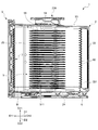
- FIG. 5 is a cross-sectional view showing the substrate storage container 1 according to the embodiment of the present invention.
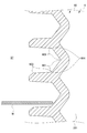
- FIG. 6 is an enlarged cross section showing the positional relationship between the back-side substrate support portion 6 and the substrate W in a state where the container body opening 21 is closed by the lid 3 of the substrate storage container 1 according to the embodiment of the present invention. It is a figure.
- FIG. 7 shows the positional relationship between the back-side substrate support portion 6 and the substrate W when the container body opening 21 is not closed by the lid 3 of the substrate storage container 1 according to the embodiment of the present invention. It is an enlarged sectional view which shows.
- the wall portion 20 of the container main body 2 has a back wall 22, an upper wall 23, a lower wall 24, a first side wall 25, and a second side wall 26.
- the back wall 22, the upper wall 23, the lower wall 24, the first side wall 25, and the second side wall 26 are made of the above-mentioned materials, and are integrally molded.
- the first side wall 25 and the second side wall 26 face each other, and the upper wall 23 and the lower wall 24 face each other.
- the rear end of the upper wall 23, the rear end of the lower wall 24, the rear end of the first side wall 25, and the rear end of the second side wall 26 are all connected to the back wall 22.
- the front end of the upper wall 23, the front end of the lower wall 24, the front end of the first side wall 25, and the front end of the second side wall 26 have a positional relationship facing the back wall 22 and have a substantially rectangular shape of the container body opening 21. Consists of the opening peripheral edge 28 forming the above.
- the opening peripheral edge 28 is provided at one end of the container body 2, and the back wall 22 is located at the other end of the container body 2.
- the outer shape of the container body 2 formed by the outer surface of the wall portion 20 is box-shaped.
- the inner surface of the wall portion 20, that is, the inner surface of the back wall 22, the inner surface of the upper wall 23, the inner surface of the lower wall 24, the inner surface of the first side wall 25, and the inner surface of the second side wall 26 are surrounded by the substrate storage space. 27 is formed.
- the container body opening 21 formed in the opening peripheral edge portion 28 is surrounded by the wall portion 20 and communicates with the substrate storage space 27 formed inside the container body 2. A maximum of 25 boards W can be stored in the board storage space 27.
- the latch engaging recesses 231A and 231B recessed outward of the substrate storage space 27. , 241A and 241B are formed.
- a total of four latch engagement recesses 231A, 231B, 241A, and 241B are formed in the vicinity of the left and right ends of the upper wall 23 and the lower wall 24.
- a rib 235 is provided integrally with the upper wall 23.
- the rib 235 increases the rigidity of the container body 2.
- a top flange 236 is fixed to the central portion of the upper wall 23.
- the top flange 236 is a member that is hung and suspended in the substrate storage container 1 when the substrate storage container 1 is suspended in AMHS (automatic wafer transfer system), PGV (wafer substrate transfer carriage), or the like.
- the board support plate-shaped portion 5 is integrally molded and provided on the first side wall 25 and the second side wall 26, respectively, and is provided in the board storage space 27 so as to form a pair in the left-right direction D3. Specifically, as shown in FIG. 5 and the like, the substrate support plate-shaped portion 5 has a plate portion 51.
- the plate portion 51 has a plate-like substantially arc shape.
- a total of 50 plate portions 51 are provided on each of the first side wall 25 and the second side wall 26, 25 in the vertical direction D2.
- the adjacent plate portions 51 are arranged in a parallel positional relationship so as to be separated from each other at intervals of 10 mm to 12 mm in the vertical direction D2.
- another plate-shaped member 59 is arranged in parallel with the plate portion 51, which is located at the top and is inside the board storage space 27. It is a member that acts as a guide for the substrate W to be inserted into the substrate W.
- the 25 plate portions 51 provided on the first side wall 25 and the 25 plate portions 51 provided on the second side wall 26 have a positional relationship facing each other in the left-right direction D3.
- the 50 plate portions 51 and the member 59 acting as a plate-shaped guide parallel to the plate portions 51 have a positional relationship parallel to the inner surface of the lower wall 24.
- a convex portion 511 is provided on the upper surface of the plate portion 51. The substrate W supported by the plate portion 51 contacts only the protruding end of the convex portion 511 and does not contact the plate portion 51 on the surface.
- the substrate support plate-shaped portion 5 having such a configuration has a plurality of substrates W in a state in which adjacent substrates W among the plurality of substrates W are separated from each other at a predetermined interval and have a parallel positional relationship with each other. It is possible to support the edge of.
- the back side substrate support portion 6 is formed and provided in the rib-shaped portion 221 provided on the back wall 22.
- the rib-shaped portion 221 projects inward of the substrate storage space 27 on the inner surface of the back wall 22.
- the back side board support portion 6 is formed on the inner surface of the rib-shaped portion 221 protruding inward of the board storage space 27, and has a back side edge support portion 60 (see FIG. 5 and the like).
- the number of the back end edge support portions 60 corresponding to each of the boards W that can be stored in the board storage space 27, specifically 25, is provided.
- the rear end edge support portion 60 provided on the back wall 22 has a positional relationship such as pairing with the front retainer 7 described later in the front-rear direction D1.
- the back board support portion 6 has a second contact portion which is a portion having a lower inclined surface 601 as a second contact surface and an upper side as a first contact surface. It has a first contact portion, which is a portion having an inclined surface 602, and a lower contact surface 603.
- the lower inclined surface 601 is composed of an inclined surface that is inclined and extends so as to be separated from the center of the substrate storage space 27 (left side in FIGS. 6 and 7) as it advances in the upward direction D21. ..
- the upper inclined surface 602 is inclined from the upper end portion of the lower inclined surface 601 so as to approach the center of the substrate storage space 27 (left side in FIGS. 6 and 7) as the upper inclined surface 602 proceeds upward D21. It is configured.
- the lower inclined surface 601 and the upper inclined surface 602 form a V-shaped groove 604 which is a concave groove recessed so as to be separated from the center of the substrate storage space 27.
- the edge of the back surface of the substrate W is the lower contact surface. Apart from 603, it slides against the lower inclined surface 601 and, as shown in FIG. 6, the edge of the substrate W is the lower inclined surface 601 and the upper inclined surface at the deepest portion of the V-shaped groove 604. It is supported by being sandwiched between 602 and 602.
- the edge of the back surface of the substrate W is a downward inclined surface. It slides with respect to 601 and abuts on the lower contact surface 603.
- the lid 3 has a substantially rectangular shape that substantially matches the shape of the opening peripheral edge 28 of the container body 2.
- the lid 3 is removable from the opening peripheral edge 28 of the container body 2, and the lid 3 can close the container body opening 21 by attaching the lid 3 to the opening peripheral edge 28. ..
- the inner surface of the lid 3 (the back surface of the lid 3 shown in FIG. 1) at the position of D12 in the immediate rear direction of the opening peripheral edge 28 when the lid 3 closes the container body opening 21.
- An annular seal member 4 is attached to the surface of the formed step portion facing the surface (seal surface 281).
- the seal member 4 is made of various thermoplastic elastomers such as elastically deformable polyester and polyolefin, fluororubber, and silicon rubber. The seal member 4 is arranged so as to go around the outer peripheral edge portion of the lid 3.
- the sealing member 4 When the lid 3 is attached to the opening peripheral edge 28, the sealing member 4 is sandwiched between the sealing surface 281 and the inner surface of the lid 3 and elastically deformed, and the lid 3 seals the container body opening 21. It closes in the state of being closed. By removing the lid 3 from the opening peripheral edge portion 28, the substrate W can be taken in and out of the substrate storage space 27 in the container main body 2.
- the lid 3 is provided with a latch mechanism.
- the latch mechanism is provided in the vicinity of the left and right ends of the lid 3, and as shown in FIG. 1, the two upper latch portions 32A that can project upward from the upper side of the lid 3 to the upward D21, and the lid 3 It includes two lower latch portions 32B that can project downward from the lower side to D22.
- the two upper latch portions 32A are arranged near the left and right ends of the upper side of the lid 3, and the two lower latch portions 32B are arranged near the left and right ends of the lower side of the lid 3.
- An operation unit 33 is provided on the outer surface of the lid 3.
- the upper latch portion 32A and the lower latch portion 32B can be projected from the upper side and the lower side of the lid body 3, and are not projected from the upper side and the lower side. can do.
- the upper latch portion 32A protrudes upward from the upper side of the lid 3 to the upward D21 and engages with the latch engaging recesses 231A and 231B of the container body 2, and the lower latch portion 32B is downward from the lower side of the lid 3.
- the lid 3 is fixed to the opening peripheral edge 28 of the container body 2 by projecting to D22 and engaging with the latch engaging recesses 241A and 241B of the container body 2.
- a recess 34 recessed outward of the substrate storage space 27 is formed inside the lid 3.
- a front retainer 7 is fixedly provided on the portion of the lid 3 inside the recess 34.
- the front retainer 7 has a front retainer board receiving portion 73.
- Two front retainer substrate receiving portions 73 are arranged in pairs in the left-right direction D3 at predetermined intervals.
- the front retainer substrate receiving portions 73 which are arranged in pairs in this way, are provided in a state of 25 pairs in parallel in the vertical direction D2, and are supported by elastically deformable legs. ..
- the front retainer board receiving portion 73 uses the elastic force of the legs to hold the edge of the edge portion of the board W in the board storage space 27. Hold and support it while urging it to the center of the.
- the front retainer substrate receiving portion 73 has a lower inclined surface 731 and an upper inclined surface 732.
- the lower inclined surface 731 comes into contact with the edge of the back surface of the substrate W when the container body opening 21 is closed by the lid 3.
- the upper inclined surface 732 abuts on the edge of the surface of the substrate W.
- the lower inclined surface 731 is composed of an inclined surface that is inclined and extends in the front-rear direction D1 so as to be separated from the center of the substrate storage space 27 as it advances in the upward direction D21.
- the upper inclined surface 732 is composed of an inclined surface that is inclined and extends so as to approach the center of the substrate storage space 27 in the front-rear direction D1 as it advances toward the upward direction D21.
- the lower inclined surface 731 and the upper inclined surface 732 form a V-shaped groove which is a concave groove so as to be separated from the center of the substrate storage space 27.
- the back side substrate support portion 6 and the wall portion 20 constituting the container body 2 integrally molded with the back side substrate support portion 6 are made of an alloy resin mainly composed of a polycarbonate resin and a polybutylene terephthalate resin, and are made of polycarbonate.
- the mass composition of the polybutylene terephthalate resin is larger than the mass of the resin.
- the material of the back substrate support portion 6 and the wall portion 20 contains a polybutylene terephthalate resin having a value larger than 40% by mass with respect to the mass of the alloy resin.
- a polybutylene terephthalate resin having a value larger than 40% by mass with respect to the mass of the alloy resin.
- the back side substrate support portion 6 and the wall portion 20 constituting the container body 2 integrally molded with the back side substrate support portion 6 are made of an alloy resin mainly composed of a polycarbonate resin and a polybutylene terephthalate resin. It is composed and contains a polybutylene terephthalate resin of 51% by mass or more and less than 90% by mass with respect to the mass of the alloy resin. As described above, by setting the polybutylene terephthalate resin to 51% by mass or more with respect to the mass of the alloy resin, the friction coefficient of the substrate W with respect to the lower inclined surface 601 can be made extremely low. Therefore, it is possible to more reliably move the lid W to a predetermined position from which the substrate W is removed.
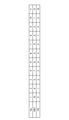
- FIG. 8 shows the polybutylene terephthalate resin (PBT) of the test product 1 (No. 1) to the test product 11 (No. 11) used in the test for testing the effect of the substrate storage container 1 according to the embodiment of the present invention. It is a table which shows the mass ratio with the polycarbonate resin (PC).
- FIG. 9 shows the test products 1 (No. 1) to the test products 11 (No. 11) used in the test for testing the effect of the substrate storage container 1 according to the embodiment of the present invention on the substrate W by the substrate transfer machine. It is a table which shows the result of whether or not it was able to slide to the position which can be taken out automatically.
- FIG. 8 shows the polybutylene terephthalate resin (PBT) of the test product 1 (No. 1) to the test product 11 (No. 11) used in the test for testing the effect of the substrate storage container 1 according to the embodiment of the present invention. It is a table which shows the mass ratio with the polycarbonate resin (PC).
- FIG. 9 shows the
- test product 1 (No. 1) to the test product 11 (No. 11) used in the test for testing the effect of the substrate storage container 1 according to the embodiment of the present invention have a standard range of contamination due to the generation of particles. It is a table showing the result of whether or not it fits inside.
- Test product 2 (No. 2) to test product 5 (No. 5) are the products of the present invention, and are manufactured by changing the mass ratios of the polybutylene terephthalate resin (PBT) and the polycarbonate resin (PC). be.
- the mass ratio of the polybutylene terephthalate resin (PBT) and the polycarbonate resin (PC) is 9: 1.
- the mass ratio of the polybutylene terephthalate resin (PBT) and the polycarbonate resin (PC) is 6: 4.
- Test product 1 (No. 1) and test product 7 (No. 6) to test product 11 (No. 11) are comparative products. Similar to the product of the present invention, for example, for the test product 1 (No. 1), the mass ratio of the polybutylene terephthalate resin (PBT) and the polycarbonate resin (PC) is 10: 0. Similarly, for example, for the test product 11 (No. 11), the mass ratio of the polybutylene terephthalate resin (PBT) and the polycarbonate resin (PC) is 0:10.
- test product 1 to the test product 11 which are the product of the present invention and the comparative product as described above were prepared.
- the test is performed by operating the operation unit 33 of the lid 3 with the substrate transfer machine, removing the lid 3 from the opening peripheral edge 28 of the container body 2, and automatically taking out the substrate by the substrate transfer machine. rice field. The results are as shown in FIGS. 9 and 10.
- the edges of the substrate W were all out of the standard range due to the generation of particles.
- the back substrate support portion 6 and the wall portion 20 are composed of an alloy resin mainly composed of a polycarbonate resin and a polybutylene terephthalate resin, and the mass of the polybutylene terephthalate resin is larger than the mass of the polycarbonate resin.
- the material of the back side substrate support portion 6 and the wall portion 20 is a substrate with respect to the lower inclined surface 601 by containing polybutylene terephthalate resin of 51% by mass or more and less than 90% by mass with respect to the mass of the alloy resin. It can be seen that the friction coefficient of W can be made extremely low, and that contamination due to the generation of particles can be suppressed.
- the back-side substrate support portion 6 of the substrate storage container 1 has a first contact portion having an upper inclined surface 602 as a first contact surface capable of contacting the edge of the surface of the substrate W. It has a second contact surface connected to the upper inclined surface 602 and having a lower inclined surface 601 as a second contact surface capable of contacting the edge of the back surface of the substrate.
- the container body opening 21 is not closed by the lid 3 and the container body opening 21 is closed by the lid 3, the container body opening 21 is closed by the lid 3.
- the substrate W slides with respect to the second contact surface 601 and the back substrate support portion 6 is used.
- It is composed of an alloy resin mainly composed of a polycarbonate resin and a polybutylene terephthalate resin, and the mass of the polybutylene terephthalate resin is larger than the mass of the polycarbonate resin.
- the lid W can be moved, and the substrate W can be automatically taken out by a substrate transfer machine (not shown).
- a substrate storage container that can automatically take out the substrate W by a substrate transfer machine (not shown) and can suppress stains due to the generation of particles during the movement. It will be feasible.
- the material constituting the back substrate support portion 6 contains a polybutylene terephthalate resin having a value larger than 40% by mass with respect to the mass of the alloy resin.
- the back side substrate support portion 6 is composed of an alloy resin mainly composed of a polycarbonate resin and a polybutylene terephthalate resin, and is a polybutylene terephthalate resin having a mass of 51% by mass or more and less than 90% by mass with respect to the mass of the alloy resin. including.
- the substrate storage container 1 is arranged so as to form a pair in the substrate storage space 27, and when the container main body opening 21 is not closed by the lid 3, the adjacent substrate W among the plurality of substrates W
- a substrate support plate-shaped portion 5 as a side substrate support portion capable of supporting the edges of a plurality of substrates W is provided in a state where the substrates W are separated from each other at a predetermined interval and arranged in parallel, and the back side substrate support portion 6 is provided.
- the edges of the plurality of boards W are separated from the board support plate-shaped portion 5 in cooperation with the front retainer 7 as the board support portion on the lid side. Supports a plurality of substrates W in a parallel state.
- the edge of the board W is the second hit. Although it slides with respect to the contact surface 601, it is possible to more reliably take out the substrate W by a substrate transfer machine (not shown) to facilitate this sliding, and particles are generated during the movement. It is also possible to realize a substrate storage container 1 that can be more reliably suppressed from being contaminated due to the generation of particles.
- the edge of the substrate W is formed by the lower inclined surface 601 as the first contact surface and the upper inclined surface 602 as the second contact surface.
- the substrate W is supported so as to sandwich the substrate W.
- the lower inclined surface 601 and the upper inclined surface 602 sandwich the edge of the substrate W, and the lid 3 does not block the container body opening 21.
- the edge of the substrate W is not sandwiched between the 601 and the upper inclined surface 602, the edge of the substrate W can be reliably slid with respect to the lower inclined surface 601. It is possible to move W to a predetermined position from which the substrate W is removed more reliably.
- the container body opening 21 when the container body opening 21 is not closed by the lid 3, the container body opening 21 is closed by the lid 3, and the container is closed by the lid 3.
- the substrate W with respect to the second contact surface 601 both when the main body opening 21 is closed and when the container main body opening 21 is not closed by the lid 3. Sliding, but not limited to this. That is, when the container body opening 21 is not closed by the lid 3 and the container body opening 21 is closed by the lid 3, the container body opening 21 is closed by the lid 3.
- the substrate W may slide with respect to the second contact surface 601 when the container body opening 21 is not closed by the lid 3 and at least one of the cases. ..
- the shapes of the container body and the lid, the number and dimensions of the substrates W that can be stored in the container body are determined by the shapes of the container body 2 and the lid 3 in the present embodiment, and the substrate W that can be stored in the container body 2. It is not limited to the number of sheets or dimensions. That is, the configuration of the side substrate support portion, the lid side substrate support portion, and the back side substrate support portion is not limited to the configuration of the substrate support plate-shaped portion 5, the front retainer 7, and the back side substrate support portion 6. Further, the substrate W in the present embodiment is a silicon wafer having a diameter of 300 mm, but the value is not limited to this.
Landscapes
- Engineering & Computer Science (AREA)
- Mechanical Engineering (AREA)
- Packaging Frangible Articles (AREA)
- Container, Conveyance, Adherence, Positioning, Of Wafer (AREA)
- Robotics (AREA)
Priority Applications (4)
| Application Number | Priority Date | Filing Date | Title |
|---|---|---|---|
| US17/999,368 US12431377B2 (en) | 2020-05-19 | 2020-05-19 | Substrate storage container |
| JP2022523786A JP7562657B2 (ja) | 2020-05-19 | 2020-05-19 | 基板収納容器 |
| PCT/JP2020/019740 WO2021234809A1 (ja) | 2020-05-19 | 2020-05-19 | 基板収納容器 |
| TW110117756A TWI883193B (zh) | 2020-05-19 | 2021-05-17 | 基板收納容器 |
Applications Claiming Priority (1)
| Application Number | Priority Date | Filing Date | Title |
|---|---|---|---|
| PCT/JP2020/019740 WO2021234809A1 (ja) | 2020-05-19 | 2020-05-19 | 基板収納容器 |
Publications (1)
| Publication Number | Publication Date |
|---|---|
| WO2021234809A1 true WO2021234809A1 (ja) | 2021-11-25 |
Family
ID=78708560
Family Applications (1)
| Application Number | Title | Priority Date | Filing Date |
|---|---|---|---|
| PCT/JP2020/019740 Ceased WO2021234809A1 (ja) | 2020-05-19 | 2020-05-19 | 基板収納容器 |
Country Status (4)
| Country | Link |
|---|---|
| US (1) | US12431377B2 (https=) |
| JP (1) | JP7562657B2 (https=) |
| TW (1) | TWI883193B (https=) |
| WO (1) | WO2021234809A1 (https=) |
Families Citing this family (4)
| Publication number | Priority date | Publication date | Assignee | Title |
|---|---|---|---|---|
| USD1067892S1 (en) * | 2021-09-06 | 2025-03-25 | Gudeng Precision Industrial Co., Ltd. | Box for transporting boards |
| TWD223990S (zh) * | 2022-03-03 | 2023-03-01 | 家登精密工業股份有限公司 | 前開式晶圓載具 |
| TWI848670B (zh) * | 2022-06-30 | 2024-07-11 | 家登精密工業股份有限公司 | 保護包裝組件 |
| US20240412994A1 (en) * | 2023-06-06 | 2024-12-12 | Entegris, Inc. | Substrate container, and door locking mechanism thereof |
Citations (2)
| Publication number | Priority date | Publication date | Assignee | Title |
|---|---|---|---|---|
| JPH11115985A (ja) * | 1997-10-14 | 1999-04-27 | Kakizaki Seisakusho:Kk | 帯電防止型薄板収納容器 |
| JP2016048757A (ja) * | 2014-08-28 | 2016-04-07 | ミライアル株式会社 | 基板収納容器 |
Family Cites Families (5)
| Publication number | Priority date | Publication date | Assignee | Title |
|---|---|---|---|---|
| JP2011018771A (ja) * | 2009-07-09 | 2011-01-27 | Shin Etsu Polymer Co Ltd | 基板収納容器 |
| JP6114193B2 (ja) * | 2010-10-20 | 2017-04-12 | インテグリス・インコーポレーテッド | ドア・ガイドおよびシールを備えたウェーハ容器 |
| WO2013069088A1 (ja) * | 2011-11-08 | 2013-05-16 | ミライアル株式会社 | ウェーハ収納容器 |
| SG11201707411QA (en) | 2015-04-10 | 2017-10-30 | Shinetsu Polymer Co | Substrate storage container |
| US11309200B2 (en) | 2017-02-27 | 2022-04-19 | Miraial Co., Ltd. | Substrate storage container |
-
2020
- 2020-05-19 JP JP2022523786A patent/JP7562657B2/ja active Active
- 2020-05-19 WO PCT/JP2020/019740 patent/WO2021234809A1/ja not_active Ceased
- 2020-05-19 US US17/999,368 patent/US12431377B2/en active Active
-
2021
- 2021-05-17 TW TW110117756A patent/TWI883193B/zh active
Patent Citations (2)
| Publication number | Priority date | Publication date | Assignee | Title |
|---|---|---|---|---|
| JPH11115985A (ja) * | 1997-10-14 | 1999-04-27 | Kakizaki Seisakusho:Kk | 帯電防止型薄板収納容器 |
| JP2016048757A (ja) * | 2014-08-28 | 2016-04-07 | ミライアル株式会社 | 基板収納容器 |
Also Published As
| Publication number | Publication date |
|---|---|
| US20230238265A1 (en) | 2023-07-27 |
| TW202144266A (zh) | 2021-12-01 |
| TWI883193B (zh) | 2025-05-11 |
| JP7562657B2 (ja) | 2024-10-07 |
| US12431377B2 (en) | 2025-09-30 |
| JPWO2021234809A1 (https=) | 2021-11-25 |
Similar Documents
| Publication | Publication Date | Title |
|---|---|---|
| WO2021234809A1 (ja) | 基板収納容器 | |
| JP6915037B2 (ja) | 基板収納容器 | |
| JP7414982B2 (ja) | 基板収納容器 | |
| JP6854341B2 (ja) | 基板収納容器 | |
| JPWO2019239495A1 (ja) | 基板収納容器 | |
| TWI796660B (zh) | 基板收納容器 | |
| TWI816950B (zh) | 基板收納容器 | |
| WO2022208602A1 (ja) | 基板収納容器 | |
| JP2016149492A (ja) | 基板収納容器 | |
| JP2016119408A (ja) | 基板収納容器 | |
| TW202032700A (zh) | 基板收納容器 | |
| TW201529455A (zh) | 基板收納容器 | |
| WO2018179324A1 (ja) | 基板収納容器 | |
| TW202539966A (zh) | 基板收納容器 | |
| WO2023026485A1 (ja) | 基板収納容器、その製造方法、及び蓋体側基板支持部 | |
| JP2007142192A (ja) | 薄板体収納容器 | |
| JPWO2019030863A1 (ja) | 基板収納容器 | |
| WO2024105879A1 (ja) | 収納容器及びアダプター部材 | |
| WO2023017591A1 (ja) | 基板収納容器 | |
| WO2018154778A1 (ja) | 基板収納容器 |
Legal Events
| Date | Code | Title | Description |
|---|---|---|---|
| 121 | Ep: the epo has been informed by wipo that ep was designated in this application |
Ref document number: 20937000 Country of ref document: EP Kind code of ref document: A1 |
|
| DPE1 | Request for preliminary examination filed after expiration of 19th month from priority date (pct application filed from 20040101) | ||
| ENP | Entry into the national phase |
Ref document number: 2022523786 Country of ref document: JP Kind code of ref document: A |
|
| NENP | Non-entry into the national phase |
Ref country code: DE |
|
| 122 | Ep: pct application non-entry in european phase |
Ref document number: 20937000 Country of ref document: EP Kind code of ref document: A1 |
|
| WWG | Wipo information: grant in national office |
Ref document number: 17999368 Country of ref document: US |