WO2021234809A1 - 基板収納容器 - Google Patents
基板収納容器 Download PDFInfo
- Publication number
- WO2021234809A1 WO2021234809A1 PCT/JP2020/019740 JP2020019740W WO2021234809A1 WO 2021234809 A1 WO2021234809 A1 WO 2021234809A1 JP 2020019740 W JP2020019740 W JP 2020019740W WO 2021234809 A1 WO2021234809 A1 WO 2021234809A1
- Authority
- WO
- WIPO (PCT)
- Prior art keywords
- lid
- substrate
- container body
- closed
- support portion
- Prior art date
Links
Images


Classifications
-
- H—ELECTRICITY
- H01—ELECTRIC ELEMENTS
- H01L—SEMICONDUCTOR DEVICES NOT COVERED BY CLASS H10
- H01L21/00—Processes or apparatus adapted for the manufacture or treatment of semiconductor or solid state devices or of parts thereof
- H01L21/67—Apparatus specially adapted for handling semiconductor or electric solid state devices during manufacture or treatment thereof; Apparatus specially adapted for handling wafers during manufacture or treatment of semiconductor or electric solid state devices or components ; Apparatus not specifically provided for elsewhere
- H01L21/677—Apparatus specially adapted for handling semiconductor or electric solid state devices during manufacture or treatment thereof; Apparatus specially adapted for handling wafers during manufacture or treatment of semiconductor or electric solid state devices or components ; Apparatus not specifically provided for elsewhere for conveying, e.g. between different workstations
- H01L21/67763—Apparatus specially adapted for handling semiconductor or electric solid state devices during manufacture or treatment thereof; Apparatus specially adapted for handling wafers during manufacture or treatment of semiconductor or electric solid state devices or components ; Apparatus not specifically provided for elsewhere for conveying, e.g. between different workstations the wafers being stored in a carrier, involving loading and unloading
- H01L21/67769—Storage means
-
- B—PERFORMING OPERATIONS; TRANSPORTING
- B65—CONVEYING; PACKING; STORING; HANDLING THIN OR FILAMENTARY MATERIAL
- B65D—CONTAINERS FOR STORAGE OR TRANSPORT OF ARTICLES OR MATERIALS, e.g. BAGS, BARRELS, BOTTLES, BOXES, CANS, CARTONS, CRATES, DRUMS, JARS, TANKS, HOPPERS, FORWARDING CONTAINERS; ACCESSORIES, CLOSURES, OR FITTINGS THEREFOR; PACKAGING ELEMENTS; PACKAGES
- B65D85/00—Containers, packaging elements or packages, specially adapted for particular articles or materials
- B65D85/30—Containers, packaging elements or packages, specially adapted for particular articles or materials for articles particularly sensitive to damage by shock or pressure
-
- H—ELECTRICITY
- H01—ELECTRIC ELEMENTS
- H01L—SEMICONDUCTOR DEVICES NOT COVERED BY CLASS H10
- H01L21/00—Processes or apparatus adapted for the manufacture or treatment of semiconductor or solid state devices or of parts thereof
- H01L21/67—Apparatus specially adapted for handling semiconductor or electric solid state devices during manufacture or treatment thereof; Apparatus specially adapted for handling wafers during manufacture or treatment of semiconductor or electric solid state devices or components ; Apparatus not specifically provided for elsewhere
- H01L21/673—Apparatus specially adapted for handling semiconductor or electric solid state devices during manufacture or treatment thereof; Apparatus specially adapted for handling wafers during manufacture or treatment of semiconductor or electric solid state devices or components ; Apparatus not specifically provided for elsewhere using specially adapted carriers or holders; Fixing the workpieces on such carriers or holders
- H01L21/6735—Closed carriers
- H01L21/67369—Closed carriers characterised by shock absorbing elements, e.g. retainers or cushions
-
- H—ELECTRICITY
- H01—ELECTRIC ELEMENTS
- H01L—SEMICONDUCTOR DEVICES NOT COVERED BY CLASS H10
- H01L21/00—Processes or apparatus adapted for the manufacture or treatment of semiconductor or solid state devices or of parts thereof
- H01L21/67—Apparatus specially adapted for handling semiconductor or electric solid state devices during manufacture or treatment thereof; Apparatus specially adapted for handling wafers during manufacture or treatment of semiconductor or electric solid state devices or components ; Apparatus not specifically provided for elsewhere
- H01L21/673—Apparatus specially adapted for handling semiconductor or electric solid state devices during manufacture or treatment thereof; Apparatus specially adapted for handling wafers during manufacture or treatment of semiconductor or electric solid state devices or components ; Apparatus not specifically provided for elsewhere using specially adapted carriers or holders; Fixing the workpieces on such carriers or holders
- H01L21/6735—Closed carriers
- H01L21/67373—Closed carriers characterised by locking systems
-
- H—ELECTRICITY
- H01—ELECTRIC ELEMENTS
- H01L—SEMICONDUCTOR DEVICES NOT COVERED BY CLASS H10
- H01L21/00—Processes or apparatus adapted for the manufacture or treatment of semiconductor or solid state devices or of parts thereof
- H01L21/67—Apparatus specially adapted for handling semiconductor or electric solid state devices during manufacture or treatment thereof; Apparatus specially adapted for handling wafers during manufacture or treatment of semiconductor or electric solid state devices or components ; Apparatus not specifically provided for elsewhere
- H01L21/673—Apparatus specially adapted for handling semiconductor or electric solid state devices during manufacture or treatment thereof; Apparatus specially adapted for handling wafers during manufacture or treatment of semiconductor or electric solid state devices or components ; Apparatus not specifically provided for elsewhere using specially adapted carriers or holders; Fixing the workpieces on such carriers or holders
- H01L21/6735—Closed carriers
- H01L21/67379—Closed carriers characterised by coupling elements, kinematic members, handles or elements to be externally gripped
-
- H—ELECTRICITY
- H01—ELECTRIC ELEMENTS
- H01L—SEMICONDUCTOR DEVICES NOT COVERED BY CLASS H10
- H01L21/00—Processes or apparatus adapted for the manufacture or treatment of semiconductor or solid state devices or of parts thereof
- H01L21/67—Apparatus specially adapted for handling semiconductor or electric solid state devices during manufacture or treatment thereof; Apparatus specially adapted for handling wafers during manufacture or treatment of semiconductor or electric solid state devices or components ; Apparatus not specifically provided for elsewhere
- H01L21/673—Apparatus specially adapted for handling semiconductor or electric solid state devices during manufacture or treatment thereof; Apparatus specially adapted for handling wafers during manufacture or treatment of semiconductor or electric solid state devices or components ; Apparatus not specifically provided for elsewhere using specially adapted carriers or holders; Fixing the workpieces on such carriers or holders
- H01L21/6735—Closed carriers
- H01L21/67383—Closed carriers characterised by substrate supports
-
- H—ELECTRICITY
- H01—ELECTRIC ELEMENTS
- H01L—SEMICONDUCTOR DEVICES NOT COVERED BY CLASS H10
- H01L21/00—Processes or apparatus adapted for the manufacture or treatment of semiconductor or solid state devices or of parts thereof
- H01L21/67—Apparatus specially adapted for handling semiconductor or electric solid state devices during manufacture or treatment thereof; Apparatus specially adapted for handling wafers during manufacture or treatment of semiconductor or electric solid state devices or components ; Apparatus not specifically provided for elsewhere
- H01L21/673—Apparatus specially adapted for handling semiconductor or electric solid state devices during manufacture or treatment thereof; Apparatus specially adapted for handling wafers during manufacture or treatment of semiconductor or electric solid state devices or components ; Apparatus not specifically provided for elsewhere using specially adapted carriers or holders; Fixing the workpieces on such carriers or holders
- H01L21/6735—Closed carriers
- H01L21/67386—Closed carriers characterised by the construction of the closed carrier
-
- H—ELECTRICITY
- H01—ELECTRIC ELEMENTS
- H01L—SEMICONDUCTOR DEVICES NOT COVERED BY CLASS H10
- H01L21/00—Processes or apparatus adapted for the manufacture or treatment of semiconductor or solid state devices or of parts thereof
- H01L21/67—Apparatus specially adapted for handling semiconductor or electric solid state devices during manufacture or treatment thereof; Apparatus specially adapted for handling wafers during manufacture or treatment of semiconductor or electric solid state devices or components ; Apparatus not specifically provided for elsewhere
- H01L21/677—Apparatus specially adapted for handling semiconductor or electric solid state devices during manufacture or treatment thereof; Apparatus specially adapted for handling wafers during manufacture or treatment of semiconductor or electric solid state devices or components ; Apparatus not specifically provided for elsewhere for conveying, e.g. between different workstations
- H01L21/67739—Apparatus specially adapted for handling semiconductor or electric solid state devices during manufacture or treatment thereof; Apparatus specially adapted for handling wafers during manufacture or treatment of semiconductor or electric solid state devices or components ; Apparatus not specifically provided for elsewhere for conveying, e.g. between different workstations into and out of processing chamber
- H01L21/67742—Mechanical parts of transfer devices
-
- H—ELECTRICITY
- H01—ELECTRIC ELEMENTS
- H01L—SEMICONDUCTOR DEVICES NOT COVERED BY CLASS H10
- H01L21/00—Processes or apparatus adapted for the manufacture or treatment of semiconductor or solid state devices or of parts thereof
- H01L21/67—Apparatus specially adapted for handling semiconductor or electric solid state devices during manufacture or treatment thereof; Apparatus specially adapted for handling wafers during manufacture or treatment of semiconductor or electric solid state devices or components ; Apparatus not specifically provided for elsewhere
- H01L21/677—Apparatus specially adapted for handling semiconductor or electric solid state devices during manufacture or treatment thereof; Apparatus specially adapted for handling wafers during manufacture or treatment of semiconductor or electric solid state devices or components ; Apparatus not specifically provided for elsewhere for conveying, e.g. between different workstations
- H01L21/67763—Apparatus specially adapted for handling semiconductor or electric solid state devices during manufacture or treatment thereof; Apparatus specially adapted for handling wafers during manufacture or treatment of semiconductor or electric solid state devices or components ; Apparatus not specifically provided for elsewhere for conveying, e.g. between different workstations the wafers being stored in a carrier, involving loading and unloading
- H01L21/67766—Mechanical parts of transfer devices
Definitions
- the present invention relates to a substrate storage container used for storing, storing, transporting, transporting, etc. a substrate made of a semiconductor wafer or the like.
- Patent Document 1 As a substrate storage container for storing and transporting a substrate made of a semiconductor wafer, a container having a container body and a wafer carrier has been conventionally known (see, for example, Patent Document 1).
- One end of the container body has an opening peripheral portion on which the container body opening is formed.
- the other end of the container body has a closed tubular wall.
- a substrate storage space is formed in the container body.
- the board storage space is formed by being surrounded by a wall portion, and can store a plurality of boards.
- the lid is removable from the peripheral edge of the opening and can close the opening of the container body.
- the side substrate support portions are provided on the wall portion so as to form a pair in the substrate storage space.
- the side substrate support can support the edges of a plurality of substrates in a state where adjacent substrates are separated from each other at predetermined intervals and arranged in parallel when the opening of the container body is not closed by the lid. be.
- a front retainer is provided in the part of the lid that faces the board storage space when the opening of the container body is closed.
- the front retainer has a lid-side substrate receiving portion that directly contacts the substrate and supports the substrate, and a lid-side leg that supports the lid-side substrate receiving portion, and the container body opening is closed by the lid. It is possible to support the edges of multiple substrates when
- a back board support portion is provided on the wall portion so as to be paired with the front retainer.
- the back board support portion can support the edges of a plurality of boards.
- the back-side substrate support portion supports a plurality of substrates in cooperation with the front retainer to separate adjacent substrates at predetermined intervals. Hold multiple boards in parallel.
- the back board support portion cooperates with the front retainer to sandwich a plurality of boards in order to suppress damage and rotation of the board.
- a plurality of substrates are held and fixed in a state where adjacent substrates are separated from each other at a predetermined interval and arranged in parallel.
- the coefficient of friction of the material that constitutes the back board support is low, even if the board is held with a strong force, the board will rotate due to vibration during transportation of the board storage container, and stains due to the generation of particles will occur. Is easy to generate. Further, when the friction coefficient of the material constituting the back side substrate support portion is high, even if the substrate is held with a light force, the substrate is difficult to rotate due to vibration during transportation and the like, and there is little dirt due to the generation of particles.
- the container body opening is not closed by the lid from the container body opening is not closed by the lid.
- the edge of the substrate is with respect to the back side substrate support portion. Therefore, there is a problem that the substrate cannot be slid smoothly, the substrate cannot be moved to a predetermined position where the substrate is removed, and the substrate cannot be automatically taken out by the substrate transfer machine.
- the present invention provides a substrate storage container that can be reliably moved to a predetermined position from which the substrate is removed, that the substrate can be automatically taken out by a substrate transfer machine, and that is less contaminated by the generation of particles. With the goal.
- the present invention has an opening peripheral portion in which an opening of a container body is formed at one end, and has a tubular wall portion in which the other end is closed, and a plurality of substrates can be stored by the inner surface of the wall portion.
- a container body having a substrate storage space communicating with the container body opening, a lid that can be attached to and detached from the container body opening, and a lid that can close the container body opening, and the lid.
- the lid-side substrate support portion capable of supporting the edges of the plurality of substrates is arranged so as to be paired with the lid-side substrate support portion in the substrate storage space, and the edge portions of the plurality of substrates can be supported.
- the back side that supports the plurality of substrates in a state of cooperating with the lid side substrate support portion and arranging the plurality of substrates in parallel.
- a substrate support portion is provided, and the back-side substrate support portion is connected to a first contact portion having a first contact surface capable of contacting an edge of the surface of the substrate and the first contact surface.
- the present invention relates to a substrate storage container which is composed of an alloy resin mainly composed of a resin and has a mass composition in which the mass of a polybutylene terephthalate resin is larger than the mass of a polycarbonate resin.
- the material constituting the back side substrate support portion contains polybutylene terephthalate resin in an amount of 51% by mass or more with respect to the mass of the alloy resin.
- the back side substrate support portion is composed of an alloy resin mainly composed of a polycarbonate resin and a polybutylene terephthalate resin, and a polybutylene terephthalate resin having a mass of 51% by mass or more and less than 90% by mass with respect to the mass of the alloy resin is used. It is preferable to include it.
- the back side substrate support portion is provided with a side substrate support portion capable of supporting the edges of the plurality of substrates in a parallel state. It is preferable to support the plurality of substrates in a state in which the edges of the plurality of substrates are separated from the side substrate support portions and arranged in parallel in cooperation with the lid side substrate support portion.
- the substrate when the opening of the container body is closed by the lid, it is preferable to support the substrate so that the edge of the substrate is sandwiched between the first contact surface and the second contact surface. ..
- the present invention it is possible to provide a substrate storage container that can be reliably moved to a predetermined position from which the substrate is removed and that the substrate can be automatically taken out by a substrate transfer machine.
- FIG. 5 is an exploded perspective view showing a state in which a plurality of substrates W are stored in the substrate storage container 1 according to the embodiment of the present invention. It is a perspective view which shows the container main body 2 of the substrate storage container 1 which concerns on embodiment of this invention.
- FIG. 5 is an exploded perspective view showing a state in which one substrate W is stored in the container body 2 of the substrate storage container 1 according to the embodiment of the present invention. It is a perspective view which shows the cover body 3 of the substrate storage container 1 which concerns on embodiment of this invention. It is sectional drawing which shows the substrate storage container 1 which concerns on embodiment of this invention.
- FIG. 5 is an exploded perspective view showing a state in which a plurality of substrates W are stored in the substrate storage container 1 according to the embodiment of the present invention. It is a perspective view which shows the container main body 2 of the substrate storage container 1 which concerns on embodiment of this invention.
- FIG. 5 is an exploded perspective view showing a state in which one substrate W is stored in the container body 2 of the substrate
- FIG. 5 is an enlarged cross-sectional view showing a positional relationship between a back-side substrate support portion 6 and a substrate W in a state where the container body opening 21 is closed by the lid 3 of the substrate storage container 1 according to the embodiment of the present invention.
- PBT Polybutylene terephthalate resin
- PC polycarbonate resin
- the substrate W is automatically taken out by the substrate transfer machine. It is a table which shows the result of whether or not it was able to slide to a position where it is possible.
- the stains due to the generation of particles are within the standard range. It is a table showing the result of whether or not.
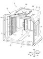
- FIG. 1 is an exploded perspective view showing a state in which a plurality of substrates W are stored in the substrate storage container 1 according to the embodiment of the present invention.
- FIG. 2 is a perspective view showing a container body 2 of the substrate storage container 1 according to the embodiment of the present invention.
- FIG. 3 is an exploded perspective view showing a state in which one substrate W is stored in the container body 2 of the substrate storage container 1 according to the embodiment of the present invention.
- FIG. 4 is a perspective view showing a lid 3 of the substrate storage container 1 according to the embodiment of the present invention.
- the direction from the container body 2 to the lid 3 (the direction from the upper right to the lower left in FIG. 1) is defined as the front direction D11, and the opposite direction is defined as the rear direction D12. These are collectively defined as the front-back direction D1.
- the direction from the lower wall 24 to the upper wall 23 (upward in FIG. 1), which will be described later, is defined as the upward direction D21, and the opposite direction is defined as the downward direction D22, which are collectively referred to as the vertical direction D2.
- the direction from the second side wall 26 to the first side wall 25 (the direction from the lower right to the upper left in FIG. 1), which will be described later, is defined as the left direction D31, and the opposite direction is defined as the right direction D32. Is also defined as the left-right direction D3.
- the main drawings show arrows pointing in these directions.
- the substrate W (see FIG. 1) stored in the substrate storage container 1 is a disk-shaped silicon wafer, a glass wafer, a sapphire wafer, or the like, and is a thin one used in industry.
- the substrate W in this embodiment is a silicon wafer having a diameter of 300 mm.
- the substrate storage container 1 is a shipping container for accommodating a substrate W made of a silicon wafer as described above and transporting the substrate W by transportation means such as land transportation means, air transportation means, and shipping means. It is used as a container body 2 and a lid body 3.
- the container body 2 includes a substrate support plate-shaped portion 5 as a side substrate support portion and a back side substrate support portion 6 (see FIG. 2 and the like), and the lid 3 serves as a lid side substrate support portion. It is equipped with a front retainer 7 (see FIG. 4, etc.).
- the container body 2 has a cylindrical wall portion 20 having a container body opening 21 formed at one end and a closed end.
- a substrate storage space 27 is formed in the container body 2.
- the board storage space 27 is formed by being surrounded by the wall portion 20.
- a substrate support plate-shaped portion 5 is arranged in a portion of the wall portion 20 that forms the substrate storage space 27. As shown in FIG. 1, a plurality of boards W can be stored in the board storage space 27.
- the board support plate-shaped portion 5 is provided on the wall portion 20 so as to form a pair in the board storage space 27.
- the substrate support plate-shaped portion 5 abuts on the edges of a plurality of substrates W to separate adjacent substrates W from each other at predetermined intervals. It is possible to support the edges of a plurality of substrates W in a parallel state.
- a back side board support portion 6 is provided on the back side of the board support plate-shaped portion 5.
- the back side board support portion 6 is provided on the wall portion 20 so as to be paired with the front retainer 7 described later in the board storage space 27.
- the back-side substrate support portion 6 can support the rear portions of the edges of the plurality of substrates W by abutting against the edges of the plurality of substrates W. Is.
- the lid 3 is removable from the opening peripheral edge 28 (FIG. 1 and the like) forming the container body opening 21, and the container body opening 21 can be closed.
- the front retainer 7 is provided in a portion of the lid 3 that faces the substrate storage space 27 when the container body opening 21 is closed by the lid 3.
- the front retainer 7 is arranged so as to be paired with the back side board support portion 6 inside the board storage space 27.
- the front retainer 7 can support the front portion of the edge portion of the plurality of substrates W by abutting on the edge portion of the plurality of substrates W when the container body opening 21 is closed by the lid body 3.
- the front retainer 7 supports a plurality of substrates W in cooperation with the back-side substrate support portion 6, thereby designating adjacent substrates W to each other.
- a plurality of substrates W are held in a state of being spaced apart from each other and arranged in parallel.
- the substrate storage container 1 is made of a resin such as a plastic material, and unless otherwise specified, the resin of the material may be, for example, polycarbonate, cycloolefin polymer, polyetherimide, polyetherketone, or polybutylene.
- Thermoplastic resins such as terephthalate, polyetheretherketone, and liquid crystal polymers, and their alloys can be mentioned.
- a conductive substance such as carbon fiber, carbon powder, carbon nanotubes, or a conductive polymer is selectively added to the resin of these molding materials. It is also possible to add glass fiber, carbon fiber or the like in order to increase the rigidity.
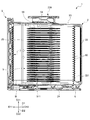
- FIG. 5 is a cross-sectional view showing the substrate storage container 1 according to the embodiment of the present invention.
- FIG. 6 is an enlarged cross section showing the positional relationship between the back-side substrate support portion 6 and the substrate W in a state where the container body opening 21 is closed by the lid 3 of the substrate storage container 1 according to the embodiment of the present invention. It is a figure.
- FIG. 7 shows the positional relationship between the back-side substrate support portion 6 and the substrate W when the container body opening 21 is not closed by the lid 3 of the substrate storage container 1 according to the embodiment of the present invention. It is an enlarged sectional view which shows.
- the wall portion 20 of the container main body 2 has a back wall 22, an upper wall 23, a lower wall 24, a first side wall 25, and a second side wall 26.
- the back wall 22, the upper wall 23, the lower wall 24, the first side wall 25, and the second side wall 26 are made of the above-mentioned materials, and are integrally molded.
- the first side wall 25 and the second side wall 26 face each other, and the upper wall 23 and the lower wall 24 face each other.
- the rear end of the upper wall 23, the rear end of the lower wall 24, the rear end of the first side wall 25, and the rear end of the second side wall 26 are all connected to the back wall 22.
- the front end of the upper wall 23, the front end of the lower wall 24, the front end of the first side wall 25, and the front end of the second side wall 26 have a positional relationship facing the back wall 22 and have a substantially rectangular shape of the container body opening 21. Consists of the opening peripheral edge 28 forming the above.
- the opening peripheral edge 28 is provided at one end of the container body 2, and the back wall 22 is located at the other end of the container body 2.
- the outer shape of the container body 2 formed by the outer surface of the wall portion 20 is box-shaped.
- the inner surface of the wall portion 20, that is, the inner surface of the back wall 22, the inner surface of the upper wall 23, the inner surface of the lower wall 24, the inner surface of the first side wall 25, and the inner surface of the second side wall 26 are surrounded by the substrate storage space. 27 is formed.
- the container body opening 21 formed in the opening peripheral edge portion 28 is surrounded by the wall portion 20 and communicates with the substrate storage space 27 formed inside the container body 2. A maximum of 25 boards W can be stored in the board storage space 27.
- the latch engaging recesses 231A and 231B recessed outward of the substrate storage space 27. , 241A and 241B are formed.
- a total of four latch engagement recesses 231A, 231B, 241A, and 241B are formed in the vicinity of the left and right ends of the upper wall 23 and the lower wall 24.
- a rib 235 is provided integrally with the upper wall 23.
- the rib 235 increases the rigidity of the container body 2.
- a top flange 236 is fixed to the central portion of the upper wall 23.
- the top flange 236 is a member that is hung and suspended in the substrate storage container 1 when the substrate storage container 1 is suspended in AMHS (automatic wafer transfer system), PGV (wafer substrate transfer carriage), or the like.
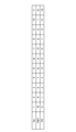
- the board support plate-shaped portion 5 is integrally molded and provided on the first side wall 25 and the second side wall 26, respectively, and is provided in the board storage space 27 so as to form a pair in the left-right direction D3. Specifically, as shown in FIG. 5 and the like, the substrate support plate-shaped portion 5 has a plate portion 51.
- the plate portion 51 has a plate-like substantially arc shape.
- a total of 50 plate portions 51 are provided on each of the first side wall 25 and the second side wall 26, 25 in the vertical direction D2.
- the adjacent plate portions 51 are arranged in a parallel positional relationship so as to be separated from each other at intervals of 10 mm to 12 mm in the vertical direction D2.
- another plate-shaped member 59 is arranged in parallel with the plate portion 51, which is located at the top and is inside the board storage space 27. It is a member that acts as a guide for the substrate W to be inserted into the substrate W.
- the 25 plate portions 51 provided on the first side wall 25 and the 25 plate portions 51 provided on the second side wall 26 have a positional relationship facing each other in the left-right direction D3.
- the 50 plate portions 51 and the member 59 acting as a plate-shaped guide parallel to the plate portions 51 have a positional relationship parallel to the inner surface of the lower wall 24.
- a convex portion 511 is provided on the upper surface of the plate portion 51. The substrate W supported by the plate portion 51 contacts only the protruding end of the convex portion 511 and does not contact the plate portion 51 on the surface.
- the substrate support plate-shaped portion 5 having such a configuration has a plurality of substrates W in a state in which adjacent substrates W among the plurality of substrates W are separated from each other at a predetermined interval and have a parallel positional relationship with each other. It is possible to support the edge of.
- the back side substrate support portion 6 is formed and provided in the rib-shaped portion 221 provided on the back wall 22.
- the rib-shaped portion 221 projects inward of the substrate storage space 27 on the inner surface of the back wall 22.
- the back side board support portion 6 is formed on the inner surface of the rib-shaped portion 221 protruding inward of the board storage space 27, and has a back side edge support portion 60 (see FIG. 5 and the like).
- the number of the back end edge support portions 60 corresponding to each of the boards W that can be stored in the board storage space 27, specifically 25, is provided.
- the rear end edge support portion 60 provided on the back wall 22 has a positional relationship such as pairing with the front retainer 7 described later in the front-rear direction D1.
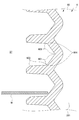
- the back board support portion 6 has a second contact portion which is a portion having a lower inclined surface 601 as a second contact surface and an upper side as a first contact surface. It has a first contact portion, which is a portion having an inclined surface 602, and a lower contact surface 603.
- the lower inclined surface 601 is composed of an inclined surface that is inclined and extends so as to be separated from the center of the substrate storage space 27 (left side in FIGS. 6 and 7) as it advances in the upward direction D21. ..
- the upper inclined surface 602 is inclined from the upper end portion of the lower inclined surface 601 so as to approach the center of the substrate storage space 27 (left side in FIGS. 6 and 7) as the upper inclined surface 602 proceeds upward D21. It is configured.
- the lower inclined surface 601 and the upper inclined surface 602 form a V-shaped groove 604 which is a concave groove recessed so as to be separated from the center of the substrate storage space 27.
- the edge of the back surface of the substrate W is the lower contact surface. Apart from 603, it slides against the lower inclined surface 601 and, as shown in FIG. 6, the edge of the substrate W is the lower inclined surface 601 and the upper inclined surface at the deepest portion of the V-shaped groove 604. It is supported by being sandwiched between 602 and 602.
- the edge of the back surface of the substrate W is a downward inclined surface. It slides with respect to 601 and abuts on the lower contact surface 603.
- the lid 3 has a substantially rectangular shape that substantially matches the shape of the opening peripheral edge 28 of the container body 2.
- the lid 3 is removable from the opening peripheral edge 28 of the container body 2, and the lid 3 can close the container body opening 21 by attaching the lid 3 to the opening peripheral edge 28. ..
- the inner surface of the lid 3 (the back surface of the lid 3 shown in FIG. 1) at the position of D12 in the immediate rear direction of the opening peripheral edge 28 when the lid 3 closes the container body opening 21.
- An annular seal member 4 is attached to the surface of the formed step portion facing the surface (seal surface 281).
- the seal member 4 is made of various thermoplastic elastomers such as elastically deformable polyester and polyolefin, fluororubber, and silicon rubber. The seal member 4 is arranged so as to go around the outer peripheral edge portion of the lid 3.
- the sealing member 4 When the lid 3 is attached to the opening peripheral edge 28, the sealing member 4 is sandwiched between the sealing surface 281 and the inner surface of the lid 3 and elastically deformed, and the lid 3 seals the container body opening 21. It closes in the state of being closed. By removing the lid 3 from the opening peripheral edge portion 28, the substrate W can be taken in and out of the substrate storage space 27 in the container main body 2.
- the lid 3 is provided with a latch mechanism.
- the latch mechanism is provided in the vicinity of the left and right ends of the lid 3, and as shown in FIG. 1, the two upper latch portions 32A that can project upward from the upper side of the lid 3 to the upward D21, and the lid 3 It includes two lower latch portions 32B that can project downward from the lower side to D22.
- the two upper latch portions 32A are arranged near the left and right ends of the upper side of the lid 3, and the two lower latch portions 32B are arranged near the left and right ends of the lower side of the lid 3.
- An operation unit 33 is provided on the outer surface of the lid 3.
- the upper latch portion 32A and the lower latch portion 32B can be projected from the upper side and the lower side of the lid body 3, and are not projected from the upper side and the lower side. can do.
- the upper latch portion 32A protrudes upward from the upper side of the lid 3 to the upward D21 and engages with the latch engaging recesses 231A and 231B of the container body 2, and the lower latch portion 32B is downward from the lower side of the lid 3.
- the lid 3 is fixed to the opening peripheral edge 28 of the container body 2 by projecting to D22 and engaging with the latch engaging recesses 241A and 241B of the container body 2.
- a recess 34 recessed outward of the substrate storage space 27 is formed inside the lid 3.
- a front retainer 7 is fixedly provided on the portion of the lid 3 inside the recess 34.
- the front retainer 7 has a front retainer board receiving portion 73.
- Two front retainer substrate receiving portions 73 are arranged in pairs in the left-right direction D3 at predetermined intervals.
- the front retainer substrate receiving portions 73 which are arranged in pairs in this way, are provided in a state of 25 pairs in parallel in the vertical direction D2, and are supported by elastically deformable legs. ..
- the front retainer board receiving portion 73 uses the elastic force of the legs to hold the edge of the edge portion of the board W in the board storage space 27. Hold and support it while urging it to the center of the.
- the front retainer substrate receiving portion 73 has a lower inclined surface 731 and an upper inclined surface 732.
- the lower inclined surface 731 comes into contact with the edge of the back surface of the substrate W when the container body opening 21 is closed by the lid 3.
- the upper inclined surface 732 abuts on the edge of the surface of the substrate W.
- the lower inclined surface 731 is composed of an inclined surface that is inclined and extends in the front-rear direction D1 so as to be separated from the center of the substrate storage space 27 as it advances in the upward direction D21.
- the upper inclined surface 732 is composed of an inclined surface that is inclined and extends so as to approach the center of the substrate storage space 27 in the front-rear direction D1 as it advances toward the upward direction D21.
- the lower inclined surface 731 and the upper inclined surface 732 form a V-shaped groove which is a concave groove so as to be separated from the center of the substrate storage space 27.
- the back side substrate support portion 6 and the wall portion 20 constituting the container body 2 integrally molded with the back side substrate support portion 6 are made of an alloy resin mainly composed of a polycarbonate resin and a polybutylene terephthalate resin, and are made of polycarbonate.
- the mass composition of the polybutylene terephthalate resin is larger than the mass of the resin.
- the material of the back substrate support portion 6 and the wall portion 20 contains a polybutylene terephthalate resin having a value larger than 40% by mass with respect to the mass of the alloy resin.
- a polybutylene terephthalate resin having a value larger than 40% by mass with respect to the mass of the alloy resin.
- the back side substrate support portion 6 and the wall portion 20 constituting the container body 2 integrally molded with the back side substrate support portion 6 are made of an alloy resin mainly composed of a polycarbonate resin and a polybutylene terephthalate resin. It is composed and contains a polybutylene terephthalate resin of 51% by mass or more and less than 90% by mass with respect to the mass of the alloy resin. As described above, by setting the polybutylene terephthalate resin to 51% by mass or more with respect to the mass of the alloy resin, the friction coefficient of the substrate W with respect to the lower inclined surface 601 can be made extremely low. Therefore, it is possible to more reliably move the lid W to a predetermined position from which the substrate W is removed.
- FIG. 8 shows the polybutylene terephthalate resin (PBT) of the test product 1 (No. 1) to the test product 11 (No. 11) used in the test for testing the effect of the substrate storage container 1 according to the embodiment of the present invention. It is a table which shows the mass ratio with the polycarbonate resin (PC).
- FIG. 9 shows the test products 1 (No. 1) to the test products 11 (No. 11) used in the test for testing the effect of the substrate storage container 1 according to the embodiment of the present invention on the substrate W by the substrate transfer machine. It is a table which shows the result of whether or not it was able to slide to the position which can be taken out automatically.
- FIG. 8 shows the polybutylene terephthalate resin (PBT) of the test product 1 (No. 1) to the test product 11 (No. 11) used in the test for testing the effect of the substrate storage container 1 according to the embodiment of the present invention. It is a table which shows the mass ratio with the polycarbonate resin (PC).
- FIG. 9 shows the
- test product 1 (No. 1) to the test product 11 (No. 11) used in the test for testing the effect of the substrate storage container 1 according to the embodiment of the present invention have a standard range of contamination due to the generation of particles. It is a table showing the result of whether or not it fits inside.
- Test product 2 (No. 2) to test product 5 (No. 5) are the products of the present invention, and are manufactured by changing the mass ratios of the polybutylene terephthalate resin (PBT) and the polycarbonate resin (PC). be.
- the mass ratio of the polybutylene terephthalate resin (PBT) and the polycarbonate resin (PC) is 9: 1.
- the mass ratio of the polybutylene terephthalate resin (PBT) and the polycarbonate resin (PC) is 6: 4.
- Test product 1 (No. 1) and test product 7 (No. 6) to test product 11 (No. 11) are comparative products. Similar to the product of the present invention, for example, for the test product 1 (No. 1), the mass ratio of the polybutylene terephthalate resin (PBT) and the polycarbonate resin (PC) is 10: 0. Similarly, for example, for the test product 11 (No. 11), the mass ratio of the polybutylene terephthalate resin (PBT) and the polycarbonate resin (PC) is 0:10.
- test product 1 to the test product 11 which are the product of the present invention and the comparative product as described above were prepared.
- the test is performed by operating the operation unit 33 of the lid 3 with the substrate transfer machine, removing the lid 3 from the opening peripheral edge 28 of the container body 2, and automatically taking out the substrate by the substrate transfer machine. rice field. The results are as shown in FIGS. 9 and 10.
- the edges of the substrate W were all out of the standard range due to the generation of particles.
- the back substrate support portion 6 and the wall portion 20 are composed of an alloy resin mainly composed of a polycarbonate resin and a polybutylene terephthalate resin, and the mass of the polybutylene terephthalate resin is larger than the mass of the polycarbonate resin.
- the material of the back side substrate support portion 6 and the wall portion 20 is a substrate with respect to the lower inclined surface 601 by containing polybutylene terephthalate resin of 51% by mass or more and less than 90% by mass with respect to the mass of the alloy resin. It can be seen that the friction coefficient of W can be made extremely low, and that contamination due to the generation of particles can be suppressed.
- the back-side substrate support portion 6 of the substrate storage container 1 has a first contact portion having an upper inclined surface 602 as a first contact surface capable of contacting the edge of the surface of the substrate W. It has a second contact surface connected to the upper inclined surface 602 and having a lower inclined surface 601 as a second contact surface capable of contacting the edge of the back surface of the substrate.
- the container body opening 21 is not closed by the lid 3 and the container body opening 21 is closed by the lid 3, the container body opening 21 is closed by the lid 3.
- the substrate W slides with respect to the second contact surface 601 and the back substrate support portion 6 is used.
- It is composed of an alloy resin mainly composed of a polycarbonate resin and a polybutylene terephthalate resin, and the mass of the polybutylene terephthalate resin is larger than the mass of the polycarbonate resin.
- the lid W can be moved, and the substrate W can be automatically taken out by a substrate transfer machine (not shown).
- a substrate storage container that can automatically take out the substrate W by a substrate transfer machine (not shown) and can suppress stains due to the generation of particles during the movement. It will be feasible.
- the material constituting the back substrate support portion 6 contains a polybutylene terephthalate resin having a value larger than 40% by mass with respect to the mass of the alloy resin.
- the back side substrate support portion 6 is composed of an alloy resin mainly composed of a polycarbonate resin and a polybutylene terephthalate resin, and is a polybutylene terephthalate resin having a mass of 51% by mass or more and less than 90% by mass with respect to the mass of the alloy resin. including.
- the substrate storage container 1 is arranged so as to form a pair in the substrate storage space 27, and when the container main body opening 21 is not closed by the lid 3, the adjacent substrate W among the plurality of substrates W
- a substrate support plate-shaped portion 5 as a side substrate support portion capable of supporting the edges of a plurality of substrates W is provided in a state where the substrates W are separated from each other at a predetermined interval and arranged in parallel, and the back side substrate support portion 6 is provided.
- the edges of the plurality of boards W are separated from the board support plate-shaped portion 5 in cooperation with the front retainer 7 as the board support portion on the lid side. Supports a plurality of substrates W in a parallel state.
- the edge of the board W is the second hit. Although it slides with respect to the contact surface 601, it is possible to more reliably take out the substrate W by a substrate transfer machine (not shown) to facilitate this sliding, and particles are generated during the movement. It is also possible to realize a substrate storage container 1 that can be more reliably suppressed from being contaminated due to the generation of particles.
- the edge of the substrate W is formed by the lower inclined surface 601 as the first contact surface and the upper inclined surface 602 as the second contact surface.
- the substrate W is supported so as to sandwich the substrate W.
- the lower inclined surface 601 and the upper inclined surface 602 sandwich the edge of the substrate W, and the lid 3 does not block the container body opening 21.
- the edge of the substrate W is not sandwiched between the 601 and the upper inclined surface 602, the edge of the substrate W can be reliably slid with respect to the lower inclined surface 601. It is possible to move W to a predetermined position from which the substrate W is removed more reliably.
- the container body opening 21 when the container body opening 21 is not closed by the lid 3, the container body opening 21 is closed by the lid 3, and the container is closed by the lid 3.
- the substrate W with respect to the second contact surface 601 both when the main body opening 21 is closed and when the container main body opening 21 is not closed by the lid 3. Sliding, but not limited to this. That is, when the container body opening 21 is not closed by the lid 3 and the container body opening 21 is closed by the lid 3, the container body opening 21 is closed by the lid 3.
- the substrate W may slide with respect to the second contact surface 601 when the container body opening 21 is not closed by the lid 3 and at least one of the cases. ..
- the shapes of the container body and the lid, the number and dimensions of the substrates W that can be stored in the container body are determined by the shapes of the container body 2 and the lid 3 in the present embodiment, and the substrate W that can be stored in the container body 2. It is not limited to the number of sheets or dimensions. That is, the configuration of the side substrate support portion, the lid side substrate support portion, and the back side substrate support portion is not limited to the configuration of the substrate support plate-shaped portion 5, the front retainer 7, and the back side substrate support portion 6. Further, the substrate W in the present embodiment is a silicon wafer having a diameter of 300 mm, but the value is not limited to this.
Landscapes
- Engineering & Computer Science (AREA)
- Physics & Mathematics (AREA)
- Condensed Matter Physics & Semiconductors (AREA)
- General Physics & Mathematics (AREA)
- Manufacturing & Machinery (AREA)
- Computer Hardware Design (AREA)
- Microelectronics & Electronic Packaging (AREA)
- Power Engineering (AREA)
- Robotics (AREA)
- Mechanical Engineering (AREA)
- Container, Conveyance, Adherence, Positioning, Of Wafer (AREA)
- Packaging Frangible Articles (AREA)
Abstract
蓋体によって容器本体開口部が閉塞されていない状態から、蓋体によって容器本体開口部が閉塞されている状態になるときと、蓋体によって容器本体開口部が閉塞されている状態から、蓋体によって容器本体開口部が閉塞されていない状態になるときと、の少なくとも一方のときに、基板Wは第2当接面601に対して摺動し、奥側基板支持部6は、ポリカーボネート樹脂とポリブチレンテレフタレート樹脂とを主とするアロイ樹脂により構成され、ポリカーボネート樹脂の質量よりもポリブチレンテレフタレート樹脂の質量の方が大きい質量構成とされた、基板収納容器である。
Description
本発明は、半導体ウェーハ等からなる基板を収納、保管、搬送、輸送等する際に使用される基板収納容器に関する。
半導体ウェーハからなる基板を収納して搬送するための基板収納容器としては、容器本体とウェハキャリヤとを備える構成のものが、従来より知られている(例えば、特許文献1参照)。
容器本体の一端部は、容器本体開口部が形成された開口周縁部を有する。容器本体の他端部は、閉塞された筒状の壁部を有する。容器本体内には基板収納空間が形成されている。基板収納空間は、壁部により取り囲まれて形成されており、複数の基板を収納可能である。蓋体は、開口周縁部に対して着脱可能であり、容器本体開口部を閉塞可能である。側方基板支持部は、基板収納空間内において対をなすように壁部に設けられている。側方基板支持部は、蓋体によって容器本体開口部が閉塞されていないときに、隣接する基板同士を所定の間隔で離間させて並列させた状態で、複数の基板の縁部を支持可能である。
蓋体の部分であって容器本体開口部を閉塞しているときに基板収納空間に対向する部分には、フロントリテーナが設けられている。フロントリテーナは、基板に直接当接して基板を支持する蓋体側基板受け部と、蓋体側基板受け部を支持する蓋体側脚部とを有しており、蓋体によって容器本体開口部が閉塞されているときに、複数の基板の縁部を支持可能である。また、フロントリテーナと対をなすようにして、奥側基板支持部が壁部に設けられている。奥側基板支持部は、複数の基板の縁部を支持可能である。奥側基板支持部は、蓋体によって容器本体開口部が閉塞されているときに、フロントリテーナと協働して複数の基板を支持することにより、隣接する基板同士を所定の間隔で離間させて並列させた状態で、複数の基板を保持する。
前述のように、蓋体によって容器本体開口部が閉塞されているときには、基板の破損や回転を抑制するために、奥側基板支持部は、フロントリテーナと協働して複数の基板を挟み込んで支持することにより、隣接する基板同士を所定の間隔で離間させて並列させた状態で、複数の基板を保持し固定する。
奥側基板支持部を構成する材料の摩擦係数が低い場合には、強い力で基板を保持しても、基板収納容器の輸送中の振動等により基板が回転してしまい、パーティクルの発生による汚れを発生させ易い。また、奥側基板支持部を構成する材料の摩擦係数が高い場合には、軽い力で基板を保持しても、輸送中の振動等で基板は回転し難く、パーティクルの発生による汚れは少ない。
しかし、奥側基板支持部を構成する材料の摩擦係数が高い場合であって、蓋体によって容器本体開口部が閉塞されている状態から、蓋体によって容器本体開口部が閉塞されていない状態とされるときに、基板の端縁が奥側基板支持部に対して摺動して基板が取り外される所定の位置へ移動する構成の場合には、基板の端縁が奥側基板支持部に対してスムースに摺動できず、基板が取り外される所定の位置へ移動できず、基板移載機による基板の自動取り出しを行うことができないという不具合が生ずる。
本発明は、確実に基板が取り外される所定の位置へ移動でき、基板移載機による基板の自動取り出しを行うことが可能であり、且つ、パーティクルの発生による汚れが少ない基板収納容器を提供することを目的とする。
本発明は、一端部に容器本体開口部が形成された開口周縁部を有し、他端部が閉塞された筒状の壁部を備え、前記壁部の内面によって、複数の基板を収納可能であり前記容器本体開口部に連通する基板収納空間が形成された容器本体と、前記容器本体開口部に対して着脱可能であり、前記容器本体開口部を閉塞可能な蓋体と、前記蓋体の部分であって前記蓋体によって前記容器本体開口部が閉塞されているときに前記基板収納空間に対向する部分に配置され、前記蓋体によって前記容器本体開口部が閉塞されているときに、前記複数の基板の縁部を支持可能な蓋体側基板支持部と、前記基板収納空間内において前記蓋体側基板支持部と対をなすように配置され、前記複数の基板の縁部を支持可能であり、前記蓋体によって前記容器本体開口部が閉塞されているときに前記蓋体側基板支持部と協働して、前記複数の基板を並列させた状態で、前記複数の基板を支持する奥側基板支持部と、を備え、前記奥側基板支持部は、前記基板の表面の端縁に当接可能な第1当接面を有する第1当接部と、前記第1当接面に接続された第2当接面であって前記基板の裏面の端縁に当接可能な第2当接面を有する第2当接部とを有し、前記蓋体によって前記容器本体開口部が閉塞されていない状態から、前記蓋体によって前記容器本体開口部が閉塞されている状態になるときと、前記蓋体によって前記容器本体開口部が閉塞されている状態から、前記蓋体によって前記容器本体開口部が閉塞されていない状態になるときと、の少なくとも一方のときに、前記基板は前記第2当接面に対して摺動し、前記奥側基板支持部は、ポリカーボネート樹脂とポリブチレンテレフタレート樹脂とを主とするアロイ樹脂により構成され、ポリカーボネート樹脂の質量よりもポリブチレンテレフタレート樹脂の質量の方が大きい質量構成とされた、基板収納容器に関する。
また、前記奥側基板支持部を構成する材料は、前記アロイ樹脂の質量に対して51質量%以上のポリブチレンテレフタレート樹脂を含むことが好ましい。
また、前記奥側基板支持部は、ポリカーボネート樹脂とポリブチレンテレフタレート樹脂とを主とするアロイ樹脂により構成され、前記アロイ樹脂の質量に対して51質量%以上90質量%未満のポリブチレンテレフタレート樹脂を含むことが好ましい。
また、前記基板収納空間内において対をなすように配置され、前記蓋体によって前記容器本体開口部が閉塞されていないときに、前記複数の基板のうちの隣接する基板同士を所定の間隔で離間させて並列させた状態で、前記複数の基板の縁部を支持可能な側方基板支持部を備え、前記奥側基板支持部は、前記蓋体によって前記容器本体開口部が閉塞されているときに前記蓋体側基板支持部と協働して、前記複数の基板の縁部を前記側方基板支持部から離間させて並列させた状態で、前記複数の基板を支持することが好ましい。
また、前記蓋体によって前記容器本体開口部が閉塞されているときに、前記第1当接面と前記第2当接面とで前記基板の端縁を挟むようにして前記基板を支持することが好ましい。
本発明によれば、確実に基板が取り外される所定の位置へ移動でき、基板移載機による基板の自動取り出しを行うことが可能な基板収納容器を提供することができる。
以下、本実施形態による基板収納容器1について、図面を参照しながら説明する。図1は、本発明の実施形態に係る基板収納容器1に複数の基板Wが収納された様子を示す分解斜視図である。図2は、本発明の実施形態に係る基板収納容器1の容器本体2を示す斜視図である。図3は、本発明の実施形態に係る基板収納容器1の容器本体2に基板Wが1枚収納された様子を示す分解斜視図である。図4は、本発明の実施形態に係る基板収納容器1の蓋体3を示す斜視図である。
ここで、説明の便宜上、後述の容器本体2から蓋体3へ向かう方向(図1における右上から左下へ向かう方向)を前方向D11と定義し、その反対の方向を後方向D12と定義し、これらをあわせて前後方向D1と定義する。また、後述の下壁24から上壁23へと向かう方向(図1における上方向)を上方向D21と定義し、その反対の方向を下方向D22と定義し、これらをあわせて上下方向D2と定義する。また、後述する第2側壁26から第1側壁25へと向かう方向(図1における右下から左上へ向かう方向)を左方向D31と定義し、その反対の方向を右方向D32と定義し、これらをあわせて左右方向D3と定義する。主要な図面には、これらの方向を示す矢印を図示している。
また、基板収納容器1に収納される基板W(図1参照)は、円盤状のシリコンウェーハ、ガラスウェーハ、サファイアウェーハ等であり、産業に用いられる薄いものである。本実施形態における基板Wは、直径300mmのシリコンウェーハである。
図1に示すように、基板収納容器1は、上述のようなシリコンウェーハからなる基板Wを収納して、陸運手段・空運手段・海運手段等の輸送手段により基板Wを輸送するための出荷容器として用いられたりするものであり、容器本体2と、蓋体3とから構成される。容器本体2は、側方基板支持部としての基板支持板状部5と、奥側基板支持部6(図2等参照)と、を備えており、蓋体3は、蓋体側基板支持部としてのフロントリテーナ7(図4等参照)を備えている。
容器本体2は、一端部に容器本体開口部21が形成され、他端部が閉塞された筒状の壁部20を有する。容器本体2内には基板収納空間27が形成されている。基板収納空間27は、壁部20により取り囲まれて形成されている。壁部20の部分であって基板収納空間27を形成している部分には、基板支持板状部5が配置されている。基板収納空間27には、図1に示すように、複数の基板Wを収納可能である。
基板支持板状部5は、基板収納空間27内において対をなすように壁部20に設けられている。基板支持板状部5は、蓋体3によって容器本体開口部21が閉塞されていないときに、複数の基板Wの縁部に当接することにより、隣接する基板W同士を所定の間隔で離間させて並列させた状態で、複数の基板Wの縁部を支持可能である。基板支持板状部5の奥側には、奥側基板支持部6が設けられている。
奥側基板支持部6は、基板収納空間27内において後述するフロントリテーナ7と対をなすように壁部20に設けられている。奥側基板支持部6は、蓋体3によって容器本体開口部21が閉塞されているときに、複数の基板Wの縁部に当接することにより、複数の基板Wの縁部の後部を支持可能である。
蓋体3は、容器本体開口部21を形成する開口周縁部28(図1等)に対して着脱可能であり、容器本体開口部21を閉塞可能である。フロントリテーナ7は、蓋体3の部分であって蓋体3によって容器本体開口部21が閉塞されているときに基板収納空間27に対向する部分に設けられている。フロントリテーナ7は、基板収納空間27の内部において奥側基板支持部6と対をなすように配置されている。
フロントリテーナ7は、蓋体3によって容器本体開口部21が閉塞されているときに、複数の基板Wの縁部に当接することにより複数の基板Wの縁部の前部を支持可能である。フロントリテーナ7は、蓋体3によって容器本体開口部21が閉塞されているときに、奥側基板支持部6と協働して複数の基板Wを支持することにより、隣接する基板W同士を所定の間隔で離間させて並列させた状態で、複数の基板Wを保持する。
基板収納容器1は、プラスチック材等の樹脂で構成されており、特に説明が無い場合には、その材料の樹脂としては、たとえば、ポリカーボネート、シクロオレフィンポリマー、ポリエーテルイミド、ポリエーテルケトン、ポリブチレンテレフタレート、ポリエーテルエーテルケトン、液晶ポリマーといった熱可塑性樹脂やこれらのアロイ等が上げられる。これらの成形材料の樹脂には、導電性を付与する場合には、カーボン繊維、カーボンパウダー、カーボンナノチューブ、導電性ポリマー等の導電性物質が選択的に添加される。また、剛性を上げるためにガラス繊維や炭素繊維等を添加することも可能である。
以下、各部について、詳細に説明する。
図5は、本発明の実施形態に係る基板収納容器1を示す断面図である。図6は、本発明の実施形態に係る基板収納容器1の蓋体3により容器本体開口部21が閉塞されている状態における、奥側基板支持部6と基板Wとの位置関係を示す拡大断面図である。図7は、本発明の実施形態に係る基板収納容器1の蓋体3により容器本体開口部21が閉塞されていない状態とされるときの奥側基板支持部6と基板Wとの位置関係を示す拡大断面図である。
図5は、本発明の実施形態に係る基板収納容器1を示す断面図である。図6は、本発明の実施形態に係る基板収納容器1の蓋体3により容器本体開口部21が閉塞されている状態における、奥側基板支持部6と基板Wとの位置関係を示す拡大断面図である。図7は、本発明の実施形態に係る基板収納容器1の蓋体3により容器本体開口部21が閉塞されていない状態とされるときの奥側基板支持部6と基板Wとの位置関係を示す拡大断面図である。
図1に示すように、容器本体2の壁部20は、奥壁22と上壁23と下壁24と第1側壁25と第2側壁26とを有する。奥壁22、上壁23、下壁24、第1側壁25、及び第2側壁26は、上述した材料により構成されており、一体成形されて構成されている。
第1側壁25と第2側壁26とは対向しており、上壁23と下壁24とは対向している。上壁23の後端、下壁24の後端、第1側壁25の後端、及び第2側壁26の後端は、全て奥壁22に接続されている。上壁23の前端、下壁24の前端、第1側壁25の前端、及び第2側壁26の前端は、奥壁22に対向する位置関係を有し、略長方形状をした容器本体開口部21を形成する開口周縁部28を構成する。
開口周縁部28は、容器本体2の一端部に設けられており、奥壁22は、容器本体2の他端部に位置している。壁部20の外面により形成される容器本体2の外形は箱状である。壁部20の内面、即ち、奥壁22の内面、上壁23の内面、下壁24の内面、第1側壁25の内面、及び第2側壁26の内面は、これらによって取り囲まれた基板収納空間27を形成している。開口周縁部28に形成された容器本体開口部21は、壁部20により取り囲まれて容器本体2の内部に形成された基板収納空間27に連通している。基板収納空間27には、最大で25枚の基板Wを収納可能である。
図1に示すように、上壁23及び下壁24の部分であって、開口周縁部28の近傍の部分には、基板収納空間27の外方へ向かって窪んだラッチ係合凹部231A、231B、241A、241Bが形成されている。ラッチ係合凹部231A、231B、241A、241Bは、上壁23及び下壁24の左右両端部近傍に1つずつ、計4つ形成されている。
図1に示すように、上壁23の外面においては、リブ235が、上壁23と一体成形されて設けられている。リブ235は、容器本体2の剛性を高める。また、上壁23の中央部には、トップフランジ236が固定される。トップフランジ236は、AMHS(自動ウェーハ搬送システム)、PGV(ウェーハ基板搬送台車)等において基板収納容器1を吊り下げる際に、基板収納容器1において掛けられて吊り下げられる部分となる部材である。
基板支持板状部5は、第1側壁25及び第2側壁26にそれぞれ一体成形されて設けられており、左右方向D3において対をなすようにして基板収納空間27内に設けられている。具体的には、図5等に示すように、基板支持板状部5は、板部51を有している。
板部51は、図3に示すように、板状の略弧形状を有している。板部51は、第1側壁25、第2側壁26それぞれに、上下方向D2に25枚ずつ計50枚設けられている。隣接する板部51は、上下方向D2において10mm~12mm間隔で互いに離間して平行な位置関係で配置されている。なお、最も上に位置する板部51の上方には、もう一枚板部51と平行に板状の部材59が配置されているが、これは、最も上に位置して基板収納空間27内へ挿入される基板Wに対して、当該挿入の際のガイドの役割をする部材である。
また、第1側壁25に設けられた25枚の板部51と、第2側壁26に設けられた25枚の板部51とは、互いに左右方向D3において対向する位置関係を有している。また、50枚の板部51、及び、板部51と平行な板状のガイドの役割をする部材59は、下壁24の内面に平行な位置関係を有している。図2、図3等に示すように、板部51の上面には、凸部511が設けられている。板部51に支持された基板Wは、凸部511の突出端にのみ接触し、面で板部51に接触しない。
このような構成の基板支持板状部5は、複数の基板Wのうちの隣接する基板W同士を、所定の間隔で離間した状態で且つ互いに平行な位置関係とした状態で、複数の基板Wの縁部を支持可能である。
図2等に示すように、奥側基板支持部6は、奥壁22に設けられたリブ状部221に形成されて設けられている。リブ状部221は、奥壁22の内面において、基板収納空間27の内方へ突出している。奥側基板支持部6は、基板収納空間27の内方へ突出しているリブ状部221の内面に形成されており、奥側端縁支持部60(図5等参照)を有している。
奥側端縁支持部60は、基板収納空間27に収納可能な基板Wの一枚毎に対応した個数、具体的には、25個設けられている。奥壁22に設けられた奥側端縁支持部60は、前後方向D1において、後述するフロントリテーナ7と対をなすような位置関係を有している。
奥側基板支持部6は、図6、図7に示すように、第2当接面としての下側傾斜面601を有する部分である第2当接部と、第1当接面としての上側傾斜面602を有する部分である第1当接部と、下側当接面603と、を有している。
具体的には、下側傾斜面601は、上方向D21に進むにつれて、基板収納空間27の中心(図6、図7における左側)から離間するように傾斜して延びる傾斜面により構成されている。上側傾斜面602は、上方向D21に進むにつれて、基板収納空間27の中心(図6、図7における左側)に接近するように、下側傾斜面601の上端部から傾斜して延びる傾斜面により構成されている。下側傾斜面601、上側傾斜面602は、基板収納空間27の中心から離間するように窪んだ凹溝であるV字状溝604を形成する。
下側当接面603には、蓋体3(図1等参照)によって容器本体開口部21が閉塞されていないときに、基板Wの裏面(下面)の端縁が当接し、基板Wの裏面の端縁が載置される。蓋体3によって容器本体開口部21が閉塞されていない状態から、蓋体3によって容器本体開口部21が閉塞された状態となったときに、基板Wの裏面の端縁は下側当接面603から離れ、下側傾斜面601に対して摺動し、図6に示すように、基板Wの端縁は、V字状溝604の最も深い部分において、下側傾斜面601と上側傾斜面602とに挟まれた状態とされ支持される。蓋体3によって容器本体開口部21が閉塞されている状態から、蓋体3によって容器本体開口部21が閉塞されていない状態となったときに、基板Wの裏面の端縁は下側傾斜面601に対して摺動し、下側当接面603に当接する。
図1等に示すように、蓋体3は、容器本体2の開口周縁部28の形状と略一致する略長方形状を有している。蓋体3は容器本体2の開口周縁部28に対して着脱可能であり、開口周縁部28に蓋体3が装着されることにより、蓋体3は、容器本体開口部21を閉塞可能である。蓋体3の内面(図1に示す蓋体3の裏側の面)であって、蓋体3が容器本体開口部21を閉塞しているときの開口周縁部28のすぐ後方向D12の位置に形成された段差の部分の面(シール面281)に対向する面には、環状のシール部材4が取り付けられている。シール部材4は、弾性変形可能なポリエステル系、ポリオレフィン系など各種熱可塑性エラストマー、フッ素ゴム製、シリコンゴム製等により構成されている。シール部材4は、蓋体3の外周縁部を一周するように配置されている。
蓋体3が開口周縁部28に装着されたときに、シール部材4は、シール面281と蓋体3の内面とにより挟まれて弾性変形し、蓋体3は、容器本体開口部21を密閉した状態で閉塞する。開口周縁部28から蓋体3が取り外されることにより、容器本体2内の基板収納空間27に対して、基板Wを出し入れ可能となる。
蓋体3においては、ラッチ機構が設けられている。ラッチ機構は、蓋体3の左右両端部近傍に設けられており、図1に示すように、蓋体3の上辺から上方向D21へ突出可能な2つの上側ラッチ部32Aと、蓋体3の下辺から下方向D22へ突出可能な2つの下側ラッチ部32Bと、を備えている。2つの上側ラッチ部32Aは、蓋体3の上辺の左右両端近傍に配置されており、2つの下側ラッチ部32Bは、蓋体3の下辺の左右両端近傍に配置されている。
蓋体3の外面においては操作部33が設けられている。操作部33を蓋体3の前側から操作することにより、上側ラッチ部32A、下側ラッチ部32Bを蓋体3の上辺、下辺から突出させることができ、また、上辺、下辺から突出させない状態とすることができる。上側ラッチ部32Aが蓋体3の上辺から上方向D21へ突出して、容器本体2のラッチ係合凹部231A、231Bに係合し、且つ、下側ラッチ部32Bが蓋体3の下辺から下方向D22へ突出して、容器本体2のラッチ係合凹部241A、241Bに係合することにより、蓋体3は、容器本体2の開口周縁部28に固定される。
図4に示すように、蓋体3の内側においては、基板収納空間27の外方へ窪んだ凹部34が形成されている。凹部34の内側の蓋体3の部分には、図4に示すように、フロントリテーナ7が固定されて設けられている。
図4に示すように、フロントリテーナ7は、フロントリテーナ基板受け部73を有している。フロントリテーナ基板受け部73は、左右方向D3に所定の間隔で離間して対をなすようにして2つずつ配置されている。このように対をなすようにして2つずつ配置されたフロントリテーナ基板受け部73は、上下方向D2に25対並列した状態で設けられており、それぞれ弾性変形可能な脚部により支持されている。基板収納空間27内に基板Wが収納され、蓋体3が閉じられることにより、フロントリテーナ基板受け部73は、脚部の弾性力により、基板Wの縁部の端縁を、基板収納空間27の中心へ付勢した状態で挟持して支持する。
具体的には、フロントリテーナ基板受け部73は、図4に示すように、下側傾斜面731と上側傾斜面732とを有している。
下側傾斜面731は、蓋体3によって容器本体開口部21が閉塞されているときに、基板Wの裏面の端縁に当接する。上側傾斜面732は、基板Wの表面の端縁に当接する。具体的には、下側傾斜面731は、上方向D21に進むにつれて、前後方向D1において基板収納空間27の中心から離間するように傾斜して延びる傾斜面により構成されている。上側傾斜面732は、上方向D21に進むにつれて、前後方向D1において基板収納空間27の中心に接近するように傾斜して延びる傾斜面により構成されている。下側傾斜面731、上側傾斜面732は、基板収納空間27の中心から離間するように窪んだ凹溝であるV字状溝を形成する。下側傾斜面731、上側傾斜面732には、蓋体3によって容器本体開口部21が閉塞されているときに、基板Wの裏面の端縁、表面の端縁がそれぞれ当接する。
奥側基板支持部6、及び、奥側基板支持部6と一体成形された容器本体2を構成する壁部20は、ポリカーボネート樹脂とポリブチレンテレフタレート樹脂とを主とするアロイ樹脂により構成され、ポリカーボネート樹脂の質量よりもポリブチレンテレフタレート樹脂の質量の方が大きい質量構成とされている。
より具体的には、奥側基板支持部6及び壁部20の材料は、アロイ樹脂の質量に対して40質量%よりも大きい値のポリブチレンテレフタレート樹脂を含む。40質量%よりも大きいことによって、下側傾斜面601に対する基板Wの摩擦係数を低くすることが可能となり、かつ、パーティクルの発生による汚れが抑えられる。これにより、パーティクルの発生による汚れが抑えられるにも関わらず、基板Wが取り外される所定の位置への蓋体Wの移動を、確実とすることが可能となる。このため、図示しない基板移載機による基板Wの自動取り出しを確実に行うことが可能となる。
より好ましくは、奥側基板支持部6、及び、奥側基板支持部6と一体成形された容器本体2を構成する壁部20は、ポリカーボネート樹脂とポリブチレンテレフタレート樹脂とを主とするアロイ樹脂により構成され、アロイ樹脂の質量に対して51質量%以上90質量%未満のポリブチレンテレフタレート樹脂を含む。このように、ポリブチレンテレフタレート樹脂を、アロイ樹脂の質量に対して51質量%以上とすることにより、下側傾斜面601に対する基板Wの摩擦係数を極めて低くすることが可能となる。このため、基板Wが取り外される所定の位置への蓋体Wの移動を、より確実とすることが可能となる。このため、図示しない基板移載機による基板Wの自動取り出しをより確実に行うことが可能となる。また、ポリブチレンテレフタレート樹脂を、アロイ樹脂の質量に対して90質量%未満とすることにより、パーティクルの発生による汚れが確実に抑えられる。
次に、本実施形態による基板収納容器1の効果を確認する試験を行った。
図8は、本発明の実施形態に係る基板収納容器1の効果を試す試験に用いた試験品1(No.1)~試験品11(No.11)の、ポリブチレンテレフタレート樹脂(PBT)とポリカーボネート樹脂(PC)との質量比を示す表である。図9は、本発明の実施形態に係る基板収納容器1の効果を試す試験に用いた試験品1(No.1)~試験品11(No.11)について、基板移載機により基板Wの自動取り出しをすることが可能な位置まで摺動できたか否かの結果を示す表である。図10は、本発明の実施形態に係る基板収納容器1の効果を試す試験に用いた試験品1(No.1)~試験品11(No.11)について、パーティクルの発生による汚れが規格範囲内に収まっているか否かの結果を示す表である。
図8は、本発明の実施形態に係る基板収納容器1の効果を試す試験に用いた試験品1(No.1)~試験品11(No.11)の、ポリブチレンテレフタレート樹脂(PBT)とポリカーボネート樹脂(PC)との質量比を示す表である。図9は、本発明の実施形態に係る基板収納容器1の効果を試す試験に用いた試験品1(No.1)~試験品11(No.11)について、基板移載機により基板Wの自動取り出しをすることが可能な位置まで摺動できたか否かの結果を示す表である。図10は、本発明の実施形態に係る基板収納容器1の効果を試す試験に用いた試験品1(No.1)~試験品11(No.11)について、パーティクルの発生による汚れが規格範囲内に収まっているか否かの結果を示す表である。
試験では、図8に示す質量比率で、ポリブチレンテレフタレート樹脂(PBT)と、ポリカーボネート樹脂(PC)とを有し、これらのみを構成材料とする試験品1(No.1)~試験品11(No.11)を製造して試験を行った。試験品2(No.2)~試験品5(No.5)は本発明品であり、ポリブチレンテレフタレート樹脂(PBT)と、ポリカーボネート樹脂(PC)との質量比をそれぞれ変えて製造したものである。例えば、試験品2(No.2)については、ポリブチレンテレフタレート樹脂(PBT)とポリカーボネート樹脂(PC)との質量比は9:1である。同様に、例えば、試験品5(No.5)については、ポリブチレンテレフタレート樹脂(PBT)とポリカーボネート樹脂(PC)との質量比は6:4である。
試験品1(No.1)、試験品7(No.6)~試験品11(No.11)は比較品である。本発明品と同様に、例えば、試験品1(No.1)については、ポリブチレンテレフタレート樹脂(PBT)とポリカーボネート樹脂(PC)との質量比は10:0である。同様に、例えば、試験品11(No.11)については、ポリブチレンテレフタレート樹脂(PBT)とポリカーボネート樹脂(PC)との質量比は0:10である。
以上のような、本発明品及び比較品である試験品1~試験品11をそれぞれ5つずつ用意した。試験は、基板移載機により蓋体3の操作部33を操作させることにより、蓋体3を容器本体2の開口周縁部28から取り外し、基板移載機による基板の自動取り出しをすることにより行った。結果は、図9、図10に示すとおりである。
図9に示すように、本発明品(No.2~No.5)においては、いずれも蓋体3を開口周縁部28から取り外したときに、基板Wの端縁は、下側傾斜面601を摺動して下側当接面603に移動し載置された。これに対して比較品(No.1、No.6~No.11)においては、基板Wの端縁は、下側傾斜面601を摺動して下側当接面603に移動せずに、下側傾斜面601に載置されたままの状態のものがあった。従って、本発明品においては、いずれも摩擦係数が十分に小さく、蓋体3を容器本体2の開口周縁部28から取り外す際に、基板Wの端縁が、十分に下側傾斜面601に対して摺動し、基板Wを、基板移載機により基板Wの自動取り出しをすることが可能な位置まで摺動させることが可能であることが分かる。
また、図10に示すように、本発明品(No.2~No.5)においては、いずれも蓋体3を開口周縁部28から取り外したときに、パーティクルの発生による汚れが抑えられている。例えば、本発明品(No.2)においては、パーティクルの発生による汚れが規格範囲外であるものもあったが、半数以上の本発明品においては、パーティクルの発生による汚れが規格範囲内に収まっている。ここで規格範囲内とは、パーティクルによる色の濃さのレベルを意味し、0~3の間を範囲とした。
これに対して比較品(No.1、No.6~No.11)においては、基板Wの端縁は、パーティクルの発生による汚れが、全て規格範囲外であるものもあった。具体的には、比較品(No.1)は、全て規格範囲外であり、パーティクルの発生による汚れが多く発生することが分かる。以上より、奥側基板支持部6及び壁部20は、ポリカーボネート樹脂とポリブチレンテレフタレート樹脂とを主とするアロイ樹脂により構成され、ポリカーボネート樹脂の質量よりもポリブチレンテレフタレート樹脂の質量の方が大きい質量構成とされ、奥側基板支持部6及び壁部20の材料は、アロイ樹脂の質量に対して51質量%以上90質量%未満のポリブチレンテレフタレート樹脂を含むことにより、下側傾斜面601に対する基板Wの摩擦係数を極めて低くすることが可能となり、かつ、パーティクルの発生による汚れが抑えられることが分かる。
上記構成の実施形態に係る基板収納容器1によれば、以下のような効果を得ることができる。
前述のように、基板収納容器1の奥側基板支持部6は、基板Wの表面の端縁に当接可能な第1当接面をとしての上側傾斜面602有する第1当接部と、上側傾斜面602に接続された第2当接面であって基板の裏面の端縁に当接可能な第2当接面としての下側傾斜面601を有する第2当接部とを有し、蓋体3によって容器本体開口部21が閉塞されていない状態から、蓋体3によって容器本体開口部21が閉塞されている状態になるときと、蓋体3によって容器本体開口部21が閉塞されている状態から、蓋体3によって容器本体開口部21が閉塞されていない状態になるときと、において、基板Wは第2当接面601に対して摺動し、奥側基板支持部6は、ポリカーボネート樹脂とポリブチレンテレフタレート樹脂とを主とするアロイ樹脂により構成され、ポリカーボネート樹脂の質量よりもポリブチレンテレフタレート樹脂の質量の方が大きい質量構成とされる。
前述のように、基板収納容器1の奥側基板支持部6は、基板Wの表面の端縁に当接可能な第1当接面をとしての上側傾斜面602有する第1当接部と、上側傾斜面602に接続された第2当接面であって基板の裏面の端縁に当接可能な第2当接面としての下側傾斜面601を有する第2当接部とを有し、蓋体3によって容器本体開口部21が閉塞されていない状態から、蓋体3によって容器本体開口部21が閉塞されている状態になるときと、蓋体3によって容器本体開口部21が閉塞されている状態から、蓋体3によって容器本体開口部21が閉塞されていない状態になるときと、において、基板Wは第2当接面601に対して摺動し、奥側基板支持部6は、ポリカーボネート樹脂とポリブチレンテレフタレート樹脂とを主とするアロイ樹脂により構成され、ポリカーボネート樹脂の質量よりもポリブチレンテレフタレート樹脂の質量の方が大きい質量構成とされる。
上記構成により、蓋体3によって容器本体開口部21が閉塞されている状態から、蓋体3によって容器本体開口部21が閉塞されていない状態になるときに、基板Wが取り外される所定の位置へ蓋体Wを移動させることができ、図示しない基板移載機による基板Wの自動取り出しを行うことが可能となる。その上で、当該移動の際に、パーティクルの発生による汚れを抑えることも可能となる。即ち、図示しない基板移載機による基板Wの自動取り出しを行うことが可能で、且つ、当該移動の際に、パーティクルの発生による汚れを抑えることも可能な基板収納容器が、本実施形態においては実現可能となる。
また、更に、奥側基板支持部6を構成する材料は、アロイ樹脂の質量に対して40質量%よりも大きい値のポリブチレンテレフタレート樹脂を含む。この構成により、基板Wが取り外される所定の位置への蓋体Wの移動を、より確実とすることが可能となる。このため、図示しない基板移載機による基板Wの自動取り出しを、より確実に行うことが可能となる。
また、更に、奥側基板支持部6は、ポリカーボネート樹脂とポリブチレンテレフタレート樹脂とを主とするアロイ樹脂により構成され、アロイ樹脂の質量に対して51質量%以上90質量%未満のポリブチレンテレフタレート樹脂を含む。この構成により、図示しない基板移載機による基板Wの自動取り出しを行うことが、極めて確実に可能で、且つ、当該移動の際に、パーティクルの発生による汚れを抑えることも、極めて確実に可能な基板収納容器が実現可能となる。
また、基板収納容器1は、基板収納空間27内において対をなすように配置され、蓋体3によって容器本体開口部21が閉塞されていないときに、複数の基板Wのうちの隣接する基板W同士を所定の間隔で離間させて並列させた状態で、複数の基板Wの縁部を支持可能な側方基板支持部としての基板支持板状部5を備え、奥側基板支持部6は、蓋体3によって容器本体開口部21が閉塞されているときに蓋体側基板支持部としてのフロントリテーナ7と協働して、複数の基板Wの縁部を基板支持板状部5から離間させて並列させた状態で、複数の基板Wを支持する。
上記構成により、奥側基板支持部6とフロントリテーナ7とが協働して、基板Wを支持する状態としたり支持していない状態としたりする際には、基板Wの端縁が第2当接面601に対して摺動するが、この摺動を容易として、図示しない基板移載機による基板Wの自動取り出しを行うことが、より確実に可能で、且つ、当該移動の際に、パーティクルの発生による汚れを抑えることも、より確実に可能な基板収納容器1を実現可能とする。
また、蓋体3によって容器本体開口部21が閉塞されているときに、第1当接面としての下側傾斜面601と第2当接面としての上側傾斜面602とで基板Wの端縁を挟むようにして基板Wを支持する。
上記構成により、下側傾斜面601と上側傾斜面602とで基板Wの端縁を挟んだ状態から、蓋体3によって容器本体開口部21が閉塞されていない状態とされて、下側傾斜面601と上側傾斜面602とで基板Wの端縁を挟んでいない状態とされたときに、下側傾斜面601に対して基板Wの端縁を確実に摺動させることが可能であり、基板Wを、基板Wが取り外される所定の位置へ、より確実に移動させることが可能となる。
本発明は、上述した実施形態に限定されることはなく、特許請求の範囲に記載された技術的範囲において変形が可能である。
例えば、本実施形態においては、蓋体3によって容器本体開口部21が閉塞されていない状態から、蓋体3によって容器本体開口部21が閉塞されている状態になるときと、蓋体3によって容器本体開口部21が閉塞されている状態から、蓋体3によって容器本体開口部21が閉塞されていない状態になるときと、の両方のときに、基板Wは第2当接面601に対して摺動したが、これに限定されない。即ち、蓋体3によって容器本体開口部21が閉塞されていない状態から、蓋体3によって容器本体開口部21が閉塞されている状態になるときと、蓋体3によって容器本体開口部21が閉塞されている状態から、蓋体3によって容器本体開口部21が閉塞されていない状態になるときと、の少なくとも一方のときに、基板Wは第2当接面601に対して摺動すればよい。
また、例えば、容器本体及び蓋体の形状、容器本体に収納可能な基板Wの枚数や寸法は、本実施形態における容器本体2及び蓋体3の形状、容器本体2に収納可能な基板Wの枚数や寸法に限定されない。即ち、側方基板支持部や、蓋体側基板支持部や、奥側基板支持部の構成は、基板支持板状部5と、フロントリテーナ7、奥側基板支持部6の構成に限定されない。また、本実施形態における基板Wは、直径300mmのシリコンウェーハであったが、この値に限定されない。
1 基板収納容器
2 容器本体
3 蓋体
5 基板支持板状部(側方基板支持部)
6 奥側基板支持部
7 フロントリテーナ(蓋体側基板支持部)
20 壁部
21 容器本体開口部
27 基板収納空間
28 開口周縁部
601 下側傾斜面
602 上側傾斜面
W 基板
2 容器本体
3 蓋体
5 基板支持板状部(側方基板支持部)
6 奥側基板支持部
7 フロントリテーナ(蓋体側基板支持部)
20 壁部
21 容器本体開口部
27 基板収納空間
28 開口周縁部
601 下側傾斜面
602 上側傾斜面
W 基板
Claims (5)
- 一端部に容器本体開口部が形成された開口周縁部を有し、他端部が閉塞された筒状の壁部を備え、前記壁部の内面によって、複数の基板を収納可能であり前記容器本体開口部に連通する基板収納空間が形成された容器本体と、
前記容器本体開口部に対して着脱可能であり、前記容器本体開口部を閉塞可能な蓋体と、
前記蓋体の部分であって前記蓋体によって前記容器本体開口部が閉塞されているときに前記基板収納空間に対向する部分に配置され、前記蓋体によって前記容器本体開口部が閉塞されているときに、前記複数の基板の縁部を支持可能な蓋体側基板支持部と、
前記基板収納空間内において前記蓋体側基板支持部と対をなすように配置され、前記複数の基板の縁部を支持可能であり、前記蓋体によって前記容器本体開口部が閉塞されているときに前記蓋体側基板支持部と協働して、前記複数の基板を並列させた状態で、前記複数の基板を支持する奥側基板支持部と、を備え、
前記奥側基板支持部は、前記基板の表面の端縁に当接可能な第1当接面を有する第1当接部と、前記第1当接面に接続された第2当接面であって前記基板の裏面の端縁に当接可能な第2当接面を有する第2当接部とを有し、
前記蓋体によって前記容器本体開口部が閉塞されていない状態から、前記蓋体によって前記容器本体開口部が閉塞されている状態になるときと、前記蓋体によって前記容器本体開口部が閉塞されている状態から、前記蓋体によって前記容器本体開口部が閉塞されていない状態になるときと、の少なくとも一方のときに、前記基板は前記第2当接面に対して摺動し、
前記奥側基板支持部は、ポリカーボネート樹脂とポリブチレンテレフタレート樹脂とを主とするアロイ樹脂により構成され、ポリカーボネート樹脂の質量よりもポリブチレンテレフタレート樹脂の質量の方が大きい質量構成とされた、基板収納容器。 - 前記奥側基板支持部を構成する材料は、前記アロイ樹脂の質量に対して51質量%以上のポリブチレンテレフタレート樹脂を含む請求項1に記載の基板収納容器。
- 前記奥側基板支持部は、ポリカーボネート樹脂とポリブチレンテレフタレート樹脂とを主とするアロイ樹脂により構成され、前記アロイ樹脂の質量に対して51質量%以上90質量%未満のポリブチレンテレフタレート樹脂を含む請求項2に記載の基板収納容器。
- 前記基板収納空間内において対をなすように配置され、前記蓋体によって前記容器本体開口部が閉塞されていないときに、前記複数の基板のうちの隣接する基板同士を所定の間隔で離間させて並列させた状態で、前記複数の基板の縁部を支持可能な側方基板支持部を備え、
前記奥側基板支持部は、前記蓋体によって前記容器本体開口部が閉塞されているときに前記蓋体側基板支持部と協働して、前記複数の基板の縁部を前記側方基板支持部から離間させて並列させた状態で、前記複数の基板を支持する請求項1~請求項3のいずれかに記載の基板収納容器。 - 前記蓋体によって前記容器本体開口部が閉塞されているときに、前記第1当接面と前記第2当接面とで前記基板の端縁を挟むようにして前記基板を支持する請求項1~請求項4のいずれかに記載の基板収納容器。
Priority Applications (4)
| Application Number | Priority Date | Filing Date | Title |
|---|---|---|---|
| PCT/JP2020/019740 WO2021234809A1 (ja) | 2020-05-19 | 2020-05-19 | 基板収納容器 |
| JP2022523786A JP7562657B2 (ja) | 2020-05-19 | 2020-05-19 | 基板収納容器 |
| US17/999,368 US20230238265A1 (en) | 2020-05-19 | 2020-05-19 | Substrate storage container |
| TW110117756A TW202144266A (zh) | 2020-05-19 | 2021-05-17 | 基板收納容器 |
Applications Claiming Priority (1)
| Application Number | Priority Date | Filing Date | Title |
|---|---|---|---|
| PCT/JP2020/019740 WO2021234809A1 (ja) | 2020-05-19 | 2020-05-19 | 基板収納容器 |
Publications (1)
| Publication Number | Publication Date |
|---|---|
| WO2021234809A1 true WO2021234809A1 (ja) | 2021-11-25 |
Family
ID=78708560
Family Applications (1)
| Application Number | Title | Priority Date | Filing Date |
|---|---|---|---|
| PCT/JP2020/019740 WO2021234809A1 (ja) | 2020-05-19 | 2020-05-19 | 基板収納容器 |
Country Status (4)
| Country | Link |
|---|---|
| US (1) | US20230238265A1 (ja) |
| JP (1) | JP7562657B2 (ja) |
| TW (1) | TW202144266A (ja) |
| WO (1) | WO2021234809A1 (ja) |
Citations (2)
| Publication number | Priority date | Publication date | Assignee | Title |
|---|---|---|---|---|
| JPH11115985A (ja) * | 1997-10-14 | 1999-04-27 | Kakizaki Seisakusho:Kk | 帯電防止型薄板収納容器 |
| JP2016048757A (ja) * | 2014-08-28 | 2016-04-07 | ミライアル株式会社 | 基板収納容器 |
Family Cites Families (1)
| Publication number | Priority date | Publication date | Assignee | Title |
|---|---|---|---|---|
| CN107431036B (zh) * | 2015-04-10 | 2021-09-28 | 信越聚合物株式会社 | 基板收纳容器 |
-
2020
- 2020-05-19 US US17/999,368 patent/US20230238265A1/en active Pending
- 2020-05-19 JP JP2022523786A patent/JP7562657B2/ja active Active
- 2020-05-19 WO PCT/JP2020/019740 patent/WO2021234809A1/ja active Application Filing
-
2021
- 2021-05-17 TW TW110117756A patent/TW202144266A/zh unknown
Patent Citations (2)
| Publication number | Priority date | Publication date | Assignee | Title |
|---|---|---|---|---|
| JPH11115985A (ja) * | 1997-10-14 | 1999-04-27 | Kakizaki Seisakusho:Kk | 帯電防止型薄板収納容器 |
| JP2016048757A (ja) * | 2014-08-28 | 2016-04-07 | ミライアル株式会社 | 基板収納容器 |
Also Published As
| Publication number | Publication date |
|---|---|
| JPWO2021234809A1 (ja) | 2021-11-25 |
| JP7562657B2 (ja) | 2024-10-07 |
| US20230238265A1 (en) | 2023-07-27 |
| TW202144266A (zh) | 2021-12-01 |
Similar Documents
| Publication | Publication Date | Title |
|---|---|---|
| TWI783975B (zh) | 基板收納容器 | |
| JP6854341B2 (ja) | 基板収納容器 | |
| WO2015132910A1 (ja) | 基板収納容器及び基板収納容器用のフィルタ部 | |
| JPWO2019239495A1 (ja) | 基板収納容器 | |
| JP7414982B2 (ja) | 基板収納容器 | |
| JP2016149492A (ja) | 基板収納容器 | |
| WO2021234809A1 (ja) | 基板収納容器 | |
| JP2007142192A (ja) | 薄板体収納容器 | |
| WO2018179324A1 (ja) | 基板収納容器 | |
| JP7257418B2 (ja) | 基板収納容器 | |
| WO2020136741A1 (ja) | 基板収納容器 | |
| WO2015107674A1 (ja) | 基板収納容器 | |
| JP2016119408A (ja) | 基板収納容器 | |
| WO2020122261A2 (ja) | 基板収納容器 | |
| WO2022208602A1 (ja) | 基板収納容器 | |
| WO2024105879A1 (ja) | 収納容器及びアダプター部材 | |
| WO2023026485A1 (ja) | 基板収納容器、その製造方法、及び蓋体側基板支持部 | |
| WO2023017591A1 (ja) | 基板収納容器 | |
| WO2023248464A1 (ja) | 基板収納容器及びリアリテーナ | |
| WO2018154778A1 (ja) | 基板収納容器 |
Legal Events
| Date | Code | Title | Description |
|---|---|---|---|
| 121 | Ep: the epo has been informed by wipo that ep was designated in this application |
Ref document number: 20937000 Country of ref document: EP Kind code of ref document: A1 |
|
| DPE1 | Request for preliminary examination filed after expiration of 19th month from priority date (pct application filed from 20040101) | ||
| ENP | Entry into the national phase |
Ref document number: 2022523786 Country of ref document: JP Kind code of ref document: A |
|
| NENP | Non-entry into the national phase |
Ref country code: DE |
|
| 122 | Ep: pct application non-entry in european phase |
Ref document number: 20937000 Country of ref document: EP Kind code of ref document: A1 |