WO2021230058A1 - モータ - Google Patents
モータ Download PDFInfo
- Publication number
- WO2021230058A1 WO2021230058A1 PCT/JP2021/016594 JP2021016594W WO2021230058A1 WO 2021230058 A1 WO2021230058 A1 WO 2021230058A1 JP 2021016594 W JP2021016594 W JP 2021016594W WO 2021230058 A1 WO2021230058 A1 WO 2021230058A1
- Authority
- WO
- WIPO (PCT)
- Prior art keywords
- leader
- core
- coil
- wire
- stator
- Prior art date
- Legal status (The legal status is an assumption and is not a legal conclusion. Google has not performed a legal analysis and makes no representation as to the accuracy of the status listed.)
- Ceased
Links
Images


Classifications
-
- H—ELECTRICITY
- H02—GENERATION; CONVERSION OR DISTRIBUTION OF ELECTRIC POWER
- H02K—DYNAMO-ELECTRIC MACHINES
- H02K1/00—Details of the magnetic circuit
- H02K1/06—Details of the magnetic circuit characterised by the shape, form or construction
- H02K1/12—Stationary parts of the magnetic circuit
- H02K1/14—Stator cores with salient poles
- H02K1/145—Stator cores with salient poles having an annular coil, e.g. of the claw-pole type
-
- H—ELECTRICITY
- H02—GENERATION; CONVERSION OR DISTRIBUTION OF ELECTRIC POWER
- H02K—DYNAMO-ELECTRIC MACHINES
- H02K21/00—Synchronous motors having permanent magnets; Synchronous generators having permanent magnets
- H02K21/12—Synchronous motors having permanent magnets; Synchronous generators having permanent magnets with stationary armatures and rotating magnets
- H02K21/22—Synchronous motors having permanent magnets; Synchronous generators having permanent magnets with stationary armatures and rotating magnets with magnets rotating around the armatures, e.g. flywheel magnetos
- H02K21/227—Synchronous motors having permanent magnets; Synchronous generators having permanent magnets with stationary armatures and rotating magnets with magnets rotating around the armatures, e.g. flywheel magnetos having an annular armature coil
-
- H—ELECTRICITY
- H02—GENERATION; CONVERSION OR DISTRIBUTION OF ELECTRIC POWER
- H02K—DYNAMO-ELECTRIC MACHINES
- H02K3/00—Details of windings
- H02K3/46—Fastening of windings on the stator or rotor structure
- H02K3/52—Fastening salient pole windings or connections thereto
- H02K3/521—Fastening salient pole windings or connections thereto applicable to stators only
- H02K3/525—Annular coils, e.g. for cores of the claw-pole type
-
- H—ELECTRICITY
- H02—GENERATION; CONVERSION OR DISTRIBUTION OF ELECTRIC POWER
- H02K—DYNAMO-ELECTRIC MACHINES
- H02K2203/00—Specific aspects not provided for in the other groups of this subclass relating to the windings
- H02K2203/12—Machines characterised by the bobbins for supporting the windings
-
- H—ELECTRICITY
- H02—GENERATION; CONVERSION OR DISTRIBUTION OF ELECTRIC POWER
- H02K—DYNAMO-ELECTRIC MACHINES
- H02K2213/00—Specific aspects, not otherwise provided for and not covered by codes H02K2201/00 - H02K2211/00
- H02K2213/03—Machines characterised by numerical values, ranges, mathematical expressions or similar information
Definitions
- This disclosure relates to motors.
- the motor described in Patent Document 1 includes a stator and a rotor.
- the stator comprises a plurality of coil units. A plurality of coil units are stacked in the direction of the axis of rotation.
- the lead wire of the coil is arranged so as to pass between the magnetic poles on the outer peripheral surface of the stator in which the magnetic poles are arranged.
- the rotor may come into contact with the leader wire.
- the leader wire deteriorates. Therefore, it is an object of the present invention to provide a motor capable of suppressing contact between the rotor and the leader wire.
- a motor that solves this problem is a motor including a stator including a plurality of coil units stacked in the axial direction via a non-magnetic material, and a rotor configured rotatably around the center of rotation.
- Each of the coil units of the above has a coil having a winding portion wound in an annular shape around the center of rotation and a stator core provided so as to surround at least a part around the winding portion of the coil.
- the stator core is formed so as to be arranged alternately at both ends in the axial direction of the stator core in the circumferential direction, and a plurality of radially protruding portions toward the rotor from each of the both ends in the axial direction of the stator core.
- the coil has a winding portion and two leader wires extending from the winding portion, a first leader wire which is one of the two leader wires, and two. At least one of the second leaders, which is the other of the leaders, is arranged so as to pass between the stator cores of the two coil units, and magnetic poles are provided on one of the inner peripheral portion and the outer peripheral portion of the stator core.
- the first leader line and the second leader line are arranged on the other side.
- a spacer containing the non-magnetic material is arranged between the coil units, and the spacer has a leader wire guide for guiding the leader wire, and the first leader wire and the second leader wire are provided. At least one of the spacers is arranged to pass through the leader guide of the spacer. According to this configuration, the positional deviation of the leader wire between the coil units can be suppressed.
- the spacer has at least one of a first engaging portion with which the first leader is engaged and a second engaging portion with which the second leader is engaged. According to this configuration, it is possible to suppress the movement of at least one of the first leader wire and the second leader wire due to the vibration of the motor.
- the spacer has at least one of a first bending guide that smoothly bends the first leader and a second bending guide that smoothly bends the second leader. According to this configuration, at least one of the first leader line and the second leader line is smoothly bent, so that at least one break of the first leader line and the second leader line can be suppressed.
- the stator core is provided on the first ring portion formed in an annular shape on one side in the axial direction, the first protruding portion radially protruding from the first ring portion, and the first protruding portion.
- the stator core has a first claw magnetic pole extending in the axial direction, and the stator core further has a second ring portion formed in an annular shape on the other side in the axial direction and a second ring portion radially protruding from the second ring portion. It has two protruding portions and a second claw magnetic pole provided on the second protruding portion and extending in the axial direction, and the first claw magnetic pole and the second claw magnetic pole are arranged so as to be alternately arranged in the circumferential direction.
- the first leader and at least one of the second leaders are, in the stator core, a first range surrounded by two adjacent first protrusions and a first ring portion adjacent to each other or adjacent to each other. It is ejected from a second range surrounded by the two matching second protrusions and the second ring and is arranged to pass between the stator cores of the two coil units. According to this configuration, at least one of the first leader wire and the second leader wire can be easily wired.
- At least one of the first leader wire and the second leader wire is ejected from between the second claw magnetic pole and the coil in the range of the first range, or is in the second range. In the range, it is ejected from between the first pawl pole and the coil and is arranged so as to pass between the stator cores of the two coil units. According to this configuration, at least one of the first and second leaders is sandwiched between the first claw pole and the coil, or between the second claw pole and the coil. Thereby, at least one of the first leader line and the second leader line can be prevented from deviating from the air gap between the rotor and the stator.
- the stator core includes the first ring portion, the first protruding portion, and the first core having the first claw magnetic pole, the second ring portion, the second protruding portion, and the second.
- a second core having a claw pole is provided, and at least one of the first leader wire and the second leader wire is the first core and the second core at the joint portion between the first core and the second core. It is arranged so as to pass through the gap between the cores provided between the cores.
- At least one of the first leader wire and the second leader wire can be arranged when the first core and the second core are connected, so that the production of the motor Efficiency can be improved.
- the plurality of coil units are connected by a holding member having a rod portion penetrating the plurality of coil units, and a rod portion guide is provided on the outer periphery of the rod portion to provide the first leader wire and the rod portion.
- the second leader line is arranged along the rod guide. According to this configuration, the movement of the first leader line and the second leader line due to the vibration of the motor can be suppressed.
- a portion of at least one of the first leader wire and the second leader wire that contacts the stator core is surrounded by an insulating member 98. According to this configuration, the creepage distance between the leader wire and the stator core can be secured, and the insulation performance can be improved.
- the bobbin is further provided, the bobbin has a cylindrical portion centered on a rotation axis, the winding portion of the coil is composed of a lead wire wound around the cylindrical portion of the bobbin, and the stator core is , Holds the bobbin. According to this configuration, the coil can be positioned with respect to the stator core by simple assembly.
- FIG. 3 is a cross-sectional view of a member in which the first member and the rod portion are connected. The plan view of the member which connected the 1st member and the rod part.
- the schematic diagram which shows the manufacturing method of a motor.
- the plan view of the bobbin about the first modification.
- the plan view of the bobbin about the second modification.
- the plan view of the coil unit about the 3rd modification.
- Sectional drawing of the coil unit The plan view of the bobbin about the fourth modification. Sectional drawing of the coil unit. The plan view of the spacer about the 5th modification. Sectional drawing of coil unit and spacer. The plan view of the spacer about the sixth modification. Sectional drawing of coil unit and spacer. The plan view of the spacer about the 7th modification. Sectional drawing of coil unit and spacer. The perspective view of the coil unit about the 8th modification.
- FIG. 5 is a cross-sectional view of a coil unit and a spacer for a fifteenth modification. The figure seen from the arrow C of FIG. 42. The figure seen from the arrow D of FIG. 42.
- the motor 1 may be an outer rotor type motor or an inner rotor type motor. In this embodiment, the outer rotor type motor 1 will be described.
- the motor 1 is provided on various electric devices and moving bodies such as two-wheeled vehicles.
- the motor 1 is used as a drive device for a fan of a blower.
- the motor 1 is a polyphase motor.
- the motor 1 of this embodiment is a three-phase motor.
- the motor 1 includes a U-phase, V-phase, and W-phase coil unit 7.
- the U-phase, V-phase, and W-phase coil units 7 are stacked in this order in the direction along the rotation axis C (hereinafter, referred to as “rotation axis direction DC”).
- the motor 1 of the present embodiment is an outer rotor type motor and has a claw pole type stator.
- the motor 1 includes a stator 2 and a rotor 3.
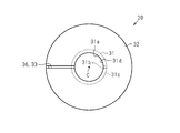
- the rotor 3 is rotatably configured around the center of rotation.
- the rotor 3 rotates about the rotation axis C.
- the rotor 3 is configured so that the stator 2 can be arranged in the space inside the rotor 3.
- the rotor 3 includes a rotor unit 4 corresponding to each phase.
- the plurality of rotor units 4 are laminated in the rotation axis direction DC.
- the rotor unit 4 includes a cylindrical rotating iron core 5 having an inner peripheral surface 5a centered on the rotating shaft center C, and a magnet 6 arranged on the inner peripheral surface 5a of the rotating iron core 5 at predetermined intervals in the circumferential direction. To prepare for.
- the magnet 6 is composed of a permanent magnet.
- the stator 2 includes a plurality of coil units 7.
- the stator 2 includes a coil unit 7 corresponding to each phase.
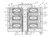
- the plurality of coil units 7 are laminated in the axial direction (direction along the rotation axis direction DC) in the rotation axis direction DC via the non-magnetic material.
- the non-magnetic material is composed of the spacer 8.
- the plurality of coil units 7 are held by the holding member 10.
- the plurality of coil units 7 are connected by the holding member 10.
- the plurality of coil units 7 and the plurality of spacers 8 are alternately laminated in the direction DC in the rotation axis direction and are coupled by the holding member 10.
- the rod portion 13 is inserted into the core insertion holes 42 of the plurality of coil units 7 and the spacer insertion holes 71 of the plurality of spacers 8.
- the first member 11 is attached to one end of the rod portion 13
- the second member 12 is attached to the other end of the rod portion 13, and at least one of the first member 11 and the second member 12 is tightened. Be done. In this way, the plurality of coil units 7 and the plurality of spacers 8 are sandwiched.
- non-magnetic material examples include resin, aluminum, air, and the like.
- a spacer 8 containing the non-magnetic material is arranged between the coil units 7.
- the spacer 8 is arranged between the coil units 7 in order to suppress the influence of magnetism between the phases.
- a first insulating member may be provided between the stator 2 and the first member 11 of the holding member 10. Further, a second insulating member may be provided between the stator 2 and the second member 12 of the holding member 10.
- the holding member 10 is made of a non-magnetic material, the first insulating member and the second insulating member may be omitted.
- the motor 1 is provided with the first insulating member and the second insulating member.
- the coil unit 7 will be described with reference to FIGS. 3 to 9.
- the coil unit 7 has a coil 20 having a winding portion 22 wound around the rotation axis C in an annular shape, and a stator core 40.
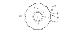
- the coil unit 7 has a bobbin 30.
- the bobbin 30 has a cylindrical portion 31 centered on the rotation axis C and a pair of flanges 32.
- the cylindrical portion 31 has an insertion hole 31a along the rotation axis C.
- the insertion hole 31a is configured to accommodate the first cylindrical portion 52 and the second cylindrical portion 62 of the stator core 40, which will be described later.
- the pair of flanges 32 are provided at both ends of the cylindrical portion 31 in the rotation axis direction DC.
- one of the pair of flanges 32 of the bobbin 30 is provided with a retaining portion 33 to which the lead wire 21 of the coil 20 is fastened.
- the retaining portion 33 is configured as a notch on the outer peripheral edge of the flange 32.
- a through hole 31b that penetrates the flange 32 or the cylindrical portion 31 is provided in the vicinity of the cylindrical portion 31 of the bobbin 30.
- the through hole 31b penetrates from the outer peripheral surface 31c of the cylindrical portion 31 to the inner peripheral surface 31d.
- the through hole 31b is configured to allow the lead wire 21 of the coil 20 to pass through.
- the coil 20 is composed of a conducting wire 21.
- the conducting wire 21 has a core portion for conducting electricity and a coating layer covering the core portion.
- the core is made of metal.
- the core is copper wire.
- the coating layer is composed of an insulator.
- the coating layer is an insulating resin.
- the coil 20 includes a winding portion 22 and two leader wires extending from the winding portion 22 (hereinafter, referred to as “first leader wire 23” and “second leader wire 24”).
- the winding portion 22 is composed of a conducting wire 21 wound around the cylindrical portion 31 of the bobbin 30.
- the winding method of the conductor 21 is not limited.
- the lead wire 21 may be wound around the bobbin 30 in a state where both the first leader wire 23 and the second leader wire 24 are arranged outside the bobbin 30 in the radial DR.
- the first leader line 23 is arranged outside the bobbin 30 in the radial DR
- the second leader line 24 is arranged inside the bobbin 30 in the radial DR.
- the first leader wire 23 can be arranged outside the bobbin 30 by winding the lead wire 21 around the cylindrical portion 31 of the bobbin 30 in a state where the second leader wire 24 is arranged inside the bobbin 30.
- the coil 20 can be formed by any method.
- the first leader wire 23 is a portion including one end of the conductor 21, and the second leader wire 24 is a portion including the other end of the conductor 21.
- the first leader line 23 and the second leader line 24 are drawn from the coil 20 to the outside of the stator 2.
- the stator core 40 is composed of a ferromagnet. Ferromagnets include iron, nickel, cobalt, and compounds containing at least one of these.
- the stator core 40 is configured to hold the bobbin 30.
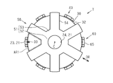
- the stator core 40 includes a central portion 41, first claw magnetic poles 55 arranged at equal intervals on the outer periphery of the bobbin 30, and second claw magnetic poles 65 arranged at equal intervals on the outer periphery of the bobbin 30.
- the central portion 41 is configured to pass through the insertion hole 31a of the cylindrical portion 31 of the bobbin 30.
- the central portion 41 has a core insertion hole 42 extending along the rotation axis C.
- the first claw pole 55 is connected to one end of the rotation axis direction DC at the central portion 41
- the second claw magnetic pole 65 is connected to the other end of the rotation axis direction DC at the central portion 41.
- the central portion 41 is composed of a first cylindrical portion 52 of the first core 50, which will be described later, and a second cylindrical portion 62 of the second core 60.
- the stator core 40 is composed of a plurality of members. An example of the stator core 40 will be described below.
- the stator core 40 is provided so as to surround at least a part of the circumference of the winding portion 22 of the coil 20.
- the stator core 40 has a plurality of protrusions 54, 64.
- a plurality of protrusions 54 and 64 are formed at both ends of the stator core 40 in the axial direction (direction along the rotation axis direction DC) so as to be alternately arranged in the circumferential direction when viewed from the axial direction.
- the projecting portions 54 and 64 project in the radial DR from each of both ends of the stator core 40 in the axial direction (direction along the rotation axis direction DC) toward the rotor 3.
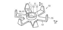
- the stator core 40 has a first core 50 on one side in the axial direction and a second core 60 on the other side in the axial direction.
- the stator core 40 includes a first core 50 and a second core 60 coupled to the first core 50.
- the first core 50 and the second core 60 are composed of a dust core.
- the first core 50 and the second core 60 may be composed of laminated magnetic cores.
- the first core 50 has an annular first ring portion 51, a plurality of first protrusions 54, and a first claw magnetic pole 55 extending in the axial direction.
- the first ring portion 51 includes a first cylindrical portion 52 centered on the rotation axis C, and a first flange portion 53 provided on the outer periphery of the first cylindrical portion 52.
- the first cylindrical portion 52 is configured to fit into the insertion hole 31a of the cylindrical portion 31 of the bobbin 30.
- the first cylindrical portion 52 has a first coupling surface 52a at a position closer to the second core 60 in the rotation axis direction DC.
- a plurality of first protruding portions 54 are provided on the first flange portion 53 at equal intervals in the circumferential direction.
- six first protruding portions 54 are provided on the first flange portion 53.
- the first protruding portion 54 protrudes from the first flange portion 53 in the radial DR.
- the surface of the first flange portion 53 and the first protruding portion 54 near the bobbin 30 is configured to be flat.
- the first claw magnetic pole 55 extends from the tip end portion of the first protruding portion 54 in the direction of the center of rotation DC (axial direction).
- the first claw magnetic poles 55 are arranged at equal intervals along the circumference centered on the rotation axis C of the motor 1.
- the first claw magnetic pole 55 is arranged so as to face the inner peripheral surface of the rotor 3 in a state where the rotor 3 is assembled to the stator 2 (see FIG. 1).
- the second core 60 has an annular second ring portion 61, a plurality of second protrusions 64, and a second claw magnetic pole 65 extending in the axial direction.
- the second ring portion 61 includes a second cylindrical portion 62 centered on the rotation axis C, and a second flange portion 63 provided on the outer periphery of the second cylindrical portion 62.
- the second cylindrical portion 62 is configured to fit into the insertion hole 31a of the cylindrical portion 31 of the bobbin 30.
- the second cylindrical portion 62 has a second coupling surface 62a at a position closer to the first core 50 in the rotation axis direction DC.
- the second coupling surface 62a contacts the first coupling surface 52a (see FIG. 9).
- a plurality of second protruding portions 64 are provided on the second flange portion 63 at equal intervals in the circumferential direction.
- six second protrusions 64 are provided on the second flange portion 63.
- the second protruding portion 64 projects from the second flange portion 63 in the radial DR.
- the surface of the second flange portion 63 and the second protruding portion 64 near the bobbin 30 is configured to be flat.
- the second claw magnetic pole 65 extends from the tip end portion of the second protruding portion 64 in the direction of the center of rotation DC (axial direction).
- the second claw pole 65 is arranged between the first claw poles 55 (see FIG. 7).
- the second claw magnetic pole 65 is arranged at an intermediate position between the two first claw magnetic poles 55 in the circumferential direction centered on the rotation axis C.
- the second claw pole 65 is arranged so as to face the inner peripheral surface of the rotor 3 in a state where the rotor 3 is assembled to the stator 2 (see FIG. 1).
- the first claw pole 55 and the second claw pole 65 are arranged so as to be alternately arranged in the circumferential direction.
- the second core 60 is coupled to the first core 50 so that the second coupling surface 62a is in contact with the first coupling surface 52a of the first core 50.
- the second cylindrical portion 62 of the second core 60 is connected to the first cylindrical portion 52 of the first core 50 by crimping, welding, welding, or bonding.
- the portion where the first cylindrical portion 52 of the first core 50 and the second cylindrical portion 62 of the second core 60 are connected is referred to as a connecting portion 43.
- the core insertion hole 42 of the central portion 41 is configured by connecting the first insertion hole 52b of the first cylindrical portion 52 and the second insertion hole 62b of the second cylindrical portion 62.
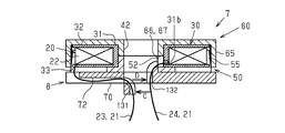
- the coupling portion 43 between the first core 50 and the second core 60 is provided with a gap 66 between the cores between the first core 50 and the second core 60.
- the inter-core gap 66 is configured such that at least one of the first leader line 23 and the second leader line 24 is inserted.
- a notch 67 through which the second leader line 24 is inserted is provided in the first cylindrical portion 52 of the first core 50.
- the bobbin 30 is housed in the annular space formed between the first core 50 and the second core 60. As described above, the first cylindrical portion 52 of the first core 50 and the second cylindrical portion 62 of the second core 60 are inserted into the insertion hole 31a of the bobbin 30. The bobbin 30 is sandwiched by the first flange portion 53 of the first core 50 and the second flange portion 63 of the second core 60. The retaining portion 33 of the flange 32 of the bobbin 30 is arranged in the first range AR1 or the second range AR2 (see FIG. 7).
- the first range AR1 is a range surrounded by two adjacent first protrusions 54 and a first ring 51 in the stator core 40. More specifically, the first range AR1 is located between the first ring portion 51, the two first protrusions 54 adjacent to each other, and the two first protrusions 54 adjacent to each other when viewed from the rotation axis direction DC. It is a range surrounded by the second claw magnetic pole 65 arranged in.
- the second range AR2 is a range surrounded by two second protruding portions 64 and a second ring portion 61 adjacent to each other. More specifically, the second range AR2 is between the second ring portion 61, the two adjacent second protruding portions 64, and the two adjacent second protruding portions 64 when viewed from the rotation axis direction DC. It is a range surrounded by the first claw magnetic pole 55 arranged in.
- the retaining portion 33 of the flange 32 of the bobbin 30 is arranged in the range between the second claw magnetic pole 65 and the winding portion 22 of the coil 20 in the first range AR1.
- the retaining portion 33 of the flange 32 of the bobbin 30 is arranged in the range between the first claw magnetic pole 55 and the winding portion 22 of the coil 20 in the second range AR2.
- At least one of the first leader line 23 and the second leader line 24 is taken out from the first range AR1 or the second range AR2. Then, at least one of the first leader line 23 and the second leader line 24 is arranged so as to pass between the stator cores 40 of the two coil units 7.
- At least one of the first leader line 23 and the second leader line 24 is pulled out from between the second claw pole 65 and the coil 20 in the range of the first range AR1. Alternatively, it may be ejected from between the first claw magnetic pole 55 and the coil 20 in the range of the second range AR2. Then, at least one of the first leader line 23 and the second leader line 24 is arranged so as to pass between the stator cores 40 of the two coil units 7.
- the first leader line 23 is drawn from the outside of the bobbin 30 in the radial DR.
- the retaining portion 33 of the flange 32 of the bobbin 30 is arranged in the range between the second claw magnetic pole 65 and the winding portion 22 of the coil 20 in the first range AR1.
- the first leader wire 23 is hooked on the retaining portion 33 of the flange 32 of the bobbin 30 and is ejected from between the second claw magnetic pole 65 and the coil 20 in the first range AR1 of the first core 50.
- the spacer 8 is arranged between the coil units 7 as described above.
- the spacer 8 contains a non-magnetic material.
- the spacer 8 is preferably formed of a non-magnetic material.
- the spacer 8 is made of resin.
- the spacer 8 may contain air.
- the spacer 8 is formed in a plate shape.
- the spacer 8 includes a spacer main body 70.
- the spacer main body 70 is provided with a spacer insertion hole 71 through which the rod portion 13 of the holding member 10 is inserted.
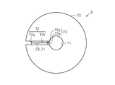
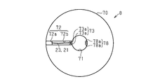
- the spacer 8 has a leader guide 72 that guides at least one of the first leader 23 and the second leader 24.
- the leader guide 72 has an axial guide portion 72a and a radial guide portion 72b.
- the axial guide portion 72a is configured to extend in the rotation axis direction DC on the outer peripheral surface of the spacer main body portion 70.
- the radial guide portion 72b is connected to the axial guide portion 72a, is provided on one surface of the spacer main body 70, and is configured to extend from the outer peripheral edge to the inner peripheral edge of the spacer main body 70.
- the spacer 8 is at least the first engaging portion 73 (see FIG. 8) with which the first leader line 23 is engaged and the second engaging portion 78 (see FIG. 24) with which the second leader wire 24 is engaged.
- the spacer 8 has a first engaging portion 73 with which the first leader line 23 engages.
- the first engaging portion 73 is provided on the leader wire guide 72.
- the first engaging portion 73 is configured as a pair of protrusions 73a that sandwich the first leader wire 23.
- the pair of protrusions 73a project from the side surface of the groove configured as the leader guide 72.
- the arrangement of the first leader line 23 and the second leader line 24 will be described with reference to FIG.
- the first claw magnetic pole 55 and the second claw magnetic pole 65 are arranged on one of the inner peripheral portion and the outer peripheral portion of the stator core 40, and the first leader wire 23 and the second leader wire 24 are arranged on the other side.
- the first claw magnetic pole 55 and the second claw magnetic pole 65 are arranged on the outer peripheral portion of the stator core 40.
- the first leader line 23 and the second leader line 24 are arranged in the inner peripheral portion of the stator core 40.
- the inner peripheral portion PA of the stator core 40 indicates an inner space of a cylinder composed of a surface including the inner peripheral surface of the core insertion hole 42 of the stator core 40.
- the outer peripheral portion of the stator core 40 indicates an outer space of a cylinder composed of a surface including an outer peripheral surface of the stator core 40.
- first leader wire 23 and the second leader wire 24 is arranged so as to pass between the stator cores 40 of the two coil units 7. Further, at least one of the first leader line 23 and the second leader line 24 is arranged so as to pass through the leader line guide 72 of the spacer 8. Further, at least one of the first leader line 23 and the second leader line 24 is arranged so as to pass through the inter-core gap 66 provided between the first core 50 and the second core 60. The first leader line 23 and the second leader line 24 are arranged along the rod guide 14.
- the first leader line 23 is drawn from the outside of the bobbin 30 in the radial DR, is arranged on the leader line guide 72 of the spacer 8 so as to pass between the stator cores 40, and is placed on the inner peripheral portion PA in the stator core 40. It is arranged and is arranged along the bar guide 14.
- the second leader line 24 is arranged inside the bobbin 30 in the radial DR, is inserted through the through hole 31b of the bobbin 30 and the gap 66 between the cores of the stator core 40, and is arranged in the inner peripheral portion PA in the stator core 40. It is arranged along the bar guide 14.
- the holding member 10 includes a first member 11, a second member 12, and a rod portion 13.
- the first member 11 directly or indirectly contacts the first end surface 2a, which is one end surface of the stator 2, in the rotation axis direction DC.
- the second member 12 is configured to come into direct or indirect contact with the second end surface 2b, which is the end surface opposite to the first end surface 2a of the stator 2 in the direction DC in the direction of the rotation axis.
- the rod portion 13 is a member that connects the first member 11 and the second member 12.
- the first member 11 is coupled to the first end portion 13a of the rod portion 13.
- the second member 12 is coupled to the second end portion 13b on the opposite side of the rod portion 13 from the first end portion 13a. At least one of the first member 11 and the second member 12 is connected to the rod portion 13.
- the second member 12 is connected to the rod portion 13 by a screw structure.
- the first member 11 is integrally formed with the rod portion 13.
- the rod portion 13 is configured to penetrate a plurality of coil units 7. Specifically, the rod portion 13 is configured to insert the core insertion hole 42 of each stator core 40.
- a rod guide 14 is provided on the outer periphery of the rod 13. The rod guide 14 extends from the vicinity of the first end 13a to the second end 13b along the longitudinal direction of the rod 13.
- the bar guide 14 is configured to be recessed from the outer peripheral surface of the bar 13 so that at least one of the first leader line 23 and the second leader line 24 can be inserted.
- six rod guides 14 are provided on the outer peripheral surface of the rod 13. Each of the bar guides 14 accommodates one of the first leaders 23 and the second leader 24 of each phase.
- the first member 11 and the rod portion 13 are integrally configured.
- the coil unit 7 is preassembled.
- the first leader wire 23 and the second leader wire 24 are drawn out from the coil 20 of the coil unit 7.
- the coil unit 7 is fitted in the rod portion 13 so that the rod portion 13 passes through the core insertion hole 42, and the first leader wire 23 and the second leader wire 24 are arranged along the separate rod portion guides 14. Will be done.
- the motor 1 is assembled by the following procedure. After the coil unit 7 of the first phase (for example, U phase) is fitted to the rod portion 13, the spacer 8 is fitted to the rod portion 13, and subsequently, the coil unit 7 of the second phase (for example, V phase) is fitted. It is fitted to the rod portion 13.
- the spacer 8 is fitted to the rod portion 13, and subsequently, the coil unit 7 of the third phase (for example, W phase) is fitted to the rod portion 13. Then, the second member 12 is screwed into the second end portion 13b of the rod portion 13. By tightening the second member 12, the three coil units 7 and the two spacers 8 are held by the holding member 10.
- the coil unit 7 of the third phase for example, W phase
- the first claw magnetic pole 55 and the second claw magnetic pole 65 are arranged on one of the inner peripheral portion PA and the outer peripheral portion of the stator core 40. If at least one of the first leader wire 23 and the second leader wire 24 is arranged in the same portion of the stator core 40 as the portion where the first claw magnetic pole 55 and the second claw magnetic pole 65 are arranged, the stator 2 and the stator 2 At least one of the first leader line 23 and the second leader line 24 will be arranged in the air gap with the rotor 3. In this case, at least one of the first leader line 23 and the second leader line 24 may come into contact with the rotor 3.
- first leader line 23 and the second leader line 24 are wired so as not to pass through the air gap between the rotor 3 and the stator 2 or the vicinity of the air gap.
- first leader line 23 and the second leader line 24 are wired so that the air gap between the rotor 3 and the stator 2 or the portion passing near the air gap is shortened. As a result, it is possible to prevent the first leader line 23 and the second leader line 24 from coming into contact with the rotor 3.
- At least one of the first leader wire 23 and the second leader wire 24 of the coil 20 is arranged so as to pass between the stator cores 40 of the two coil units 7.
- the first claw magnetic pole 55 and the second claw magnetic pole 65 are arranged on one of the inner peripheral portion PA and the outer peripheral portion of the stator core 40, and the first leader wire 23 and the second leader wire 24 are arranged on the other side. ..
- the first leader wire 23 and the second leader wire 24 are not arranged in the air gap between the rotor 3 and the stator 2, the first leader wire 23 and the second leader wire 24 are connected to the rotor 3. Contact can be suppressed.
- a spacer 8 containing a non-magnetic material is arranged between the coil units 7. At least one of the first leader line 23 and the second leader line 24 is arranged so as to pass through the leader line guide 72 of the spacer 8. According to this configuration, the positional deviation of the leader wire between the coil units 7 can be suppressed.
- the spacer 8 has at least one of a first engaging portion 73 with which the first leader wire 23 is engaged and a second engaging portion 78 with which the second leader wire 24 is engaged. According to this configuration, it is possible to suppress the movement of at least one of the first leader line 23 and the second leader line 24 due to the vibration of the motor 1. Alternatively, at least one of the first leader wire 23 and the second leader wire 24 can suppress wear caused by the vibration of the leader wire caused by the vibration of the motor 1.
- At least one of the first leader line 23 and the second leader line 24 is taken out from the first range AR1 or the second range AR2 and is arranged so as to pass between the stator cores 40 of the two coil units 7. According to this configuration, at least one of the first leader line 23 and the second leader line 24 can be easily wired.
- At least one of the first leader line 23 and the second leader line 24 is pulled out from between the second claw pole 65 and the coil 20 in the range of the first range AR1. Alternatively, it is ejected from between the first claw magnetic pole 55 and the coil 20 in the range of the second range AR2. Then, it is arranged so as to pass between the stator cores 40 of the two coil units 7. According to this configuration, at least one of the first leader wire 23 and the second leader wire 24 is sandwiched between the first claw pole 55 and the coil 20, or between the second claw pole 65 and the coil 20. NS. Thereby, at least one of the first leader line 23 and the second leader line 24 can be prevented from deviating from the air gap between the rotor 3 and the stator 2.
- At least one of the first leader line 23 and the second leader line 24 is provided between the first core 50 and the second core 60 in the coupling portion 43 between the first core 50 and the second core 60. It is arranged so as to pass through the gap 66 between the cores.
- the first leader line 23 and the second leader line 24 are arranged along the rod guide 14 of the holding member 10. According to this configuration, the movement of the first leader line 23 and the second leader line 24 due to the vibration of the motor 1 can be suppressed.
- the motor 1 further includes a bobbin 30.
- the winding portion 22 of the coil 20 is composed of a conducting wire 21 wound around the cylindrical portion 31 of the bobbin 30.
- the stator core 40 holds the bobbin 30. According to this configuration, the coil 20 can be positioned with respect to the stator core 40 by simple assembly.
- the position where the first leader line 23 is drawn out is different in the bobbin 30 as compared with the embodiment.
- the retaining portion 33 of the bobbin 30 is configured as a notch near the outer edge of the flange 32.
- the retaining portion 33 of the bobbin 30 is configured as a slit 34 extending in the radial DR. The width of the slit 34 is configured to be large enough for the first leader line 23 to pass through.
- the first leader line 23 is drawn from the vicinity of the cylindrical portion 31 of the bobbin 30.
- the spacer 8 is also provided with a slit (see the spacer slit 75 in FIG. 21).
- the first leader line 23 passes through the slit 34 of the bobbin 30, the first range AR1 of the first core 50, and the slit of the spacer 8, and is guided to the bar guide 14 of the bar 13 of the holding member 10.
- a portion of the first leader wire 23 that passes through the slit of the spacer 8 is arranged between the stator cores 40.
- the slit 34 of the bobbin 30 may be applied instead of the through hole 31b through which the second leader line 24 passes.
- the retaining portion 33 of the bobbin 30 is configured as a notch near the outer edge of the flange 32.
- the retaining portion 33 of the bobbin 30 is configured as a through hole 35 near the cylindrical portion 31 in the flange 32.
- the spacer 8 is also provided with a slit (see the spacer slit 75 in FIG. 21).
- the first leader line 23 passes through the through hole 35 of the bobbin 30, the first range AR1 of the first core 50, and the slit of the spacer 8, and is guided to the bar guide 14 of the bar 13 of the holding member 10.
- the through hole 35 of this modification may be applied instead of the through hole 31b through which the second leader line 24 passes.
- the coil unit 7 shown in FIGS. 16 and 17 includes a bobbin 30 of a second modification.
- the core retaining portion 56 is provided on the first flange portion 53.
- the core retaining portion 56 is configured as a recess with which the first leader wire 23 is engaged.
- the core retaining portion 56 is provided in the first range AR1 of the first core 50.
- the first leader line 23 is hooked on the core retaining portion 56. As a result, the movement of the first leader line 23 due to the vibration of the motor 1 can be suppressed.
- the retaining portion 33 of the bobbin 30 may be configured in the groove 36.
- the groove 36 is provided on the flange 32 of the pair of flanges 32 closer to the first core 50, and is provided on the surface opposite to the surface closer to the coil 20.
- the thickness of the flange 32 provided with the groove 36 is larger than the thickness of the flange 32 without the groove 36.
- the width of the groove 36 is configured to be large enough for the first leader line 23 to pass through.
- the spacer 8 has a spacer slit 75 extending in the radial DR.
- the width of the spacer slit 75 is configured to be large enough for the first leader line 23 to pass through.
- the spacer slit 75 is provided with a first engaging portion 73 with which the first leader wire 23 is engaged.
- the first engaging portion 73 is composed of a pair of protrusions 73b.
- the tip portions of the pair of protrusions 73b are partially connected and separated from each other in the rotation axis direction DC.
- the shape of the spacer slit 75 is maintained by a partial connection between the pair of protrusions 73b.
- the first leader line 23 is sandwiched between a pair of protrusions 73b at portions separated from each other.
- the spacer 8 is not fitted to the rod portion 13 of the holding member 10, but is sandwiched and supported between the coil units 7.
- the spacer main body 77 is formed in an annular shape.
- the inner diameter of the spacer main body 77 is larger than the diameter of the rod 13.
- the inner diameter of the spacer body 77 is substantially equal to the diameter of the bobbin 30.
- the spacer 8 forms an air layer 77a (a layer of non-magnetic material) between the coil units 7.
- the first leader line 23 passes through the inside of the spacer main body portion 77.
- the shape of the spacer 8 is not limited to the form shown in the embodiment.
- the shape of the spacer 8 may be rectangular or triangular.
- the spacer 8 has a second engaging portion 78 to which the second leader 24 engages.
- the second engaging portion 78 is provided on the inner peripheral surface of the spacer insertion hole 71 of the spacer 8.
- the second engaging portion 78 is configured as a pair of claw portions 78a for holding the second leader line 24.
- the second leader line 24 is held by the second engaging portion 78. According to this configuration, the movement of the second leader line 24 due to the vibration of the motor 1 can be suppressed.
- the first ring portion 51 of the first core 50 has an annular connecting ring portion (not shown) connecting the six first protruding portions 54 and three third rings provided at equal intervals on the inner peripheral portion of the connecting ring portion.
- 1 Fitting portion 91 is provided.
- the first fitting portion 91 extends in the direction DC in the direction of the axis of rotation.
- the second ring portion 61 of the second core 60 has the same structure as the first ring portion 51 of the first core 50, and includes a connecting ring portion 92 and a second fitting portion 93.
- the first core 50 and the second core 60 are coupled by fitting the second fitting portion 93 of the second core 60 between the first fitting portions 91 of the first core 50. According to this structure, the first core 50 and the second core 60 can be connected by a fitting structure.
- the core gap 66 is provided between the first fitting portion 91 and the second fitting portion 93.
- the inter-core gap 66 is configured as a notch 94 of the first fitting portion 91.
- the notch portion 94 may be provided in the second fitting portion 93.
- the cutout portion 94 is configured so that the second leader line 24 passes through the notch portion 94. According to such a structure, in the manufacture of the motor 1, the second leader line 24 can be arranged when the first core 50 and the second core 60 are connected, so that the production efficiency of the motor 1 can be improved.
- ⁇ 9th modification> It is preferable that the portion of at least one of the first leader wire 23 and the second leader wire 24 that contacts the stator core 40 is surrounded by the insulating member 98. Examples are given in the 9th modification and the 10th modification.
- FIG. 29 is a view seen from the direction of arrow A in FIG. 28.
- the cylindrical portion 31 of the bobbin 30 is provided with a protruding portion 95.
- the protruding portion 95 projects in the radial DR from the inner peripheral surface of the cylindrical portion 31.
- the protrusion 95 is provided with a through hole 96 through which the second leader line 24 is inserted.
- the protrusion 95 is made of an insulating resin.
- the first core 50 is provided with a notch 97 into which the protrusion 95 is inserted.
- the portion of the second leader wire 24 that comes into contact with the stator core 40 is surrounded by the insulating member 98. According to this configuration, the creepage distance between the second leader wire 24 and the stator core 40 can be secured, and the insulation performance can be improved.
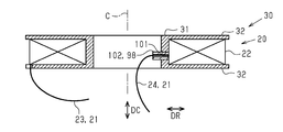
- FIG. 32 is a view seen from the direction of arrow B in FIG.
- the cylindrical portion 31 of the bobbin 30 is provided with a tube through hole 101 through which the tube 102 passes.
- the tube 102 is made of an insulating resin.
- the tube through hole 101 extends in the radial DR in the cylindrical portion 31.
- a tube 102 is arranged in the tube through hole 101.
- the second leader line 24 inserts the tube 102.
- the first core 50 is provided with a tube notch 103 into which the tube 102 is inserted.
- the portion of the second leader wire 24 that comes into contact with the stator core 40 is surrounded by the insulating member 98. According to this configuration, the creepage distance between the second leader wire 24 and the stator core 40 can be secured, and the insulation performance can be improved.
- the tube 104 may be configured such that the cross-sectional area expands from the first end to the second end.
- the cross-sectional area indicates the area of the cross section that intersects the line along the through hole of the tube 104.
- the first end is arranged on the inner peripheral surface side of the cylindrical portion 31 of the bobbin 30, and the second end is arranged on the outer peripheral surface side of the cylindrical portion 31 of the bobbin 30.
- the tube 104 is preferably elastic. According to such a tube 104, the contact between the second leader wire 24 and the first core 50 can be suppressed as compared with the cylindrical tube 104. It is also possible to secure the creepage distance.
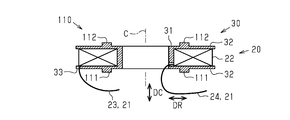
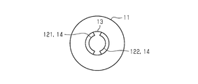
- the bobbin 30 has a positioning portion 110.
- the positioning portion 110 includes a first convex portion 111 and a second convex portion 112 that engage with the stator core 40.
- the first convex portion 111 and the second convex portion 112 are provided on the outer surface of the flange 32.
- the first convex portion 111 is configured to be in contact with the two first protruding portions 54 and the first flange portion 53 of the first core 50.
- the two first convex portions 111 are provided at positions symmetrical with respect to the rotation axis C.
- the second convex portion 112 is configured to be in contact with the two second protruding portions 64 and the second flange portion 63 of the second core 60.
- the two second convex portions 112 are provided at positions symmetrical with respect to the rotation axis C. According to this configuration, the bobbin 30 can be easily positioned with respect to the stator core 40.
- the bobbin 30 has a positioning portion 110.
- the positioning portion 110 includes a plurality of convex portions 113 that engage with the stator core 40.
- the plurality of protrusions 113 are provided on at least one of the two flanges 32 of the bobbin 30.
- the convex portion 113 is provided on the outer peripheral edge of the flange 32 so as to project in the radial DR.
- each convex portion 113 in the flange 32 in contact with the first core 50, each convex portion 113 is arranged between the first claw magnetic pole 55 and the second claw magnetic pole 65, and is configured to be in contact with both magnetic poles. According to this configuration, the bobbin 30 can be easily positioned with respect to the stator core 40.
- FIG. 39 is a plan view of a member in which the first member 11 and the rod portion 13 are connected.
- the rod portion 13 of the holding member 10 is provided with a first guide 121 and a second guide 122 as the rod portion guide 14.
- the first guide 121 is configured to accommodate three first leader lines 23.
- the second guide 122 is configured to accommodate three second leaders 24. According to this configuration, the structure of the rod portion 13 can be simplified.
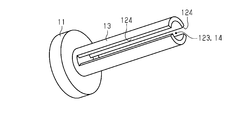
- FIG. 40 is a plan view of a member in which the first member 11 and the rod portion 13 are connected.
- the rod portion 13 of the holding member 10 is provided with a leader line accommodating portion 123 as a rod portion guide 14.
- the leader line accommodating portion 123 is configured to contain three first leader lines 23 and three second leader lines 24.
- the leader line accommodating portion 123 is configured as a space along the rotation axis C in the rod portion 13.
- a slit 124 connected to the leader line accommodating portion 123 is provided on the side surface of the rod portion 13 (see FIG. 41).
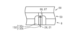
- the spacer 8 has at least one of a first bending guide 131 and a second bending guide 132.
- the first bending guide 131 smoothly bends the first leader wire 23. Specifically, the first bending guide 131 guides the first leader line 23 so that the first leader line 23 does not break.
- the second bending guide 132 smoothly bends the second leader wire 24. Specifically, the second bending guide 132 guides the second leader line 24 so that the second leader line 24 does not break.
- the first bending guide 131 includes a first guide main body portion 131a and a first guide groove 131b provided in the first guide main body portion 131a.
- the first guide main body portion 131a is provided at a portion where the inner peripheral surface of the spacer insertion hole 71 and the leader wire guide 72 intersect, and is a direction along the rotation axis C to guide the first leader wire 23 (the direction along the rotation axis C. Hereafter, it extends in the leader line guidance direction).
- the leader line guiding direction is the direction toward the second member 12 (see FIG. 1).
- the first guide groove 131b is formed in the first guide main body portion 131a so as to be continuous with the leader wire guide 72.
- the first guide groove 131b extends in the leader guide direction as it approaches the rotation axis C, and gently curves.
- the second bending guide 132 includes a second guide main body portion 132a and a second guide groove 132b provided in the second guide main body portion 132a.
- the second guide main body 132a is provided on the inner peripheral surface of the spacer insertion hole 71 at a portion where the second leader line 24 is output.
- the second guide main body 132a extends along the inner peripheral surface of the first cylindrical portion 52 of the first core 50 from which the second leader line 24 is output to the vicinity of the notch 67 (gap between cores 66) of the first core 50. ..
- the second guide groove 132b is formed in the second guide main body portion 132a so as to be connected to the notch portion 67 of the first core 50.
- the second guide groove 132b extends in the leader guide direction as it approaches the rotation axis C, and gently curves. According to this configuration, at least one of the first leader line 23 and the second leader line 24 is smoothly bent, so that at least one break of the first leader line 23 and the second leader line 24 can be suppressed.
- the motor 1 of the present disclosure may be a combination of, for example, the following modifications and at least two modifications that do not contradict each other.
- the motor 1 is an outer rotor type motor and has a claw pole type stator, but the technique of the present disclosure can also be applied to the stator of the inner rotor type motor.
- the inner rotor type motor is used.
- the first leader line 23 and the second leader line 24 are arranged on the outer peripheral portion of the stator.
Landscapes
- Engineering & Computer Science (AREA)
- Power Engineering (AREA)
- Insulation, Fastening Of Motor, Generator Windings (AREA)
- Iron Core Of Rotating Electric Machines (AREA)
Priority Applications (3)
| Application Number | Priority Date | Filing Date | Title |
|---|---|---|---|
| EP21804029.3A EP4152571A4 (en) | 2020-05-11 | 2021-04-26 | ENGINE |
| CN202180033752.6A CN115516739B (zh) | 2020-05-11 | 2021-04-26 | 马达 |
| US17/923,905 US12244175B2 (en) | 2020-05-11 | 2021-04-26 | Motor |
Applications Claiming Priority (2)
| Application Number | Priority Date | Filing Date | Title |
|---|---|---|---|
| JP2020083256A JP7223233B2 (ja) | 2020-05-11 | 2020-05-11 | モータ |
| JP2020-083256 | 2020-05-11 |
Publications (1)
| Publication Number | Publication Date |
|---|---|
| WO2021230058A1 true WO2021230058A1 (ja) | 2021-11-18 |
Family
ID=78510633
Family Applications (1)
| Application Number | Title | Priority Date | Filing Date |
|---|---|---|---|
| PCT/JP2021/016594 Ceased WO2021230058A1 (ja) | 2020-05-11 | 2021-04-26 | モータ |
Country Status (6)
| Country | Link |
|---|---|
| US (1) | US12244175B2 (https=) |
| EP (1) | EP4152571A4 (https=) |
| JP (2) | JP7223233B2 (https=) |
| CN (1) | CN115516739B (https=) |
| TW (1) | TWI793591B (https=) |
| WO (1) | WO2021230058A1 (https=) |
Families Citing this family (3)
| Publication number | Priority date | Publication date | Assignee | Title |
|---|---|---|---|---|
| JP7256431B1 (ja) * | 2021-09-30 | 2023-04-12 | ダイキン工業株式会社 | 回転電機、送風機、圧縮機、冷凍装置 |
| JP7364951B1 (ja) * | 2022-03-30 | 2023-10-19 | ダイキン工業株式会社 | 回転電機、送風機、圧縮機、冷凍装置、車両 |
| CN120728933A (zh) * | 2024-03-29 | 2025-09-30 | 比亚迪股份有限公司 | 定子组件、直线电机、电磁悬架及车辆 |
Citations (4)
| Publication number | Priority date | Publication date | Assignee | Title |
|---|---|---|---|---|
| JP2007049844A (ja) * | 2005-08-11 | 2007-02-22 | Shinano Kenshi Co Ltd | アウターロータ型モータ |
| JP2013013209A (ja) * | 2011-06-29 | 2013-01-17 | Shinano Kenshi Co Ltd | アウターロータ型モータの固定子構造 |
| JP2013150373A (ja) * | 2012-01-17 | 2013-08-01 | Shinano Kenshi Co Ltd | 永久磁石型ステッピングモータ一体型回転機構 |
| JP2013158072A (ja) | 2012-01-26 | 2013-08-15 | Shinano Kenshi Co Ltd | アウターロータ型モータ |
Family Cites Families (13)
| Publication number | Priority date | Publication date | Assignee | Title |
|---|---|---|---|---|
| US20060238059A1 (en) * | 2003-08-19 | 2006-10-26 | Fumito Komatsu | Synchronous motor |
| JP4649131B2 (ja) * | 2004-06-22 | 2011-03-09 | 日本電産シバウラ株式会社 | モールドモータ |
| WO2008136061A1 (ja) * | 2007-04-19 | 2008-11-13 | Mitsubishi Electric Corporation | 電動機及びポンプ及び電動機の製造方法 |
| JP2008278659A (ja) * | 2007-04-27 | 2008-11-13 | Mitsumi Electric Co Ltd | アウタロータ型モータ |
| JP5547021B2 (ja) * | 2010-10-01 | 2014-07-09 | シナノケンシ株式会社 | アウターロータ型モータの固定子構造 |
| EP2466723A1 (de) * | 2010-12-20 | 2012-06-20 | Cyoris Ag | Transversalflussmaschine |
| CN103378711B (zh) * | 2012-04-17 | 2015-05-06 | 余虹锦 | 双机械端口磁导谐波式电磁齿轮复合永磁电机 |
| JP6286170B2 (ja) * | 2013-09-27 | 2018-02-28 | 株式会社ミツバ | ハブダイナモ |
| JP6585372B2 (ja) * | 2015-04-28 | 2019-10-02 | 日本電産株式会社 | モータ |
| JP2017046420A (ja) * | 2015-08-25 | 2017-03-02 | アスモ株式会社 | ロータ、ステータ及びモータ |
| US20180269729A1 (en) * | 2015-12-03 | 2018-09-20 | Asmo Co., Ltd. | Motor and method for manufacturing stator |
| JP2019134525A (ja) * | 2018-01-29 | 2019-08-08 | 日本電産株式会社 | ステータ、モータ、及び送風機 |
| JP7385144B2 (ja) * | 2019-03-28 | 2023-11-22 | ダイキン工業株式会社 | モータ |
-
2020
- 2020-05-11 JP JP2020083256A patent/JP7223233B2/ja active Active
-
2021
- 2021-04-26 WO PCT/JP2021/016594 patent/WO2021230058A1/ja not_active Ceased
- 2021-04-26 US US17/923,905 patent/US12244175B2/en active Active
- 2021-04-26 CN CN202180033752.6A patent/CN115516739B/zh active Active
- 2021-04-26 EP EP21804029.3A patent/EP4152571A4/en active Pending
- 2021-05-07 TW TW110116517A patent/TWI793591B/zh active
-
2023
- 2023-02-03 JP JP2023015652A patent/JP2023041924A/ja active Pending
Patent Citations (4)
| Publication number | Priority date | Publication date | Assignee | Title |
|---|---|---|---|---|
| JP2007049844A (ja) * | 2005-08-11 | 2007-02-22 | Shinano Kenshi Co Ltd | アウターロータ型モータ |
| JP2013013209A (ja) * | 2011-06-29 | 2013-01-17 | Shinano Kenshi Co Ltd | アウターロータ型モータの固定子構造 |
| JP2013150373A (ja) * | 2012-01-17 | 2013-08-01 | Shinano Kenshi Co Ltd | 永久磁石型ステッピングモータ一体型回転機構 |
| JP2013158072A (ja) | 2012-01-26 | 2013-08-15 | Shinano Kenshi Co Ltd | アウターロータ型モータ |
Non-Patent Citations (1)
| Title |
|---|
| See also references of EP4152571A4 |
Also Published As
| Publication number | Publication date |
|---|---|
| TW202147741A (zh) | 2021-12-16 |
| EP4152571A1 (en) | 2023-03-22 |
| US12244175B2 (en) | 2025-03-04 |
| JP2021180539A (ja) | 2021-11-18 |
| EP4152571A4 (en) | 2024-05-29 |
| JP2023041924A (ja) | 2023-03-24 |
| JP7223233B2 (ja) | 2023-02-16 |
| TWI793591B (zh) | 2023-02-21 |
| US20230179032A1 (en) | 2023-06-08 |
| CN115516739A (zh) | 2022-12-23 |
| CN115516739B (zh) | 2026-03-10 |
Similar Documents
| Publication | Publication Date | Title |
|---|---|---|
| JP5306411B2 (ja) | 回転電機 | |
| CN103688445B (zh) | 电动机的定子和永磁式旋转电机 | |
| US8154163B2 (en) | Electric power collection/distribution ring of rotary electric machine | |
| US9614407B2 (en) | Rotary electric machine stator | |
| JP2023041924A (ja) | モータ | |
| WO2018038246A1 (ja) | モータ | |
| US10840656B2 (en) | Bus bar unit and rotary electric machine having the same | |
| CN107251373B (zh) | 旋转电机及旋转电机用绝缘件 | |
| US10818427B2 (en) | Stator assembly including a bobbin having an extension tab and a retention rib | |
| JPWO2004030180A1 (ja) | アウタロータ型多極発電機用ステータ及びその組立方法 | |
| JP6062134B1 (ja) | 固定子および電動機 | |
| JP2020025463A (ja) | ブラシレスモータ | |
| US10396613B2 (en) | Armature, rotating electrical device, and armature manufacturing method | |
| JP6771590B2 (ja) | アキシャルギャップ型回転電機 | |
| JP2009017667A (ja) | ステータ | |
| JP6200854B2 (ja) | 回転電機のステータ | |
| JP2012105372A (ja) | 外転型の電動機 | |
| JP2012105371A (ja) | 外転型の電動機 | |
| CN110785914A (zh) | 旋转电机 | |
| CN203722367U (zh) | 旋转电机 | |
| WO2018173462A1 (ja) | ステータ、及びモータ | |
| JP2021035304A (ja) | ステータ、及び、モータ | |
| US20250253720A1 (en) | Stator and motor | |
| JP2023053644A (ja) | ステータ、それを備えるモータ及びステータの製造方法 | |
| JP2015091158A (ja) | 電機子、回転電機及び電機子の製造方法 |
Legal Events
| Date | Code | Title | Description |
|---|---|---|---|
| 121 | Ep: the epo has been informed by wipo that ep was designated in this application |
Ref document number: 21804029 Country of ref document: EP Kind code of ref document: A1 |
|
| NENP | Non-entry into the national phase |
Ref country code: DE |
|
| ENP | Entry into the national phase |
Ref document number: 2021804029 Country of ref document: EP Effective date: 20221212 |
|
| WWG | Wipo information: grant in national office |
Ref document number: 17923905 Country of ref document: US |